1
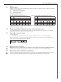
DDLE Basis 11 DDLE Basis 13 DDLE Basis 18 DDLE Basis 18/21/24 DDLE Basis 27 Elektronisch gesteuerter Durchlauferhitzer Bedienungs- und Installationsanleitung ...........................2 Electronically controlled instantaneous water heater Operating and installation instructions ..........................18 Elektronicznie sterowany przepływowy ogrzewacz wody Instrukcja obsługi i instalacji .................................................34 Проточные водонагреватели с электронным управлением Инструкция по эксплуатации и установке ...........48 Електронски управуван проточен бојлер Упатство за ракување и инсталација .......................64 A 14 15 13 16 12 17 10 11 18 7 8 9 6 5 4 3 20 21 22 23 24 25 2 1 26 19 B C26_02_02_0759 28 29 20 4 5 a C26_02_02_0763 19 20 29 C26_02_02_0760 b 3 4 H a E C26_02_02_0766 b b C26_02_02_0753 6 a 26_02_02_0526 4 C26_02_02_0762 a WW WW b 26_02_02_0990 a C26_02_02_0761 C D KW KW F a b G 21 20 14 I 23 5 N a 18 Nm ADEo 70 WD a 26_02_02_1006 O a c d a b b C26_02_02_0767 26_02_02_0764 C26_02_02_0771 LR 1-A C26_02_02_0830 L C26_02_02_0765 J K e c d M c 25 a 24 b 31 30 21 For users and contractors Thank you for purchasing this instantaneous water heater from AEG Haustechnik. You have chosen a high-grade device made in Germany. Even during the development and manufacture, AEG Haustechnik recognises the high value of manufacturing processes that are environmentally responsible and treat resources with care. Thanks to many product innovations, devices made by AEG Haustechnik are amongst the most energy-efficient in their class. 1. Operating instructions 1.1 Equipment description The instantaneous water heater DDLE Basis heats water as it flows through the equipment. You can adjust the DHW outlet temperature anywhere between approx. 30 °C and approx. 60 °C via a temperature selector. From a flow rate of approx. 3 l/min onwards, the control regulates the correct heating output, subject to the temperature selection and the cold water temperature. 1.2 Vital facts in brief s4EMPERATURESELECTOR Turning the selector lets you freely choose the required temperature. Wash basin ( 35 °C ) Shower ( 40 °C) Bath ( 45 °C ) Sink ( 55 °C ) Should the outlet temperature fail to reach the required level, when the tap is fully opened, and the temperature selector has been set to maximum (temperature selector turned fully clockwise), then more water flows through the equipment than can be heated by the internal heater cartridge (output limit 11;13,5; 18; 21; 24 or 27 kW). In such cases, reduce the flow rate at the tap accordingly. s4EMPERATURELIMIT A contractor can set the temperature limit to 43 °C at the device. You can still adjust the temperature selector across its entire range. The outlet temperature will be permanently limited to 43 °C. A temperature range 30 °C to 43 °C can be selected. 1.3 ! 1.4 ! Safety information 4HEREISARISKOFSCALDINGATOUTLETTEMPERATURESINEXCESSOFª# Where children or persons with limited physical, sensory or mental capabilities are to be allowed to control this equipment ensure that this will only happen under supervision or after appropriate instructions by a person responsible for their safety. Children should be supervised to ensure that they do not play with the equipment - risk of scalding. Important information )FTHEWATERSUPPLYTOTHEINSTANTANEOUSWATERHEATERHASBEENINTERRUPTEDEGBECAUSEOFARISKOFFROST ORWORKONTHEWATERSYSTEMTAKETHEFOLLOWINGMEASURESPRIORTOTAKINGTHEEQUIPMENTBACKINTOUSE 1. Remove fuses or trip the appropriate MCBs. 2. Open a tap downstream of the equipment long enough, until all air has been vented from the equipment and its cold water supply pipe. 3. Replace the fuses or reset the relevant MCBs. 22 For users and contractors 1.5 DHW output Subject to season, the following maximum mixed water or draw-off capacities result for different cold water temperatures (see Table 1): ϑ1 = Cold water inlet temperature ϑ2 = Mixed water temperature ϑ3 = Outlet temperature. !VAILABLETEMPERATUREEGFOR Shower, washing hands, filling a bath, etc. Kitchen sink and when using thermostatic valves. ϑ2 = 38 °C 11 13.5 l/min * 5.0 6.0 5.6 6.9 6.6 8.1 ϑ3 = 60 °C 11 13.5 l/min * 3.6 3.1 3.8 3.4 4.2 kW 18 21 24 27 kW 18 21 24 27 ϑ1 ϑ1 6 °C 8.0 9.4 10.7 12.1 6 °C 4.8 5.6 6.4 7.2 10 °C 9.2 10.7 12.3 13.8 10 °C 5.2 6.0 6.9 7.7 14 °C 10.7 12.5 14.5 16.1 14 °C 5.6 6.5 7.5 8.4 Table 1 * Table values relative to a rated voltage of 400 V. The outlet volume is subject to the available supply pressure and the available mains voltage. 1.6 Recommended settings when using a thermostatic valve To safeguard the function of the thermostatic valves, set the instantaneous water heater to its maximum temperature (temperature selector to the right end stop). 1.7 First aid in case of faults s Check all fuses. s Check taps/valves and shower heads for scaling or contamination (see also "6. Troubleshooting"). Where a contractor is required, he can better and more speedily remedy the fault if you provide him with some of the details from the type plate ( A 20): DDLE Basis . . 1.8 ! 1.9 ! No.: . . . . . . - . . . . -. . . . . Maintenance and care -AINTENANCEWORKEGCHECKINGTHEELECTRICALSAFETYMUSTONLYBECARRIEDOUTBYAQUALIlEDCONTRACTOR A damp cloth is sufficient for cleaning the casing. Do not use abrasive or corrosive cleaning agents. Operating and installation instructions +EEPTHESEINSTRUCTIONSSAFELYANDPASSTHEMONTOANYNEWUSERSHOULDTHEEQUIPMENTCHANGEHANDS ,ETYOURCONTRACTORCHECKTHEIRCONTENTINCONJUNCTIONWITHANYMAINTENANCEORREPAIRWORK 23 For contractors 2. Installation instructions Only trained and authorised experts must install the device and make the electrical connection under full observance of these installation instructions. 2.1 Equipment layout 1 2 3 4 5 6 7 8 9 10 11 12 13 14 15 16 2.2 A - O Temperature selector Equipment cap Base, back panel DHW compression fitting Cold water compression fitting Top, back panel Electronics Coding card for output selection for the DDLE Basis 18/21/24 LED diagnostic “traffic light” for operating and fault indications Plug-in position from the temperature selector cable Safety pressure limiter (AP 3) with reset button Mains terminal Knock-out for power connection from above Fixing toggle High limit safety cut-out (STB) with reset button Heating system 17 18 19 20 21 22 23 24 Flow sensor Temperature selector plug “set T” Type plate Mounting bracket Stud for mounting bracket Cable grommet (power cable from above/below) Twin nipple (cold water with shut off valve) Flat packing 25 Screws/rawl plugs for fixing the back panel in case of water connection on finished walls 26 Second flow limiter, only for the DDLE Basis 18/21/24 (secured to the cold water pipe) 27 Installation and operating instructions 28 29 30 31 Installation template Sieve Flow limiter Profile washer Brief description This electronically regulated instantaneous water heater is a pressure device for the heating of cold water to DIN 1988 that can supply one or several draw-off points. The bare wire heating system is suitable for hard and soft water areas (for application range, see “5.2 Application areas”). 2.3 ! 2.4 Important information s !IRINTHECOLDWATERSUPPLYCANDESTROYTHEBAREWIREHEATINGSYSTEMINSIDETHEEQUIPMENTORCANTRIP THESAFETYSYSTEM)FTHEWATERSUPPLYTOTHEINSTANTANEOUSWATERHEATERHASBEENINTERRUPTEDEG BECAUSEOFARISKOFFROSTORWORKONTHEWATERSYSTEMTAKETHEFOLLOWINGMEASURESPRIORTOTAKINGTHE EQUIPMENTBACKINTOUSE 2EMOVEFUSESORTRIPTHEAPPROPRIATE-#"S /PENANDCLOSEATAPDOWNSTREAMOFTHEEQUIPMENTSEVERALTIMESUNTILALLAIRHASBEENVENTED FROMTHECOLDWATERSUPPLYLINEUPSTREAMANDTHEEQUIPMENT 2EPLACETHEFUSESORRESETTHERELEVANT-#"S 4HEINSTANTANEOUSWATERHEATERISEQUIPPEDWITHANAIRDETECTORWHICHTOTHEGREATESTEXTENT PREVENTSDAMAGETOTHEHEATINGSYSTEM )FDURINGOPERATIONAIRISDRAWNINTOTHEINSTANTANEOUSWATERHEATERTHEEQUIPMENTSHUTSDOWN THEHEATINGLOADFORONEMINUTETHEREBYPROTECTINGTHEEQUIPMENT s 4APS n $IRECTDRAWOFFTAPFORINSTANTANEOUSWATERHEATER!$%O7$MONOLEVERMIXERWITH BATHHANDSHOWERCHANGEOVERPARTNO 4HEINSTALLATIONMAYBECARRIEDOUTUSINGCOMMERCIALLYAVAILABLEPRESSURETESTEDTAPS &ORTHERMOSTATICPRESSURETESTEDVALVESSEEINFORMATION2ECOMMENDEDADJUSTMENT s !LWAYSCAREFULLYOBSERVEALLINFORMATIONINTHESEOPERATINGANDINSTALLATIONINSTRUCTIONS 4HESECONTAINIMPORTANTINFORMATIONREGARDINGSAFETYOPERATIONINSTALLATIONANDMAINTENANCEOFTHIS EQUIPMENT Instructions and regulations s 4HEINSTALLATIONWATERANDELECTRICALWORKANDCOMMISSIONINGASWELLASTHEMAINTENANCEOFTHIS equipment, must only be carried out by a qualified contractor in accordance with these instructions. s 0ERFECTFUNCTIONANDSAFEOPERATIONCANONLYBEASSUREDWHENUSINGORIGINALACCESSORIESANDSPAREPARTS intended for this equipment. s /BSERVEALLLOCALLYAPPLICABLEINSTRUCTIONSANDREGULATIONSREGARDINGWATERANDELECTRICALCONNECTIONSSUCH as DIN VDE 0100, DIN 1988, EN 806, DIN 4109, DIN 44851. 24 For contractors ! s /BSERVEALLREGULATIONSOFYOURLOCALWATERANDELECTRICITYSUPPLYCOMPANIES s /BSERVETHETYPEPLATE ( A 19). s 3EE3PECIlCATION 4HESPECIlCELECTRICALRESISTANTOFTHEWATERUSEDMUSTNOTFALLBELOWTHATSTATEDONTHETYPEPLATE)NA LINKEDWATERNETWORKOBSERVETHELOWESTELECTRICALWATERRESISTANCESEE!PPLICATIONAREAS9OUR WATERSUPPLYCOMPANYWILLADVISEYOUOFTHESPECIlCELECTRICALWATERRESISTANCEORCONDUCTIVITY s )NSTALLTHEDEVICEONLYINANENCLOSEDROOMFREEFROMTHERISKOFFROST3TORETHEDEVICEINAROOMFREEFROM the risk of frost, as water residues remain inside the device. s 4HEPROTECTION)0HOSEPROOFCANONLYBEENSUREDWITHACORRECTLYlTTEDCABLEGROMMET s Water installation: n -ATERIALOFTHECOLDWATERLINE Steel, copper or plastic pipework. n -ATERIALOFTHE$(7LINE Copper or plastic pipework*. * The instantaneous water heater can reach operating temperatures up to 60°C. In case of faults, loads up to 95 °C / 1.2 MPa can occur temporarily in the installation. The plastic pipework used must be suitable for such temperatures/pressure. s !SAFETYVALVEINTHEHOTWATERPIPEISNOTPERMISSIBLE s .EVEROPERATEWITHPREHEATEDWATER s .EVERUSETAPSVALVESFOROPENVENTEDEQUIPMENT s &ORTHERMOSTATICVALVESSEE2ECOMMENDEDADJUSTMENT s Electrical installation: s 5SEONLYPERMANENTLYWIREDPOWERCABLES s 4HEEQUIPMENTMUSTBEABLETOBESEPARATEDFROMTHEPOWERSUPPLYFOREXAMPLEBYFUSESTHATDISCONNECT all poles with at least 3 mm contact separation. 25 For contractors 3. Standard installation for contractors Power: Unfinished walls - top; Water: Unfinished walls 3.1 General installation information At the factory, the device is prepared for a power connection from the top from an installation below the plaster (see Fig. C - I ): s 4HEDEVICEISSUITABLEFORABOVEORUNDERSINKINSTALLATION C . s 7ATERCONNECTIONTHREADEDlTTINGSBELOWTHEPLASTER s 0OWERCONNECTIONBELOWTHEPLASTERINTHEUPPERDEVICEAREA Important information regarding the DDLE Basis 18/21/24 with connected load changeover In its delivered condition the device is set to 21 kW. When changing to a different output, carry out the following steps: s Re-plug the coding card Re-plug the coding card ( A 8) according to the selected output; for selectable output and fuse protection see “Specification“. Mark the connected load on the type plate ( A 19), with a permanent marker. s Replace the flow limiter If 24 kW connected load has been selected, replace the fitted flow limiter ( O 30, white) with the flow limiter supplied ( orange, fixed to the cold water pipe). 3.2 Installation site Install the instantaneous water heater according to the figure C (a-oversink or b-undersink) vertically, flush with the wall and in a room free from the risk of frost. 3.3 Preparing the device installation s /PENTHEDEVICE D : a Disengage the locking device with a screwdriver. b Open and remove the device cap. s 2EMOVETHELOWERPARTOFTHEBACKPANEL E : a Push in both locking hooks. b Remove the lower part of the back panel towards the front. s "REAKOUTTHECABLEGROMMETKNOCKOUTINTHEBACKPANEL ( F a). If, by mistake, the wrong knock-out has been opened, use a new back panel. s 4RIMTHEPOWERCABLETOSIZE ( F b). s 2EMOVETHEPROTECTIVETRANSPORTPLUGSFROMTHEWATERCONNECTIONS. 3.4 Fitting the mounting bracket G s -ARKOUTTHEHOLESTOBEDRILLEDUSINGTHEINSTALLATIONTEMPLATESUPPLIEDEXISTINGSUITABLE!%'MOUNTING bracket can be used). s 3ECURETHEMOUNTINGBRACKETWITHSCREWSANDRAWLPLUGSNOTPARTOFTHESTANDARDDELIVERYSELECTIN accordance with the material of the fixing wall). s )NSERTTHESTUDSSUPPLIEDINTOTHEMOUNTINGBRACKET 3.5 Equipment installation G s Seal in and insert the twin nipples. s 0USHTHECABLEGROMMETOVERTHEPOWERCABLE s 3LIDETHEBACKPANELOVERTHESTUDSANDTHECABLEGROMMETPULLTHECABLEGROMMETWITHAPAIROFPLIERS against the locking hooks and let both hooks audibly click into place. s 0USHTHEBACKPANELlRMLYANDmUSHAGAINSTTHEWALLANDLOCKWITHTHElXINGTOGGLE!TTHEBOTTOM the device can be secure with 2 additional screws ( M 25). 3.6 Water connection H s Position the threaded connections with flat packing onto the twin nipples; for this observe the correct seating of the connections (never twist the bayonet closures inside the device). Important information: s 4HOROUGHLYmUSHTHECOLDWATERSUPPLYLINE s )FTHECORRECTFUNCTIONCANNOTBEASSUREDDUETOINADEQUATEmOWPRESSUREEG-0ABARREPLACE the flow limiter ( O 30) and reinsert the profile washer ( O 31). If necessary, increase the pressure in the water installation. 26 For contractors s Never replace the pressure limiter when using a thermostatic valve. s Never use the shut-off valve in the cold water supply (23) to reduce the flow rate. 3.7 Power supply s #ONNECTTHEPOWERCABLETOTHETERMINALSTRIPSEEWIRINGDIAGRAM I ). 1 heating system 2 High limit safety cut-out 3 Safety pressure limiter Important information: s The protection level IP 25 (hoseproof) is only assured if the cable grommet is fitted correctly ( G or K ) and if the cable sheath is sealed correctly. s Connect the equipment to earth. s For supply cables > 6 mm², increase the hole in the cable grommet. 3.8 Completing the installation Click the lower part of the back panel ( E 3) into place. (only by a qualified contractor) 1 MV NT C 2 T- soll 3 L3’ 4 18 L2’ 1 L1’ 3 21 24 kW X1 1 1 &ILLANDVENTTHEDEVICE0LEASENOTE"OILDRYRISK Open and close all connected taps several times, until all air has been vented from the pipework and the equipment. Air - see "2.3 Important information". 2 !CTIVATETHESAFETYPRESSURELIMITER!0 The instantaneous water heater is delivered with the safety pressure limiter triggered (press the reset button). 3 0USHTHETEMPERATURESELECTORCABLEPLUGONTOTHE ELECTRONIC0#" 4 &ITANDAUDIBLYLETTHEDEVICECAPCLICKINTOPLACE Check the firm seat of the device cap on the back panel. 5 3WITCHONTHEMAINSPOWER 6 4URNTHETEMPERATURESELECTORASFARASPOSSIBLECLOCKWISE ANDANTICLOCKWISEWHICHCALIBRATESTHETEMPERATURE 7 #HECKTHEINSTANTANEOUSWATERHEATERFUNCTION Optional displays of the “traffic light” indicators ( A 9), see also “7. Troubleshooting”): L Commissioning L 2 4 red illuminates in case of faults yellow illuminates when the equipment is heating water green flashing - equipment is supplied with mains power %QUIPMENTHANDOVER Explain the equipment function to the user and familiarise the user with its operation. )MPORTANTINFORMATION s )NFORMTHEUSEROFPOTENTIALHAZARDSSCALDING s (ANDOVERTHESEINSTRUCTIONSTOTHEUSERFORSAFEKEEPING 5 6 1. 2. C26_02_02_0769 3.9 27 For contractors 4. Alternative installation methods for contractors Power supply: unfinished walls - below, maximum demand relay; undersink installation, water connections - top; water: finished walls !LTERNATIVEINSTALLATIONMETHODSARESHOWNINlGURES J O 4.1 Power supply – unfinished walls - below K a Push the cable grommet (4) over the power cable. b Break out the cable grommet knock-out in the back panel. c Move the terminal strip from the top to the bottom; for this, undo the screw and refit it into the terminal strip moved to the bottom. d Slide the back panel over the studs and the cable grommet, pull the cable grommet with a pair of pliers against the locking hooks and let both hooks audibly click into place. e Push the back panel firmly and flush against the wall and lock with the fixing toggle (11). 4.2 Power supply – finished walls s #UTBREAKAHOLEINTOTHEBACKPANELSUITABLEFORTHEPOWERCABLEFORPOSSIBLEKNOCKOUTSSEE J ). s 7ITHPOWERSUPPLYONlNISHEDWALLSTHEPROTECTIONRATINGISREDUCEDTO)0SPLASHPROOF 0LEASENOTE Mark the type plate with a permanent marker: Cross out IP 25 and tick the IP 24 box. 4.3 Priority control L When used in conjunction with other electrical equipment, e.g. electric storage heaters, use the maximum demand relay: a Maximum demand relay (see “8. Special accessories”). b Control cable to the contactor of the second device (e.g. electric storage heater). c Control contact, opens when switching the instantaneous water heater on. 4HERELAYTRIPSASSOONASTHEINSTANTANEOUSWATERHEATERSTARTS /NLYCONNECTTHEAUTOMATICMAXIMUMDEMANDCONTROLLERTOTHECENTRALPHASEOFTHEEQUIPMENTTERMINALS MAINSPOWER 4.4 Undersink installation, water connections from the top Undersink installation with water connections from the top can be achieved with the additional pipe assembly for undersink devices (part no. 18 44 21). Cleanly break out the water pipe knock-outs in the back panel and fit the pipe set. If the maximum temperature is to be limited to 43 °C, this is done on the inside of the device cap. For this, replug the temperature selector cable in the device cap from 60 °C to 43 °C. You can still adjust the temperature selector across its entire range. The outlet temperature will be permanently limited to 43 °C. A temperature range 30 °C to 43 °C can be selected. 4.6 Temperature limit 4.5 Taps for finished walls !%'(AUSTECHNIKPRESSURETESTEDTAPFORlNISHEDWALLS !$%O7$ N (part no. 18 39 34): s &ITPLUG'WITHGASKETSA (part of the standard delivery of the pressure tested tap ADEo 70 WD). s &ITTHETAP s 0USHTHEOPENENDOFTHEPIPESINTOTHEVALVE s #LICKTHELOWERPARTOFTHEBACKPANELINTOTHEUPPERPARTOFTHEBACKPANEL s 3ECURETHECONNECTIONPIPESONTHEDEVICE 4HEDEVICECAPNEEDSTOTHEPREPAREDTORTHISINSTALLATION Cleanly break out the knock-outs in the device cap ( M a), use a file, if necessary. $EVICElXING Secure the back panel in the lower part of the device with two additional screws ( M 25). #APINSTALLATION Hook the device cap at the top and pivot it down onto the back panel, then make it audibly click into place. Check the firm seat of the device cap on the back panel. 28 For contractors 5. Specification and application areas for contractors 5.1 Specification (The details on the type plate apply) Type DDLE Basis 11 DDLE Basis 13 DDLE Basis 18 DDLE Basis 18/21/24 DDLE Basis 27 with selectable output Part number Rated output kW Rated current A Fuses A Selectable output Pressure drop * with DMB MPa (bar) / l/min without DMB MPa (bar) / l/min Throughput limit l/min (DMB) Colour Nominal capacity Type Rated operating pressure Weight Protection class to EN 60335 Protection level to EN 60529 Test symbols Water connection Power supply Bare wire heating system Cold water inlet temperature Application area Throughput “ON” 16 16 nein 19.5 20 nein 0.07 / 3.1 0.11 / 3.9 0.02 / 3.1 0.03 / 3.9 4.0 4.0 pink pink 0.4 l sealed/unvented 1 MPa (10 bar) 26 25 nein 29 32 ja 31 32 ja 35 35 ja 39 40 nein 0.08 / 5.2 0.06 / 5.2 8.0 white 0.08 / 5.2 0.06 / 5.2 8.0 white 0.1 / 6.0 0.08 / 6.0 8.0 white 0.13 / 6.9 0.10 / 6.9 9.0 orange 0.16 / 7.7 0.12 / 7.7 9.0 orange 3.6 kg 1 IP 25 see type plate G ½” (male thread) 3/PE ~ 400 V - 50 Hz see application areas max. 25 °C water with low lime-scale levels and those with lime-scale content ≥ 3.0 l/min Table 3 5.2 Application areas Specific electrical resistance and specific electrical conductivity Details as Resistance Conductivity Conductivity application ranges for different reference temperatures Ωcm mS/m μS/cm standard details at 15 °C at 20 °C at 25 °C ≥ 900 ≤ 111 ≤ 1110 ≥ 800 ≤ 125 ≤ 1250 ≥ 735 ≤ 136 ≤ 1360 Table 4 29 For users and contractors 6. Troubleshooting by the user Fault Cause The heating system inside the No voltage. instantaneous water heater will not start in spite of the tap being fully open. The start-up volume required to start the heater has not been reached. Contamination or scaling of perlators in water taps or shower heads. Heating system faulty. Remedy User / Contractor: Check the fuses in your fuse board. User / Contractor: Clean and / or descale. Call service / contractor: Test heater and replace, if required. The air sensor detects the presence of air Device starts again after one minute. in water and briefly switches the heater off. Intermittent cold water Table 5 7. Troubleshooting by the contractor Display options LED diagnostic “traffic lights” red illuminates in case of faults yellow illuminates when the equipment is heating water green flashing: the device is supplied with power Fault / Diagnostic “traffic light” display* Cause Remedy Flow rate too low Shower head/perlators scaled up Descale and replace, if required. Contamination Clean sieve ( H 28) Set temperature is not achieved One phase down Check fuse/MCB (fuse box). Heater does not switch on / no hot water The air sensor detects the presence of air Device starts again after one minute. in water and briefly switches the heater off. No hot water Fuse/MCB blown/tripped Check fuse/MCB (fuse box). No “traffic light” display Safety pressure limiter AP 3 has tripped Remove the cause for the fault (e.g. faulty pressure washer). Open downstream tap for 1 minute. This depressurises and cools down the heating system, protecting it against overheating. Press the pushbutton on the safety pressure limiter (push A 11). Faulty electronics Test the electronics PCB ( A 7) and replace, if required. No hot water; throughput> 3 l/min Faulty electronics Traffic light display: green flashing or constantly ON Flow sensor DFE not plugged int Flow sensor DFE faulty 30 Test the electronics PCB ( A 7) and replace, if required. Refit the plug of the electronics PCB. Check and replace the flow switch, if required. For contractors High limit safety cut-out triggered or cable break Check high limit safety cut-out and activate, if required ( A 15). Heating system faulty Test the heating system resistor ( A 16) and replace, if required. Faulty electronics Test the electronics PCB ( A 7) and replace, if required. No hot water Cold water inlet temperature > 35 °C Reduce the temperature of the cold water supply to the device. Traffic light display: constant red illumination green flashing Flow rate > 25 l/min Reduce the device throughput. Cold water sensor faulty Test the electronics PCB ( A 7) and replace, if required. No hot water; throughput > 3 l/min Traffic light display: constant yellow indication green flashing Table 6 8. Special accessories s $IRECTTAPINSTANTANEOUSWATERHEATERS ADEo 70 WD - mono-lever mixer tap with changeover bath/hand shower Part no. 18 39 34 s )NSTALLATIONACCESSORIES Pipe assembly undersink installation UT 104 Part no. 18 44 21 Water connections with 12 mm compression fittings s 5NIVERSALMOUNTINGFRAME Part no. 22 77 01 Comprising: – Mounting frame with – electrical wiring. This assembly creates a gap of 30 mm between the device back panel and the installation wall. This enables the power supply to be routed over unfinished walls at any point behind the device. This increases the equipment depth by 30 mm. This set reduces the protection to IP 24 (splash-proof). s /FFSETINSTALLATIONSETFORUNlNISHEDWALLS Part no. 22 77 02 Comprising: – Universal mounting frame (for technical description, see part no. 22 77 01). – Pipe bends for a vertical offset of the device relative to the water connection by 90 mm downwards. s 0IPEASSEMBLYREPLACEMENTOFAGASlREDWATERHEATER Part no. 22 77 03 Comprising: – Universal mounting frame (for a technical description see part no. 22 77 01) – Pipe bends for the installation with existing gas water heater connections (cold water on the left and DHW on the right). s -AXIMUMDEMANDRELAY,2! Part no. 00 17 86 Priority control of the instantaneous water heater when operating, for example, electric storage heaters simultaneously. For connection of the LR 1-A, see L . 31 Customer service and warranty 9. Guarantee For guarantees please refer to the respective terms and conditions of supply for your country. 32 ! The installation, electrical connection and first operation of this appliance should be carried out by a qualified installer. ! The company does not accept liability for failure of any goods supplied which have not been installed and operated inaccordance with the manufacturer‘s instructions. Environment and recycling 10. Environment and recycling Recycling of obselete appliances Appliances with this label must not be disposed off with the general waste. They must be collected separately and disposed off according to local regulations. 33 Adressen und Kontakte Vertriebszentrale Deutschland International EHT Haustechnik GmbH AEG Kundendienst Austria Markenvertrieb AEG Gutenstetter Straße 10 90449 Nürnberg [email protected] www.aeg-haustechnik.de Tel. 0 18 03 / 91 13 23 Fax 09 11 / 96 56 - 44 4 Dortmund Kundendienstzentrale Oespel (Indupark) Brennaborstr. 19 44149 Dortmund Postfach 76 02 47 44064 Dortmund Tel. 02 31 / 96 50 22 - 11 Fax 02 31 / 96 50 22 - 77 Holzminden Hamburg Fürstenberger Str. 77 37603 Holzminden Briefanschrift 37601 Holzminden Georg-Heyken-Str. 4a 21147 Hamburg Tel. 0 40 / 75 20 18 - 11 Fax 0 40 / 75 20 18 - 77 Der Kundendienst und Ersatzteilverkauf ist in der Zeit von Montag bis Donnerstag von 7.15 bis 18.00 Uhr und Freitag von 7.15 bis 17.00 Uhr, auch unter den nachfolgenden Telefon- bzw. Telefaxnummern erreichbar: Kundendienst Tel. Fax 0 18 03 / 70 20 20 0 18 03 / 70 20 25 Ersatzteilverkauf Tel. Fax 0 18 03 / 70 20 40 0 18 03 / 70 20 45 Holzminden Fürstenberger Str. 77 37603 Holzminden Tel. 0 18 03 / 70 20 20 Fax 0 18 03 / 70 20 25 Leipzig Airport Gewerbepark-Glesien Ikarusstr. 10 04435 Schkeuditz Tel. 03 42 07 / 7 55 - 11 Fax 03 42 07 / 7 55 - 77 Stuttgart Weilimdorf Motorstr. 39 70499 Stuttgart Tel. 07 11 / 9 88 67 - 11 Fax 07 11 / 9 88 67 - 77 Stiebel Eltron Ges. m.b.H. Eferdinger Str. 73 4600 Wels Tel. 0 72 42 - 4 73 67 - 0 Fax 0 72 42 - 4 73 67 - 42 Belgium EHT Belgium BVBA Avenue du Port 104 1000 Brussel – Bruxelles Tel. 02 - 4 22 25 34 Fax 02 - 4 22 25 21 Czech Republic AEG Home Comfort K Hájům 946 15500 Praha 5 - Stodulky Tel. 2 - 51 11 61 11 Fax 2 - 51 11 61 53 Hungary Stiebel Eltron KFT Pacsirtamező u. 41 1036 Budapest Tel. 01 - 250 60 55 Fax 01 - 368 80 97 Nederland Stiebel Eltron Nederland b.v. Divisie AEG Home Comfort Daviottenweg 36, Postbus 2020 5222 BH‘s Hertogenbosch Tel. 0 73 - 6 23 00 00 Fax 0 73 - 6 23 11 41 Polska AEG Oddzial Stiebel Eltron Polska Sp. z.o.o. Ul. Instalatorów 9 02-237 Warszawa Tel. 0 22 - 8 46 48 20 Fax 0 22 - 8 46 67 03 Russia OOO EHT-Haustechnik LLC 125190, Russia, Moscow, Baltijskaya str., 15 Tel. +7 495 788 9168 Fax +7 495 788 9168 Switzerland www.aeg-haustechnik.de © EHT Haustechnik Irrtum und technische Änderungen vorbehalten · Subject to errors and technical changes! · Sous réserve d‘erreurs et de modifications techniques! Onder voorbehoud van vergissingen en technische wijzigingen! · Correzioni riservati · Salvo error o modificación técnica! · Rätt till misstag och tekniska ändringar förbehålls! · Excepto erro ou alteração técnica · Zastrzeżone zmiany techniczne i ewentualne błędy! · Omyly a technické změny jsou vyhrazeny! · A muszaki változtatások és tévedések jogát fenntartjuk! · Boэможность неточностей и технических изменений не исключается! A 281474-35066-0901 [email protected] EHT Haustechnik AG Industriestrasse 10 5506 Mägenwill Tel. 0 62 - 8 89 92 14 Fax 0 62 - 8 89 91 26