1
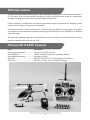
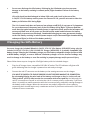
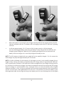
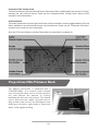
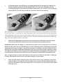
Instruction Manual
Specifications
Length:
Height:
Main Rotor Diameter:
Weight with Battery:
Main Motor:
Tail Motor:
Battery:
Charger:
Transmitter:
On-Board Electronics:
11.6 in (295mm)
4.3 in (110mm)
11.6 in (295mm)
3.2 oz (90g)
N40 (installed)
Micro-Coreless (installed)
500mAh 1S 3.7VLiPo (included)
1S 3.7V LiPo AC (included)
4-channel 2.4GHz (included)
4-in-1 receiver/2 ESCs/mixer/gyro and 2 servos (included)
Table of Contents
Specifications ........................................................................................................................................... 1
Introduction ............................................................................................................................................. 3
Safety Precautions and Warnings ............................................................................................................ 3
FCC Information ....................................................................................................................................... 4
Chronos FP 110 RTF Contents .................................................................................................................. 4
Required to Complete .............................................................................................................................. 5
Before the First Flight Checklist ............................................................................................................... 5
Flight Checklist ......................................................................................................................................... 5
LiPo Battery Warnings and Usage Guidlines ............................................................................................ 6
Charging the LiPo Battery ........................................................................................................................ 7
Installing the Transmitter Batteries .......................................................................................................... 9
Transmitter Details ................................................................................................................................... 9
Proportional Mix Trimmer Knob .............................................................................................................. 10
Transmitter Dual Rates ............................................................................................................................11
Flight Controls and Trimming ................................................................................................................... 12
Installing and Removing the LiPo Flight Battery ....................................................................................... 18
Control Unit Initialization, Arming and Motor Control Test ..................................................................... 18
Motor Control Test ..................................................................................................................................21
Selecting a Flying Area ............................................................................................................................. 22
Flying (General) ....................................................................................................................................... 23
Flying Outdoors .................................................................................................................................... 25
Transmitter and Receiver Binding/Linking ............................................................................................... 26
Warranty, Support and Service ................................................................................................................ 26
Notes .......................................................................................................................................................27
Replacement Parts List ............................................................................................................................ 28
Exploded View Parts Listing .................................................................................................................... 28
Exploded View ........................................................................................................................................ 30
Notes ....................................................................................................................................................... 31
2
Introduction
When you’re ready to make the move from multi-rotor and coaxial to single-rotor heli flying there’s no
better choice than the Ares™ [air-eez] Chronos FP 110. The advanced fixed-pitch and self-stabilizing rotor
head design offers the agility and maneuverability of a single-rotor heli along with the stability of a
coaxial heli so you can learn the basics of more advanced flying with confidence and in less time than
ever before.
The ultra-micro sized Chronos FP 110 is larger than similar class helis for improved performance and
handling when flying outdoors in winds up to 5-7 mph yet it’s still small enough to fly comfortably indoors
too. It’s also equipped with class-leading features including separate 1.7-gram digital servos, a quiet and
efficient two-stage gear train plus a lightweight and durable airframe that arrives 100%
factory-assembled and ready-to-fly right out of the box!
And although the Chronos FP 110 is ready to fly right out the box, please take the time to read through
this manual for more information on battery safety and charging, flight controls and more before
proceeding with your first flight. Please also visit our web site at www.Ares-RC.com for additional
information including potential product bulletins, videos and more.
Safety Precautions and Warnings
Failure to use this product in the intended manner as described in the following instructions can result
in damage and/or personal injury. A Radio Controlled (RC) airplane/helicopter/quadcopter is not a toy!
If misused it can cause serious bodily harm and damage to property.
Keep items that could become entangled in the propeller/rotor blades away from the propeller/rotor
blades, including loose clothing, tools, etc. Be especially sure to keep your hands, face and other parts
of your body away from the propeller/rotor blades.
As the user of this product you are solely and wholly responsible for operating it in a manner that does
not endanger yourself and others or result in damage to the product or the property of others.
This model is controlled by a radio signal that is subject to possible interference from a variety of
sources outside your control. This interference can cause momentary loss of control so it is advisable
to always keep a safe distance from objects and people in all directions around your model as this will
help to avoid collisions and/or injury.
•
•
•
•
•
•
Never operate your model if the voltage of the batteries in the transmitter is too low.
Always operate your model in an open area away from obstacles, people, vehicles, buildings,
etc.
Carefully follow the directions and warnings for this and any optional support equipment
(chargers, rechargeable batteries, etc.).
Keep all chemicals, small parts and all electronic components out of the reach of children.
Moisture causes damage to electronic components. Avoid water exposure to all electronic
components, parts, etc. not specifically designed and protected for use in water.
Never lick or place any portion of the model in your mouth as it could cause serious injury or
even death.
3
FCC Information
This device complies with part 15 of the FCC rules. Operation is subject to the following two conditions:
(1) This device may not cause harmful interference, and (2) this device must accept any interference
received, including interference that may cause undesired operation.
Caution: Changes or modifications not expressly approved by the party responsible for compliance could
void the user’s authority to operate the equipment.
This product contains a radio transmitter with wireless technology which has been tested and found to
be compliant with the applicable regulations governing a radio transmitter in the 2.400GHz to 2.4835GHz
frequency range.
The associated regulatory agencies of the following countries recognize the noted certifications for this
product as authorized for sale and use: USA
Chronos FP 110 RTF Contents
Item
Description
Not Available Separately .................. Chronos FP 110 RTF Airframe
AZSH1258MD2 ................................. M4LPH 4-Channel Helicopter Transmitter, Mode 2
Not Available Separately .................. AA Batteries (6pcs)
AZSH1255 ........................................ 500mAh 1-Cell/1S 3.7V 15C LiPo Battery, JST Connector
AZSH1254 ........................................ 1-Cell/1S 3.7V LiPo, 0.5A 110-240V AC Charger
4
Required to Complete
The Chronos FP 110 RTF includes everything needed to fly right out of the box. There’s nothing extra to
buy or provide!
Before the First Flight Checklist
PLEASE NOTE: This checklist is NOT intended to replace the content included in this instruction
manual. Although it can be used as a quick start guide, we strongly suggest reading through this
manual completely before proceeding.
•
Remove and inspect all contents
•
Plug the AC charger into a suitable outlet/power source
•
Begin charging the LiPo flight battery (connect it to the charger)
•
Install the six (6) AA batteries in the transmitter
•
Install the LiPo flight battery in the helicopter (after it’s been fully charged) and connect it
to the control unit
•
Test the controls to confirm proper operation
•
Familiarize yourself with the controls
•
Find a suitable area for flying
Flight Checklist
PLEASE NOTE: This checklist is NOT intended to replace the content included in this instruction
manual. Although it can be used as a quick start guide, we strongly suggest reading through this
manual completely before proceeding.
•
Always turn the transmitter on first
•
Connect the LiPo flight battery to the control unit
•
Allow the control unit to initialize and arm properly
•
Fly the model (take-off from a flat/level surface)
•
Land the model (land on a flat/level surface)
•
Disconnect the LiPo flight battery from the control unit
•
Always turn the transmitter off last
5
LiPo Battery Warnings and Usage Guidelines
IMPORTANT NOTE: Lithium Polymer batteries are significantly more volatile than the alkaline, NiCd or
NiMH batteries also used in RC applications. All instructions and warnings must be followed exactly to
prevent property damage and/or personal injury as mishandling of LiPo batteries can result in fire.
By handling, charging or using the included LiPo battery you assume all risks associated with LiPo
batteries. If you do not agree with these conditions please return the complete product in new, unused
condition to the place of purchase immediately.
And although the 500mAh 1-Cell/1S 3.7V 15C LiPo Battery (AZSH1255) included with the RTF version
Chronos FP 110 is intended to be charged safely using the included 1-Cell/1S 3.7V LiPo, 0.5A 110-240V
AC Charger (AZSH1254) you must read the following safety instructions and warnings before handling,
charging or using the LiPo battery.
•
You must charge the LiPo battery in a safe area away from flammable materials.
•
Never charge the LiPo battery unattended at any time. When charging the battery you should
always remain in constant observation to monitor the charging process and react immediately
to any potential problems that may occur.
•
After flying/discharging the battery you must allow it to cool to ambient/room temperature
before recharging.
•
To charge the LiPo battery you must use only the included 1-Cell/1S 3.7V LiPo, 0.5A 110-240V AC
Charger (AZSH1254) or a suitably compatible LiPo battery charger. Failure to do so may result in
a fire causing property damage and/or personal injury. DO NOT use a NiCd or NiMH charger.
•
If at any time during the charge or discharge process the battery begins to balloon or swell,
discontinue charging or discharging immediately. Quickly and safely disconnect the battery,
then place it in a safe, open area away from flammable materials to observe for at least 15
minutes. Continuing to charge or discharge a battery that has begun to balloon or swell can
result in a fire. A battery that has ballooned or swollen even a small amount must be removed
from service completely.
•
Store the battery at room temperature, approximately 68–77° Fahrenheit (F), and in a dry area
for best results.
•
When transporting or temporarily storing the battery, the temperature range should be from
approximately 40–100°F. Do not store the battery or model in a hot garage, car or direct
sunlight whenever possible. If stored in a hot garage or car the battery can be damaged or even
catch fire.
6
•
Do not over-discharge the LiPo battery. Discharging the LiPo battery too low can cause
damage to the battery resulting in reduced power, flight duration or failure of the battery
entirely.
LiPo cells should not be discharged to below 3.0V each under load. In the case of the
1-Cell/1S 3.7V LiPo battery used to power the Chronos FP 110, you will not want to allow the
battery to fall below 3.0V during flight.
The 4-in-1 control unit does not feature a low voltage cutoff (LVC) of any type so it’s important
for you to be aware of the power level of the LiPo battery during flight. If you ever find that
more than the typical amount of throttle/power is required to hover and/or the helicopter will
not ascend/climb even at full power you should land the model and disconnect the battery
immediately to prevent over-discharge. Continued discharging can cause permanent damage
to the LiPo battery resulting in reduced power output and/or shortened flight durations during
subsequent flights (or failure of the battery entirely).
Charging the LiPo Battery
You must charge the included 500mAh 1-Cell/1S 3.7V 15C LiPo Battery (AZSH1255) using only the
included 1-Cell/1S 3.7V LiPo, 0.5A 110-240V AC Charger (AZSH1254) or a suitably compatible LiPo
battery charger. Charging the LiPo battery using a non-LiPo battery compatible charger (such as a NiCd
or NiMH battery charger), or even a different LiPo battery charger w ith the incorrect settings, may
result in damage to the battery or even fire resulting in property damage and/or personal injury.
Please follow these steps to charge the LiPo flight battery with the included charger:
•
Plug the AC charger into a compatible 110-240V AC outlet. The LED indicator will glow solid
green indicating that the charger is powered on and ready to charge.
•
Connect the red JST connector on the battery to the mating connector on the charger.
YOU MUST BE CAREFUL TO ENSURE PROPER POLARITY BEFORE MAKING THE CONNECTION.
By orientating/aligning the wire leads of the battery and charger so they’re ‘red to red’ and
‘black to black’ you’ll be able to make the connection with correct polarity. And although the
red JST connectors are ‘keyed’ to minimize the risk of a reverse polarity connection, if you force
them it is possible to make connection with the incorrect polarity potentially causing damage to
the battery and/or charger. When the connectors are properly aligned for correct polarity,
connecting them should require only a moderate amount of pressure to achieve the ‘click’ that
indicates a secure connection.
7
•
When the battery is connected to the charger securely and with the proper polarity the LED
indicator will glow solid red. The battery will be charging anytime the LED indicator is glowing
solid red.
•
It will take approximately 1.0–1.5 hours to fully charge a mostly or fully discharged
(not over-discharged) battery. And when the battery is fully charged the LED indicator will
change to glow solid green. When the LED is glowing solid green you can disconnect the
battery from the charger as it is now fully charged and ready for use.
NOTE: The LiPo battery included with your model will arrive partially charged. For this reason the
initial charge may only take approximately 30–45 minutes.
NOTE: It’s safer and better for the longevity of the battery to store it only partially charged for any
length of time. Storing the battery at approximately 50% charge (which is approximately 3.85V per
cell) is typically best, however, it will take some careful management of the charge time and the use
of a volt meter to achieve this voltage. If you have the equipment and skills to achieve the 50% charge
level for storage it is recommended. If not, simply be sure to not store the battery fully charged
whenever possible. In fact, as long as the battery will be stored at approximately room temperature
and for no more than a few weeks before the next use, it may be best to store the battery in the
discharged state after the last flight (as long as the battery was not over-discharged on the last flight).
8
Installing Transmitter Batteries
Install the six included AA batteries in the back of the transmitter by removing the screw securing the
battery compartment cover/door then remove the battery compartment cover/door. Ensure proper
polarity of the batteries before installing them as indicated by the markings molded into the battery
compartment, then re-install the compartment cover/door and screw.
Check for proper operation of the transmitter by switching the power switch ON (slide it upward). The
LED indicator near the top right-hand corner should glow solid red while the LCD screen powers on to
display various data. These indications confirm the transmitter is powered on and functioning correctly.
NOTE: The transmitter is equipped with a low voltage battery alarm. If at any time the audible alarm is
on it will be necessary to replace the AA batteries with new ones.
Transmitter Details
The Chronos FP 110 includes an M4LPH Micro 4-Channel Helicopter Transmitter equipped with 2.4GHz
technology, dual rates, digital trims and an LCD screen.
9
Proportional Mix Trimmer Knob
The knob located near the top left-hand corner of the transmitter is used to adjust the amount of ‘mixing’
between the main and tail motors. Please see the ‘Proportional Mix Trimmer Knob’ section of this
manual for more information.
Dual Rate Button
The button located near the top right-hand corner of the transmitter is used to toggle between the ‘Dual
Rates’ available for the aileron and elevator controls/channels. Please see the ‘Transmitter Dual Rates’
section of this manual for more information.
Also, the LCD screen displays a variety of data when the transmitter is powered on:
Proportional Mix Trimmer Knob
The M4LPH transmitter is equipped with a
‘PROPORTIONAL’ mix trimmer knob (located
near the top left-hand corner of the transmitter) that adjusts the amount of ‘mixing’
between the main and tail motors. This allows
you to fine-tune the rudder trim/sub-trim to
help prevent the nose of the helicopter from
drifting to the left or right when in hover and
when climbing/descending.
10
NOTE: All Chronos FP 110 helicopters are test-flown at the factory. And during each test flight the
position/setting for the proportional mix trimmer knob is typically adjusted to provide very good trim
and performance overall. However, it is possible for the position of the knob to change during handling
of the transmitter so it may be necessary to adjust the position/setting of the knob to achieve the best
possible trim and performance. And if you find it necessary to adjust the position/setting of the knob
please follow these steps:
•
Establish a stable hover and, with the rudder trim ‘centered’ and no rudder control input, check
to see if the nose of the helicopter is drifting in one direction or the other. If the nose of the
helicopter is drifting to the left, turn the proportional mix trimmer knob clockwise (+) as needed
to minimize/eliminate the drifting.
•
If the nose of the helicopter is drifting to the right, turn the proportional mix trimmer knob
counterclockwise (-) as needed to minimize/eliminate the drifting.
QUICK TIP: As the motors heat up and the battery’s output voltage decreases throughout the flight, it
may be necessary to adjust the rudder trim position/setting slightly to keep the nose of the helicopter
from drifting to the left or right. These small adjustments can be made using the rudder trim and do
not typically require additional adjustment of the proportional mix trimmer knob.
Transmitter Dual Rates
The ‘DUAL RATE’ button (located near the top
right-hand corner of the transmitter) is used to the
toggle between the ‘High’ (HI) and ‘Low’ (LO)
control rates, also known as ‘Dual Rates’, available
for the aileron and elevator controls/channels.
When the LED indicator is ON and glowing solid red
the control rate is set to ‘HI’ and the controls are
allowed to reach their maximum (high)
rates/values. This mode is typically preferred by
experienced pilots interested most in maximum
control authority.
When the LED indicator is OFF the control rate is set to ‘LO’ and the maximum control rates/values will
be reduced for the aileron and elevator channels. This is typically preferred by (and recommended best
for) low-time and other pilots interested in a reduced amount of control authority that allows for even
smoother and more easily controlled hovering/flying.
NOTE: Each time the transmitter is powered off then on again the dual rates will default to HI.
11
Flight Controls and Trimming
In the event you are not familiar with the controls of the Chronos FP 110 please take the time to
familiarize yourself with them as follows and before proceeding with your first flight:
The left-hand stick on the transmitter controls both the throttle (climb/descend) and rudder (yaw
left/right) channels. When the left-hand stick (also known as the ‘throttle’ stick) is in the lowest possible
position the rotor blades will not spin. Moving the stick upward will increase the speed/RPMs of the rotor
blades. Increasing the speed/RPMs of the rotor blades will cause the model to climb.
Decreasing the speed/RPMs of the rotor blades by lowering the left-hand stick will cause the model to
descend.
After lifting the helicopter off the ground you can maintain altitude in ‘hover’ by carefully moving the
left-hand stick up and down slightly as needed so the helicopter will not climb or descend.
12
The throttle trim lever (located immediately to the right of the left-hand/throttle stick) can be used to
adjust the throttle control/channel output value for a given stick position. For example, raising the throttle
trim will make it possible to maintain altitude with the helicopter when the left-hand/throttle stick is in a
lower position. However, we do not typically recommend raising or lowering the throttle trim above/below
the middle/centered position.
IMPORTANT NOTE: If you do raise the throttle trim you
MUST remember to lower it to the middle/centered
position AND the throttle stick to the lowest possible
position IMMEDIATELY in the event of a crash or rotor
blade strike. Failure to lower the throttle trim to the
middle/centered position and throttle stick to the lowest
possible position immediately in the event of a crash/rotor
blade strike can result in damage to the ESCs in the 4-in-1
control unit (which may require replacement of the control
unit).
Moving the left-hand stick to the left will turn (yaw) the nose of the helicopter to the left about the axis of
the main shaft. This is accomplished by decreasing the speed/RPMs of the tail rotor.
13
Moving the left-hand stick to the right will turn (yaw) the nose of the helicopter to the right about the
axis of the main shaft. This is accomplished by increasing the speed/RPMs of the tail rotor.
The rudder trim lever (located immediately below the left-hand stick) can be used to help keep the nose
of the helicopter from turning (yawing) to the left or right when ‘hovering’ and without any left-hand
stick/rudder control input. For example, if the nose of the helicopter turns to the right when hovering
add left rudder trim by pressing the lever to the left until the nose of the helicopter stays as close to
‘straight’ as possible with no further rudder control/trim input.
NOTE: It is not uncommon for the nose of most FP (Fixed-Pitch) helicopters with a tail motor to drift
slightly in one direction or the other throughout a flight (as the motors heat up and the battery’s output
voltage decreases). This means you may find it necessary to adjust the rudder trim position/setting
slightly throughout a flight but typically it’s not more than a few ‘clicks’ of trim one way or the other.
Also, please see the ‘Proportional Mix Trimmer Knob’ section of this manual for more information on
other potential adjustments that can be made to fine-tune rudder/tail control and response.
14
The right-hand stick controls both the elevator (pitch fore/aft) and aileron (roll) channels. Pushing the
stick forward will pitch the nose of the helicopter downward, allowing it to be flown forward. This is
accomplished by having the elevator (right-hand) servo pull the swashplate downward.
Pulling the right-hand stick backward will pitch the tail of the helicopter downward, allowing it to be
flown backward. This is accomplished by having the elevator (right-hand) servo push the swashplate
upward.
The elevator trim lever (located immediately to the left of the right-hand stick) can be used to help keep
the helicopter from drifting forward or backward when hovering and with no right-hand stick/elevator
control input. For example, if the helicopter drifts forward when hovering add back/up elevator trim by
pressing the lever downward until the helicopter hovers as level as possible without drifting forward.
16
Moving the right-hand stick to the left will roll the helicopter to the left, allowing it to be flown to the left.
This is accomplished by having the aileron (left-hand) servo pull the swashplate downward.
Moving the right-hand stick to the right will roll the helicopter to the right, allowing it to be flown to the
right. This is accomplished by having the aileron (left-hand) servo push the swashplate upward.
The aileron trim lever (located immediately below the right-hand stick) can be used to help keep the
helicopter from drifting left or right when hovering and with no right-hand stick/aileron control input. For
example, if the helicopter drifts to the right when hovering add left aileron trim by pressing the lever to
the left until the helicopter hovers as level as possible without drifting to the right.
17
Installing and Removing the LiPo Flight Battery
After the LiPo battery has been fully charged it’s ready to be installed in the helicopter. To install
the battery in the helicopter start by removing the canopy. Next, with the wire leads and connector
of the battery oriented so they point forward (away from the 4-in-1 control unit), place the battery
in the battery holder so the hook-and-loop material on the battery and holder make contact. Then
secure the battery in the holder by wrapping the included hook-and-loop strap around the battery
and holder.
To remove the LiPo flight battery (after carefully disconnecting it from the 4-in-1 control unit) start
by removing the canopy and the hook-and-loop strap. Then remove it from the battery
holder/helicopter completely.
Control Unit Initialization, Arming and Motor Control Test
The Chronos FP 110 is equipped with a compact and advanced 4-in-1 control unit. The control unit is a
lightweight combination of 2.4GHz receiver, two electronic speed controls (ESCs), a mixer and gyro.
The control unit is also equipped with LEDs that provide various indications.
The following checklist includes the steps you must follow to ensure proper initialization, arming and
operation of the control unit:
18
•
Before each flight you must ALWAYS turn the transmitter on BEFORE connecting the LiPo
flight battery to the control unit. Never connect the battery to the control unit before
powering the transmitter on first. And after each flight you should always disconnect the
battery from the control unit before turning the transmitter off.
•
The left-hand/throttle stick must be set in the lowest possible position in order for the
control unit to arm properly. Failure to lower the stick to the lowest possible position can
prevent the ESCs from arming and/or the gyro from initializing properly.
•
With the throttle stick in the lowest possible position ensure that the left-hand stick is
‘centered’ left to right and that the right-hand stick is ‘centered’ left to right as well as up
and down and do NOT move the sticks as you turn the transmitter on to avoid changing the
proper center/neutral positions of the controls.
IMPORTANT NOTE: Moving the control sticks while turning the transmitter on can change
the proper center/neutral positions of the controls making it difficult to control the
model and impossible to ‘trim it out’ correctly. And if you ever find this to be the case
then simply disconnect the LiPo flight battery from the 4-in-1 control unit, turn the
transmitter off then follow the steps to properly turn on and initialize the transmitter and
control unit.
•
•
Turn the transmitter on and confirm that the LED indicator near the top right-hand corner
glows solid red while the LCD screen powers on.
NOTE: If this will be the first flight, or the first flight following repairs, you should ‘center’
the rudder, elevator and aileron channel trims.
AFTER INSTALLING THE BATTERY IN THE MOUNT/HELICOPTER YOU MUST BE CAREFUL TO
ENSURE PROPER POLARITY BEFORE CONNECTING IT TO THE 4-IN-1 CONTROL UNIT. By
orienting/aligning the wire leads of the battery and control unit so they’re ‘red to red’
and ‘black to black’ you’ll be able to make the connection with correct polarity.
19
•
AFTER INSTALLING THE BATTERY IN THE MOUNT/HELICOPTER YOU MUST BE CAREFUL TO
ENSURE PROPER POLARITY BEFORE CONNECTING IT TO THE 4-IN-1 CONTROL UNIT. By
orienting/aligning the wire leads of the battery and control unit so they’re ‘red to red’ and
‘black to black’ you’ll be able to make the connection with correct polarity.
Also, although the ‘JST’ connectors are ‘keyed’ to minimize the risk of a reverse polarity connection,
if you force them it is possible to make connection with incorrect/reversed polarity potentially
causing damage to the control unit and/or battery. When the connectors are properly aligned for
correct polarity, connecting them should require only a minimal amount of pressure to achieve the
light ‘click’ that indicates secure connection.
•
With the LiPo flight battery connected to the control unit the LED indicator (on the control
unit) will typically blink red slowly then blink red rapidly before glowing solid red.
IMPORTANT NOTE: after the battery is connected to the control unit it’s important to not move or
ROTATE the helicopter once the RED LED begins to blink confirming that the initialization process and
calibration of the gyro has begun. If you do move/rotate the helicopter too much while the LED is
blinking red it may affect initialization/calibration of the gyro which could require significant rudder
trim adjustments and/or prevent the gyro from working during the pending flight. If this happens you
must disconnect the battery from the control unit and repeat the initialization/calibration process.
Also, it’s typically best to connect the battery to the control unit while the helicopter is sitting on
a stable, flat and level surface rather than when holding it in your hands.
•
When the LED indicator begins to glow solid red the control unit is initialized, armed and
ready for flight. Use caution as the rotor blades will now spin with left-hand/throttle stick
input! Do not advance/raise the throttle stick or trim until you are clear of the rotor blades
and ready to fly.
20
In case the LED indicator does not glow solid red:
•
If the LED indicator continues to blink red slowly you do not have a positive RF link between
the transmitter and receiver. First, check to be sure that the transmitter is powered on and that it
has an adequate level of battery voltage/power. If the transmitter is already powered on,
disconnect the battery from the control unit then turn the transmitter off. Follow the steps to
bind/link the transmitter to the receiver/4-in-1 control unit (see the ‘Transmitter and Receiver
Binding/Linking’ section of this manual and after confirming that the transmitter and receiver are
properly bound/linked, connect the battery to the control unit again. The LED indicator should blink
red rapidly, blink red slowly then glow solid red to indicate the control unit is initialized, armed and
ready for flight.
After confirming the control unit has initialized and armed properly the Chronos FP 110 is ready to
fly. However, please review the following information/sections of the manual BEFORE proceeding
with your first flight.
Motor Control Test
To confirm proper control and operation of the motors place the helicopter in an open area free of
people and obstructions. And when everything is clear of the main and tail rotor blades, proceed with
the following steps:
•
•
Raise the left-hand/throttle stick slowly and just high enough so that both the main and tail
rotor blades begin to spin slowly. Then, note the direction that the rotor blades spin. The main
rotor blades should spin clockwise and the tail rotor blade should spin counterclockwise (when
viewed from directly from the top and right side of the helicopter).
•
The main motor spins the main rotor blades and should be connected to the larger
connector on the control unit.
•
The tail motor spins the tail rotor blade and should be connected to the smaller
connector on the control unit.
After confirming that the main and tail rotors are spinning in the correct directions it’s
important to confirm that the tail rotor responds properly to rudder (yaw) control inputs. With
the main and tail rotors spinning slowly move the left-hand/rudder stick to the right. This
should cause the speed/RPMs of the tail rotor to increase. Next, move the left-hand/rudder
stick to the left. This should cause the speed/RPMs of the tail rotor to decrease.
21
Selecting a Flying Area
Before proceeding with your first flights indoors or out please be sure to review the details in this
section to ensure you’re choosing suitable spaces and conditions to achieve the best possible
performance and flying experience.
IMPORTANT NOTE: If you are a first-time or low-time pilot we strongly recommend allowing a more
experienced pilot to test fly and properly trim the model before attempting your first flight. A proven
flyable and properly trimmed model is significantly easier and more enjoyable to fly! Please contact
your local hobby shop and/or flying club to find a more experienced pilot near you.
Indoor Flying Areas
When flying indoors you’ll want to select an open area free of people and obstructions. We suggest an
area with at least 12-feet by 12-feet of floor space and no less than 8-foot ceilings when making your
first few flights.
After you’ve properly trimmed the helicopter and become familiar with its handling and capabilities
you may be able to fly in other smaller and less open areas too. However, it’s always more fun to fly
indoors in spaces that are larger and/or more open when possible.
Outdoor Flying Areas/Conditions
When flying outdoors it’s best to fly the Chronos FP 110 at a local park, schoolyard or other area that’s
large enough and free of people and obstructions. We also suggest flying over grass as it’s a much
more ‘forgiving’ surface that causes less damage in the unfortunate event of a crash. DO NOT fly in
parking lots, crowded neighborhood areas or in areas that are not free of people and obstructions.
Also, it’s typically best to fly on days that are calm/with no wind, especially when making your first few
flights. We strongly suggest flying only in calm conditions until you’re familiar with the controls and
handling of the model. Even light winds can make it much more difficult to fly, and in some cases can
even carry the model beyond your line of sight.
After you’ve properly trimmed the helicopter in calm conditions and become familiar with its
handling/capabilities it can be flown outdoors in light wind conditions. Please see the ‘Flying
Outdoors’ section of this manual for more information.
IMPORTANT NOTE: Do NOT fly on days when significant moisture, such as rain or snow, is present!
22
Flying (General)
Now that you’ve selected a suitable flying area you’re ready to fly! And when making your first
flights we suggest following these steps:
•
Slowly raise the left-hand/throttle stick to increase the speed of the main rotor blades and
until the model begins to lift off. Do NOT raise the stick too quickly as the model could
climb too fast causing you to lose control and/or make contact with the ceiling or other
objects above (this is one of the most common ways for many pilots to crash the first
time!).
•
Lift the model approximately 20–24 inches (50–60 centimeters) off the ground and
concentrate on ‘balancing’ the throttle stick position so the helicopter holds a steady hover
altitude. It may also be helpful to make a few short ‘hops’ to an altitude of just a few inches
until you’re familiar and more comfortable with the control inputs and trim settings
required to maintain a steady hover and altitude. However, keep in mind that when only a
few inches off the ground you’ll be in ‘ground effect’ which will cause the helicopter to
move around more than it typically would at approximately 20–24 inches of altitude.
•
You’ll find that it sometimes takes minor throttle adjustments to maintain altitude in hover.
Remember to keep these adjustments as minimal as possible as large adjustments could
result in a loss of control and/or a possible crash.
•
While attempting to establish a low-level hover out of ground effect (approximately 20–24
inches high or higher) you can check to see if any trim adjustments are required to help
keep the helicopter from constantly drifting in various directions. If you find that the
helicopter constantly drifts without any directional control input it may be best to land the
model before making any adjustments to the trim settings using the trim levers on the
transmitter (you can find more information regarding the location and function of the trim
in the ‘Flight Controls and Trimming’ section of this manual):
o
If the nose of the helicopter is drifting to the left or right adjust the rudder trim.
You can also adjust the proportional mix trimmer knob on the transmitter (please see
the ‘Proportional Mix Trimmer Knob’ section of this manual for more information).
o
If the helicopter is drifting forward or backward adjust the elevator trim.
o
If the entire helicopter is drifting to the left or right adjust the aileron trim.
It’s important to continue making trim adjustments as needed until the helicopter can hover at an
altitude of approximately 20–24 inches (or higher) with very little drifting or directional control
input. And while it’s not possible to eliminate all drifting completely using the trims it is possible to
get very close. Also, if this is your first FP (Fixed-Pitch) helicopter model it may be best to enlist the
help of an experienced pilot to trim the model for you before making your first flight.
23
•
When the helicopter is properly trimmed, maintain a stable hover and practice using the
rudder, elevator and aileron controls to get a feel for how the helicopter responds to various
control inputs. Remember to keep the control inputs as minimal as possible to prevent
over-controlling the helicopter.
•
Continue to practice until you’re comfortable hovering the helicopter at approximately
20–24 inches of altitude. Then you can transition to hovering the helicopter at higher
altitudes of approximately 3–4 feet (0.9–1.2 meters).
•
If at any time during flight you feel like the helicopter is drifting out of/beyond your
control, simply release all of the controls except for throttle. The throttle will be needed
to maintain altitude, but due to the inherent stability of the self-stabilizing rotor head
design, releasing all of the other controls will allow the helicopter to return to a stable
hover on its own (given enough time and space).
•
IN THE UNFORTUNATE EVENT OF A CRASH OR ROTOR BLADE STRIKE, NO MATTER HOW
MAJOR OR MINOR, YOU MUST LOWER THE THROTTLE STICK TO THE LOWEST POSSIBLE
POSITION AND THE THROTTLE TRIM TO THE MIDDLE/CENTERED POSITION AS QUICKLY AS
POSSIBLE TO PREVENT DAMAGE TO THE ESCS OF THE CONTROL UNIT.
If you do not lower the throttle stick to the lowest possible position and trim to the
middle/centered position in the event of a crash/rotor blade strike it can result in damage to the
ESCs of the control unit which may require replacement of the control unit.
NOTE: Crash damage is not covered under warranty.
•
Once you’ve gained the experience and confidence in hovering your helicopter you can
attempt more advanced maneuvers including:
Forward Flight
Pirouettes
Skidding Landings
Backward Flight
Skidding Takeoffs
Spot Landings
24
Flying Outdoors
The Chronos FP 110 is larger than other similar class models for improved visibility and performance
when flying outdoors in winds up to 5-7 mph.
Hints and Tips
•
Although the Chronos FP 110 can be flown successfully in winds up to 5-7 mph we do not
recommend that all pilots fly in the wind, especially first-time and low-time FP heli pilots.
This is because more experience is typically required to maneuver/fly the helicopter
successfully in the wing. Also, we do not recommend attempting to fly the Chronos FP 110
in any winds higher speed/stronger than 5-7mph.
•
The Chronos FP 110 is larger and more capable of flying outdoors in wind than most other
similar class models, however, there are some traits inherent due to the self-stabilizing rotor
head design that pilots should always keep in mind. It will take some practice for most pilots,
even those with experience flying other FP (Fixed-Pitch) and CP (Collective-Pitch) helicopters,
to identify and better understand all of these traits but here are the most important ones to
keep in mind:
o
Due to the fixed-pitch rotor blade design most pilots will find that it takes some
‘balancing’ of the throttle/power output and the ‘angle’ the helicopter
ispitched/banked at to maintain speed and altitude during forward/backward/sideways
flight. This is especially true when flying directly into the wind, and in some cases it will
not be possible to fly directly into/penetrate the wind at a reasonable ground speed
without gaining altitude (this trait is also inherent in most single-rotor FP helicopters).
o
Also due to the fixed-pitch rotor blade design it will take some practice to find the best
balance of throttle/power output and other controls to descend/lose altitude without
decreasing the speed/RPMs of the rotor blades too much (if the speed/RPMs decrease
too much the helicopter can lose altitude too quickly and/or become unstable resulting
in a crash). This is especially true when trying to descend/lose altitude whether flying
into (upwind), with (downwind) or sideways in the wind (this trait is also inherent in
most single-rotor FP helicopters).
o
Due to the inherent stability and self-leveling capability of the rotor head design you
may sometimes find that it’s better to allow the flybar and/or helicopter to more
‘naturally’ return closer to ‘level’ before attempting to change direction during
forward/backward/sideways flight, especially when flying in wind.
For example if you’re flying forward and want to switch to flying backward it may be helpful to
‘neutralize’ the aileron and/or elevator controls then watch/allow the flybar to change from a more
‘forward’ angle to closer to ‘level’ before changing the direction of the helicopter by giving
backward/up elevator control input. Otherwise the flybar may ‘over-rotate’ and become ineffective
causing a loss of stability (and possibly causing the flybar to come into contact with the canopy and/or
tail boom).
25
Transmitter and Receiver Binding/Linking
Binding/linking is the process of programming the receiver to recognize the Globally Unique Identifier
(GUID) code of a single specific transmitter. These steps outline the binding/linking process of the
M4LPH 4-Channel Helicopter Transmitter (AZSH1258) and receiver/control unit:
•
Provide power to the 4-in-1 control unit by connecting the flight battery.
•
If the receiver/control unit is not bound/linked to the transmitter the red LED indicator
will blink slowly. This indicates the receiver/4-in-1 control unit has entered bind/link
mode.
While the receiver/control unit is in bind/link mode turn the transmitter on. Each time the
transmitter is turned on it will automatically enter the bind/link mode briefly as indicated by the
audible beeps/tone. After a few seconds it will stop emitting the audible beeps/tone indicating
that the binding/linking process is complete. Also, during the binding/linking process the LED
indicator on the receiver will blink slowly then switch to glow solid red when the process is
complete. You should now have full control of the receiver/control unit/servos (if you do not
have control repeat all steps of the binding/linking process again).
•
•
After approximately 8-10 seconds the LED indicator on the 4-in-1 control unit will begin to glow
solid red indicating the binding/linking process is complete. You should now have full control of
the receiver/ESC/servos.
Warranty, Support and Service
30-Day Limited Warranty Term Period:
We warranty that the Product(s) purchased (the “Product”) will be free from defects in materials and
work¬manship when the product is new (before being used) for the limited warranty term period, 30
days, from the date of purchase by the Purchaser.
If you believe a defect in material, workmanship, etc. was not apparent when the Product was new
and only became evident after the Product was used, take the following steps. If you purchased the
Product at a HobbyTown store, please contact your local HobbyTown store for warranty support and/
or service. If you purchased the Product from the Firelands website, use the contact information
found under the Support heading to contact Firelands directly.
If you contact Firelands, you may be asked to send the product to Firelands, at your cost, for
inspection. Provided the warranty conditions have been met within the warranty term period, the
components that are found to be defective, incorrectly manufactured or assembled may be repaired
or replaced, at the sole discretion of Firelands. Your warranty item will be returned to you at
Firelands’ expense. In the event your product needs repair or a replacement part that is not covered
by this warranty, your local HobbyTown store or Firelands can assist you with support and in
obtaining the genuine replacement parts to repair your Prod¬uct. Firelands will charge $40.00 per
hour plus the cost of replacement parts to service your vehicle if after contacting you, you so
authorize such repairs. Your product will be returned to you at your expense.
If you purchased your Product from a HobbyTown Internet site not affiliated with a local store, please
consult that site for its support and service policies. You can also find more information at
www.Hobbytown.com., by emailing [email protected] or call 800-205-6773
26
Notes
________________________________________________________________________________
________________________________________________________________________________
________________________________________________________________________________
________________________________________________________________________________
________________________________________________________________________________
________________________________________________________________________________
________________________________________________________________________________
________________________________________________________________________________
________________________________________________________________________________
________________________________________________________________________________
________________________________________________________________________________
________________________________________________________________________________
________________________________________________________________________________
________________________________________________________________________________
________________________________________________________________________________
________________________________________________________________________________
________________________________________________________________________________
________________________________________________________________________________
________________________________________________________________________________
________________________________________________________________________________
________________________________________________________________________________
________________________________________________________________________________
________________________________________________________________________________
________________________________________________________________________________
________________________________________________________________________________
________________________________________________________________________________
________________________________________________________________________________
________________________________________________________________________________
________________________________________________________________________________
________________________________________________________________________________
________________________________________________________________________________
________________________________________________________________________________
________________________________________________________________________________
________________________________________________________________________________
________________________________________________________________________________
________________________________________________________________________________
________________________________________________________________________________
________________________________________________________________________________
________________________________________________________________________________
________________________________________________________________________________
________________________________________________________________________________
________________________________________________________________________________
________________________________________________________________________________
________________________________________________________________________________
27
Replacement Parts List
Item Number
AZSH1254
AZSH1255
AZSH1256
AZSH1257L
AZSH1257R
AZSH1257AS
AZSH1257GS
AZSH1258MD2
AZSH1259
AZSH1260
AZSH1261
AZSH1262
AZSH1263
AZSH1264
AZSH1265
AZSH1266
AZSH1267
AZSH1268
AZSH1269
AZSH1270
AZSH1271
AZSH1272
AZSH1273
AZSH1274
Description
1-Cell/1S 3.7V LiPo, 0.5A 110-240V AC Charger: Chronos FP 110
500mAh 1-Cell/1S 3.7V 15C LiPo Battery, JST Connector: Chronos FP 110
4-in-1 Control Unit, Rx/ESCs/Mixer/Gyro: Chronos FP 110
1.7-Gram Digital Servo, Left: Chronos FP 110
1.7-Gram Digital Servo, Right: Chronos FP 110
1.7-Gram Digital Servo Arm Set: Chronos FP 110
1.7-Gram Digital Servo Gear Set: Chronos FP 110
M4LPH Micro 4-Channel LP Helicopter Transmitter, Mode 2: Chronos FP 110
Main Motor with Pinion Gear: Chronos FP 110
Flybar: Chronos FP 110
Rotor Head Linkage Set: Chronos FP 110
Main Rotor Blade Grip and Mixing Arm Set (1 pair): Chronos FP 110
Main Rotor Blade Set (1 pair): Chronos FP 110
Main Shaft with Rotor Head/Hub: Chronos FP 110
Main Gear Set: Chronos FP 110
Bearing, 3x6x2.5mm (2pcs): Chronos FP 110
Swashplate: Chronos FP 110
Servo Pushrod Set: Chronos FP 110
Main Frame Set: Chronos FP 110
Tail Motor, Mount, Gear, Fin and Boom Assembly: Chronos FP 110
Tail Rotor Blade: Chronos FP 110
Vertical Fin: Chronos FP 110
Landing Gear/Battery Holder Set: Chronos FP 110
Canopy: Chronos FP 110
Exploded View Parts Listing
Exploded View #
1
2
3
4
5
6
7
8
9
10
11
12
Description (Total Quantity Used)
Body/Canopy (1)
Battery (1)
M1.4x5mm Screw (4)
4-in-1 Control Unit (1)
M1.2x3mm Screw (2)
Servo Arm (2)
Servo Pushrod (2)
Ball Link (2)
Body/Canopy Mount (2)
M1.4x4x4mm Screw (4)
Servo, Left (1)
Servo, Right (1)
28
Included In Item #
AZSH1274
AZSH1255
AZSH1256 or AZSH1270
AZSH1256
AZSH1257AS
AZSH1257AS
AZSH1268
AZSH1268
AZSH1269
AZSH1257L or AZSH1257R
AZSH1257L
AZSH1257R
Exploded View #
13
14
15
16
17
18
19
20
21
22
23
24
25
26
27
28
29
30
31
32
33
34
35
36
37
38
39
40
41
42
43
44
45
46
47
48
49
Description (Total Quantity Used)
M1.7x6mm Screw (12)
Motor (1)
M1.4x2.5mm Screw (5)
Main Shaft Retaining Collar (1)
Main Shaft (1)
Feathering Spindle (1)
Swashplate Assembly (1)
Main Rotor Head/Hub (1)
M1.7x6mm Screw (12)
Main Rotor Blade Grip, Lower Part (2)
M1.7x6mm Screw (12)
Rotor Head Linkage, Long (2)
Rotor Head Linkage, Short (2)
Main Rotor Blade/Head Mixing Arm (2)
M1.7x6mm Screw (12)
Main Rotor Blade (2)
Main Rotor Blade Grip, Upper Part (2)
Flybar (1)
M1.4x2.5mm Screw (5)
Tailboom (1)
M1.4x2.5mm Screw (5)
Vertical Fin (1)
Tail Rotor Blade (1)
M1.7x4x5mm Screw (1)
Tail Motor, Mount, Gear Assembly (1)
M1.4x5mm Screw (4)
M1.4x2.5x3.5mm Screw (2)
Pinion (1)
Intermediate Gear (1)
Intermediate Gear Shaft (1)
Main Gear (1)
M1.5x7mm Screw (1)
Landing Gear/Battery Holder (1)
Landing Skid (2)
M1.7x6mm Screw (12)
M1.2x3mm Screw (4)
Bearing, 3x6x2.5mm (2)
29
Included In Item #
AZSH1269 or AZSH1273
AZSH1259
AZSH1264 or AZSH1270
AZSH1264
AZSH1264
AZSH1262
AZSH1267
AZSH1264
AZSH1262 or AZSH1273
AZSH1262
AZSH1262 or AZSH1273
AZSH1261
AZSH1261
AZSH1262
AZSH1262 or AZSH1273
AZSH1263
AZSH1262
AZSH1260
AZSH1264 or AZSH1270
AZSH1270
AZSH1264 or AZSH1270
AZSH1270 or AZSH1272
AZSH1271
AZSH1271
AZSH1270
AZSH1270
AZSH1259
AZSH1259
AZSH1265
AZSH1265
AZSH1265
AZSH1264 or AZSH1265
AZSH1273
AZSH1273
AZSH1262 or AZSH1273
AZSH1273
AZSH1266
Exploded View
30
Notes
________________________________________________________________________________
________________________________________________________________________________
________________________________________________________________________________
________________________________________________________________________________
________________________________________________________________________________
________________________________________________________________________________
________________________________________________________________________________
________________________________________________________________________________
________________________________________________________________________________
________________________________________________________________________________
________________________________________________________________________________
________________________________________________________________________________
________________________________________________________________________________
________________________________________________________________________________
________________________________________________________________________________
________________________________________________________________________________
________________________________________________________________________________
________________________________________________________________________________
________________________________________________________________________________
________________________________________________________________________________
________________________________________________________________________________
________________________________________________________________________________
________________________________________________________________________________
________________________________________________________________________________
________________________________________________________________________________
________________________________________________________________________________
________________________________________________________________________________
________________________________________________________________________________
________________________________________________________________________________
________________________________________________________________________________
________________________________________________________________________________
________________________________________________________________________________
________________________________________________________________________________
________________________________________________________________________________
________________________________________________________________________________
________________________________________________________________________________
________________________________________________________________________________
________________________________________________________________________________
________________________________________________________________________________
________________________________________________________________________________
________________________________________________________________________________
________________________________________________________________________________
________________________________________________________________________________
________________________________________________________________________________
31
Notes
_________________________________________________________________________________
_________________________________________________________________________________
_________________________________________________________________________________
_________________________________________________________________________________
_________________________________________________________________________________
_________________________________________________________________________________
_________________________________________________________________________________
_________________________________________________________________________________
_________________________________________________________________________________
_________________________________________________________________________________
_________________________________________________________________________________
_________________________________________________________________________________
_________________________________________________________________________________
_________________________________________________________________________________
_________________________________________________________________________________
_________________________________________________________________________________
_________________________________________________________________________________
_________________________________________________________________________________
_________________________________________________________________________________
_________________________________________________________________________________
_________________________________________________________________________________
_________________________________________________________________________________
_________________________________________________________________________________
_________________________________________________________________________________
_________________________________________________________________________________
_________________________________________________________________________________
_________________________________________________________________________________
_________________________________________________________________________________
_________________________________________________________________________________
_________________________________________________________________________________
_________________________________________________________________________________
_________________________________________________________________________________
_________________________________________________________________________________
_________________________________________________________________________________
_________________________________________________________________________________
_________________________________________________________________________________
_________________________________________________________________________________
_________________________________________________________________________________
_________________________________________________________________________________
_________________________________________________________________________________
_________________________________________________________________________________
_________________________________________________________________________________
_________________________________________________________________________________
_________________________________________________________________________________
32
www.Ares-RC.com
© 2013
Rev 06.30.13