1
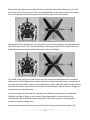
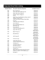
Instruction Manual Specifications Length: Height : Main Rotor Diameter: Weight with Battery: Main Motor: Battery: Charger: Transmitter: On‐Board Electronics: 7.3 in (185mm) 3.5 in (90mm) 6.9 in (175mm) 0.7 oz (21 g) Micro coreless (2 installed) 110mAh 1S 3.7V LiPo (included) 1S 3.7V LiPo (in transmitter, included) 3‐channel 2.4GHz w/LiPo charger (included) 4‐in‐1 receiver/2 ESCs/mixer/gyro (installed) 1 Table of Contents Specifications ............................................................................................................................. 1 Introduction ............................................................................................................................... 3 Safety Precautions and Warnings .............................................................................................. 3 FCC Information ......................................................................................................................... 4 Chronos CX 75 RTF Contents ...................................................................................................... 5 Before the First Flight Checklist ................................................................................................. 6 Flight Checklist ........................................................................................................................... 6 Installing the Transmitter Batteries ........................................................................................... 7 Transmitter Details .................................................................................................................... 7 LiPo Battery Warnings and Usage Guidelines ............................................................................ 8 Charging the LiPo Flight Battery ............................................................................................... 10 Flight Controls and Trimming ................................................................................................... 12 Selecting a Flying Area ............................................................................................................. 15 Control Unit Initialization and Arming ..................................................................................... 15 Flying ........................................................................................................................................ 17 Transmitter and Receiver Binding/Linking ............................................................................... 19 Exploded View Parts Listing ..................................................................................................... 20 Exploded View ......................................................................................................................... 21 Replacement Parts List ............................................................................................................. 21 Warranty, Support and Service ................................................................................................ 22 Notes ........................................................................................................................................ 23 2 Introduction The incredible stability and unbelievable durability of the Ares™ [air‐eez] Chronos CX 75 makes it easy and fun for ANYONE to fly an RC helicopter. The coaxial, counter‐rotating blade design offers unsurpassed stability that will have any pilot hovering like a pro in no time while fully proportional controls deliver excellent maneuverability and precise control. The Chronos CX 75’s nano‐micro size and low weight make it possible to fly indoors just about anytime and anywhere. The heli is 100% factory‐assembled and ready‐to‐fly right out of the box plus it really is durable – in fact, it’s nearly unbreakable in most crashes! And, unlike other similar class models, a full‐line of replacement parts is available in the rare case you ever need them. Also in the box is everything needed to fly including AA batteries for the 3‐channel transmitter equipped with 2.4GHz technology, digital trims and a built‐in LiPo battery charger. And the included 110mAh 1S 3.7V LiPo battery delivers plenty of power and long flight times of up to 10+ minutes per charge. That means there’s nothing extra to buy and you can be ready to fly within minutes of opening the box! And while the Chronos CX 75 is ready‐to‐fly right out the box, please take the time to read through this manual for more information on battery safety and charging, flight controls and more before making your first flight. Please also visit our web site at www.Ares‐RC.com for additional information including product updates, bulletins, instructional repair videos and more. Safety Precautions and Warnings Failure to use this product in the intended manner as described in the following instructions can result in damage and/or personal injury. A Radio Controlled (RC) helicopter is not a toy! If misused it can cause serious bodily harm and damage to property. Keep items that could become entangled in the rotor blades away from the main blades, including loose clothing, tools, etc. Be especially sure to keep your hands, face and other parts of your body away from the rotor blades. As the user of this product you are solely and wholly responsible for operating it in a manner that does not endanger yourself and others or result in damage to the product or the property of others. 3 This model is controlled by a radio signal that is subject to possible interference from a variety of sources outside your control. This interference can cause momentary loss of control so it is advisable to always keep a safe distance from objects and people in all directions around your model as this will help to avoid collisions and/or injury. • Never operate your model if the voltage of the batteries in the transmitter is too low. • Always operate your model in an open area away from obstacles, people, vehicles, buildings, etc. • Carefully follow the directions and warnings for this and any optional support equipment (chargers, rechargeable batteries, etc.). • Keep all chemicals, small parts and all electronic components out of the reach of children. • Moisture causes damage to electronic components. Avoid water exposure to all electronic components, parts, etc. not specifically designed and protected for use in water. • Never lick or place any portion of your model in your mouth as it could cause serious injury or even death. FCC Information This device complies with part 15 of the FCC rules. Operation is subject to the following two conditions: (1) This device may not cause harmful interference, and (2) this device must accept any interference received, including interference that may cause undesired operation. Caution: Changes or modifications not expressly approved by the party responsible for compliance could void the user’s authority to operate the equipment. This product contains a radio transmitter with wireless technology which has been tested and found to be compliant with the applicable regulations governing a radio transmitter in the 2.400GHz to 2.4835GHz frequency range. The associated regulatory agencies of the following countries recognize the noted certifications for this product as authorized for sale and use: USA 4 Chronos Item Number CX 75 RTF Contents Description Not Available Separately ............ Chronos CX 75 RTF Airframe Not Available Separately ............ Chronos CX 75 RTF Transmitter Not Available Separately ............ 6 AA Batteries 5 Before the First Flight Checklist PLEASE NOTE: This checklist is NOT intended to replace the content included in this instruction manual. Although it can be used as a quick start guide, we strongly suggest reading through this manual completely before proceeding. Remove and inspect all contents Install the six AA batteries in the transmitter Charge the flight battery in the helicopter (connect the charge lead from the transmitter to the helicopter with the transmitter turned on) Turn the transmitter on first then turn the helicopter on Test the controls to confirm proper operation Familiarize yourself with the controls Find a suitable area for flying Flight Checklist PLEASE NOTE: This checklist is NOT intended to replace the content included in this instruction manual. Although it can be used as a quick start guide, we strongly suggest reading through this manual completely before proceeding. Always turn the transmitter on first Turn the helicopter on (after the transmitter is turned on) Allow the control unit to initialize and arm properly Fly the model (take‐off from a flat/level surface) Land the model (land on a flat/level surface) Turn the helicopter off (before the transmitter is turned off) Always turn the transmitter off last 6 Installing the Transmitter Batteries Install the six included AA batteries in the back of the transmitter by first removing the battery compartment cover/door. Ensure proper polarity of the batteries before installing them as noted by the markings molded into the battery compartment, then re‐install the compartment cover/door. Check for proper operation of the transmitter by sliding the ‘power’ switch to the right. The ‘power’ LED indicator (above the switch) should begin to glow solid red indicating the transmitter is powered on and the AA batteries are installed correctly. Turn the transmitter off by sliding the power switch to the left. Transmitter Details The Chronos CX 75 RTF includes a transmitter equipped with 2.4GHz technology, digital trims and a built‐in 1‐cell/1S 3.7V LiPo battery charger. 7 LiPo Battery Warnings and Usage Guidelines IMPORTANT NOTE: Lithium Polymer batteries are significantly more volatile than the alkaline, NiCd and NiMH batteries also used in RC applications. All instructions and warnings must be followed exactly to prevent property damage and/or personal injury as mishandling of LiPo batteries can result in fire. By handling, charging or using the included LiPo battery you assume all risks associated with LiPo batteries. If you do not agree with these conditions, please return your complete product in new, unused condition to the place of purchase immediately. And although the 110mAh 1‐Cell/1S 3.7V LiPo battery installed in your Ares™ Chronos CX 75 RTF helicopter is intended to be charged safely using the LiPo battery charger built into the included transmitter you MUST read the following safety instructions and warnings before handling, charging or using the LiPo battery. • You must charge the LiPo battery in a safe area away from flammable materials. • Never charge the LiPo battery unattended at any time. When charging the battery you should always remain in constant observation to monitor the charging process and react immediately to any potential problems that may occur. • After flying/discharging the battery you must allow it to cool to ambient/room temperature before recharging. Also, it is NOT necessary or recommended to discharge the battery ‘fully’ before charging (LiPo batteries have no ‘memory’ and it’s safe to charge partially discharged batteries when using an appropriate charger). • To charge the battery you must use only the LiPo battery charger built into the included transmitter. Failure to do so may result in a fire causing property damage and/or personal injury. DO NOT use a NiCd or NiMH charger. • If at any time during the charge or discharge process the battery begins to balloon or swell, discontinue charging or discharging immediately. Quickly and safely disconnect the helicopter/battery from the transmitter/charger, then place the helicopter/battery in a safe, open area away from flammable materials to observe it for at least 15 minutes. Continuing to charge or discharge a battery that has begun to balloon or swell can result in a fire. A battery that has ballooned or swollen even a small amount must be removed from service completely. • Store the battery partially charged (approximately 50% charged/3.85V per cell), at room temperature (approximately 68–77° Fahrenheit [F]) and in a dry area for best results. 8 • When transporting or temporarily storing the battery, the temperature range should be from approximately 40–100°F. Do not store the battery or model in a hot garage, car or direct sunlight whenever possible. If stored in a hot garage or car the battery can be damaged or even catch fire. • Do not over‐discharge the LiPo flight battery. Discharging the LiPo flight battery to a voltage that is too low can cause damage to the battery resulting in reduced power, flight duration or failure of the battery entirely. LiPo cells should not be discharged to below 3.0V each under load. In the case of the 1‐Cell/1S 3.7V LiPo battery used to power the Chronos CX 75 you will not want to allow the battery to fall below 3.0V during flight. The control unit in the helicopter does not feature a Low Voltage Cutoff (LVC). As a result, if you ever find that more than the typical amount of throttle/power is required to hover and/or the helicopter will not ascend/climb even at full power you should land the model and turn the helicopter off immediately to prevent over‐ discharge. And while it is possible to power the model up and fly again if you land and allow the battery to ‘rest’ for a short time, this is NOT recommended. Continued discharging can result in reaching a voltage below 3.0V and may cause permanent damage to the LiPo battery resulting in lost power and flight duration during subsequent fights (or failure of the battery entirely which is not covered under warranty). IMPORTANT NOTE: DO NOT LEAVE THE HELICOPTER TURNED ON UNLESS IT IS READY TO BE FLOWN. IF THE HELICOPTER IS LEFT TURNED ON WHEN IT IS NOT IN USE THE LIPO BATTERY WILL BE OVER‐DISCHARGED BY THE SMALL AMOUNT OF CURRENT THE ON‐BOARD ELECTRONICS AND LED CONSUME. It can sometimes take a few hours or even up to a few days to over‐discharge the battery this way but doing so will likely cause permanent damage to or failure of the battery entirely (which is not covered under warranty). 9 Charging the LiPo Flight Battery You must charge the 110mAh 1‐Cell/1S 3.7V LiPo battery installed in the helicopter using the LiPo battery charger built into the included transmitter. Charging the LiPo battery using a non‐LiPo battery compatible charger (such as a NiCd or NiMH battery charger), or even a different LiPo battery charger with the incorrect settings, may result in damage to the battery or even fire resulting in property damage and/or personal injury. Please follow these steps to charge the LiPo battery with the transmitter’s built‐in charger: Carefully slide the cover located near the bottom center on the front of the transmitter open and extend the charge lead outside of the compartment. You can leave the cover open or close it by routing the charge lead through the small cutout/opening in the cover. For added safety check to be sure the transmitter and helicopter are turned OFF before proceeding to connect the charge lead to the helicopter. Plug the white connector at the end of the charge lead (extending from the transmitter) into the mating connector located on the bottom of the helicopter. YOU MUST BE CAREFUL TO ENSURE PROPER POLARITY BEFORE MAKING THE CONNECTION BY ENSURING THE SIDE OF THE BLACK HOUSING (AROUND THE CHARGE LEAD CONNECTOR) WITH THE SMALL ARROW/TRIANGLE MARKING IS FACING TOWARD THE NOSE OF THE HELICOPTER. Also, while the white connectors are ‘keyed’ to minimize the risk of a reverse polarity connection, if you force them it is possible to make a connection with incorrect polarity potentially causing damage to the battery (helicopter) and/or charger (transmitter). When the connectors are properly oriented for correct polarity, connecting the white connectors should require only a minimal amount of pressure to achieve the light ‘click’ that indicates a secure connection. 10 After ensuring proper polarity and secure connection turn the transmitter ON but be sure to keep the helicopter turned OFF. When the transmitter is turned on the ‘power’ LED indicator should glow solid red and the ‘charge’ LED indicator should glow solid green. The battery will be charging anytime the charge LED indicator is glowing solid green and ONLY when the transmitter is turned on and the helicopter is turned off. It will take approximately 30‐40 minutes to charge a fully discharged (not over‐ discharged) battery. And when the battery is fully charged the charge LED indicator will stop glowing entirely. When the charge LED indicator is no longer glowing you can disconnect the charge lead from the helicopter as the battery is now fully charged and ready for use. NOTE: The LiPo battery included with your new model will arrive partially charged. For this reason the initial charge may only take approximately 15‐20 minutes. NOTE: DO NOT STORE THE BATTERY FULLY CHARGED. For improved safety and longevity of the battery it’s best to store it only partially charged for any length of time. Storing the battery at approximately 50% charged (which is approximately 3.85V per cell) is typically best, however, it will take some careful management of the charge time and the use of a volt meter to achieve this voltage. If you have the equipment and skills to achieve the 50% charge level for storage it is recommended. If not, simply be sure to not store the battery fully charged whenever possible. In fact, as long as the battery will be stored at approximately room temperature and for no more than a few weeks before the next use, it may be best to store the battery in the discharged state after the last flight (as long as the battery was not over‐discharged on the last flight). 11 Flight Controls and Trimming In the event you are not familiar with the controls of your Chronos CX 75 helicopter, please take the time to familiarize yourself with them as follows and before attempting your first flight. The left‐hand stick on the transmitter controls ‘throttle’. When the left‐hand stick (also known as the ‘throttle stick’) is in the lowest possible position the main motors and rotor blades will not spin. Advancing the stick upward will increase the speed of the main motors and rotor blades. Increasing the speed of the main rotor blades will cause the model to climb. Decreasing the speed of the main rotor blades by lowering the left‐hand stick will cause the model to descend. After lifting the model off the ground you can ‘hover’ by carefully moving the left‐hand stick up and down slightly as needed so the model will hold a relatively stationary hover without climbing or descending. 12 The right‐hand stick controls both elevator (pitch fore/aft) and rudder (yaw left/right; sometimes also referred to as ‘steering’ for this class of model). Pushing the stick forward will turn the ‘tail’ motor on so it pitches the nose of the helicopter downward, allowing the helicopter to be flown forward. Pulling the stick backward will run the tail motor in the opposite direction so it pitches the tail of the helicopter downward, allowing the helicopter to be flown backward. 13 Moving the right‐hand stick to the left will turn (yaw) the nose of the helicopter to the left about the axis of the main shaft. This is accomplished by increasing the speed of the upper main rotor blades while decreasing the speed of the lower main rotor blades. Moving the stick to the right will turn (yaw) the nose of the helicopter to the right about the axis of the main shaft. This is accomplished by increasing the speed of the lower main rotor blades while decreasing the speed of the upper main rotor blades. The rudder (steering) trim is used to help keep the nose of the helicopter from constantly rotating to the left or right when in hover and with no right‐hand stick input. For example, if the nose of the helicopter rotates to the right when in hover, add left rudder trim by pressing the left‐hand rudder trim button until the nose of the helicopter stays as close to straight as possible with no input from you. It’s also important to note that the setting for the rudder trim may need to be adjusted slightly from flight to flight or ever during a flight depending on various factors (any movement/rotation of the helicopter during the initialization process, environmental conditions, battery voltage, etc.). And once you’re familiar with the controls of the helicopter you’re almost ready to fly! 14 Selecting a Flying Area When you’re ready to make your first flight you’ll want to select an open indoor area free of people and obstructions. We suggest an area with approximately 10‐feet by 10‐feet of floor space and 8‐foot ceilings when making your first few flights After you’ve properly trimmed the helicopter and become familiar with its handling and capabilities you’ll be able to fly in other smaller and less open areas due to its nano‐micro size and excellent controllability. PLEASE NOTE: The Chronos CX 75 is designed to ONLY be flown indoors. Control Unit Initialization and Arming Your Chronos CX 75 is equipped with a compact and advanced control unit. The control unit is a lightweight combination of 2.4GHz receiver, two main motor electronic speed controls (ESCs), mixer and gyro. The control unit is also equipped with an LED that provides various indications. This checklist includes the steps you must follow to ensure proper initialization, arming and operation of the control unit: Before each flight you should always turn the transmitter on before turning the helicopter on. Never turn the helicopter on before powering the transmitter on first (except when binding/linking, as noted in that section of this manual). After each flight you should always turn the helicopter off before powering off the transmitter. The left‐hand/throttle stick must be set in the lowest possible position in order for the ESCs of the control unit to arm. 15 Turn the transmitter on, confirming that the power LED indicator is glowing solid red. Then, using the small switch located on the bottom of the helicopter and near the connector used for charging, turn the helicopter on. When the helicopter is turned on the LED indicator on the control unit (visible through the windshield) will blink/flash red rapidly. If possible you should not significantly move or rotate the helicopter once the LED begins to blink/flash confirming that the initialization process of the gyro has begun. If you do move or rotate the helicopter too much while the LED is blinking it may affect the initialization/calibration of the gyro which could require significant rudder trim adjustments during the pending flight. If this happens, to help minimize or eliminate the need for rudder trim adjustments you may want turn the helicopter off then back on to repeat the initialization/calibration process. When the LED indicator stops blinking/flashing rapidly and glows solid red the control unit is initialized and ready for flight. And as long as you had the left‐ hand/throttle stick set to the lowest possible position during the initialization process the ESCs/motors will now be armed. Use caution as both main rotor blades will now spin with left‐hand/throttle stick input! 16 In case the LED indicator does not change to glowing solid red: • If the LED indicator changes from blinking/flashing rapidly to blinking/flashing slowly you do not have a positive radio frequency (RF) link between the transmitter and receiver of the control unit. First, check to be sure the transmitter is powered on and that the power LED indicator on the transmitter is glowing solid red. If the transmitter is powered on and functioning properly, turn the helicopter off. Then turn the helicopter on and now the control unit should initialize and arm properly. Or, if the control unit still does not initialize and arm properly, and you still do not have control of the helicopter, it’s possible you may need to bind/link the transmitter to the receiver in the control unit. Please see the ‘Transmitter and Receiver Binding/Linking’ section of this manual for more information. In case the LED indicator does glow solid red but you have no control of the main motors/rotor blades: • If after blinking/flashing rapidly and changing to glow solid red you do not have control of the main motors/rotor blades you have a positive RF link between the transmitter and receiver of the control unit but the ESCs/motors did not arm because the left‐hand/throttle stick may not be set to the lowest possible position. Once the left‐hand/throttle stick is in the lowest possible position the ESCs/motors will be armed. After confirming the control unit is initialized and the ESCs/motors have armed properly your Chronos CX 75 is ready to fly. However, please review the following section of the manual BEFORE proceeding with the first flight. Flying Now that you’ve selected a suitable flying area and the control unit is initialized and armed, your Chronos CX 75 is ready to fly. And when making your first flights we suggest following these steps: Increase the speed of the main rotor blades until the model begins to lift off by raising the left‐hand/throttle stick SLOWLY. DO NOT raise the stick too quickly as the model could climb too fast causing you to lose control and/or make contact with the 17 ceiling or other objects above (this is one of the most common ways most first‐time pilots crash). Lift the model off the ground approximately 12‐16 inches and concentrate on balancing the left‐hand/throttle stick position so the helicopter holds a steady hover altitude. It may also be helpful to make a few short ‘hops’ to an altitude of just a few inches until you’re familiar and more comfortable with the control inputs required to maintain a steady hover and altitude. However, keep in mind that when only a few inches off the ground you will be in ‘ground effect’ which will cause the helicopter to move around more than when you are out of the effect at approximately 12‐16 inches high (and higher). You’ll find that it sometimes takes minor throttle adjustments to maintain altitude in hover. Remember to keep these adjustments as minimal as possible as large adjustments could result in a loss of control and/or a possible crash. While attempting to establish a low‐level hover out of ground effect (approximately 12‐16 inches high or higher) you can check to see if any rudder trim adjustments are required to help keep the helicopter from constantly rotating in one direction or the other. If you find the helicopter constantly rotates in one direction without any rudder/directional control input it may be best to land the model before making any adjustments to the rudder trim settings using the trim buttons on the transmitter (you can find more information regarding the location and function of the trim buttons in the ‘Flight Controls and Trimming’ section of this manual). It’s important to continue making rudder trim adjustments as needed until the helicopter can hover at an altitude of approximately 12‐16 inches (or higher) with little to no rotating left or right without rudder/directional control input. When the helicopter is properly trimmed, maintain a stable hover and practice using the rudder and elevator controls to get a feel for how the helicopter responds to various control inputs. Remember to keep the control inputs as minimal as possible to prevent over‐controlling the helicopter. Continue to practice until you’re comfortable hovering the helicopter at approximately 12‐16 inches high. Then you can transition to hovering the helicopter at higher altitudes of approximately three to four feet. If at any time during flight you feel like the helicopter is drifting out of/beyond your control, simply release all of the controls except for throttle. The throttle will be needed to maintain altitude, but due to the inherent stability of the coaxial, counter‐ 18 rotating blade design, releasing all of the other controls will allow the helicopter to return to a stable hover on its own. Don’t be afraid to abruptly set the helicopter down by quickly lowering the throttle when approaching walls or other obstacles to help prevent main rotor blade strikes. IN THE UNFORTUNATE EVENT OF A CRASH OR ROTOR BLADE STRIKE, NO MATTER HOW MAJOR OR MINOR, YOU MUST LOWER THE LEFT‐HAND/THROTTLE STICK TO THE LOWEST POSSIBLE POSITION AS QUICKLY AS POSSIBLE TO PREVENT DAMAGE TO THE ESCS OF THE CONTROL UNIT. If you do not lower the left‐hand/throttle stick to the lowest possible position in the event of a crash/rotor blade strike it can result in damage to the ESCs of the control unit which may require replacement of the control unit. NOTE: Crash damage is not covered under warranty. Transmitter and Receiver Binding/Linking Binding/linking is the process of programming the receiver of the control unit to recognize the Globally Unique Identifier (GUID) code of a single specific transmitter. These steps outline the binding/linking process: Be sure the transmitter is turned off then turn the helicopter on and proceed immediately to the next step. Within 3‐5 seconds of turning the helicopter on (during the time the LED indicator on the control unit blinks/flashes red rapidly) press and hold the bind/link button near the upper right‐hand corner of the transmitter while switching the transmitter on. After powering on the transmitter while holding the bind/link button the power LED indicator on the transmitter will begin to blink/flash red. This indicates the transmitter is in the binding/linking mode, and once the LED indicator is blinking you can release the bind/link button. While the transmitter is in the binding/linking mode the LED indicator on the control unit should switch to blinking/flashing slowly. After a few seconds the LED indicators on both the transmitter and control unit should switch to glowing solid red (no blinking/flashing) indicating that the receiver/control unit is bound/linked to the transmitter. You should now have full control of the helicopter and the binding/linking process is complete. 19 Exploded View Parts Listing Exploded View # 001 002 003 004 005 006 007 Description (Quantity Required) 009 010 011 012 013 014 015 M1 x 4 Screw (4) Upper Main Rotor Blade Grips (1) Upper Main Rotor Blade (2) Stabilizer Flybar Linkage (1) Pin (2) Upper Rotor Head & Stabilizer Flybar Hub (1) Stabilizer Flybar Set (2) Lower Rotor Head and Main Rotor Blade Grips (1) Lower Main Rotor Blade (2) Inner Shaft (1) Rotor Head/Shaft Spacer (1) Main Motor (2) Pinion Gear (2) Lower Rotor Head Mount (1) Upper Main Gear (1) 016 Right Canopy (1) 017 Windshield (1) 018 Left Canopy (1) 019 Control Unit (1) 020 021 022 023 024 025 026 027 028 029 Lower Main Gear (1) Tail Rotor Blade/Propeller (1) Tail Motor (1) Tail Motor Mount (1) Vertical Tail Fin (1) Horizontal Tail Fin (1) Tail Boom (1) Main Frame and Landing Gear/Skid Set (1) 110mAh 1‐Cell/1S 3.7V LiPo Battery (1) Bushing (1) 008 20 Included In Item # AZSH1159 AZSH1159 AZSH1161 AZSH1160 AZSH1159 AZSH1159 AZSH1159 AZSH1159 AZSH1161 AZSH1159 AZSH1159 AZSH1157 AZSH1158 AZSH1159 AZSH1158 AZSH1165R or AZSH1165Y AZSH1165R or AZSH1165Y AZSH1165R or AZSH1165Y Not Available Separately AZSH1158 AZSH1164 AZSH1163 AZSH1163 AZSH1163 AZSH1163 AZSH1163 AZSH1162 AZSH1156 AZSH1162 Exploded View Replacement Parts List Item Number AZSH1156 AZSH1157 AZSH1158 AZSH1159 AZSH1160 AZSH1161 AZSH1162 AZSH1163 AZSH1164 AZSH1165Y AZSH1165R Description 110mAh 1‐Cell/1S 3.7V LiPo Battery: Chronos CX 75 Main Motor: Chronos CX 75 Main Gear and Pinion Gear Set (2): Chronos CX 75 Stabilizer Flybar, Rotor Head and Main Shaft Set: Chronos CX 75 Stabilizer Flybar/Upper Main Rotor Blade Linkage (2): Chronos CX 75 Upper and Lower Main Rotor Blade Set (1 pair each): Chronos CX 75 Main Frame and Landing Gear/Skid Set: Chronos CX 75 Tail Boom, Fins and Motor Set: Chronos CX 75 Tail Rotor Blade/Propeller (4): Chronos CX 75 Canopy, Yellow: Chronos CX 75 Canopy, Red: Chronos CX 75 21 Warranty, Support and Service 30-Day Limited Warranty Term Period: We warranty that the Product(s) purchased (the “Product”) will be free from defects in materials and work¬manship when the product is new (before being used) for the limited warranty term period, 30 days, from the date of purchase by the Purchaser. If you believe a defect in material, workmanship, etc. was not apparent when the Product was new and only became evident after the Product was used, take the following steps. If you purchased the Product at a HobbyTown store, please contact your local HobbyTown store for warranty support and/or service. If you purchased the Product from the Firelands website, use the contact information found under the Support heading to contact Firelands directly. If you contact Firelands, you may be asked to send the product to Firelands, at your cost, for inspection. Provided the warranty conditions have been met within the warranty term period, the components that are found to be defective, incorrectly manufactured or assembled may be repaired or replaced, at the sole discretion of Firelands. Your warranty item will be returned to you at Firelands’ expense. In the event your product needs repair or a replacement part that is not covered by this warranty, your local HobbyTown store or Firelands can assist you with support and in obtaining the genuine replacement parts to repair your Prod¬uct. Firelands will charge $40.00 per hour plus the cost of replacement parts to service your vehicle if after contacting you, you so authorize such repairs. Your product will be returned to you at your expense. If you purchased your Product from a HobbyTown Internet site not affiliated with a local store, please consult that site for its support and service policies. You can also find more information at www.Hobbytown.com., by emailing [email protected] or call 800-205-6773 22 Notes ____________________________________________________________________________ ____________________________________________________________________________ ____________________________________________________________________________ ____________________________________________________________________________ ____________________________________________________________________________ ____________________________________________________________________________ ____________________________________________________________________________ ____________________________________________________________________________ ____________________________________________________________________________ ____________________________________________________________________________ ____________________________________________________________________________ ____________________________________________________________________________ ____________________________________________________________________________ ____________________________________________________________________________ ____________________________________________________________________________ ____________________________________________________________________________ ____________________________________________________________________________ ____________________________________________________________________________ ____________________________________________________________________________ ____________________________________________________________________________ ____________________________________________________________________________ ____________________________________________________________________________ ____________________________________________________________________________ ____________________________________________________________________________ ____________________________________________________________________________ ____________________________________________________________________________ ____________________________________________________________________________ ____________________________________________________________________________ ____________________________________________________________________________ ____________________________________________________________________________ ____________________________________________________________________________ ____________________________________________________________________________ ____________________________________________________________________________ 23 www.Ares-RC.com © 2012 Rev 04.12.12 24