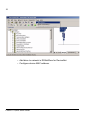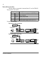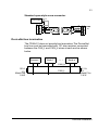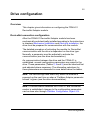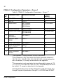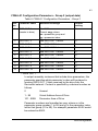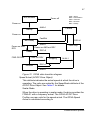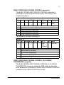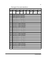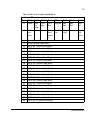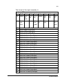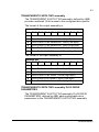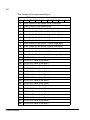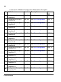
1
ABB Drives
User’s Manual
DeviceNet Adapter Module
FDNA-01
DeviceNet Adapter Module
FDNA-01
User’s Manual
3AFE68573360 Rev C
EN
EFFECTIVE: 09.10.2007
© 2007 ABB Oy. All Rights Reserved.
5
Safety instructions
Overview
This chapter states the general safety instructions that must be
followed when installing and operating the FDNA-01 DeviceNet
Adapter module.
The material in this chapter must be studied before attempting any
work on, or with, the unit.
In addition to the safety instructions given below, read the
complete safety instructions of the specific drive you are working
on.
General safety instructions
WARNING! All electrical installation and maintenance work on the
drive should be carried out by qualified electricians.
The drive and adjoining equipment must be properly earthed.
Do not attempt any work on a powered drive. After switching off
the mains, always allow the intermediate circuit capacitors 5
minutes to discharge before working on the frequency converter,
the motor or the motor cable. It is good practice to check (with a
voltage indicating instrument) that the drive is in fact discharged
before beginning work.
The motor cable terminals of the drive are at a dangerously high
voltage when mains power is applied, regardless of motor
operation.
There can be dangerous voltages inside the drive from external
control circuits even when the drive mains power is shut off.
Exercise appropriate care when working on the unit. Neglecting
these instructions can cause physical injury or death.
Safety instructions
6
Safety instructions
7
Table of contents
Safety instructions . . . . . . . . . . . . . . . . . . . . . . . . . . . . . . . . . . . . . . . . . . . . 5
Overview . . . . . . . . . . . . . . . . . . . . . . . . . . . . . . . . . . . . . . . . . . . . . . . . . . . . 5
General safety instructions . . . . . . . . . . . . . . . . . . . . . . . . . . . . . . . . . . . . . . . 5
Table of contents . . . . . . . . . . . . . . . . . . . . . . . . . . . . . . . . . . . . . . . . . . . . . 7
Introduction . . . . . . . . . . . . . . . . . . . . . . . . . . . . . . . . . . . . . . . . . . . . . . . . 11
Intended audience . . . . . . . . . . . . . . . . . . . . . . . . . . . . . . . . . . . . . . . . . . . .
Before you start . . . . . . . . . . . . . . . . . . . . . . . . . . . . . . . . . . . . . . . . . . . . . .
What this manual contains . . . . . . . . . . . . . . . . . . . . . . . . . . . . . . . . . . . . . .
Further Information . . . . . . . . . . . . . . . . . . . . . . . . . . . . . . . . . . . . . . . . . . . .
11
11
11
12
Overview . . . . . . . . . . . . . . . . . . . . . . . . . . . . . . . . . . . . . . . . . . . . . . . . . . . 13
Overview . . . . . . . . . . . . . . . . . . . . . . . . . . . . . . . . . . . . . . . . . . . . . . . . . . .
DeviceNet standard . . . . . . . . . . . . . . . . . . . . . . . . . . . . . . . . . . . . . . . . . . .
The FDNA-01 DeviceNet Adapter module . . . . . . . . . . . . . . . . . . . . . . . . . .
Compatibility . . . . . . . . . . . . . . . . . . . . . . . . . . . . . . . . . . . . . . . . . . . . . . .
Delivery check . . . . . . . . . . . . . . . . . . . . . . . . . . . . . . . . . . . . . . . . . . . . .
13
13
14
15
16
FDNA-01 Quick Start Guide . . . . . . . . . . . . . . . . . . . . . . . . . . . . . . . . . . . . 17
Overview . . . . . . . . . . . . . . . . . . . . . . . . . . . . . . . . . . . . . . . . . . . . . . . . . . .
PLC Configuration . . . . . . . . . . . . . . . . . . . . . . . . . . . . . . . . . . . . . . . . . . . .
Mechanical and electrical installation . . . . . . . . . . . . . . . . . . . . . . . . . . . . . .
Drive configuration . . . . . . . . . . . . . . . . . . . . . . . . . . . . . . . . . . . . . . . . . . . .
17
17
22
22
Mechanical installation . . . . . . . . . . . . . . . . . . . . . . . . . . . . . . . . . . . . . . . 29
Mounting . . . . . . . . . . . . . . . . . . . . . . . . . . . . . . . . . . . . . . . . . . . . . . . . . . . 29
Table of contents
8
Electrical installation . . . . . . . . . . . . . . . . . . . . . . . . . . . . . . . . . . . . . . . . . 31
Overview . . . . . . . . . . . . . . . . . . . . . . . . . . . . . . . . . . . . . . . . . . . . . . . . . . . .
General cabling instructions . . . . . . . . . . . . . . . . . . . . . . . . . . . . . . . . . . . . .
DeviceNet connection . . . . . . . . . . . . . . . . . . . . . . . . . . . . . . . . . . . . . . . . . .
DeviceNet bus termination . . . . . . . . . . . . . . . . . . . . . . . . . . . . . . . . . . . . . .
31
31
32
33
Drive configuration . . . . . . . . . . . . . . . . . . . . . . . . . . . . . . . . . . . . . . . . . . . 35
Overview . . . . . . . . . . . . . . . . . . . . . . . . . . . . . . . . . . . . . . . . . . . . . . . . . . . .
DeviceNet connection configuration . . . . . . . . . . . . . . . . . . . . . . . . . . . . . . .
FDNA-01 Configuration Parameters - Group 1 . . . . . . . . . . . . . . . . . . . . . . .
FDNA-01 Configuration Parameters - Group 2 (output data) . . . . . . . . . . . .
FDNA-01 Configuration Parameters - Group 3 (Input data) . . . . . . . . . . . . .
Control locations . . . . . . . . . . . . . . . . . . . . . . . . . . . . . . . . . . . . . . . . . . . . . .
35
35
36
43
44
45
Master configuration . . . . . . . . . . . . . . . . . . . . . . . . . . . . . . . . . . . . . . . . . 47
Overview . . . . . . . . . . . . . . . . . . . . . . . . . . . . . . . . . . . . . . . . . . . . . . . . . . . . 47
Configuring the system . . . . . . . . . . . . . . . . . . . . . . . . . . . . . . . . . . . . . . . . . 47
EDS files . . . . . . . . . . . . . . . . . . . . . . . . . . . . . . . . . . . . . . . . . . . . . . . . . . . . 47
Communication profiles . . . . . . . . . . . . . . . . . . . . . . . . . . . . . . . . . . . . . . . 49
Overview . . . . . . . . . . . . . . . . . . . . . . . . . . . . . . . . . . . . . . . . . . . . . . . . . . . .
Communication profiles . . . . . . . . . . . . . . . . . . . . . . . . . . . . . . . . . . . . . . . .
The ODVA AC/DC Drive Profiles . . . . . . . . . . . . . . . . . . . . . . . . . . . . . . . . .
ODVA Output Attributes . . . . . . . . . . . . . . . . . . . . . . . . . . . . . . . . . . . . . .
ODVA Input Attributes . . . . . . . . . . . . . . . . . . . . . . . . . . . . . . . . . . . . . . . .
The ABB Drives communication profile . . . . . . . . . . . . . . . . . . . . . . . . . . . .
The Control Word and the Status Word . . . . . . . . . . . . . . . . . . . . . . . . . .
References . . . . . . . . . . . . . . . . . . . . . . . . . . . . . . . . . . . . . . . . . . . . . . . .
Actual values . . . . . . . . . . . . . . . . . . . . . . . . . . . . . . . . . . . . . . . . . . . . . . .
49
49
51
52
55
59
59
60
62
Communication . . . . . . . . . . . . . . . . . . . . . . . . . . . . . . . . . . . . . . . . . . . . . . 69
Overview . . . . . . . . . . . . . . . . . . . . . . . . . . . . . . . . . . . . . . . . . . . . . . . . . . . . 69
Introduction to DeviceNet . . . . . . . . . . . . . . . . . . . . . . . . . . . . . . . . . . . . . . . 69
Object modelling and functional profiles . . . . . . . . . . . . . . . . . . . . . . . . . . . . 69
Table of contents
9
Assembly objects . . . . . . . . . . . . . . . . . . . . . . . . . . . . . . . . . . . . . . . . . . . . . 70
BASIC SPEED CONTROL assembly . . . . . . . . . . . . . . . . . . . . . . . . . . . . 71
BASIC SPEED CONTROL PLUS DRIVE PARAMETERS assembly . . . . 71
EXTENDED SPEED CONTROL assembly . . . . . . . . . . . . . . . . . . . . . . . 74
EXTENDED SPEED CONTROL PLUS DRIVE PARAMETERS
assembly . . . . . . . . . . . . . . . . . . . . . . . . . . . . . . . . . . . . . . . . . . . . . . . . . 74
BASIC SPEED AND TORQUE CONTROL assembly . . . . . . . . . . . . . . . 77
BASIC SPEED AND TORQUE CONTROL PLUS DRIVE PARAMETERS
assembly . . . . . . . . . . . . . . . . . . . . . . . . . . . . . . . . . . . . . . . . . . . . . . . . . 77
EXTENDED SPEED AND TORQUE CONTROL assembly . . . . . . . . . . . 80
EXTENDED SPEED AND TORQUE CONTROL PLUS DRIVE
PARAMETERS assembly . . . . . . . . . . . . . . . . . . . . . . . . . . . . . . . . . . . . . 80
ABB DRIVES PROFILE SET SPEED assembly . . . . . . . . . . . . . . . . . . . 83
ABB DRIVES PROFILE WITH SET SPEED PLUS DRIVE PARAMETERS
assembly . . . . . . . . . . . . . . . . . . . . . . . . . . . . . . . . . . . . . . . . . . . . . . . . . 83
ABB DRIVES PROFILE WITH SET SPEED AND SET TORQUE
assembly . . . . . . . . . . . . . . . . . . . . . . . . . . . . . . . . . . . . . . . . . . . . . . . . . 86
ABB DRIVES PROFILE WITH SET SPEED AND SET TORQUE PLUS
DRIVE PARAMETERS assembly . . . . . . . . . . . . . . . . . . . . . . . . . . . . . . . 87
TRANSPARENT16 WITH ONE assembly . . . . . . . . . . . . . . . . . . . . . . . . 90
TRANSPARENT16 WITH ONE assembly PLUS DRIVE PARAMETERS 91
TRANSPARENT16 WITH TWO assembly . . . . . . . . . . . . . . . . . . . . . . . . 93
TRANSPARENT16 WITH TWO assembly PLUS DRIVE PARAMETERS 93
TRANSPARENT32 WITH ONE assembly . . . . . . . . . . . . . . . . . . . . . . . . 96
TRANSPARENT32 WITH ONE assembly PLUS DRIVE PARAMETERS 96
TRANSPARENT32 WITH TWO assembly . . . . . . . . . . . . . . . . . . . . . . . . 99
TRANSPARENT32 WITH TWO assembly PLUS DRIVE
PARAMETERS . . . . . . . . . . . . . . . . . . . . . . . . . . . . . . . . . . . . . . . . . . . . 100
Class objects . . . . . . . . . . . . . . . . . . . . . . . . . . . . . . . . . . . . . . . . . . . . . . . 104
Identity Object, Class 01h . . . . . . . . . . . . . . . . . . . . . . . . . . . . . . . . . . . . 104
DeviceNet Object, Class 03h . . . . . . . . . . . . . . . . . . . . . . . . . . . . . . . . . 108
Connection Object, Class 05h . . . . . . . . . . . . . . . . . . . . . . . . . . . . . . . . 110
Acknowledge Handler Object, Class 2Bh . . . . . . . . . . . . . . . . . . . . . . . . 112
Motor Data Object, Class 28h . . . . . . . . . . . . . . . . . . . . . . . . . . . . . . . . 113
Control Supervisor Object, Class 29h . . . . . . . . . . . . . . . . . . . . . . . . . . 115
AC/DC-Drive Object, Class 2Ah . . . . . . . . . . . . . . . . . . . . . . . . . . . . . . . 117
Drive Parameter Object, Class 90h . . . . . . . . . . . . . . . . . . . . . . . . . . . . 118
Fieldbus Configuration Object 91h . . . . . . . . . . . . . . . . . . . . . . . . . . . . . 119
Table of contents
10
Diagnostics . . . . . . . . . . . . . . . . . . . . . . . . . . . . . . . . . . . . . . . . . . . . . . . . 125
LED indications . . . . . . . . . . . . . . . . . . . . . . . . . . . . . . . . . . . . . . . . . . . . . . 125
Definitions and abbreviations . . . . . . . . . . . . . . . . . . . . . . . . . . . . . . . . . 129
Technical data . . . . . . . . . . . . . . . . . . . . . . . . . . . . . . . . . . . . . . . . . . . . . . 133
FDNA-01 . . . . . . . . . . . . . . . . . . . . . . . . . . . . . . . . . . . . . . . . . . . . . . . . . . . 133
Fieldbus link . . . . . . . . . . . . . . . . . . . . . . . . . . . . . . . . . . . . . . . . . . . . . . . . 134
Appendix - Varying Number of Drive Parameters . . . . . . . . . . . . . . . . . 135
Table of contents
11
Introduction
Intended audience
The manual is intended for people responsible for installing,
commissioning and using an FDNA-01 DeviceNet Adapter
module. The reader is expected to have a basic knowledge of
electrical fundamentals, electrical wiring practices and how to
operate the drive.
Before you start
It is assumed that the drive is installed and ready to operate before
starting the installation of the extension module.
In addition to conventional installation tools, have the drive
manuals available during the installation as they contain important
information not included in this manual. The drive manuals are
referred to at various points of this document.
What this manual contains
This manual contains information on the wiring, configuration and
use of the FDNA-01 DeviceNet Adapter module.
Safety instructions are featured in the first few pages of this
manual.
Overview contains short descriptions of the DeviceNet protocol
and the FDNA-01 DeviceNet Adapter module, and a delivery
checklist.
Quick start-up guide contains a short description of how to set
up the FDNA-01 DeviceNet Adapter module using the ACS350
drive as an example.
Mechanical installation contains placing and mounting
instructions for the module.
Electrical installation contains wiring, bus termination and
earthing instructions.
Introduction
12
Drive configuration explains how to program the drive before the
communication through the adapter module can be started.
Master configuration explains how to program the DeviceNet
master before communication through the adapter module can be
started.
Communication profiles describes the communication profiles
used in the communication between the DeviceNet network, the
FDNA-01 module and the drive.
Communication contains a description of the DeviceNet
functionality supported by the FDNA-01.
Diagnostics explains how to trace faults with the status LEDs on
the FDNA-01 module.
Definitions and abbreviations explains definitions and
abbreviations concerning the DeviceNet protocol family.
Technical data contains information on physical dimensions,
configurable settings and connectors of the module and a
specification of the DeviceNet link.
Further Information
Further information on the DeviceNet protocol is available on the
world wide web from www.odva.org.
Introduction
13
Overview
Overview
This chapter contains a short description of the DeviceNet
standard and the FDNA-01 Adapter module, and a delivery
checklist.
DeviceNet standard
The DeviceNet network has a linear bus topology. Terminating
resistors are required on each end of the trunk line. Drop lines as
long as 6 metres (20 feet) each are permitted, allowing one or
more nodes to be attached. DeviceNet allows branching
structures only on drop lines. An example of an allowable topology
is shown in Figure 1.
Trunk line
Tap
Node
Node
Node
Tap
Node
Node
Node
Terminating
Resistor
Tap
Node
Node
Tap
Node
Drop line
Node
Node
Figure 1. DeviceNet bus topology
The maximum length of trunk cable depends on the data rate and
on the type of the cable used (see chapter Technical data).
Overview
14
Terminating resistor
The DeviceNet network should be terminated at both ends of the
trunk cable with a 121 Ω, ¼ W, 1% Metal Film resistor. Connect
this resistor between the two signal wires (CAN_H, CAN_L) on the
DeviceNet cable.
The FDNA-01 DeviceNet Adapter module
The FDNA-01 DeviceNet Adapter module is an optional device for
ABB drives which enables the connection of the drive to a
DeviceNet network. The drive is considered as a slave in the
DeviceNet network. Through the FDNA-01 DeviceNet Adapter
module it is possible to:
• give control commands to the drive
(Start, Stop, Run enable, etc.)
• feed a motor speed or torque reference to the drive
• give a process actual value or a process reference to the PID
controller of the drive
• read status information and actual values from the drive
• change drive parameter values
• reset a drive fault.
The FDNA-01 acts as a Class 2 slave only with predefined
master-slave connection set services. These include the Explicit
Messaging, the Poll-Response service and the Change of State/
Cyclic service. The DeviceNet commands and services supported
by the FDNA-01 DeviceNet Adapter module are discussed in
chapter Communication.
The adapter module is mounted into an option slot on the motor
control board of the drive. See the drive documentation for module
placement options.
Overview
15
DeviceNet
master
ABB drive
Other slave
device
Diagnostic LEDs
(See chapter Diagnostics)
Bus connector X1
(see chapter Electrical
installation)
Figure 2. The construction of the DeviceNet link and the
FDNA-01 Adapter module.
Compatibility
The FDNA-01 is compatible with all master stations that support
the DeviceNet protocol.
Overview
16
Delivery check
The option package for the FDNA-01 DeviceNet Adapter module
contains:
• DeviceNet Adapter module, type FDNA-01
• this manual.
Overview
17
FDNA-01 Quick Start Guide
Overview
This document presents the steps to take during the start-up of the
FDNA-01 DeviceNet Adapter Module.
PLC Configuration
This is an example on how to set up an Allen-Bradley
CompactLogix PLC with a 1769-SDN DeviceNet Scanner to use
an ACS350 or ACSM1 equipped with a FDNA-01 fieldbus adapter,
using RSNetWorx and RSLogix 5000 to configure and control the
network. Slight vendor specific differences may exist when using
other programs or master devices.
• Select and import the EDS file for drive, for example
ACS350_FDNA01_v1.27_eu.EDS. For more help on choosing
the correct file, refer to ABB EDS Selection Guide document
delivered with the EDS files.
Note: Only one EDS file with the same Product ID can be installed
in the PLC at a time.
FDNA-01 Quick Start Guide
18
• Add drive to network in RSNetWorx for DeviceNet.
• Configure device MAC address.
FDNA-01 Quick Start Guide
19
FDNA-01 Quick Start Guide
20
• Configure the DeviceNet Scanner. Add the drive to Scanlist and
edit I/O parameters. Select Polled or Change of State/Cyclic.
Then enter the input and output sizes of the I/O assemblies that
will be used (e.g. for Basic Speed Control Assemblies 20 and
70, each size is set to 4 bytes.).
• For convenience, you can also edit the Input and Output
memory mappings. By default, the two 16-bit input words are
mapped into a single 32-bit double word. It is more convenient,
however, to map them into separate double words. Output
words can be mapped similarly.
FDNA-01 Quick Start Guide
21
• Download the scanner settings to the device in online mode.
• Add your DeviceNet scanner to an RSLogix 5000 project. You
should get new Controller Tags Local:<slot>:I and
Local:<slot>:O. You can use them to access the data as
mapped above:
Local:<slot>:O.Data[0] is the Control Word
Local:<slot>:O.Data[1] is the Reference
Local:<slot>:I.Data[0] is the Status Word
Local:<slot>:I.Data[1] is the Actual Value
Note: You may need to change the value of
Local:<slot>:O.CommandRegister.Run or
FDNA-01 Quick Start Guide
22
Local:<slot>:I.CommandRegister.Run to 1.
Mechanical and electrical installation
• Insert the FDNA-01 into its specified slot in the drive
• Fasten the screw
• Plug the fieldbus connector into the module
Note: It is recommended to set module communication settings
(e.g. Baud rate) before connecting it to an active DeviceNet
network (see below).
Drive configuration
Note: Configuring the drive for communication with the module is
dependent on the drive type. Refer to the Firmware Manual of the
drive for detailed information on configuring the drive to use the
communication module.
• Power up the drive.
• Configure drive to enable module. With an ACS350 drive, set
parameter 98.02 COMM PROT SEL to EXT FBA. With ACSM1,
set parameter 50.01 FBA ENABLE to Enable and ensure that
50.04 FBA REF1 MODESEL is Speed and 50.05 FBA REF2
MODESEL is Torque.
• Verify that FBA TYPE is DEVICENET. On the ACS350 and
ACSM1 drives, this is parameter 51.01.
• Configure drive to accept Start/Stop, Direction, Reference, Run
Enable and Fault Reset from the module. Examples of
appropriate values are shown in the following tables.
• Configure the module for desired network characteristics with
the fieldbus configuration groups. Examples of suggested
values are shown in the following tables.
• Initiate a "Fieldbus adapter parameter refresh" by setting
parameter 51.27 FBA PAR REFRESH.
FDNA-01 Quick Start Guide
23
Note: The new settings take effect only when the module is
powered up the next time or when a 'Fieldbus Adapter parameter
refresh' is given (see the drive documentation).
Example Configuration: ODVA Basic Speed Control on ACS350
Drive parameter
Example setting for ACS350
10.01 EXT1 COMMANDS
COMM
11.03 REF1 SELECT
COMM
16.01 RUN ENABLE
NOT SEL1
16.04 FAULT RESET SEL
COMM
98.02 COMM PROT SEL
EXT FBA
51.01 FBA TYPE
51.02 MAC ID
51.03 BAUD RATE
DEVICENET
2
0 (125 kbit/s)
51.05 ODVA STOP FUNC
0 (Ramp Stop)
51.06 OUTPUT INSTANCE
20 (ODVA Basic Speed Control)
51.07 OUTPUT NUM PARS
10 2
51.08 INPUT INSTANCE
70 (ODVA Basic Speed Control)
51.09 INPUT NUM PARS
10 2
51.10 ODVA SPEED SCALE
51.11 ODVA TORQUE SCALE
128 (1 RPM)
128 (1 Nm)
1
The ODVA AC/DC Drive Profile does not provide a means to
supply a RUN ENABLE signal via DeviceNet. The RUN ENABLE
for the drive must either be set to either NOT SEL or another
source (e.g. a digital input).
2
OUTPUT NUM PARS and INPUT NUM PARS should always be
set to 10, except as provided for in the Appendix.
Scanner: Input and Output sizes are 4 bytes each.
FDNA-01 Quick Start Guide
24
Example Configuration: ABB Drives Profile w/ Speed and Torque
plus Drive Parameters on ACS350. Output Drive Parameters will
control Analog Output 1 and Relay Output 1. Input Drive
Parameters will read Analog Input 1 (01.20), Current (01.04) and
Power (01.06).
Drive parameter
Example setting for ACS350
10.01 EXT1 COMMANDS
COMM
11.03 REF1 SELECT
COMM
11.05 REF2 SELECT
COMM
14.01 RELAY OUTPUT 1
COMM
15.01 AO1 CONTENT SEL
COMM VALUE 1
16.01 RUN ENABLE
COMM1
16.04 FAULT RESET SEL
COMM
98.02 COMM PROT SEL
COMM
51.01 FBA TYPE
51.02 MAC ID
51.03 BAUD RATE
DEVICENET
53
2 (500kbit/s)
51.05 ODVA STOP FUNC
0 (= Ramp Stop) 2
51.06 OUTPUT INSTANCE
902 (ABB Drives Profile w/ Speed
and Torque plus Drive Parameters)
51.07 OUTPUT NUM PARS
10 3
51.08 INPUT INSTANCE
952 (ABB Drives Profile w/ Speed
and Torque plus Drive Parameters)
51.09 INPUT NUM PARS
10 3
51.10 ODVA SPEED SCALE
51.11 ODVA TORQUE SCALE
128 (1 RPM) 2
128 (1 Nm) 2
54.01 FBA DATA IN 1
120 (01.20 Analog Input 1)
54.02 FBA DATA IN 2
104 (01.04 Current)
54.03 FBA DATA IN 3
106 (01.06. Power)
54.04 - 54.10 FBA DATA IN 4-10
FDNA-01 Quick Start Guide
0 (Unused)
25
55.01 FBA DATA OUT 1
135 (01.35 COMM VALUE 1)
55.02 FBA DATA OUT 2
134 (01.34 COMM RO WORD)
55.03 - 55.10 FBA DATA OUT 3-10
0 (Unused)
1
The ABB Drives Profile does provide a means to supply a RUN
ENABLE signal via DeviceNet. The RUN ENABLE for the drive
may be set to COMM or another source (e.g. a digital input).
2
These parameters are ignored when using ABB Drives profile.
3
OUTPUT NUM PARS and INPUT NUM PARS should always be
set to 10, except as provided for in the Appendix.
Scanner: Input and Output sizes are 26 bytes each.
Example Configuration: ODVA Extended Speed and Torque
Control on ACSM1
Drive parameter
10.01 EXT1 START FUNC
Example setting for ACSM1
FBA
24.01 SPEED REF1 SEL
FBA REF1
32.01 TORQ REF1 SEL
FBA REF2
34.03 EXT1 CTRL MODE1
SPEED
34.04 EXT1 CTRL MODE2
TORQUE
50.01 FBA ENABLE
ENABLE
50.04 FBA REF1 MODESEL
SPEED
50.05 FBA REF2 MODESEL
TORQUE
51.01 FBA TYPE
51.02 MAC ID
51.03 BAUD RATE
DEVICENET
10
0 (125 kbit/s)
51.05 ODVA STOP FUNC
0 (=Ramp Stop)
51.06 OUTPUT INSTANCE
23 (ODVA Extended Speed and
Torque Control)
51.07 OUTPUT NUM PARS
101
FDNA-01 Quick Start Guide
26
51.08 INPUT INSTANCE
73 (ODVA Extended Speed and
Torque Control)
51.09 INPUT NUM PARS
101
51.10 ODVA SPEED SCALE
128 (1 RPM)
51.11 ODVA TORQUE SCALE
1
128 (1 Nm)
OUTPUT NUM PARS and INPUT NUM PARS should always be
set to 10, except as provided for in the Appendix
Scanner: Input and Output sizes are 6 bytes each
Example configuration: ABB Drives profile with Speed control with
ACSM1
Drive parameter
10.01 EXT1 START FUNC
24.01 SPEED REF1
Example setting for ACSM1
FBA
FBA REF1
34.03 EXT1 CTRL MODE1
SPEED
50.01 FBA ENABLE
ENABLE
50.04 FBA REF1 MODESEL
SPEED
50.05 FBA REF2 MODESEL
TORQUE
51.01 FBA TYPE
51.02 MAC ID
51.03 BAUD RATE
DEVICENET
10
1 (250 kbit/s)
51.05 ODVA STOP FUNC
0 (= Ramp Stop)
51.06 OUTPUT INSTANCE
801 (ABB Drives with Set speed)
51.07 OUTPUT NUM PARS
102
51.08 INPUT INSTANCE
851 (ABB Drives with Set speed)
51.09 INPUT NUM PARS
102
51.10 ODVA SPEED SCALE
51.11 ODVA TORQUE SCALE
1
128 (1 RPM)
128 (1 Nm)
These parameters are ignored when using ABB Drives profile.
FDNA-01 Quick Start Guide
27
2
OUTPUT NUM PARS and INPUT NUM PARS should always be set to 10,
except as provided for in the Appendix.
FDNA-01 Quick Start Guide
28
FDNA-01 Quick Start Guide
29
Mechanical installation
WARNING! Follow the safety instructions given in this manual and
the drive documentation.
Mounting
The FDNA-01 is to be inserted into its specific position in the drive.
The module is held in place with plastic pins and one screw. The
screw also provides the earthing of the fieldbus cable shield
connected to the module.
On installation of the module, the signal and power connection to
the drive is made through a 20-pin connector. (All drives do not
use all the available signals so the connector on the drive may
have fewer pins.)
Mounting procedure:
• Insert the module carefully into its position on the drive.
• Fasten the screw.
Note: Correct installation of the screw is essential for fulfilling the
EMC requirements and for proper operation of the module.
Mechanical installation
30
Mechanical installation
31
Electrical installation
Overview
This chapter contains:
• general cabling instructions
• instructions for connecting the module to the DeviceNet bus.
WARNING! Before installation, switch off the drive power supply.
Wait 5 minutes to ensure that the capacitor bank of the drive is
discharged. Switch off all dangerous voltages connected from
external control circuits to the inputs and outputs of the drive.
General cabling instructions
Arrange the bus cables as far away from the motor cables as
possible. Avoid parallel runs. Use bushings at cable entries.
Electrical installation
32
DeviceNet connection
The bus cable is connected to terminal block X1 on the FDNA-01.
Terminal block description.
X1
Description
1
V-
Network power supply ground (0V DC)
2
CAN_L CAN_L bus line
3
SHLD Network cable shield
4
CAN_H CAN_H bus line
5
V+
Network power supply source (24V DC)
Connection examples
5-pin micro-style connector
0V
Network
power supply +24 V
VCAN_L
SHLD
CAN_H
V+
1 2 3 4 5
VCAN_L
SHLD
CAN_H
V+
1 2 3 4 5
Male micro-style
2
connector
1
3
4
5
4
5
3
2
1
FDNA
X1
5-pin mini-style connector
0V
Network
power supply +24 V
Male mini-style
connector
2
1
3
4
2
5
4
5
1
3
Electrical installation
FDNA
X1
33
Standard open-style screw connector
+24 V
Network
power supply 0 V
1 2 3 4 5
1 2 3 4 5
VCAN_L
SHLD
CAN_H
V+
FDNA
X1
DeviceNet bus termination
The FDNA-01 does not provide bus termination.The DeviceNet
bus line must be terminated with 121 ohm resistors connected
between the CAN_L and CAN_H wires at each end as shown
below.
Scanner
Node 1
• • •
Node n
CAN_H
121 Ω
1%
Metal Film
1/4 W
CAN_L
121 Ω
1%
Metal Film
1/4 W
Electrical installation
34
Electrical installation
35
Drive configuration
Overview
This chapter gives information on configuring the FDNA-01
DeviceNet Adapter module.
DeviceNet connection configuration
After the FDNA-01 DeviceNet Adapter module has been
mechanically and electrically installed according to the instructions
in chapters Mechanical installation and Electrical installation, the
drive must be prepared for communication with the module.
The detailed procedure of activating the module for DeviceNet
communication with the drive is dependent on the drive type.
Normally, a parameter must be adjusted to activate the
communication (see the drive documentation).
As communication between the drive and the FDNA-01 is
established, several configuration parameters are copied to the
drive. These parameters (Tables 3, 8 and 9) must be checked first
and adjusted where necessary. The alternative selections for
these parameters are discussed in more detail below the tables.
Note: The new settings take effect only when the module is
powered up the next time or when a ‘Fieldbus Adapter parameter
refresh’ is given (see the drive documentation).
Note: If communication between the FDNA-01 and DeviceNet
master is established, changes to the configuration parameters
can be done also through Fieldbus Configuration Object 91h.
Drive configuration
36
FDNA-01 Configuration Parameters - Group 1
Table 3. FDNA-01 Configuration Parameters - Group 1 *
Par.
no.
Parameter name
Alternative settings
Default
setting
1
FBA TYPE
(Read-only)
DEVICENET
2
MAC ID
0 to 63
63
3
BAUD RATE
(0) 125 kbit/s;
(1) 250 kbit/s;
(2) 500 kbit/s
(0) 125 kbit/s
4
DRIVE PROFILE
(0) DCU Profile
(0) DCU Profile
5
ODVA STOP FUNC (0) Ramp Stop;
(1) Coast Stop
(0) Ramp Stop
6
OUTPUT
INSTANCE
See Table 4.
20
7
OUTPUT NUM
PARS
1 to 10 1,2
10
8
INPUT INSTANCE
See Table 4.
70
9
INPUT NUM PARS
1 to 10 1,3
10
10
ODVA SPEED
SCALE
See Table 6.
128
11
ODVA TORQUE
SCALE
See Table 7.
128
1See
Appendix - Varying Number of Drive Parameters
2
This parameter is only used when the Output Assembly Instance is
120, 121, 122, 123, 901, 902, 911, 912, 921, 922. It should always be
set to the default, 10, except as described in the Appendix.
3This
parameter is only used when the Input Assembly Instance is 170,
171, 172, 173, 951, 952, 961, 962, 971, 972. It should always be set to
the default, 10, except as described in the Appendix.
*Actual parameter group number depends on the drive type. E.g.
Group#1 equals to parameter Group 51 in ACS350 and ACSM1.
Drive configuration
37
1 FBA TYPE
This parameter shows the fieldbus adapter type as detected by
the drive. The value cannot be adjusted by the user.
If this parameter is undefined, the communication between the
drive and the module has not been established.
2 MAC ID
Each device on the DeviceNet network must have a unique MAC
ID number. This parameter is used to define the MAC ID number
for the drive it is connected to.
3 BAUD RATE
Sets the baud rate for the DeviceNet interface. This is user
selectable, but must be the same on every node on the DeviceNet
network.
4 DRIVE PROFILE
The “drive profile” defines the communication used between the
module and the drive (not fieldbus and module). If a drive supports
more than one drive profile, this parameter is used to select the
preferred profile. Presently to use the ODVA and ABB Drives
profiles the drive must support the DCU profile. Transparent16
and Transparent32 profiles may be used with any drive profile.
5 ODVA STOP FUNC
This parameter only applies when using the ODVA AC/DC Drive
Profile. It determines how the motor will be stopped when a stop
command is received via DeviceNet
0 = Ramp stop: the motor decelerates along the active
deceleration ramp.
1 = Coast stop: the motor comes to a stop by coasting.
6 OUTPUT INSTANCE
8 INPUT INSTANCE
These parameters configure the output and input assembly
instances used by the DeviceNet Adapter Module. The following
tables list supported assemblies and allowed combinations. For
Drive configuration
38
descriptions of assembly instances, see Communication Assembly Objects.
Drive configuration
39
Table 4. Assembly Instances
Output
Instance
Input
Instance
Default Input
Size (bytes)
Profile
Basic Speed Control
20
70
4
ODVA AC/DC Drive
Enhanced Speed Control
21
71
4
ODVA AC/DC Drive
Basic Speed and Torque
Control
22
72
6
ODVA AC/DC Drive
Enhanced Speed and
Torque Control
23
73
6
ODVA AC/DC Drive
Basic Speed Control plus
Drive Parameters
120
170
24
ODVA AC/DC Drive
Enhanced Speed Control
plus Drive Parameters
121
171
24
ODVA AC/DC Drive
Basic Speed and Torque
Control plus Drive
Parameters
122
172
26
ODVA AC/DC Drive
Enhanced Speed and
Torque Control
plus Drive Parameters
123
173
26
ODVA AC/DC Drive
ABB Drives Profile w/ Set
Speed
801
851
4
ABB Drives Profile
ABB Drives Profile w/
Set Speed and Set Torque
802
852
6
ABB Drives Profile
ABB Drives Profile w/
Set Speed plus Drive
Parameters
901
951
24
ABB Drives Profile
ABB Drives Profile w/
Set Speed and Set Torque
plus Drive Parameters
902
952
26
ABB Drives Profile
Transparent16 w/One
811
861
4
Transparent16 Profile
Transparent16 w/Two
812
862
6
Transparent16 Profile
Transparent16 w/One plus
Drive Parameters
911
961
24
Transparent16 Profile
Transparent16 w/Two plus
Drive Parameters
912
962
26
Transparent16 Profile
Transparent32 w/One
821
871
8
Transparent32 Profile
Name
Drive configuration
40
Output
Instance
Input
Instance
Default Input
Size (bytes)
Profile
Transparent32 w/Two
822
872
12
Transparent32 Profile
Transparent32 w/One plus
Drive Parameters
921
971
28
Transparent32 Profile
Transparent32 w/Two plus
Drive Parameters
922
972
32
Transparent32 Profile
Name
Note: With ACSM1, when using ODVA AC/DC Drive or ABB
Drives profile, make sure that the drive parameter 50.4 FBA REF
MODESEL is set to SPEED and 50.5 FBA REF2 MODESEL is set
to TORQUE.
Table 5. Allowed Output/Input Assembly Instance Combinations
Output/Input
ODVA
ABB DRIVES
TRANSPARENT16
(70-73; 170-173) (851-852; 951-952) (861-862; 961-962)
ODVA
(20-23; 120-123)
TRANSPARENT32
(871-872; 971-972)
X
ABB DRIVES
(801-802; 901-902)
TRANSPARENT16
(811-812; 911-912)
TRANSPARENT32
(821-822; 921-922)
X
X
X
7 OUTPUT NUM PARS
9 INPUT NUM PARS
Some assembly instances support transferring drive parameter
values between the I/O scanner and drive. These parameters
specify how many drive parameter values should be included in
the respective assembly instance. Changing the numbers of drive
parameters to values other than the defaults also changes the
lengths of the associated assembly instances. This requires
manual changes to either the EDS file or I/O scanner
configuration. Please consult the Appendix - Varying Number of
Drive Parameters before changing these parameters.
Drive configuration
41
10 ODVA SPEED SCALE
This parameter only applies when using the ODVA AC/DC Drive
Profile. Units of reference and actual speeds for ODVA AC/DC
Drive profiles are given by the formula below. This parameter does
not affect ABB Drives profiles. Note that while a wide range of
resolutions may be configured, actual performance will be limited
to the performance capabilities of the drive.
Speed Unit = RPM X 2(-1 X ODVA Speed Scale Value)
Table 6. ODVA Speed Scaling
ODVA
Speed Scale
Value1
Drive Parameter
Speed Scale Value2
Unit
-5
123
32 RPM
-4
124
16 RPM
-3
125
8 RPM
-2
126
4 RPM
-1
127
2 RPM
0 (default)
128
1 RPM
1
129
0.5 RPM
2
130
0.25 RPM
3
131
0.125 RPM
4
132
0.0625 RPM
5
133
0.03125 RPM
1
Use “ODVA Speed Scale Value” when reading/writing ODVA
Speed Scale via the AC/DC Drive Object (2Ah). When written via
AC/DC Drive Object, the new value takes effect immediately.
2
Use “Drive Parameter Speed Scale Value” when reading/writing
ODVA Speed Scale via Drive Panel, Drive Parameter Object (90h)
and Drive Configuration Object (91h). When written via these
methods, the new value takes effect after the drive is repowered or
a “Fieldbus Adapter Parameter refresh” is given.
Drive configuration
42
11 ODVA TORQUE SCALE
This parameter only applies when using the ODVA AC/DC Drive
Profile. Units of reference and actual torques for ODVA AC/DC
Drive profiles are given by the formula below. This parameter does
not affect ABB Drives profiles. Note that while a wide range of
resolutions may be configured, actual performance will be limited
to the performance capabilities of the drive. (Nm = Newton x
Meter)
Torque Unit = Nm x 2(-1 X ODVA Torque Scale)
Table 7. ODVA Torque Scaling
ODVA
Torque Scale
Value1
Drive Parameter Unit
Torque Scale
Value2
-5
123
32 Nm
-4
124
16 Nm
-3
125
8 Nm
-2
126
4 Nm
-1
127
2 Nm
0 (default)
128
1 Nm
1
129
0.5 Nm
2
130
0.25 Nm
3
131
0.125 Nm
4
132
0.0625 Nm
5
133
0.03125 Nm
1Use
“ODVA Torque Scale Value” when reading/writing ODVA
Torque Scale via the AC/DC Drive Object (2Ah). When written via
AC/DC Drive Object, the new value takes effect immediately.
2
Use “Drive Parameter Torque Scale Value” when reading/writing
ODVA Torque Scale via Drive Panel, Drive Parameter Object
(90h) and Drive Configuration Object (91h). When written via
these methods, the new value takes effect after the drive is
repowered or a “Fieldbus Adapter Parameter refresh” is given.
Drive configuration
43
FDNA-01 Configuration Parameters - Group 2 (output data)
Table 8. FDNA-01 Configuration Parameters - Group 2
Par.
no.
Parameter name
Alternative settings
Default
setting
1
DATA OUT 1
(master to drive)
0 to 9999
Format: xxyy, where
xx = parameter group and
yy = parameter index.
0
2
DATA OUT 2
See DATA OUT 1 above.
0
3
DATA OUT 3
See DATA OUT 1 above.
0
4
DATA OUT 4
See DATA OUT 1 above.
0
5
DATA OUT 5
See DATA OUT 1 above.
0
6
DATA OUT 6
See DATA OUT 1 above.
0
7
DATA OUT 7
See DATA OUT 1 above.
0
8
DATA OUT 8
See DATA OUT 1 above.
0
9
DATA OUT 9
See DATA OUT 1 above.
0
10
DATA OUT 10
See DATA OUT 1 above.
0
1 DATA OUT 1
In output assembly instances that include drive parameters, this
parameter specifies which parameter’s value will be placed in
location DATA OUT 1 Value received by the drive from the
DeviceNet network. Content is specified by a decimal number as
follows.
0
Unused
1 - 99
Virtual Address Area of Drive
101 - 9999
Parameter Area of Drive
Parameter numbers are formatted as xxyy, where xx is the
parameter group number (1 to 99) and yy is the parameter index
within that group (01 to 99). For example, parameter 99.02 would
be entered as 9902.
Drive configuration
44
*Actual parameter group number depends on the drive type. E.g.
Group#2 equals to parameter Group 55 in ACS350 or group 53 in
ACSM1.
2-10 DATA OUT 2 to DATA OUT 10
See DATA OUT 1 above.
FDNA-01 Configuration Parameters - Group 3 (Input data)
Table 9. FDNA-01 Configuration Parameters - Group 3*
Par.
no.
Parameter name
Alternative settings
Default
setting
1
DATA IN 1
(drive to master)
0 to 9999
Format: xxyy, where
xx = parameter group and
yy = parameter index.
0
2
DATA IN 2
See DATA IN 1 above.
0
3
DATA IN 3
See DATA IN 1 above.
0
4
DATA IN 4
See DATA IN 1 above.
0
5
DATA IN 5
See DATA IN 1 above.
0
6
DATA IN 6
See DATA IN 1 above.
0
7
DATA IN 7
See DATA IN 1 above.
0
8
DATA IN 8
See DATA IN 1 above.
0
9
DATA IN 9
See DATA IN 1 above.
0
10
DATA IN 10
See DATA IN 1 above.
0
1 DATA IN 1
In input assembly instances that include drive parameters, this
parameter specifies which parameter’s value will be placed in
location DATA IN 1 Value sent by the drive to the DeviceNet
network. Content is specified by a decimal number as follows.
Unused
1 - 99
Virtual Address Area of Drive
101 - 9999
Parameter Area of Drive
Drive configuration
45
Parameter numbers are formatted as xxyy, where xx is the
parameter group number (1 to 99) and yy is the parameter index
within that group (01 to 99). For example, parameter 99.02 would
be entered as 9902.
*Actual parameter group number depends on the drive type. E.g.
Group#3 equals to parameter Group 54 in ACS350 or group 52 in
ACSM1.
2-10 DATA IN 2 to DATA IN 10
See DATA IN 1 above.
NOTE: The FDNA-01 configuration parameters are 16-bit
parameters. If the mapped parameter is a 32-bit parameter, it
automatically reserves two consecutive parameters. E.g.,
mapping of a 32-bit parameter to parameter no. 1 reserves also
parameter no. 2.
Control locations
ABB drives can receive control information from multiple sources
including digital inputs, analogue inputs, the drive control panel
and a communication module (e.g. FDNA-01). ABB drives allow
the user to separately determine the source for each type of
control information (Start, Stop, Direction, Reference, Fault Reset,
etc.). In order to give the fieldbus master station the most
complete control over the drive, the communication module must
be selected as source for this information. See the user
documentation of the drive for information on the selection
parameters.
Drive configuration
46
Drive configuration
47
Master configuration
Overview
This chapter gives information on configuring the DeviceNet
master station for communication through the FDNA-01
DeviceNet Adapter module.
Configuring the system
After the FDNA-01 DeviceNet Adapter module has been
mechanically and electrically installed according to the instructions
in previous chapters, and has been initialized by the drive, the
master station must be prepared for communication with the
module.
Please refer to the Scanner documentation for information on
configuring the system for communication with the FDNA-01.
EDS files
Electronic Data Sheet (EDS) files specify the properties of the
device for the DeviceNet scanner. The device is identified by the
DeviceNet scanner by means of the Product Code, Device Type,
and Major Revision (See Identity Object 01h).
To enable the use of different ABB drive types on the same
DeviceNet network, a unique Product Code has been given to
each drive type and application combination.
EDS files are available from your ABB representative.
Note: Only one EDS file with the same DeviceNet Product Code
can be installed in the PLC at a time.
Master configuration
48
Master configuration
49
Communication profiles
Overview
This chapter describes the communication profiles used in the
communication between the DeviceNet network, the FDNA-01
module, and the drive.
Communication profiles
Communication profiles are ways of conveying control commands
(Control word, Status word, references and actual values)
between the master station and the drive.
With the FDNA-01 module, the DeviceNet network may employ
either the ODVA AC/DC Drive profile or the ABB Drives profile.
Both are converted to the DCU profile (detailed in drive
documentation) by the FDNA-01 module. In addition, two
Transparent modes for 16 and 32 bit words respectively are
available. With the Transparent modes, no data conversion takes
place.
Communication profiles
50
FDNA-01
DeviceNet
network
Drive
FDNA-01 profile
selection:
ODVA AC/DC
ODVA AC/DC profile
Data conversion
DCU profile
ABB Drives
ABB Drives profile
Data conversion
*Drive-specific profile
(with 16-bit words)
Transparent16
*Drive-specific profile
(with 32-bit words)
Transparent32
DCU profile
*To be used if the drive does not support the DCU communication profile.
The following sections describe the Control word, the Status word,
references and actual values for the ODVA AC/DC Drive and ABB
Drives communication profiles. Refer to the drive manuals for
details on the DCU communication profile.
Communication profiles
51
The ODVA AC/DC Drive Profiles
This section briefly describes the ODVA AC/DC Drive Profiles.
Additional information can be obtained from www.odva.org.
A DeviceNet node is modeled as a collection of abstract objects.
Each object represents the interface to and behaviour of a
component within the product. The ODVA AC/DC Drive Profiles
define a collection of objects suitable for the control of AC and DC
drives. Objects supported by the FDNA-01 DeviceNet Adapter are
listed in Communications – Class Objects.
Objects are defined by:
• Service
• Class
• Instance
• Attribute
• Behavior
For example, to set the drive speed reference, the
Set_Attribute_Single service can be requested for Attribute
SpeedRef of the Class AC/DC Drive Object. The resulting
behavior is that the reference speed of the drive is set to the
requested value.
This is an example of Explicit Messaging where each attribute of a
class is set individually. While this is allowed, it is inefficient.
Instead Implicit Messaging using Input and Output Assembly
Instances is recommended. Implicit Messaging allows the
DeviceNet Master to set or get predefined groups of attributes in a
single message exchange. Assembly Instances supported by the
FDNA-01 are listed and defined in Communications – Assembly
Objects.
Communication profiles
52
ODVA Output Attributes
This section briefly describes the instances found in the ODVA
AC/DC Drive Profiles output assemblies. Not all attributes listed
here will be supported by all output assembly instances.
Run Forward & Run Reverse (Control Supervisor Object)
These attributes are used to assert run and stop commands to
Control Supervisor Object state machine (see “State” below)
according to the following table.
Table 10. Run/Stop event matrix
RunFwd
RunRev
Trigger event
Run type
0
0
Stop
N/A
0→1
0
Run
RunFwd
0
0→1
Run
RunRev
0→1
0→1
No Action
N/A
1
1
No Action
N/A
0→1
1
Run
RunRev
1
1→0
Run
RunFwd
Fault Reset (Control Supervisor Object)
This attribute resets a drive fault on a transition from zero to one if
the condition that caused the fault has been cleared.
Net Ctrl (Control Supervisor Object)
This attribute requests that the drive Run/Stop command be
supplied locally (Net Ctrl = 0) or by the network (Net Ctrl = 1).
Net Ref (AC/DC Drive Object)
This attribute requests that the drive speed and torque references
be supplied locally (Net Ref = 0) or by the network (Net Ref = 1).
Speed Reference (AC/DC Drive Object)
This attribute is the speed reference for the drive. The units are
scaled by the Speed Scale attribute of the AC/DC Drive Object.
See Table 6. for details.
Communication profiles
53
Scalar Mode
When the drive is operating in scalar mode, the FDNA-01 provides
the drive with a frequency reference. The ODVA AC/DC Drive
Profiles use rpm units for the speed reference. The drive
frequency reference is calculated according to
Dfr
Drive Frequency Reference in Hz
Osr
ODVA Speed Reference
Us
ODVA Speed Unit (from Table 6)
Mf
Motor Nominal Frequency in Hz
Mss
Motor Synchronous Speed in rpm (not Motor Nominal
Speed).
Dfr =
Osr × Us × Mf
Mss
For a 4 pole 60 Hz motor (Mss = 1800 rpm) with a unit 1 rpm and
an ODVA Speed Reference of 900.
Dfr =
Osr × Us × Mf 900 ×1 rpm× 60 Hz
=
= 30 Hz
Mss
1800 rpm
Vector Mode
When the drive is operating in vector mode, the FDNA-01
provides the drive with a speed reference. The ODVA AC/DC
Drive Profiles use rpm units for the speed reference. The drive
speed reference is calculated according to
Dsr
Drive Speed Reference in rpm
Osr
ODVA Speed Reference
Us
ODVA Speed Unit (from Table 6).
Dsr = Osr × Us
For an ODVA Speed Reference of 900 rpm with a unit of 0.5 rpm.
Communication profiles
54
Dsr = Osr × Us = 900 × 0.5rpm = 450rpm
Torque Reference (AC/DC Drive Object)
This attribute is the torque reference for the drive. The units are
scaled by the Torque Scale attribute of the AC/DC Drive Object.
See Table 7. for details.
The FDNA-01 provides the drive with a torque reference in
percent of motor nominal torque. The ODVA AC/DC Drive Profiles
use Newton-meter (Nm) units for the torque reference. The drive
torque reference is calculated according to
Dtr
Drive Torque Reference in Percent of Motor Nominal
Torque
Otr
ODVA Torque Reference
Ut
ODVA Torque Unit (from Table 7)
Mt
Motor Nominal Torque in Nm.
Dtr =
100 × Otr × Ut
Mt
For a 1000 Nm Motor Nominal Torque with a unit of 1 Nm and an
ODVA Torque Reference of 500.
Dtr =
Communication profiles
100 × Otr × Ut 100 × 500 ×1 Nm
= 50
=
Mt
1000 Nm
55
ODVA Input Attributes
This section briefly describes the instances found in the ODVA
AC/DC Drive Profiles input assemblies. Not all attributes listed
here will be supported by all input assembly instances.
Faulted (Control Supervisor Object)
This attribute indicates that the drive has experienced a fault. The
fault code may be read from the FaultCode attribute of the Control
Supervisor Object.
Warning (Control Supervisor Object)
This attribute indicates that the drive is experiencing a warning
condition. The warning code may be read from the WarnCode
attribute of the Control Supervisor Object.
Running Forward (Control Supervisor Object)
This attribute indicates that the drive is running in the forward
direction.
Running Reverse (Control Supervisor Object)
This attribute indicates that the drive is running in the reverse
direction.
Ready (Control Supervisor Object)
This attribute indicates that the Control Supervisor Object state
machine (see “State” below) is in the Ready, Running or Stopping
state.
Ctrl From Net (Control Supervisor Object)
This attribute indicates if the Run/Stop command is being supplied
locally (Ctrl From Net = 0) or by the network (Ctrl From Net = 1).
Ref From Net (AC/DC Drive Object)
This attribute indicates if the Speed and Torque references are
being supplied locally (Ref From Net = 0) or by the network (Ref
From Net = 1).
Communication profiles
56
At Reference (AC/DC Drive Object)
This attribute indicates the drive is operating at the specified
speed or torque reference.
State (Control Supervisor Object)
This attribute indicates the current state of the Control Supervisor
Object.
Table 11. Control Supervisor States.
State
Description
State
Description
0
Vendor Specific
4
Enabled
1
Startup
5
Stopping
2
Not Ready
6
Fault Stop
3
Ready
7
Faulted
Communication profiles
57
Non Existent
ALM = Alarm
DEC = Deceleration
FWD = Forward
REV = Reverse
RDY = Ready
Power off
Power on
Startup
ALM=1
Faulted
Power on
Not Ready
DEC=0
ALM=1
Power-on AND
RDY
Fault Stop
Power-on AND not RDY
Ready
FWD OR REV
FaultRst
DEC=0
FWD OR REV
Enabled
Stopping
ALM=1
DEC=1
ALM=1
Figure 12. ODVA state transition diagram
Speed Actual (AC/DC Drive Object)
This attribute indicates the actual speed at which the drive is
operating. The units are scaled by the SpeedScale attribute of the
AC/DC Drive Object. See Table 6. for details.
Scalar Mode
When the drive is operating in scalar mode, the drive provides the
FDNA-01 with a frequency actual. The ODVA AC/DC Drive
Profiles use rpm units for the speed actual. The ODVA Speed
Actual is calculated according to
Communication profiles
58
Osa
ODVA Speed Actual
Dfa
Drive Frequency Actual in Hz
Us
ODVA Speed Unit (from Table 6)
Mf
Motor Nominal Frequency in Hz
Mss
Motor Synchronous Speed in rpm (not Motor Nominal
Speed).
Osa =
Dfa × Mss
Mf × Us
For a 4 pole 60 Hz motor (Mss = 1800 rpm) with a unit of 1 rpm
and a Drive Frequency Actual or 30 Hz.
Osa =
Dfa × Mss 30Hz ×1800rpm
=
= 900
Mf × Us
60Hz × 1rpm
Vector Mode
When the drive is operating in vector mode, the drive provides the
FDNA-01 with a speed actual. The ODVA AC/DC Drive Profiles
use rpm units for the speed actual. The ODVA Speed Actual is
calculated according to
Dsa
Drive speed Actual in rpm
Osa
ODVA Speed Actual
Us
ODVA Speed Unit (from Table 6)
Osa =
Dsa
Us
For a Drive Speed Actual of 900 rpm with a unit of 0.5 rpm.
Osa =
Communication profiles
Dsa 450 rpm
=
= 900
Us
0.5 rpm
59
Torque Actual (AC/DC Drive Object)
This attribute indicates the actual torque at which the drive is
operating. The units are scaled by the Torque Scale attribute of
the AC/DC Drive Object. See Table 7. for details.
The drive provides the FDNA-01 with a torque actual in percent of
Motor Nominal Torque. The ODVA AC/DC Drive Profiles use
Newton-meter (Nm) units for the torque actual. The ODVA Torque
Actual is calculated according to
Dta
Drive Torque Actual in Percent of Motor Nominal Torque
Ota
ODVA Torque Actual
Ut
ODVA Torque Unit (from Table 7)
Mt
Motor Nominal Torque in Nm
Ota =
Dta× Mt
100 × Ut
For a 1000 Nm Motor Nominal Torque with a unit of 1 Nm and a
drive torque actual of 50%.
Ota =
Dta× Mt 50 ×1000 Nm
=
= 500
100 × Ut
100 ×1 Nm
The ABB Drives communication profile
The Control Word and the Status Word
The Control Word is the principal means for controlling the drive
from a fieldbus system. It is sent by the fieldbus master station to
the drive through the adapter module. The drive switches between
its states according to the bit-coded instructions on the Control
Word, and returns status information to the master in the Status
Word.
Communication profiles
60
The contents of the Control Word and the Status Word are
detailed in Tables 13 and 14 respectively. The drive states are
presented in the ABB Drives profile state machine (Figure 15).
References
References are 16-bit words containing a sign bit and a 15-bit
integer. A negative reference (indicating reversed direction of
rotation) is formed by calculating the two’s complement from the
corresponding positive reference.
ABB drives can receive control information from multiple sources
including analogue and digital inputs, the drive control panel and a
communication module (e.g. FDNA-01). In order to have the drive
controlled through the fieldbus, the module must be defined as the
source for control information, e.g. Reference.
Communication profiles
61
Scaling
References are scaled as shown below.
Note: The values of REF1 MAX and REF2 MAX are set by drive
parameters. See the drive documentation for further information.
Fieldbus
Drive
REF2: 10000
REF1: 20000
0
REF2: -10000
REF1: -20000
REFx MAX
REFx MIN
-(REFx MIN)
-(REFx MAX)
Communication profiles
62
Actual values
Actual values are 16-bit words containing information on the
operation of the drive. The functions to be monitored are selected
by a drive parameter.
Scaling
Actual values are scaled as shown below.
Note: The values of REF1 MAX and REF2 MAX are set by drive
parameters. See the drive documentation for further information.
Fieldbus
Drive
ACT2: 10000
ACT1: 20000
0
ACT2: -10000
ACT1: -20000
Communication profiles
REFx MAX
0
-(REFx MAX)
63
Table 13. The Control Word for the ABB Drives communication
profile. The upper case boldface text refers to the states shown in
Figure 15.
Bit
0
1
2
3
4
Name
Value
STATE/Description
OFF1_
CONTROL
1
Proceed to READY TO OPERATE.
0
Stop along currently active deceleration ramp.
Proceed to OFF1 ACTIVE; proceed to READY TO
SWITCH ON unless other interlocks (OFF2, OFF3)
are active.
OFF2_
CONTROL
1
Continue operation (OFF2 inactive).
0
Emergency OFF, coast to stop.
Proceed to OFF2 ACTIVE, proceed to SWITCH-ON
INHIBITED.
OFF3_
CONTROL
1
Continue operation (OFF3 inactive).
0
Emergency stop, stop within time defined by drive
parameter. Proceed to OFF3 ACTIVE; proceed to
SWITCH-ON INHIBITED.
Warning: Ensure motor and driven machine can be
stopped using this stop mode.
INHIBIT_
OPERATION
1
Proceed to OPERATION ENABLED.
Note: Run enable signal must be active; see drive
documentation. If the drive is set to receive the Run
enable signal from the fieldbus, this bit activates the
signal.
0
Inhibit operation. Proceed to OPERATION
INHIBITED.
1
Normal operation. Proceed to RAMP FUNCTION
GENERATOR: OUTPUT ENABLED.
0
Force Ramp Function Generator output to zero.
Drive ramps to stop (current and DC voltage limits in
force).
RAMP_OUT_
ZERO
Communication profiles
64
Bit
5
6
7
Name
RAMP_HOLD
RAMP_IN_
ZERO
RESET
Value
STATE/Description
1
Enable ramp function.
Proceed to RAMP FUNCTION GENERATOR:
ACCELERATOR ENABLED.
0
Halt ramping (Ramp Function Generator output
held).
1
Normal operation. Proceed to OPERATING.
Note: This bit is effective only if the fieldbus interface
is set as the source for this signal by drive
parameters.
0
Force Ramp Function Generator input to zero.
0=>1 Fault reset if an active fault exists. Proceed to
SWITCH-ON INHIBITED.
Note: This bit is effective only if the fieldbus interface
is set as the source for this signal by drive
parameters.
0
Continue normal operation.
REMOTE_
CMD
1
Fieldbus control enabled.
0
Control Word <> 0 or Reference <> 0: Retain last
Control Word and Reference.
Control Word = 0 and Reference = 0: Fieldbus
control enabled. Reference and deceleration/
acceleration ramp are locked.
EXT_CTRL_
LOC
1
Select External Control Location EXT2. Effective if
control location parameterised to be selected from
fieldbus.
0
Select External Control Location EXT1. Effective if
control location parameterised to be selected from
fieldbus.
8 to 9 Reserved.
10
11
12 to
15
Reserved.
Communication profiles
65
Table 14. The Status Word for the ABB Drives communication
profile. The upper case boldface text refers to the states shown in
Figure 15.
Bit
0
1
2
3
4
5
6
7
8
9
Name
RDY_ON
Value
STATE/Description
1
READY TO SWITCH ON.
0
NOT READY TO SWITCH ON.
1
READY TO OPERATE.
0
OFF1 ACTIVE.
1
OPERATION ENABLED.
0
OPERATION INHIBITED.
1
FAULT.
0
No fault.
1
OFF2 inactive.
0
OFF2 ACTIVE.
1
OFF3 inactive.
0
OFF3 ACTIVE.
SWC_ON_
INHIB
1
SWITCH-ON INHIBITED.
0
–
ALARM
1
Warning/Alarm.
0
No warning/alarm.
1
OPERATING. Actual value equals reference = is
within tolerance limits, i.e. in speed control, speed
error is 10% max. of nominal motor speed.
0
Actual value differs from reference = is outside
tolerance limits.
1
Drive control location: REMOTE (EXT1 or EXT2).
0
Drive control location: LOCAL.
RDY_RUN
RDY_REF
TRIPPED
OFF_2_STA
OFF_3_STA
AT_
SETPOINT
REMOTE
Communication profiles
66
Bit
Name
10
ABOVE_
LIMIT
11
12
Value
STATE/Description
1
Actual frequency or speed equals or exceeds
supervision limit (set by drive parameter). Valid in
both directions of rotation.
0
Actual frequency or speed within supervision limit.
EXT_CTRL_
LOC
1
External Control Location EXT2 selected.
0
External Control Location EXT1 selected.
EXT_RUN_E
NABLE
1
External Run Enable signal received
0
No External Run Enable signal received
1
Communication error detected by fieldbus adapter
module.
0
Fieldbus adapter communication OK.
13 to Reserved.
14
15
Communication profiles
67
SWITCH-ON
INHIBITED
MAINS OFF
Power ON
ABB Drives
Communication
Profile
(SW Bit6=1)
(CW Bit0=0)
NOT READY TO
SWITCH ON
A B C D
CW = Control Word
SW = Status Word
n
= Speed
I
= Input Current
RFG = Ramp Function
Generator
f
= Frequency
(SW Bit0=0)
(CW=xxxx x1xx xxxx x110)
(CW Bit3=0)
READY TO
SWITCH ON
OPERATION
INHIBITED
(SW Bit0=1)
(SW Bit2=0)
operation
inhibited
(CW=xxxx x1xx xxxx x111)
READY TO
OPERATE
from any state
OFF1 (CW Bit0=0)
OFF1
ACTIVE
B C D
(SW Bit1=1)
(CW=xxxx x1xx xxxx 1111
and SW Bit12=1)
(SW Bit1=0)
n(f)=0 / I=0
from any state
Fault
FAULT
(SW Bit3=1)
(CW Bit7=1)
from any state
from any state
Emergency Stop
Emergency OFF
OFF2 (CW Bit1=0)
OFF3 (CW Bit2=0)
(CW Bit3=1
and
SW Bit12=1)
OFF3
ACTIVE
OFF2
(SW Bit5=0) ACTIVE
(SW Bit4=0)
n(f)=0 / I=0
(CW Bit4=0)
OPERATION
ENABLED
C D
(SW Bit2=1)
A
(CW Bit5=0)
(CW=xxxx x1xx xxx1 1111)
RFG: OUTPUT
ENABLED
D
B
(CW Bit6=0)
(CW=xxxx x1xx xx11 1111)
RFG: ACCELERATOR
ENABLED
state
C
(CW=xxxx x1xx x111 1111)
OPERATION
(SW Bit8=1)
condition
rising edge
of the bit
D
Figure 15. ABB State Transition Diagram
Communication profiles
68
Communication profiles
69
Communication
Overview
This chapter describes the DeviceNet communication protocol for
the FDNA-01 and the configuration of the scanner. For detailed
information on DeviceNet communication, refer to ODVA
DeviceNet Specifications Release 2.0.
Introduction to DeviceNet
DeviceNet is a protocol based on CAN technology. CAN specifies
the physical layer interface. DeviceNet specifies the wiring, and
the data transfer through CAN.
The FDNA-01 is a device acting as a Group 2 only Server
realizing the Predefined Master Slave Connection Set
functionality. The Off-line Connection Set functionality and UCMM
are not supported.
Object modelling and functional profiles
One of the main features of DeviceNet is object modelling. A
group of objects can be described with a Functional Profile. The
FDNA-01 realizes the ODVA AC/DC Drive Functional Profile with
additional features.
Communication
70
Assembly objects
I/O Assembly Instances may also be referred to as Block Transfer
of data. Intelligent devices realizing a Functional Profile, such as
the FDNA-01, have several objects. Since it is not possible to
transmit more than one object data through a single connection, it
is practical and more efficient to group attributes from different
objects into a single I/O connection (for example a Polled
Connection) using the Assembly object. The Assembly object acts
as a tool for grouping these attributes.
The Assembly selections described above are, in fact, instances
of the Assembly object class. The FDNA-01 uses Static
assemblies (in other words, fixed groupings of different object data
only).
The following tables describe the assembly instances supported
by the FDNA-01.
Communication
71
BASIC SPEED CONTROL assembly
The BASIC SPEED CONTROL assembly is defined by ODVA AC/
DC Drive Profile. The format of the output assembly is:
Instance 20
Byte Bit 7 Bit 6 Bit 5 Bit 4 Bit 3 Bit 2
0
Fault
Reset
Bit 1 Bit 0
Run
Forward
1
2
Speed Reference (Low Byte)
3
Speed Reference (High Byte)
The format of the input assembly is:
Instance 70
Byte Bit 7 Bit 6 Bit 5 Bit 4 Bit 3 Bit 2
0
Running
Forward
Bit 1 Bit 0
Faulted
1
2
Speed Actual (Low Byte)
3
Speed Actual (High Byte)
BASIC SPEED CONTROL PLUS DRIVE PARAMETERS assembly
The BASIC SPEED CONTROL PLUS DRIVE PARAMETERS
assembly, defined by ABB, adds configurable drive parameters to
the BASIC SPEED CONTROL assembly of the ODVA AC/DC
Drive Profile.
Communication
72
The format of the output assembly is:
Instance 120
Byte Bit 7 Bit 6 Bit 5 Bit 4 Bit 3 Bit 2
0
Fault Reset
1
Communication
2
Speed Reference (Low Byte)
3
Speed Reference (High Byte)
4
DATA OUT 1 Value (Low Byte)
5
DATA OUT 1 Value (High Byte)
6
DATA OUT 2 Value (Low Byte)
7
DATA OUT 2 Value (High Byte)
8
DATA OUT 3 Value (Low Byte)
9
DATA OUT 3 Value (High Byte)
10
DATA OUT 4 Value (Low Byte)
11
DATA OUT 4 Value (High Byte)
12
DATA OUT 5 Value (Low Byte)
13
DATA OUT 5 Value (High Byte)
14
DATA OUT 6 Value (Low Byte)
15
DATA OUT 6 Value (High Byte)
16
DATA OUT 7 Value (Low Byte)
17
DATA OUT 7 Value (High Byte)
18
DATA OUT 8 Value (Low Byte)
19
DATA OUT 8 Value (High Byte)
20
DATA OUT 9 Value (Low Byte)
21
DATA OUT 9 Value (High Byte)
22
DATA OUT 10 Value (Low Byte)
23
DATA OUT 10 Value (High Byte)
Bit 1 Bit 0
Run Forward
73
The format of the input assembly is:
Instance 170
Byte Bit 7 Bit 6 Bit 5 Bit 4 Bit 3 Bit 2
0
Running
Forward
Bit 1 Bit 0
Faulted
1
2
Speed Actual (Low Byte)
3
Speed Actual (High Byte)
4
DATA IN 1 Value (Low Byte)
5
DATA IN 1 Value (High Byte)
6
DATA IN 2 Value (Low Byte)
7
DATA IN 2 Value (High Byte)
8
DATA IN 3 Value (Low Byte)
9
DATA IN 3 Value (High Byte)
10
DATA IN 4 Value (Low Byte)
11
DATA IN 4 Value (High Byte)
12
DATA IN 5 Value (Low Byte)
13
DATA IN 5 Value (High Byte)
14
DATA IN 6 Value (Low Byte)
15
DATA IN 6 Value (High Byte)
16
DATA IN 7 Value (Low Byte)
17
DATA IN 7 Value (High Byte)
18
DATA IN 8 Value (Low Byte)
19
DATA IN 8 Value (High Byte)
20
DATA IN 9 Value (Low Byte)
21
DATA IN 9 Value (High Byte)
22
DATA IN 10 Value (Low Byte)
23
DATA IN 10 Value (High Byte)
Communication
74
EXTENDED SPEED CONTROL assembly
The EXTENDED SPEED CONTROL assembly is defined by
ODVA AC/DC Drive Profile. The format of the output assembly is:
Instance 21
Byte
Bit 7 Bit 6
0
Bit 5
Bit 4 Bit 3 Bit 2
Net Ref Net Ctrl
Fault
Reset
Bit 1
Bit 0
Run
Run ForReverse ward
1
2
Speed Reference (Low Byte)
3
Speed Reference (High Byte)
The format of the input assembly is:
Instance 71
Byte Bit 7
Bit 6
Bit 5 Bit 4
Bit 3
Bit 2
Bit 1
Bit 0
0
At
Ref
Ctrl Ready RunRunWarning Faulted
Refer- From From
ning
ning
ence Net
Net
Reverse Forward
1
Drive State (See Table 11.)
2
Speed Actual (Low Byte)
3
Speed Actual (High Byte)
EXTENDED SPEED CONTROL PLUS DRIVE PARAMETERS
assembly
The EXTENDED SPEED CONTROL PLUS DRIVE
PARAMETERS assembly, defined by ABB, adds configurable
drive parameters to the EXTENDED SPEED CONTROL assembly
of the ODVA AC/DC Drive Profile.
Communication
75
The format of the output assembly is:
Instance 121
Byte Bit 7
0
Bit 6
Bit 5
Bit 4
Net Ref Net Ctl
Bit 3
Bit 2
Bit 1
Bit 0
Fault Run
Run
Reset Reverse Forward
1
2
Speed Reference (Low Byte)
3
Speed Reference (High Byte)
4
DATA OUT 1 Value (Low Byte)
5
DATA OUT 1 Value (High Byte)
6
DATA OUT 2 Value (Low Byte)
7
DATA OUT 2 Value (High Byte)
8
DATA OUT 3 Value (Low Byte)
9
DATA OUT 3 Value (High Byte)
10
DATA OUT 4 Value (Low Byte)
11
DATA OUT 4 Value (High Byte)
12
DATA OUT 5 Value (Low Byte)
13
DATA OUT 5 Value (High Byte)
14
DATA OUT 6 Value (Low Byte)
15
DATA OUT 6 Value (High Byte)
16
DATA OUT 7 Value (Low Byte)
17
DATA OUT 7 Value (High Byte)
18
DATA OUT 8 Value (Low Byte)
19
DATA OUT 8 Value (High Byte)
20
DATA OUT 9 Value (Low Byte)
21
DATA OUT 9 Value (High Byte)
22
DATA OUT 10 Value (Low Byte)
23
DATA OUT 10 Value (High Byte)
Communication
76
The format of the input assembly is:
Instance 171
Byte Bit 7
Bit 6
Bit 5
Bit 4
0
At
Reference
1
Drive State (See Table 11.)
2
Speed Actual (Low Byte)
3
Speed Actual (High Byte)
4
DATA IN 1 Value (Low Byte)
5
DATA IN 1 Value (High Byte)
6
DATA IN 2 Value (Low Byte)
7
DATA IN 2 Value (High Byte)
8
DATA IN 3 Value (Low Byte)
9
DATA IN 3 Value (High Byte)
10
DATA IN 4 Value (Low Byte)
11
DATA IN 4 Value (High Byte)
12
DATA IN 5 Value (Low Byte)
13
DATA IN 5 Value (High Byte)
14
DATA IN 6 Value (Low Byte)
15
DATA IN 6 Value (High Byte)
16
DATA IN 7 Value (Low Byte)
17
DATA IN 7 Value (High Byte)
18
DATA IN 8 Value (Low Byte)
19
DATA IN 8 Value (High Byte)
20
DATA IN 9 Value (Low Byte)
21
DATA IN 9 Value (High Byte)
22
DATA IN 10 Value (Low Byte)
23
DATA IN 10 Value (High Byte)
Communication
Bit 3
Ref
Ctrl
Ready Running
From From
Reverse
Net
Net
Bit 2
Bit 1
Bit 0
Running
Forward
Warning Faulted
77
BASIC SPEED AND TORQUE CONTROL assembly
The BASIC SPEED AND TORQUE CONTROL assembly is
defined by the ODVA AC/DC Drive Profile. The format of the
output assembly is:
Instance 22
Byte Bit 7 Bit 6 Bit 5 Bit 4 Bit 3 Bit 2
0
Fault
Reset
Bit 1 Bit 0
Run Forward
1
2
Speed Reference (Low Byte)
3
Speed Reference (High Byte)
4
Torque Reference (Low Byte)
5
Torque Reference (High Byte)
The format of the input assembly is:
Instance 72
Byte Bit 7 Bit 6 Bit 5 Bit 4 Bit 3 Bit 2
0
Bit 1 Bit 0
Running
Forward
Faulted
1
2
Speed Actual (Low Byte)
3
Speed Actual (High Byte)
4
Torque Actual (Low Byte)
5
Torque Actual (High Byte)
BASIC SPEED AND TORQUE CONTROL PLUS DRIVE
PARAMETERS assembly
The BASIC SPEED AND TORQUE CONTROL PLUS DRIVE
PARAMETERS assembly, defined by ABB, adds configurable
drive parameters to the BASIC SPEED AND TORQUE CONTROL
assembly of the ODVA AC/DC Drive Profile.
Communication
78
The format of the output assembly is:
Instance 122
Byte Bit 7
Bit 6
Bit 5
Bit 4
Bit 3
0
Fault
Reset
1
2
Speed Reference (Low Byte)
3
Speed Reference (High Byte)
4
Torque Reference (Low Byte)
5
Torque Reference (High Byte)
6
DATA OUT 1 Value (Low Byte)
7
DATA OUT 1 Value (High Byte)
8
DATA OUT 2 Value (Low Byte)
9
DATA OUT 2 Value (High Byte)
10
DATA OUT 3 Value (Low Byte)
11
DATA OUT 3 Value (High Byte)
12
DATA OUT 4 Value (Low Byte)
13
DATA OUT 4 Value (High Byte)
14
DATA OUT 5 Value (Low Byte)
15
DATA OUT 5 Value (High Byte)
16
DATA OUT 6 Value (Low Byte)
17
DATA OUT 6 Value (High Byte)
18
DATA OUT 7 Value (Low Byte)
19
DATA OUT 7 Value (High Byte)
20
DATA OUT 8 Value (Low Byte)
21
DATA OUT 8 Value (High Byte)
22
DATA OUT 9 Value (Low Byte)
23
DATA OUT 9 Value (High Byte)
24
DATA OUT 10 Value (Low Byte)
25
DATA OUT 10 Value (High Byte)
Communication
Bit 2
Bit 1
Bit 0
Run Forward
79
The format of the input assembly is:
Instance 172
Byte Bit 7
Bit 6
Bit 5
Bit 4
0
Bit 3
Bit 2
Running
Forward
Bit 1
Bit 0
Faulted
1
2
Speed Actual (Low Byte)
3
Speed Actual (High Byte)
4
Torque Actual (Low Byte)
5
Torque Actual (High Byte)
6
DATA IN 1 Value (Low Byte)
7
DATA IN 1 Value (High Byte)
8
DATA IN 2 Value (Low Byte)
9
DATA IN 2 Value (High Byte)
10
DATA IN 3 Value (Low Byte)
11
DATA IN 3 Value (High Byte)
12
DATA IN 4 Value (Low Byte)
13
DATA IN 4 Value (High Byte)
14
DATA IN 5 Value (Low Byte)
15
DATA IN 5 Value (High Byte)
16
DATA IN 6 Value (Low Byte)
17
DATA IN 6 Value (High Byte)
18
DATA IN 7 Value (Low Byte)
19
DATA IN 7 Value (High Byte)
20
DATA IN 8 Value (Low Byte)
21
DATA IN 8 Value (High Byte)
22
DATA IN 9 Value (Low Byte)
23
DATA IN 9 Value (High Byte)
24
DATA IN 10 Value (Low Byte)
25
DATA IN 10 Value (High Byte)
Communication
80
EXTENDED SPEED AND TORQUE CONTROL assembly
The EXTENDED SPEED AND TORQUE CONTROL assembly is
defined by the ODVA AC/DC Drive Profile. The format of the
output assembly is:
Instance 23
Byte Bit 7
0
Bit 6 Bit 5 Bit 4
Net
Ref
Bit 3
Net
Ctl
Bit 2
Bit 1
Bit 0
Fault
Reset
Run
Run ForReverse ward
Bit 2
Bit 1
1
2
Speed Reference (Low Byte)
3
Speed Reference (High Byte)
4
Torque Reference (Low Byte)
5
Torque Reference (High Byte)
The format of the input assembly is:
Instance 73
Byte Bit 7
Bit 6 Bit 5 Bit 4
0
At
Reference
1
Drive State (See Table 11.)
2
Speed Actual (Low Byte)
3
Speed Actual (High Byte)
4
Torque Actual (Low Byte)
5
Torque Actual (High Byte)
Bit 3
Ref
Ctrl
Ready Running Running
From From
Reverse Forward
Net
Net
Bit 0
Warning Faulted
EXTENDED SPEED AND TORQUE CONTROL PLUS DRIVE
PARAMETERS assembly
The EXTENDED SPEED AND TORQUE CONTROL PLUS
DRIVE PARAMETERS assembly, defined by ABB, adds
configurable drive parameters to the EXTENDED SPEED AND
TORQUE CONTROL assembly of the ODVA AC/DC Drive Profile.
Communication
81
The format of the output assembly is:
Instance 123
Byte Bit 7
0
Bit 6
Bit 5
Bit 4
NetRef NetCtl
Bit 3
Bit 2
Bit 1
Bit 0
Fault Run
Run
Reset Reverse Forward
1
2
Speed Reference (Low Byte)
3
Speed Reference (High Byte)
4
Torque Reference (Low Byte)
5
Torque Reference (High Byte)
6
DATA OUT 1 Value (Low Byte)
7
DATA OUT 1 Value (High Byte)
8
DATA OUT 2 Value (Low Byte)
9
DATA OUT 2 Value (High Byte)
10
DATA OUT 3 Value (Low Byte)
11
DATA OUT 3 Value (High Byte)
12
DATA OUT 4 Value (Low Byte)
13
DATA OUT 4 Value (High Byte)
14
DATA OUT 5 Value (Low Byte)
15
DATA OUT 5 Value (High Byte)
16
DATA OUT 6 Value (Low Byte)
17
DATA OUT 6 Value (High Byte)
18
DATA OUT 7 Value (Low Byte)
19
DATA OUT 7 Value (High Byte)
20
DATA OUT 8 Value (Low Byte)
21
DATA OUT 8 Value (High Byte)
22
DATA OUT 9 Value (Low Byte)
23
DATA OUT 9 Value (High Byte)
24
DATA OUT 10 Value (Low Byte)
25
DATA OUT 10 Value (High Byte)
Communication
82
The format of the input assembly is:
Instance 173
Byte Bit 7
Bit 6
Bit 5
Bit 4
Ref
From
Net
Ctrl
From
Net
Ready Running
Reverse
0
At
Reference
1
Drive State (See Table 11.)
2
Speed Actual (Low Byte)
3
Speed Actual (High Byte)
4
Torque Actual (Low Byte)
5
Torque Actual (High Byte)
6
DATA IN 1 Value (Low Byte)
7
DATA IN 1 Value (High Byte)
8
DATA IN 2 Value (Low Byte)
9
DATA IN 2 Value (High Byte)
10
DATA IN 3 Value (Low Byte)
11
DATA IN 3 Value (High Byte)
12
DATA IN 4 Value (Low Byte)
13
DATA IN 4 Value (High Byte)
14
DATA IN 5 Value (Low Byte)
15
DATA IN 5 Value (High Byte)
16
DATA IN 6 Value (Low Byte)
17
DATA IN 6 Value (High Byte)
18
DATA IN 7 Value (Low Byte)
19
DATA IN 7 Value (High Byte)
20
DATA IN 8 Value (Low Byte)
21
DATA IN 8 Value (High Byte)
22
DATA IN 9 Value (Low Byte)
23
DATA IN 9 Value (High Byte)
24
DATA IN 10 Value (Low Byte)
25
DATA IN 10 Value (High Byte)
Communication
Bit 3
Bit 2
Bit 1
Bit 0
Running
Forward
Warn- Faulted
ing
83
ABB DRIVES PROFILE SET SPEED assembly
The ABB DRIVES PROFILE WITH SET SPEED assembly is
defined by ABB. The format of the output assembly is:
Instance 801
Byte Bit 7
0
Bit 6
Bit 5
Bit 4
Reset Ramp Ramp Ramp
in
Hold
Out
Zero
Zero
1
Bit 3
Bit 2
Inhibit Off 3
Opera- Control
tion
Bit 1
Bit 0
Off 2
Off 1
Control Control
Ext Ctrl Remote
Loc
Cmd
2
Set Speed (Low Byte)
3
Set Speed (High Byte)
The format of the input assembly is:
Instance 851
Byte Bit 7
Bit 6
Bit 5
Bit 4
Bit 3
Bit 2
0
Alarm Swc
On
Inhib
Off 3
Sta
Off 2
Sta
Tripped Rdy Ref Rdy
Run
1
Fieldbus
Error
2
Actual Speed (Low Byte)
3
Actual Speed (High Byte)
Ext
Ext Ctrl Above
Run
Loc
Limit
Enable
Bit 1
Bit 0
Rdy On
Remote At Setpoint
ABB DRIVES PROFILE WITH SET SPEED PLUS DRIVE
PARAMETERS assembly
The ABB DRIVES PROFILE WITH SET SPEED PLUS DRIVE
PARAMETERS assembly, defined by ABB, adds configurable
drive parameters to the ABB DRIVES PROFILE WITH SET
SPEED of the ABB Drives Profile.
Communication
84
The format of the output assembly is:
Instance 901
Byte Bit 7
Bit 6
Bit 5
Bit 4
Bit 3
Bit 2
0
Reset Ramp Ramp Ramp Inhibit Off 3
in
Hold Out
Opera- Control
Zero
Zero tion
1
Ext Ctrl Remote
Loc
Cmd
2
Set Speed (Low Byte)
3
Set Speed (High Byte)
4
DATA OUT 1 Value (Low Byte)
5
DATA OUT 1 Value (High Byte)
6
DATA OUT 2 Value (Low Byte)
7
DATA OUT 2 Value (High Byte)
8
DATA OUT 3 Value (Low Byte)
9
DATA OUT 3 Value (High Byte)
10
DATA OUT 4 Value (Low Byte)
11
DATA OUT 4 Value (High Byte)
12
DATA OUT 5 Value (Low Byte)
13
DATA OUT 5 Value (High Byte)
14
DATA OUT 6 Value (Low Byte)
15
DATA OUT 6 Value (High Byte)
16
DATA OUT 7 Value (Low Byte)
17
DATA OUT 7 Value (High Byte)
18
DATA OUT 8 Value (Low Byte)
19
DATA OUT 8 Value (High Byte)
20
DATA OUT 9 Value (Low Byte)
21
DATA OUT 9 Value (High Byte)
22
DATA OUT 10 Value (Low Byte)
23
DATA OUT 10 Value (High Byte)
Communication
Bit 1
Bit 0
Off 2
Control
Off 1
Control
85
The format of the input assembly is:
Instance 951
Byte Bit 7
Bit 6
Bit 5
Bit 4
Bit 3
Bit 2
0
Alarm Swc
On
Inhib
Off 3
Sta
Off 2
Sta
Tripped Rdy
Ref
1
Fieldbus
Error
2
Actual Speed (Low Byte)
3
Actual Speed (High Byte)
4
DATA IN 1 Value (Low Byte)
5
DATA IN 1 Value (Low Byte)
6
DATA IN 1 Value (High Byte)
7
DATA IN 2 Value (Low Byte)
8
DATA IN 2 Value (High Byte)
9
DATA IN 3 Value (Low Byte)
10
DATA IN 3 Value (High Byte)
11
DATA IN 4 Value (Low Byte)
12
DATA IN 4 Value (High Byte)
13
DATA IN 5 Value (Low Byte)
14
DATA IN 5 Value (High Byte)
15
DATA IN 6 Value (Low Byte)
16
DATA IN 6 Value (High Byte)
17
DATA IN 7 Value (Low Byte)
18
DATA IN 7 Value (High Byte)
19
DATA IN 8 Value (Low Byte)
20
DATA IN 8 Value (High Byte)
21
DATA IN 9 Value (Low Byte)
22
DATA IN 9 Value (High Byte)
23
DATA IN 10 Value (Low Byte)
Bit 1
Bit 0
Rdy
Run
Rdy
On
Ext
Ext Ctrl Above Remote At
Run
Loc
Limit
SetEnabl
point
e
Communication
86
ABB DRIVES PROFILE WITH SET SPEED AND SET TORQUE
assembly
The ABB DRIVES PROFILE WITH SET SPEED AND SET
TORQUE assembly is defined by ABB. The format of the output
assembly is:
Instance 802
Byte Bit 7
Bit 6
Bit 5
Bit 4
Bit 3
Bit 2
0
Reset Ramp Ramp Ramp Inhibit Off 3
in
Hold Out
Opera- Control
Zero
Zero tion
1
Ext Ctrl Remote
Loc
Cmd
2
Set Speed (Low Byte)
3
Set Speed (High Byte)
4
Set Torque (Low Byte)
5
Set Torque (High Byte)
Bit 1
Bit 0
Off 2
Control
Off 1
Control
Bit 1
Bit 0
The format of the input assembly is:
Instance 852
Byte Bit 7
0
1
Bit 6
Bit 5
Bit 4
Bit 3
Alarm Swc
On
Inhib
Off 3
Sta
Off 2
Sta
Tripped Rdy Ref Rdy
Run
Fieldbus
Error
Ext
Ext Ctrl Above
Run
Loc
Limit
Enabl
e
2
Actual Speed (Low Byte)
3
Actual Speed (High Byte)
4
Actual Torque (Low Byte)
5
Actual Torque (High Byte)
Communication
Bit 2
Rdy On
Remote At Setpoint
87
ABB DRIVES PROFILE WITH SET SPEED AND SET TORQUE
PLUS DRIVE PARAMETERS assembly
The ABB DRIVES PROFILE WITH SET SPEED AND SET
TORQUE PLUS DRIVE PARAMETERS assembly, defined by
ABB, adds configurable drive parameters to the ABB DRIVES
PROFILE WITH SET SPEED AND SET TORQUE of the ABB
Drives Profile.
Communication
88
The format of the output assembly is:
Instance 902
Byte Bit 7
0
Bit 6
Bit 5
Bit 4
Bit 3
Bit 1
Bit 0
Reset Ramp Ramp Ramp Inhibit Off 3
Off 2
Off 1
in
Hold Out
Opera- Control Control Control
Zero
Zero tion
1
Ext Ctrl Remote
Loc
Cmd
2
Set Speed (Low Byte)
3
Set Speed (High Byte)
4
Set Torque (Low Byte)
5
Set Torque (High Byte)
6
DATA OUT 1 Value (Low Byte)
7
DATA OUT 1 Value (High Byte)
8
DATA OUT 2 Value (Low Byte)
9
DATA OUT 2 Value (High Byte)
10
DATA OUT 3 Value (Low Byte)
11
DATA OUT 3 Value (High Byte)
12
DATA OUT 4 Value (Low Byte)
13
DATA OUT 4 Value (High Byte)
14
DATA OUT 5 Value (Low Byte)
15
DATA OUT 5 Value (High Byte)
16
DATA OUT 6 Value (Low Byte)
17
DATA OUT 6 Value (High Byte)
18
DATA OUT 7 Value (Low Byte)
19
DATA OUT 7 Value (High Byte)
20
DATA OUT 8 Value (Low Byte)
21
DATA OUT 8 Value (High Byte)
22
DATA OUT 9 Value (Low Byte)
23
DATA OUT 9 Value (High Byte)
24
DATA OUT 10 Value (Low Byte)
25
DATA OUT 10 Value (High Byte)
Communication
Bit 2
89
The format of the input assembly is:
Instance 952
Byte Bit 7
Bit 6
Bit 5
Bit 4
Bit 3
Bit 2
0
Alarm Swc
On
Inhib
Off 3
Sta
Off 2
Sta
Tripped Rdy
Ref
1
Fieldbus
Error
2
Actual Speed (Low Byte)
3
Actual Speed (High Byte)
4
Actual Torque (Low Byte)
5
Actual Torque (High Byte)
6
DATA IN 1 Value (Low Byte)
7
DATA IN 1 Value (High Byte)
8
DATA IN 2 Value (Low Byte)
9
DATA IN 2 Value (High Byte)
10
DATA IN 3 Value (Low Byte)
11
DATA IN 3 Value (High Byte)
12
DATA IN 4 Value (Low Byte)
13
DATA IN 4 Value (High Byte)
14
DATA IN 5 Value (Low Byte)
15
DATA IN 5 Value (High Byte)
16
DATA IN 6 Value (Low Byte)
17
DATA IN 6 Value (High Byte)
18
DATA IN 7 Value (Low Byte)
19
DATA IN 7 Value (High Byte)
20
DATA IN 8 Value (Low Byte)
21
DATA IN 8 Value (High Byte)
22
DATA IN 9 Value (Low Byte)
23
DATA IN 9 Value (High Byte)
24
DATA IN 10 Value (Low Byte)
Bit 1
Bit 0
Rdy
Run
Rdy
On
Ext
Ext Ctrl Above Remote At
Run Loc
Limit
SetEnabl
point
e
Communication
90
Instance 952
Byte Bit 7
25
Bit 6
Bit 5
Bit 4
Bit 3
Bit 2
Bit 1
Bit 0
DATA IN 10 Value (High Byte)
TRANSPARENT16 WITH ONE assembly
The TRANSPARENT16 WITH ONE assembly, defined by ABB,
provides unaltered 16-bit access to the configured drive profile.
The format of the output assembly is:
Instance 811
Byte Bit 7 Bit 6 Bit 5 Bit 4 Bit 3 Bit 2 Bit 1 Bit 0
0
Drive Profile 16-bit Control Word (Low Byte)
1
Drive Profile 16-bit Control Word (High Byte)
2
Drive Profile 16-bit Reference 1 Word (Low Byte)
3
Drive Profile 16-bit Reference 1 Word (High Byte)
The format of the input assembly is:
Instance 861
Byte Bit 7 Bit 6 Bit 5 Bit 4 Bit 3 Bit 2 Bit 1 Bit 0
Communication
0
Drive Profile 16-bit Status Word (Low Byte)
1
Drive Profile 16-bit Status Word (High Byte)
2
Drive Profile 16-bit Actual 1 Word (Low Byte)
3
Drive Profile 16-bit Actual 1 Word (High Byte)
91
TRANSPARENT16 WITH ONE assembly PLUS DRIVE
PARAMETERS
The TRANSPARENT16 WITH ONE assembly PLUS DRIVE
PARAMETERS, defined by ABB, adds configurable drive
parameters to the TRANSPARENT16 WITH ONE assembly.
The format of the output assembly is:
Instance 911
Byte Bit 7 Bit 6 Bit 5 Bit 4 Bit 3 Bit 2 Bit 1 Bit 0
0
Drive Profile 16-bit Control Word (Low Byte)
1
Drive Profile 16-bit Control Word (High Byte)
2
Drive Profile 16-bit Reference 1 Word (Low Byte)
3
Drive Profile 16-bit Reference 1 Word (High Byte)
4
DATA OUT 1 Value (Low Byte)
5
DATA OUT 1 Value (High Byte)
6
DATA OUT 2 Value (Low Byte)
7
DATA OUT 2 Value (High Byte)
8
DATA OUT 3 Value (Low Byte)
9
DATA OUT 3 Value (High Byte)
10
DATA OUT 4 Value (Low Byte)
11
DATA OUT 4 Value (High Byte)
12
DATA OUT 5 Value (Low Byte)
13
DATA OUT 5 Value (High Byte)
14
DATA OUT 6 Value (Low Byte)
15
DATA OUT 6 Value (High Byte)
16
DATA OUT 7 Value (Low Byte)
17
DATA OUT 7 Value (High Byte)
18
DATA OUT 8 Value (Low Byte)
19
DATA OUT 8 Value (High Byte)
20
DATA OUT 9 Value (Low Byte)
21
DATA OUT 9 Value (High Byte)
22
DATA OUT 10 Value (Low Byte)
23
DATA OUT 10 Value (High Byte)
Communication
92
The format of the input assembly is:
Instance 961
Byte Bit 7 Bit 6 Bit 5 Bit 4 Bit 3 Bit 2 Bit 1 Bit 0
Communication
0
Drive Profile 16-bit Status Word (Low Byte)
1
Drive Profile 16-bit Status Word (High Byte)
2
Drive Profile 16-bit Actual 1 Word (Low Byte)
3
Drive Profile 16-bit Actual 1 Word (High Byte)
4
DATA IN 1 Value (Low Byte)
5
DATA IN 1 Value (High Byte)
6
DATA IN 2 Value (Low Byte)
7
DATA IN 2 Value (High Byte)
8
DATA IN 3 Value (Low Byte)
9
DATA IN 3 Value (High Byte)
10
DATA IN 4 Value (Low Byte)
11
DATA IN 4 Value (High Byte)
12
DATA IN 5 Value (Low Byte)
13
DATA IN 5 Value (High Byte)
14
DATA IN 6 Value (Low Byte)
15
DATA IN 6 Value (High Byte)
16
DATA IN 7 Value (Low Byte)
17
DATA IN 7 Value (High Byte)
18
DATA IN 8 Value (Low Byte)
19
DATA IN 8 Value (High Byte)
20
DATA IN 9 Value (Low Byte)
21
DATA IN 9 Value (High Byte)
22
DATA IN 10 Value (Low Byte)
23
DATA IN 10 Value (High Byte)
93
TRANSPARENT16 WITH TWO assembly
The TRANSPARENT16 WITH TWO assembly, defined by ABB,
provides unaltered 16-bit access to the configured drive profile.
The format of the output assembly is:
Instance 812
Byte Bit 7 Bit 6 Bit 5 Bit 4 Bit 3 Bit 2 Bit 1 Bit 0
0
Drive Profile 16-bit Control Word (Low Byte)
1
Drive Profile 16-bit Control Word (High Byte)
2
Drive Profile 16-bit Reference 1 Word (Low Byte)
3
Drive Profile 16-bit Reference 1 Word (High Byte)
4
Drive Profile16-bit Reference 2 Word (Low Byte)
5
Drive Profile 16-bit Reference 2 Word (High Byte)
The format of the input assembly is:
Instance 862
Byte Bit 7 Bit 6 Bit 5 Bit 4 Bit 3 Bit 2 Bit 1 Bit 0
0
Drive Profile 16-bit Status Word (Low Byte)
1
Drive Profile 16-bit Status Word (High Byte)
2
Drive Profile 16-bit Actual 1 Word (Low Byte)
3
Drive Profile 16-bit Actual 1 Word (High Byte)
4
Drive Profile16-bit Actual 2 Word (Low Byte)
5
Drive Profile 16-bit Actual 2 Word (High Byte)
TRANSPARENT16 WITH TWO assembly PLUS DRIVE
PARAMETERS
The TRANSPARENT16 WITH TWO assembly PLUS DRIVE
PARAMETERS, defined by ABB, adds configurable drive
parameters to the TRANSPARENT16 WITH TWO assembly.
Communication
94
The format of the output assembly is:
Instance 912
Byte Bit 7 Bit 6 Bit 5 Bit 4 Bit 3 Bit 2 Bit 1 Bit 0
Communication
0
Drive Profile 16-bit Control Word (Low Byte)
1
Drive Profile 16-bit Control Word (High Byte)
2
Drive Profile 16-bit Reference 1 Word (Low Byte)
3
Drive Profile 16-bit Reference 1 Word (High Byte)
4
Drive Profile 16-bit Reference 2 Word (Low Byte)
5
Drive Profile 16-bit Reference 2 Word (High Byte)
6
DATA OUT 1 Value (Low Byte)
7
DATA OUT 1 Value (High Byte)
8
DATA OUT 2 Value (Low Byte)
9
DATA OUT 2 Value (High Byte)
10
DATA OUT 3 Value (Low Byte)
11
DATA OUT 3 Value (High Byte)
12
DATA OUT 4 Value (Low Byte)
13
DATA OUT 4 Value (High Byte)
14
DATA OUT 5 Value (Low Byte)
15
DATA OUT 5 Value (High Byte)
16
DATA OUT 6 Value (Low Byte)
17
DATA OUT 6 Value (High Byte)
18
DATA OUT 7 Value (Low Byte)
19
DATA OUT 7 Value (High Byte)
20
DATA OUT 8 Value (Low Byte)
21
DATA OUT 8 Value (High Byte)
22
DATA OUT 9 Value (Low Byte)
23
DATA OUT 9 Value (High Byte)
24
DATA OUT 10 Value (Low Byte)
25
DATA OUT 10 Value (High Byte)
95
The format of the input assembly is:
Instance 962
Byte Bit 7 Bit 6 Bit 5 Bit 4 Bit 3 Bit 2 Bit 1 Bit 0
0
Drive Profile 16-bit Status Word (Low Byte)
1
Drive Profile 16-bit Status Word (High Byte)
2
Drive Profile 16-bit Actual 1 Word (Low Byte)
3
Drive Profile 16-bit Actual 1 Word (High Byte)
4
Drive Profile 16-bit Actual 2 Word (Low Byte)
5
Drive Profile 16-bit Actual 2 Word (High Byte)
6
DATA IN 1 Value (Low Byte)
7
DATA IN 1 Value (High Byte)
8
DATA IN 2 Value (Low Byte)
9
DATA IN 2 Value (High Byte)
10
DATA IN 3 Value (Low Byte)
11
DATA IN 3 Value (High Byte)
12
DATA IN 4 Value (Low Byte)
13
DATA IN 4 Value (High Byte)
14
DATA IN 5 Value (Low Byte)
15
DATA IN 5 Value (High Byte)
16
DATA IN 6 Value (Low Byte)
17
DATA IN 6 Value (High Byte)
18
DATA IN 7 Value (Low Byte)
19
DATA IN 7 Value (High Byte)
20
DATA IN 8 Value (Low Byte)
21
DATA IN 8 Value (High Byte)
22
DATA IN 9 Value (Low Byte)
23
DATA IN 9 Value (High Byte)
24
DATA IN 10 Value (Low Byte)
25
DATA IN 10 Value (High Byte)
Communication
96
TRANSPARENT32 WITH ONE assembly
The TRANSPARENT32 WITH ONE assembly, defined by ABB,
provides unaltered 32-bit access to the configured drive profile.
The format of the output assembly is:
Instance 821
Byte Bit 7 Bit 6 Bit 5 Bit 4 Bit 3 Bit 2 Bit 1 Bit 0
0
Drive Profile 32-bit Control Word (Low Byte)
1
Drive Profile 32-bit Control Word
2
Drive Profile 32-bit Control Word
3
Drive Profile 32-bit Control Word (High Byte)
4
Drive Profile 32-bit Reference 1 Word (Low Byte)
5
Drive Profile 32-bit Reference 1 Word
6
Drive Profile 32-bit Reference 1 Word
7
Drive Profile 32-bit Reference 1 Word (High Byte)
The format of the input assembly is:
Instance 871
Byte Bit 7 Bit 6 Bit 5 Bit 4 Bit 3 Bit 2 Bit 1 Bit 0
0
Drive Profile 32-bit Status Word (Low Byte)
1
Drive Profile 32-bit Status Word
2
Drive Profile 32-bit Status Word
3
Drive Profile 32-bit Status Word (High Byte)
4
Drive Profile 32-bit Actual 1 Word (Low Byte)
5
Drive Profile 32-bit Actual 1 Word
6
Drive Profile 32-bit Actual 1 Word
7
Drive Profile 32-bit Actual 1 Word (High Byte)
TRANSPARENT32 WITH ONE assembly PLUS DRIVE
PARAMETERS
The TRANSPARENT32 WITH ONE assembly PLUS DRIVE
PARAMETERS, defined by ABB, adds configurable drive
parameters to the TRANSPARENT32 WITH ONE assembly.
Communication
97
The format of the output assembly is:
Instance 921
Byte Bit 7 Bit 6 Bit 5 Bit 4 Bit 3 Bit 2 Bit 1 Bit 0
0
Drive Profile 32-bit Control Word (Low Byte)
1
Drive Profile 32-bit Control Word
2
Drive Profile 32-bit Control Word
3
Drive Profile 32-bit Control Word (High Byte)
4
Drive Profile 32-bit Reference 1 Word (Low Byte)
5
Drive Profile 32-bit Reference 1 Word
6
Drive Profile 32-bit Reference 1 Word
7
Drive Profile 32-bit Reference 1 Word (High Byte)
8
DATA OUT 1 Value (Low Byte)
9
DATA OUT 1 Value (High Byte)
10
DATA OUT 2 Value (Low Byte)
11
DATA OUT 2 Value (High Byte)
12
DATA OUT 3 Value (Low Byte)
13
DATA OUT 3 Value (High Byte)
14
DATA OUT 4 Value (Low Byte)
15
DATA OUT 4 Value (High Byte)
16
DATA OUT 5 Value (Low Byte)
17
DATA OUT 5 Value (High Byte)
18
DATA OUT 6 Value (Low Byte)
19
DATA OUT 6 Value (High Byte)
20
DATA OUT 7 Value (Low Byte)
21
DATA OUT 7 Value (High Byte)
22
DATA OUT 8 Value (Low Byte)
23
DATA OUT 8 Value (High Byte)
24
DATA OUT 9 Value (Low Byte)
25
DATA OUT 9 Value (High Byte)
26
DATA OUT 10 Value (Low Byte)
27
DATA OUT 10 Value (High Byte)
Communication
98
The format of the input assembly is:
Instance 971
Byte Bit 7 Bit 6 Bit 5 Bit 4 Bit 3 Bit 2 Bit 1 Bit 0
Communication
0
Drive Profile 32-bit Status Word (Low Byte)
1
Drive Profile 32-bit Status Word
2
Drive Profile 32-bit Status Word
3
Drive Profile 32-bit Status Word (High Byte)
4
Drive Profile 32-bit Actual 1 Word (Low Byte)
5
Drive Profile 32-bit Actual 1 Word (High Byte)
6
Drive Profile 32-bit Actual 1 Word
7
Drive Profile 32-bit Actual 1 Word (High Byte)
8
DATA IN 1 Value (Low Byte)
9
DATA IN 1 Value (High Byte)
10
DATA IN 2 Value (Low Byte)
11
DATA IN 2 Value (High Byte)
12
DATA IN 3 Value (Low Byte)
13
DATA IN 3 Value (High Byte)
14
DATA IN 4 Value (Low Byte)
15
DATA IN 4 Value (High Byte)
16
DATA IN 5 Value (Low Byte)
17
DATA IN 5 Value (High Byte)
18
DATA IN 6 Value (Low Byte)
19
DATA IN 6 Value (High Byte)
20
DATA IN 7 Value (Low Byte)
21
DATA IN 7 Value (High Byte)
22
DATA IN 8 Value (Low Byte)
23
DATA IN 8 Value (High Byte)
24
DATA IN 9 Value (Low Byte)
25
DATA IN 9 Value (High Byte)
26
DATA IN 10 Value (Low Byte)
27
DATA IN 10 Value (High Byte)
99
TRANSPARENT32 WITH TWO assembly
The TRANSPARENT32 WITH TWO assembly, defined by ABB,
provides unaltered 32-bit access to the configured drive profile.
The format of the output assembly is:
Instance 822
Byte Bit 7 Bit 6 Bit 5 Bit 4 Bit 3 Bit 2 Bit 1 Bit 0
0
Drive Profile 32-bit Control Word (Low Byte)
1
Drive Profile 32-bit Control Word
2
Drive Profile 32-bit Control Word
3
Drive Profile 32-bit Control Word (High Byte)
4
Drive Profile 32-bit Reference 1 Word (Low Byte)
5
Drive Profile 32-bit Reference 1 Word
6
Drive Profile 32-bit Reference 1 Word
7
Drive Profile 32-bit Reference 1 Word (High Byte)
8
Drive Profile 32-bit Reference 2 Word (Low Byte)
9
Drive Profile 32-bit Reference 2 Word
10
Drive Profile 32-bit Reference 2 Word
11
Drive Profile 32-bit Reference 2 Word (High Byte)
Communication
100
The format of the input assembly is:
Instance 872
Byte Bit 7 Bit 6 Bit 5 Bit 4 Bit 3 Bit 2 Bit 1 Bit 0
0
Drive Profile 32-bit Status Word (Low Byte)
1
Drive Profile 32-bit Status Word
2
Drive Profile 32-bit Status Word
3
Drive Profile 32-bit Status Word (High Byte)
4
Drive Profile 32-bit Actual 1 Word (Low Byte)
5
Drive Profile 32-bit Actual 1 Word
6
Drive Profile 32-bit Actual 1 Word
7
Drive Profile 32-bit Actual 1 Word (High Byte)
8
Drive Profile 32-bit Actual 2 Word (Low Byte)
9
Drive Profile 32-bit Actual 2 Word
10
Drive Profile 32-bit Actual 2 Word
11
Drive Profile 32-bit Actual 2 Word (High Byte)
TRANSPARENT32 WITH TWO assembly PLUS DRIVE
PARAMETERS
The TRANSPARENT32 WITH TWO assembly PLUS DRIVE
PARAMETERS, defined by ABB, adds configurable drive
parameters to the TRANSPARENT32 WITH TWO assembly.
The format of the output assembly is:
Instance 922
Byte Bit 7 Bit 6 Bit 5 Bit 4 Bit 3 Bit 2 Bit 1 Bit 0
Communication
0
Drive Profile 32-bit Control Word (Low Byte)
1
Drive Profile 32-bit Control Word
2
Drive Profile 32-bit Control Word
3
Drive Profile 32-bit Control Word (High Byte)
4
Drive Profile 32-bit Reference 1 Word (Low Byte)
5
Drive Profile 32-bit Reference 1 Word
6
Drive Profile 32-bit Reference 1 Word
7
Drive Profile 32-bit Reference 1 Word (High Byte)
101
Instance 922
Byte Bit 7 Bit 6 Bit 5 Bit 4 Bit 3 Bit 2 Bit 1 Bit 0
8
Drive Profile 32-bit Reference 2 Word (Low Byte)
9
Drive Profile 32-bit Reference 2 Word
10
Drive Profile 32-bit Reference 2 Word
11
Drive Profile 32-bit Reference 2 Word (High Byte)
12
DATA OUT 1 Value (Low Byte)
13
DATA OUT 1 Value (High Byte)
14
DATA OUT 2 Value (Low Byte)
15
DATA OUT 2 Value (High Byte)
16
DATA OUT 3 Value (Low Byte)
17
DATA OUT 3 Value (High Byte)
18
DATA OUT 4 Value (Low Byte)
19
DATA OUT 4 Value (High Byte)
20
DATA OUT 5 Value (Low Byte)
21
DATA OUT 5 Value (High Byte)
22
DATA OUT 6 Value (Low Byte)
23
DATA OUT 6 Value (High Byte)
24
DATA OUT 7 Value (Low Byte)
25
DATA OUT 7 Value (High Byte)
26
DATA OUT 8 Value (Low Byte)
27
DATA OUT 8 Value (High Byte)
28
DATA OUT 9 Value (Low Byte)
29
DATA OUT 9 Value (High Byte)
30
DATA OUT 10 Value (Low Byte)
31
DATA OUT 10 Value (High Byte)
Communication
102
The format of the input assembly is:
Instance 972
Byte Bit 7 Bit 6 Bit 5 Bit 4 Bit 3 Bit 2 Bit 1 Bit 0
Communication
0
Drive Profile 32-bit Status Word (Low Byte)
1
Drive Profile 32-bit Status Word
2
Drive Profile 32-bit Status Word
3
Drive Profile 32-bit Status Word (High Byte)
4
Drive Profile 32-bit Actual 1 Word (Low Byte)
5
Drive Profile 32-bit Actual 1 Word
6
Drive Profile 32-bit Actual 1 Word
7
Drive Profile 32-bit Actual 1 Word (High Byte)
8
Drive Profile 32-bit Actual 2 Word (Low Byte)
9
Drive Profile 32-bit Actual 2 Word
10
Drive Profile 32-bit Actual 2 Word
11
Drive Profile 32-bit Actual 2 Word (High Byte)
12
DATA IN 1 Value (Low Byte)
13
DATA IN 1 Value (High Byte)
14
DATA IN 2 Value (Low Byte)
15
DATA IN 2 Value (High Byte)
16
DATA IN 3 Value (Low Byte)
17
DATA IN 3 Value (High Byte)
18
DATA IN 4 Value (Low Byte)
19
DATA IN 4 Value (High Byte)
20
DATA IN 5 Value (Low Byte)
21
DATA IN 5 Value (High Byte)
22
DATA IN 6 Value (Low Byte)
23
DATA IN 6 Value (High Byte)
24
DATA IN 7 Value (Low Byte)
25
DATA IN 7 Value (High Byte)
26
DATA IN 8 Value (Low Byte)
27
DATA IN 8 Value (High Byte)
28
DATA IN 9 Value (Low Byte)
103
Instance 972
Byte Bit 7 Bit 6 Bit 5 Bit 4 Bit 3 Bit 2 Bit 1 Bit 0
29
DATA IN 9 Value (High Byte)
30
DATA IN 10 Value (Low Byte)
31
DATA IN 10 Value (High Byte)
Communication
104
Class objects
Legend:
Data type
UINT8
Unsigned Integer 8 bit
UINT16
Unsigned Integer 16 bit
SINT16
Signed Integer 16 bit
UINT32
Unsigned Integer 32 bit
BOOL
Boolean value
Note: The FDNA-01 DeviceNet Adapter Module is designed to
provide DeviceNet communications for a variety of drives with
different capabilities. Default, minimum and maximum values for
attributes necessarily vary based upon the capabilities of the drive
to which the module is attached and are not documented herein.
Default, minimum and maximum values for attributes may be
found in the:
- User’s Manual for the drive
- Electronic Data Sheet Files (EDS) for the drive.
Be aware that the units of attributes may differ from those of
parameters documented elsewhere and those differences should
be considered when interfacing to the drive via the module.
Identity Object, Class 01h
This object provides identification of and general information
about the device.
Communication
105
Class Attributes
# Attribute
name
Services
Description
Data type
1
Get
Revision of the Identity Object
Array of
UINT8
Revision
Instance Attributes
# Attribute
name
Services
Description
Data type
1
Vendor ID
Get
Identification of the device vendor.
UINT16
2
Device Type
Get
Identification of the general prod- UINT16
uct type
3
Product Code
Get
Assigned vendor code to
describe the device
UINT16
4
Revision
Get
Revision of the item the Identity
Object represents
Array[UINT8
UINT8]
5
Status
Get
Summary Status of the Device
UINT16
6
ODVA Serial
Number
Get
Serial Number of the DeviceNet
module
UINT32
7
Product Name Get
Product identification. Max 32
characters.
Short String
8
State
Present state of device.
USINT
Get
Attribute explanations
Vendor ID
Vendor IDs are managed by the Open DeviceNet Vendor
Association, Inc. (ODVA). The ABB Vendor ID is 46.
Device Type
The list of device types is managed by ODVA. It is used to identify
the device profile that a particular product is using.
E.g. 2 = AC drive, 13 = DC drive
Product Code
Every ABB drive type or application of the drive has a dedicated
product code.
Communication
106
Revision
Revision attribute, which consists of Major and Minor Revisions,
identifies the Revision of the item the Identity Object is
representing.
Status
This attribute represents the current status of the entire device. Its
value changes as the state of the device changes. The Status
attribute is a WORD, with the following bit definitions:
Bit(s)
Type/Name
Definition
0
Owned
TRUE indicates the device (or an object within
the device) has an owner. Within the Master/
Slave paradigm the setting of this bit means
that the Predefined Master/Slave Connection
Set has been allocated to a master. Outside the
Master/Slave paradigm the meaning of this bit
is to be defined.
1
2
Reserved, set to 0.
Configured
TRUE indicates the application of the device
has been configured to do something that differs from the “out–of–box” default. This does
not include configuration of the communications.
3
Reserved, set to 0.
4,5,6,7
Vendor-specific.
8
Minor Recoverable
Fault
TRUE indicates the device detected a recoverable problem. The problem does not cause the
device to go into a faulted state.
9
Minor Unrecoverable Fault
TRUE indicates the device detected a unrecoverable problem. The problem does not cause
the device to go into a faulted state.
10
Major Recoverable
Fault
TRUE indicates the device detected a problem
which caused the device to go into the “Major
Recoverable Fault” state.
11
Major Unrecoverable Fault
TRUE indicates the device detected a problem
which caused the device to go into the “Major
Unrecoverable Fault” state.
Communication
107
Bit(s)
Type/Name
12,13,14,15
Definition
Reserved, set to 0.
ODVA Serial Number:
This attribute is a number used in conjunction with the Vendor ID
to form a unique identifier for each device on DeviceNet. The
value of this attribute is 02000000h plus the SERNO value from
the device label.
Product Name:
This text string should represent a short description of the product/
product family represented by the product code in attribute 3.
State:
Represents current state of Identity Object.
Value
State
0
Nonexistent
1
Device Self Testing
2
Standby
3
Operational
4
Major Unrecoverable Fault
5
Minor Unrecoverable Fault
Communication
108
DeviceNet Object, Class 03h
The DeviceNet Object provides the configuration and status of a
DeviceNet port. Each DeviceNet product must support one (and
only one) DeviceNet object per physical connection to the
DeviceNet communication link.
Class Attributes
# Attribute
name
Services
Description
Data type
1
Get
Revision of the DeviceNet
Object Class Definition upon
which the implementation is
based
Array of UINT8
Revision
Instance Attributes
# Attribute
name
Services
Description
Data type
1
MAC ID
Get, Set
Node address
UINT8
2
Baud Rate
Get, Set
The baud rate of the device
UINT8
5
Allocation
information
Get, Set
Allocation Choice Master’s
Mac ID
Struct UINT8
UINT8
The Allocation Information attribute consists of the following:
Allocation Choice Byte
The Allocation Choice byte indicates which of the Predefined
Master/Slave Connections are active (in the Configuring, or
Established state).
The Allocation Choice byte is initialized to 00 at device power-up
or reset.
Communication
109
Master’s MAC ID
The range of values is 0…63 and 255 decimal. A value in the
range of 0…63 indicates that the Predefined Master/Slave
Connection Set is currently allocated, and denotes the MAC ID of
the device that performed the allocation. The value 255 means the
Predefined Master/Slave Connection set has not been allocated.
The Master’s MAC ID attribute is initialized to 255 (FF hex) at
device power-up/reset.
Communication
110
Connection Object, Class 05h
The Connection Class allocates and manages the internal
resources associated with both I/O and Explicit Messaging
Connections. The specific instance generated by the Connection
Class is referred to as Connection Instance or Connection Object.
Table 16. Connection Object States
State
Description
State
Description
00
Non-Existent
03
Established
01
Configuring
04
Timed Out
02
Waiting for Connection ID
05
Deferred Delete
Class Attributes
# Attribute
name
Services Description
Data
type
1 Revision
Get
Array of
UINT8
Revision of the DeviceNet Object
Instance Attributes
Instance number
Description
1
Explicit Messaging Connection
2
Polled I/O Connection
4
Change-of-State/Cyclic I/O Connection
# Attribute
name
Services Description
Data
type
1 State
Get
State of the object. (See Table 16.)
UINT8
2 Instance Type Get
Indicates either I/O (1) or messaging
connection (0).
UINT8
3 Transport
Get
Class Trigger
Defines the behaviour of the connection.
UINT8
4 Produced
Cnxn Id
Get
Placed in CAN Identifier Field when the UINT16
Connection Transmits
5 Consumed
Cnxn Id
Get
CAN Identifier Field value that denotes
message to be received
Communication
UINT16
111
# Attribute
name
Services Description
Data
type
6 Comm Characteristics
Get
Defines the Message Group(s) across
which productions and consumptions
are associated in this Connection.
UINT8
7 Produced
Connection
Size
Get
Maximum number of bytes transmitted
across this Connection
UINT16
8 Consumed
Connection
size
Get
Maximum number of bytes received
across this Connection
UINT16
9 Expected
Packet Rate
Get, Set
Defines the timing associated with this UINT16
Connection in milliseconds. A value of 0
deactivates the associated timers.
12 Watchdog
Timeout
Action
Get, Set
Defines how to handle Inactivity/Watch- UINT8
dog timeouts.
13 Produced
Connection
Path Length
Get
Number of bytes in the
produced_connection_path length
attribute
UINT16
14 Produced
Connection
Path
Get
Application Object producing data on
this Connection
Array of
UINT8
15 Consumed
Connection
Path Length
Get
Number of bytes in the
consumed_connection_path length
attribute
UINT16
16 Consumed
Connection
Path
Get
Specifies the Application Object(s) that
are to receive the data consumed by
this Connection Object.
Array of
UINT8
17 Production
Inhibit Time
Get
Defines minimum time between new
data production in milliseconds.
UINT16
Communication
112
Acknowledge Handler Object, Class 2Bh
The Acknowledge Handler Object is used to manage the reception
of message acknowledgements. This object communicates with a
message producing Application Object within the device. The
Acknowledge Handler Object notifies the producing application of
acknowledge reception, acknowledge timeouts and production
retry limit.
Class Attributes
# Attribute
name
Services
Description
Data
type
1 Revision
Get,
Revision of the DeviceNet Object Class Array of
Definition upon which the implementa- UINT8
tion is based
Instance Attributes
# Attribute
name
Services
Description
Data
type
1 Acknowledge Timer
Get, Set
Time in milliseconds to wait for
acknowledge before resending
UINT16
2 Retry Limit
Get, Set
Number of Acknowledge Timeouts to
wait before informing the producing
application of a Retry-Limit_Reached
event
UINT8
3 COS Produc- Get
ing Connection Instance
Communication
Connection Instance Id which contains UINT16
the path of the producing I/O application object which will be notified of
Acknowledge Handler events
113
Motor Data Object, Class 28h
This object serves as a database for motor parameters. Different
motor types require different data to describe the motor. For
example, AC induction motors do not need field current data like a
DC motor to describe the motor.
Motor class
Motor types in class
AC motors
3 - PM synchronous
6 - Wound rotor induction
7 - Squirrel cage induction motor
DC motors
1 - PM DC motor
2 - FC DC motor
Class Attributes
# Attribute Services
name
Description
1 Revision
Revision of the DeviceNet Object Class Defi- Array of
nition upon which the implementation is
UINT8
based
Get
Data
type
Instance Attributes
# Attribute
name
Services Description
Motor
type
Data
type
3 Motor Type
Get
See table above.
AC
UNIT16
6 Rated Current Get, Set
Rated Stator Current from
motor name plate
Units: [100mA]
AC/DC
UINT16
7 Rated Voltage
Get, Set
Rated Base Voltage from
motor name plate
Units: [V]
AC/DC
UINT16
8 Rated Power
Get, Set
Rated Power at Rated Frequency
Units: [W]
AC/DC
UINT32
9 Rated Frequency
Get, Set
Rated Electrical Frequency
Units: [Hz]
AC
UINT16
12 Pole Count
Get
Number of poles in the motor
AC
UINT16
Communication
114
# Attribute
name
Services Description
Motor
type
Data
type
15 Base Speed
Get, Set
AC/DC
UINT16
Communication
Nominal speed at rated frequency from nameplate
Units [RPM]
115
Control Supervisor Object, Class 29h
The object models all the management functions for devices
within the ‘Hierarchy of Motor Control Devices’. The behaviour of
motor control devices is described by the AC/DC-Drive Object,
Class 2Ah and the Run/Stop event matrix. See Table 10 and
Figure 12.
Class Attributes
# Attribute
name
Services
Description
Data
type
1 Revision
Get
Revision of the DeviceNet Object Class
Array of
Definition upon which the implementation UINT8
is based
Instance Attributes
# Attribute
name
Services Description
Data
type
3 Run 1
Get, Set
0 = Stop, 1 = Run (See Table 10.)
BOOL
4 Run 2
Get, Set
0 = Stop, 1 = Run (See Table 10.)
BOOL
5 Net Control
Get, Set
0 = Local Control, 1 = Network Control
BOOL
6 State
Get
State of Object. (See Table 11.)
UINT8
7 Running 1
Get
0 = Stopped, 1 = Running
BOOL
8 Running 2
Get
0 = Stopped, 1 = Running
BOOL
9 Ready
Get
1 = Ready, Enabled or Stopping;
0 = Other state
BOOL
10 Faulted
Get
0 = Not faulted, 1 = Fault occurred
BOOL
11 Warning
Get
0 = No Warnings present, 1 = Warning
BOOL
12 FaultRst
Get, Set
0 → 1 Fault Reset
BOOL
13 Fault Code
Get
The fault that caused the last transition to UINT16
the Faulted state. DRIVECOMM codes
are reported. See Drive Manual for further
information on DRIVECOMM codes.
Communication
116
# Attribute
name
Services Description
14 Warning Code
Get
Code word indicating warning present. If UINT16
multiple warnings are present, the lowest
code value is displayed. DRIVECOMM
codes are reported. See Drive Manual for
further information on DRIVECOMM
codes.
15 CtlFromNet
Get
0 = NetControl disabled
1 = NetControl enabled
BOOL
16 DNFaultMode
Get, Set
2 = Vendor specified
UINT8
17 ForceFault
Get, Set
0 -> 1 forces the drive to fault
BOOL
Communication
Data
type
117
AC/DC-Drive Object, Class 2Ah
This object models the functions specific to an AC or DC Drive.
Class Attributes
# Attribute Services Description
name
1 Revision
Get
Data
type
Revision of the DeviceNet Object Class Defi- Array of
nition upon which the implementation is
UINT8
based
Instance Attributes
# Attribute
name
Services Description
Data
type
3 At Reference
Get
Frequency arrival
BOOL
4 NetRef
Get, Set
Requests torque or speed reference to be BOOL
local or from the network.
0 = Set Reference not DN Control
1 = Set Reference at DN Control
Note that the actual status of torque or
speed reference is reflected in attribute
29, RefFromNet.
6 Drive mode
Get, Set
0 = Vendor specific
UINT8
7 Speed Actual
Get
Units = See Table 6.
SINT16
8 SpeedRef
Get, Set
Units = See Table 6.
SINT16
11 Torque Actual
Get
Units = See Table 7.
SINT16
12 TorqueRef
Get, Set
Units = See Table 7.
SINT16
18 AccelTime
Get, Set
Units = milliseconds
UINT16
19 DecelTime
Get, Set
Units = milliseconds
UINT16
22 Speed Scale
Get, Set
Speed scaling factor. See Table 6.
UINT8
24 Torque Scale
Get, Set
Torque scaling factor. See Table 7.
UINT8
29 Ref From Net
Get
Reflecting attribute 4
BOOL
Communication
118
Drive Parameter Object, Class 90h
With the FDNA-01, drive parameters can also be accessed via
Explicit Messaging. Explicit Messaging makes use of objects
consisting of three parts, Class, Instance, and Attribute.
Note: When using the Drive Parameter Object to update the
fieldbus configuration groups take effect only when the module is
powered up the next time or when a ‘Fieldbus Adapter parameter
refresh’ is given.
Class is always 144 (90h). Instance and Attribute correspond to
the drive parameter Group and Index in the following way:
• Instance = Parameter Group (0…99)
• Attribute = Parameter Index (01…99)
For example, Parameter 99.01 is accessed as follows:
• Class
= 144 = 90h
• Instance
= 99 = 63h
• Attribute
=1
Communication
= 01h
119
Fieldbus Configuration Object 91h
The Fieldbus Configuration Object allows the user to configure the
field bus configuration groups without needing to know the drive
specific groups associated with the configuration groups.
Note: When using the Fieldbus Configuration Object to update the
fieldbus configuration groups, changes to the fieldbus
configuration will only take effect when a reset service is
requested of the Identity Object, the module is powered up the
next time or when a ‘Fieldbus Adapter parameter refresh’ is given.
Class Attributes
# Attribute Services
name
Description
Data
type
1 Revision
Revision of the Configuration Object
Array of
UINT8
Get
Communication
120
Instance #1: FDNA-01 Configuration Parameters Group #1 *
#
Attribute name
Services Description
Data
type
1
Configuration Group #1 Parameter 1
Get, Set
See Drive configuration
UINT16
2
Configuration Group #1 Parameter 2
Get, Set
See Drive configuration
UINT16
3
Configuration Group #1 Parameter 3
Get, Set
See Drive configuration
UINT16
4
Configuration Group #1 Parameter 4
Get, Set
See Drive configuration
UINT16
5
Configuration Group #1 Parameter 5
Get, Set
See Drive configuration
UINT16
6
Configuration Group #1 Parameter 6
Get, Set
See Drive configuration
UINT16
7
Configuration Group #1 Parameter 7
Get, Set
See Drive configuration
UINT16
8
Configuration Group #1 Parameter 8
Get, Set
See Drive configuration
UINT16
9
Configuration Group #1 Parameter 9
Get, Set
See Drive configuration
UINT16
10 Configuration Group #1 -
Get, Set
See Drive configuration
UINT16
Configuration Group #1 Parameter 11
Get, Set
See Drive configuration
UINT16
12 Configuration Group #1 -
Get, Set
See Drive configuration
UINT16
Get, Set
See Drive configuration
UINT16
Get, Set
See Drive configuration
UINT16
Get, Set
See Drive configuration
UINT16
Get, Set
See Drive configuration
UINT16
Parameter 10
11
Parameter 12
13 Configuration Group #1 Parameter 13
14 Configuration Group #1 Parameter 14
15 Configuration Group #1 Parameter 15
16 Configuration Group #1 Parameter 16
Communication
121
#
Attribute name
17 Configuration Group #1 -
Services Description
Data
type
Get, Set
See Drive configuration
UINT16
Get, Set
See Drive configuration
UINT16
Get, Set
See Drive configuration
UINT16
Get, Set
See Drive configuration
UINT16
Get, Set
See Drive configuration
UINT16
Get, Set
See Drive configuration
UINT16
Get, Set
See Drive configuration
UINT16
Get, Set
See Drive configuration
UINT16
Get, Set
See Drive configuration
UINT16
Get, Set
See Drive configuration
UINT16
Get, Set
See Drive configuration
UINT16
Parameter 17
18 Configuration Group #1 Parameter 18
19 Configuration Group #1 Parameter 19
20 Configuration Group #1 Parameter 20
21 Configuration Group #1 Parameter 21
22 Configuration Group #1 Parameter 22
23 Configuration Group #1 Parameter 23
24 Configuration Group #1 Parameter 24
25 Configuration Group #1 Parameter 25
26 Configuration Group #1 Parameter 26
27 Configuration Group #1 Parameter 27
* E.g. in ACS350 and ACSM1 parameter Group 51.
Communication
122
Instance #2: FDNA-01 Configuration Parameters Group #2 *
#
Attribute name
Services Description
Data
type
1
Configuration Group #2 Parameter 1
Get, Set
See Drive configuration
UINT16
2
Configuration Group #2 Parameter 2
Get, Set
See Drive configuration
UINT16
3
Configuration Group #2 Parameter 3
Get, Set
See Drive configuration
UINT16
4
Configuration Group #2 Parameter 4
Get, Set
See Drive configuration
UINT16
5
Configuration Group #2 Parameter 5
Get, Set
See Drive configuration
UINT16
6
Configuration Group #2 Parameter 6
Get, Set
See Drive configuration
UINT16
7
Configuration Group #2 Parameter 7
Get, Set
See Drive configuration
UINT16
8
Configuration Group #2 Parameter 8
Get, Set
See Drive configuration
UINT16
9
Configuration Group #2 Parameter 9
Get, Set
See Drive configuration
UINT16
10 Configuration Group #2 -
Get, Set
See Drive configuration
UINT16
Parameter 10
E.g. in parameter Group 55 in ACS350 or group 53 in ACSM1.
Communication
123
Instance #3: FDNA-01 Configuration Parameters Group #3 *
#
Attribute name
Services Description
Data
type
1
Configuration Group #3 Parameter 1
Get, Set
See Drive configuration
UINT16
2
Configuration Group #3 Parameter 2
Get, Set
See Drive configuration
UINT16
3
Configuration Group #3 Parameter 3
Get, Set
See Drive configuration
UINT16
4
Configuration Group #3 Parameter 4
Get, Set
See Drive configuration
UINT16
5
Configuration Group #3 Parameter 5
Get, Set
See Drive configuration
UINT16
6
Configuration Group #3 Parameter 6
Get, Set
See Drive configuration
UINT16
7
Configuration Group #3 Parameter 7
Get, Set
See Drive configuration
UINT16
8
Configuration Group #3 Parameter 8
Get, Set
See Drive configuration
UINT16
9
Configuration Group #3 Parameter 9
Get, Set
See Drive configuration
UINT16
10 Configuration Group #3 -
Get, Set
See Drive configuration
UINT16
Parameter 10
* E.g. parameter Group 54 in ACS350 or group 53 in ACSM1.
Communication
124
Communication
125
Diagnostics
LED indications
The FDNA-01 module is equipped with three bicolor diagnostic
LEDs. The LEDs are described below.
Name
Color
Function/State
HOST
Blinking
green
Establishing communication to host.
Green
Connection to host OK.
Blinking
red
Communication to host lost temporarily.
Diagnostics
126
Name
Color
Function/State
MODULE
Off
There is no power applied to the device.
Green
The device is operating in a normal condition.
Flashing
green
The device needs commissioning due to
configuration missing, incomplete or incorrect.
The device may be in the Standby state.
Flashing
red
Recoverable fault.
Red
The device has an unrecoverable fault. This may
be cleared by: a Fieldbus Adapter parameter
refresh, cycling DeviceNet network power or
cycling drive power. This may have been caused
by: a duplicate MAC error, a bus-off condition or
buffer overflow.
Flashing The device is in Self Test.
red-green
Diagnostics
127
Name
Color
Function/State
NETWORK
Off
Device is not on-line.
– The device has not completed the
Dup_MAC_ID test yet.
– The device may not be powered, look at
Module Status LED.
Flashing
green
Device is on-line but has not connections in
the established state.
– The device has passed the Dup_MAC_ID
test, is on-line, but has no established
connections to other nodes.
– For a Group 2 Only device it means that
this device is not allocated to a master.
Green
The device is on-line and has connections in
the established state.
– For a Group 2 Only device it means that
the device is allocated to a master.
Flashing
red
One or more I/O Connections are in the TimedOut state.
Red
Failed communication device. The device has
detected an error that has rendered it incapable
of communicating on the network (Duplicate
MAC ID, or Bus-off).
Diagnostics
128
Diagnostics
129
Definitions and abbreviations
Change of State/Cyclic Message
The Change of State/Cyclic Message is transmitted by either the
Master or the Slave. A Change of State/Cyclic Message is directed
towards a single specific node (point-to-point). An Acknowledge
Message may be returned in response to this message.
Communication Module
Communication Module is a name for a device (e.g. a fieldbus
adapter) through which the drive is connected to an external serial
communication network (e.g. a fieldbus). The communication with
the communication module is activated by a drive parameter.
EDS File
The Electronic Data Sheet (EDS) file identifies the properties of
the device to the DeviceNet Scanner. Each type of drive and
application program requires its own EDS file.
Input
In the ODVA DeviceNet specification the word ‘input’ is used to
describe data flow from a device (such as the FDNA-01) to the
network.
I/O Assembly selection
Smart networked devices (like the FDNA-01) can produce and/or
consume more than one I/O value. Typically, they will produce
and/or consume one or more I/O value, as well as status and
diagnostic information. Each piece of data communicated by a
device is represented by an attribute of one of the device’s internal
objects.
Communicating multiple pieces of data (attributes) across a single
I/O connection requires that the attributes be grouped or
assembled together into a single block.
Definitions and abbreviations
130
MAC ID
Every node on DeviceNet network has to have a unique identifier.
This node number is called MAC ID (Media Access Control ID).
FDNA-01 DeviceNet Adapter module
The FDNA-01 Adapter module is one of the optional fieldbus
adapter modules available for ABB drives. The FDNA-01 is a
device through which an ABB drive is connected to a DeviceNet
serial communication bus.
ODVA
ODVA stands for Open DeviceNet Vendor Association. ODVA is
an independent organization that promotes interoperativity
between different manufacturers DeviceNet products. ABB is an
Associate Member at the ODVA.
Output
In the ODVA DeviceNet specification the word ‘output’ is used to
describe data flow from the network into a device (such as the
FDNA-01).
Parameter
A parameter is an operating instruction for the drive. Parameters
can be read and programmed using the drive control panel, or
through the FDNA-01 module.
Poll Message
Most DeviceNet Scanners as well as the FDNA-01 support two
different data services. These are Poll and Change of State/Cyclic
messages.
The Poll Command is an I/O Message that is transmitted by the
Master. A Poll Command is directed towards a single, specific
Slave (point-to-point, FDNA-01 always acts as a Slave). A Master
must transmit a separate Poll Command Message for each of its
Slaves that is to be polled. The Poll Response is an I/O Message
that a Slave transmits back to the Master when the Poll Command
is received.
Definitions and abbreviations
131
Scanlist
The DeviceNet Scanner communicates with the DeviceNet Slaves
in a user-defined order. This order of communication is the
scanlist. The scanlist contains a complete list of the Slave nodes
and the order in which the Slaves are accessed.
Definitions and abbreviations
132
Definitions and abbreviations
133
Technical data
FDNA-01
Enclosure:
Mounting: Into the option slot on the drive.
Degree of protection: IP20
Ambient conditions: The applicable ambient conditions specified
for the drive in its manuals are in effect.
Indicators: Three bicolor LEDs (HOST, MODULE, NETWORK)
Connectors:
• 20-pin connector to drive
• Removable 5-pole screw type connector for bus connection
(max. 2.5 mm2 cross section)
Technical data
134
Power supply:
Input voltage
• From Drive: +3,3V DC (+/- 5%)
• From Network: +24V DC nominal (+11V to +30V)
Input Current
• From Drive: 180 mA typical, 300 mA maximum (+3.3V)
• From Network: 20 mA typical, 50 mA maximum (+24V)
General:
• Estimated min. lifetime: 100 000 h
• All materials UL/CSA-approved
• Complies with EMC standards EN 50081-2 and EN 50082-2
• Bus interface functionally isolated from drive
Fieldbus link
Compatible Devices: Any ODVA-compliant DeviceNet scanner
supporting Poll - Response commands to Group 2 only Slaves
Medium:
• Termination: 121 Ω, 1%, Metal Film, 1/4 W
• DeviceNet Cables:
YR-29790 (Thick DeviceNet Cable)
YR-29832 (Thin DeviceNet Cable)
• Maximum Bus Length: 1200 m
Topology: Multi-drop
Serial Communication Type: Asynchronous, half Duplex
Transfer Rate: 125, 250 or 500 kBit/s
Protocol: DeviceNet
Technical data
135
Appendix - Varying Number of Drive
Parameters
Assembly object instances can either be dynamic or static. The
FDNA-01 only supports static assembly objects. For each
supported assembly, the member list (and implicitly the length in
bytes) has been fixed either by the ODVA AC/DC Drive Profiles or
ABB.
FDNA-01 assemblies that include “plus Drive Parameters" have
ten members each reserved for the output or input of drive
parameters. In some cases, it may be desirable for these
assemblies to have fewer drive parameter members. The FDNA01 provides the flexibility to accomplish this.
However, this behaviour is non-standard and usually requires
additional configuration of the DeviceNet Master as well. In
particular the length in bytes of the assembly must be changed to
match the drive configuration. This can usually be accomplished
by editing the EDS file for the drive or via manual configuration of
the DeviceNet Master. A description of how to change the EDS file
is provided below. For manual configuration, see the
documentation for the DeviceNet Master.
Note: Only one EDS file with the same Product ID can be installed
at a time. Changing the EDS file changes it for all drives with that
Product ID. In situations where it is necessary to have different
sizes of the same assembly on devices with the same Product ID,
manual configuration is required.
The number of drive parameters may be configured between one
and ten for output and input by changing the configuration value of
"Number of Output Drive Parameters" or "Number of Input Drive
Parameters" respectively. To use zero drive parameters, use the
assembly upon which the "plus Drive Parameters" assembly is
based.
Appendix - Varying Number of Drive Parameters
136
To change the EDS file, copy it to a new file name and open the
copy with a text editor. Search for the [IO_Info] section of the file
for the appropriate assembly. For example the entry for the Basic
Speed Control Input plus Drive Parameters is below.
Input7=
24, 0, 0x0005,
Length in bytes
"Basic Speed Control Input + Drive Parameters",
7, "20 04 24 AA 30 03",
"Basic Speed Control Input + Drive Parameters";
The length in bytes needs to be updated to match the value from
the table below. If more than one assembly "plus Drive
Parameters" is being used, both assembly entries in the file must
be changed. Save the file. Use the new EDS file to configure the
DeviceNet Master.
Appendix - Varying Number of Drive Parameters
137
Length in Bytes of Assemblies with Drive Parameters
Number of Drive Parameters
Assembly 1
2
3
4
5
6
7
8
9
10
120
6
8
10
12
14
16
18
20
22
24
121
6
8
10
12
14
16
18
20
22
24
122
8
10
12
14
16
18
20
22
24
26
123
8
10
12
14
16
18
20
22
24
26
170
6
8
10
12
14
16
18
20
22
24
171
6
8
10
12
14
16
18
20
22
24
172
8
10
12
14
16
18
20
22
24
26
173
8
10
12
14
16
18
20
22
24
26
901
6
8
10
12
14
16
18
20
22
24
902
8
10
12
14
16
18
20
22
24
26
951
6
8
10
12
14
16
18
20
22
24
952
8
10
12
14
16
18
20
22
24
26
961
6
8
10
12
14
16
18
20
22
24
962
8
10
12
14
16
18
20
22
24
26
971
10
12
14
16
18
20
22
24
26
28
972
14
16
18
20
22
24
26
28
30
32
Appendix - Varying Number of Drive Parameters
138
Appendix - Varying Number of Drive Parameters
3AFE68573360 REV C EN
EFFECTIVE: 09.10.2007
ABB Oy
AC Drives
P.O. Box 184
FI-00381 HELSINKI
FINLAND
Telephone
+358 10 22 11
Fax
+358 10 22 22681
Internet
http://www.abb.com
ABB Inc.
Automation Technologies
Drives & Motors
16250 West Glendale Drive
New Berlin, WI 53151
USA
Telephone
262 785-3200
800-HELP-365
Fax
262 780-5135