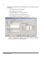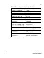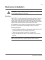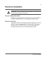
1
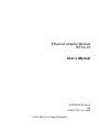
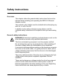
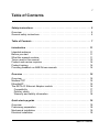
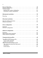
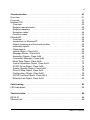
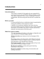
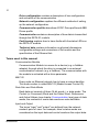
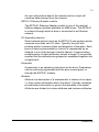
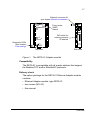
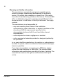
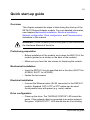
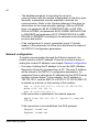
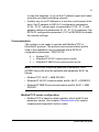
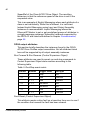
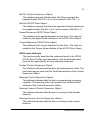
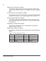
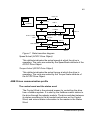
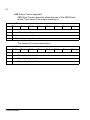
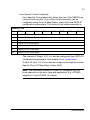
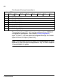
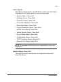
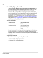
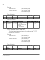
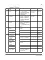
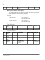
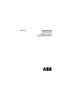
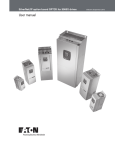
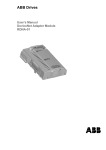
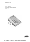
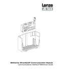
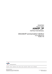
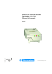
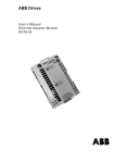
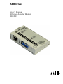
ABB Drives
User’s Manual
Ethernet Adapter Module
RETA-01
Ethernet Adapter Module
RETA-01
User’s Manual
3AFE64539736 Rev D
EN
EFFECTIVE: 23.3.2007
© 2007 ABB Oy. All Rights Reserved.
5
Safety instructions
Overview
This chapter states the general safety instructions that must be
followed when installing and operating the RETA-01 Ethernet
Adapter module.
The material in this chapter must be studied before attempting any
work on, or with, the unit.
In addition to the safety instructions given below, read the
complete safety instructions of the specific drive you are working
on.
General safety instructions
WARNING! All electrical installation and maintenance work on the
drive should be carried out by qualified electricians.
The drive and adjoining equipment must be properly earthed.
Do not attempt any work on a powered drive. After switching off
the mains, always allow the intermediate circuit capacitors
5 minutes to discharge before working on the frequency converter,
the motor or the motor cable. It is good practice to check (with a
voltage indicating instrument) that the drive is in fact discharged
before beginning work.
The motor cable terminals of the drive are at a dangerously high
voltage when mains power is applied, regardless of motor
operation.
There can be dangerous voltages inside the drive from external
control circuits even when the drive mains power is shut off.
Exercise appropriate care when working on the unit. Neglecting
these instructions can cause physical injury or death.
Safety instructions
6
Safety instructions
7
Table of Contents
Safety instructions . . . . . . . . . . . . . . . . . . . . . . . . . . . . . . . . . . . . . . . . . . . . 5
Overview . . . . . . . . . . . . . . . . . . . . . . . . . . . . . . . . . . . . . . . . . . . . . . . . . . . . 5
General safety instructions . . . . . . . . . . . . . . . . . . . . . . . . . . . . . . . . . . . . . . . 5
Table of Contents . . . . . . . . . . . . . . . . . . . . . . . . . . . . . . . . . . . . . . . . . . . . . 7
Introduction . . . . . . . . . . . . . . . . . . . . . . . . . . . . . . . . . . . . . . . . . . . . . . . . 11
Intended audience . . . . . . . . . . . . . . . . . . . . . . . . . . . . . . . . . . . . . . . . . . . .
Before you start . . . . . . . . . . . . . . . . . . . . . . . . . . . . . . . . . . . . . . . . . . . . . .
What this manual contains . . . . . . . . . . . . . . . . . . . . . . . . . . . . . . . . . . . . . .
Terms used in this manual . . . . . . . . . . . . . . . . . . . . . . . . . . . . . . . . . . . . . .
Product and service inquiries . . . . . . . . . . . . . . . . . . . . . . . . . . . . . . . . . . . .
Product training . . . . . . . . . . . . . . . . . . . . . . . . . . . . . . . . . . . . . . . . . . . . . .
Providing feedback on ABB Drives manuals . . . . . . . . . . . . . . . . . . . . . . . .
11
11
11
12
14
14
14
Overview . . . . . . . . . . . . . . . . . . . . . . . . . . . . . . . . . . . . . . . . . . . . . . . . . . . 15
Overview . . . . . . . . . . . . . . . . . . . . . . . . . . . . . . . . . . . . . . . . . . . . . . . . . . .
Modbus/TCP . . . . . . . . . . . . . . . . . . . . . . . . . . . . . . . . . . . . . . . . . . . . . . . .
EtherNet/IP . . . . . . . . . . . . . . . . . . . . . . . . . . . . . . . . . . . . . . . . . . . . . . . . . .
The RETA-01 Ethernet Adapter module . . . . . . . . . . . . . . . . . . . . . . . . . . .
Compatibility . . . . . . . . . . . . . . . . . . . . . . . . . . . . . . . . . . . . . . . . . . . . . . .
Delivery check . . . . . . . . . . . . . . . . . . . . . . . . . . . . . . . . . . . . . . . . . . . . .
Warranty and liability information . . . . . . . . . . . . . . . . . . . . . . . . . . . . . . .
15
15
15
16
17
17
18
Quick start-up guide . . . . . . . . . . . . . . . . . . . . . . . . . . . . . . . . . . . . . . . . . 19
Overview . . . . . . . . . . . . . . . . . . . . . . . . . . . . . . . . . . . . . . . . . . . . . . . . . . .
Preliminary preparation . . . . . . . . . . . . . . . . . . . . . . . . . . . . . . . . . . . . . . . .
Mechanical installation . . . . . . . . . . . . . . . . . . . . . . . . . . . . . . . . . . . . . . . . .
Electrical installation . . . . . . . . . . . . . . . . . . . . . . . . . . . . . . . . . . . . . . . . . . .
19
19
19
19
Table of Contents
8
Drive configuration . . . . . . . . . . . . . . . . . . . . . . . . . . . . . . . . . . . . . . . . . . . .
Network configuration . . . . . . . . . . . . . . . . . . . . . . . . . . . . . . . . . . . . . . . . . .
Communication . . . . . . . . . . . . . . . . . . . . . . . . . . . . . . . . . . . . . . . . . . . . . . .
Modbus/TCP master configuration . . . . . . . . . . . . . . . . . . . . . . . . . . . . . .
Ethernet/IP master configuration . . . . . . . . . . . . . . . . . . . . . . . . . . . . . . . .
19
20
21
21
22
Mechanical installation . . . . . . . . . . . . . . . . . . . . . . . . . . . . . . . . . . . . . . . . 29
Mounting . . . . . . . . . . . . . . . . . . . . . . . . . . . . . . . . . . . . . . . . . . . . . . . . . . . . 29
Electrical installation . . . . . . . . . . . . . . . . . . . . . . . . . . . . . . . . . . . . . . . . . 31
General cabling instructions . . . . . . . . . . . . . . . . . . . . . . . . . . . . . . . . . . . . . 31
Ethernet connection . . . . . . . . . . . . . . . . . . . . . . . . . . . . . . . . . . . . . . . . . . . 31
Drive configuration . . . . . . . . . . . . . . . . . . . . . . . . . . . . . . . . . . . . . . . . . . . 33
Overview . . . . . . . . . . . . . . . . . . . . . . . . . . . . . . . . . . . . . . . . . . . . . . . . . . . . 33
RETA-01 configuration . . . . . . . . . . . . . . . . . . . . . . . . . . . . . . . . . . . . . . . . . 33
Network configuration . . . . . . . . . . . . . . . . . . . . . . . . . . . . . . . . . . . . . . . . 41
Overview . . . . . . . . . . . . . . . . . . . . . . . . . . . . . . . . . . . . . . . . . . . . . . . . . . . . 41
Data transfer rates supported . . . . . . . . . . . . . . . . . . . . . . . . . . . . . . . . . . . . 44
Other network components . . . . . . . . . . . . . . . . . . . . . . . . . . . . . . . . . . . . . . 44
Communication profiles . . . . . . . . . . . . . . . . . . . . . . . . . . . . . . . . . . . . . . . 45
The ODVA AC/DC drive profile . . . . . . . . . . . . . . . . . . . . . . . . . . . . . . . . . . .
ODVA output attributes . . . . . . . . . . . . . . . . . . . . . . . . . . . . . . . . . . . . . . .
ODVA input attributes . . . . . . . . . . . . . . . . . . . . . . . . . . . . . . . . . . . . . . . .
ABB Drives communication profile . . . . . . . . . . . . . . . . . . . . . . . . . . . . . . . .
The control word and the status word . . . . . . . . . . . . . . . . . . . . . . . . . . . .
References . . . . . . . . . . . . . . . . . . . . . . . . . . . . . . . . . . . . . . . . . . . . . . . .
Actual values . . . . . . . . . . . . . . . . . . . . . . . . . . . . . . . . . . . . . . . . . . . . . . .
Table of Contents
45
46
47
49
49
50
50
9
Communication . . . . . . . . . . . . . . . . . . . . . . . . . . . . . . . . . . . . . . . . . . . . . 51
Overview . . . . . . . . . . . . . . . . . . . . . . . . . . . . . . . . . . . . . . . . . . . . . . . . . . .
Protocols . . . . . . . . . . . . . . . . . . . . . . . . . . . . . . . . . . . . . . . . . . . . . . . . . . .
Modbus/TCP . . . . . . . . . . . . . . . . . . . . . . . . . . . . . . . . . . . . . . . . . . . . . . . .
Overview . . . . . . . . . . . . . . . . . . . . . . . . . . . . . . . . . . . . . . . . . . . . . . . . . .
Register read and write . . . . . . . . . . . . . . . . . . . . . . . . . . . . . . . . . . . . . .
Register mapping . . . . . . . . . . . . . . . . . . . . . . . . . . . . . . . . . . . . . . . . . . .
Exception codes . . . . . . . . . . . . . . . . . . . . . . . . . . . . . . . . . . . . . . . . . . . .
Function codes . . . . . . . . . . . . . . . . . . . . . . . . . . . . . . . . . . . . . . . . . . . . .
EtherNet/IP . . . . . . . . . . . . . . . . . . . . . . . . . . . . . . . . . . . . . . . . . . . . . . . . . .
Overview . . . . . . . . . . . . . . . . . . . . . . . . . . . . . . . . . . . . . . . . . . . . . . . . . .
Introduction to Ethernet/IP . . . . . . . . . . . . . . . . . . . . . . . . . . . . . . . . . . . .
Object modelling and functional profiles . . . . . . . . . . . . . . . . . . . . . . . . . .
Assembly objects . . . . . . . . . . . . . . . . . . . . . . . . . . . . . . . . . . . . . . . . . . .
Class objects . . . . . . . . . . . . . . . . . . . . . . . . . . . . . . . . . . . . . . . . . . . . . .
Identity Object, Class 0x01 . . . . . . . . . . . . . . . . . . . . . . . . . . . . . . . . . . . .
Message Router, Class 0x02 . . . . . . . . . . . . . . . . . . . . . . . . . . . . . . . . . .
Assembly Objects, Class 0x04 . . . . . . . . . . . . . . . . . . . . . . . . . . . . . . . . .
Connection Manager, Class 0x06 . . . . . . . . . . . . . . . . . . . . . . . . . . . . . .
Motor Data Object, Class 0x28 . . . . . . . . . . . . . . . . . . . . . . . . . . . . . . . . .
Control Supervisor Object, Class 0x29 . . . . . . . . . . . . . . . . . . . . . . . . . . .
AC/DC-Drive Object, Class 0x2A . . . . . . . . . . . . . . . . . . . . . . . . . . . . . . .
Vendor Specific Object, Class 0x90 . . . . . . . . . . . . . . . . . . . . . . . . . . . . .
Drive IO Map Object, Class 0x91 . . . . . . . . . . . . . . . . . . . . . . . . . . . . . . .
Configuration Object, Class 0x92 . . . . . . . . . . . . . . . . . . . . . . . . . . . . . . .
TCP/IP Interface Object, Class 0xF5 . . . . . . . . . . . . . . . . . . . . . . . . . . . .
Ethernet Link Object, Class 0xF6 . . . . . . . . . . . . . . . . . . . . . . . . . . . . . . .
51
51
52
52
52
52
54
54
55
55
55
55
55
65
65
69
69
70
71
72
74
76
78
79
80
82
Fault tracing . . . . . . . . . . . . . . . . . . . . . . . . . . . . . . . . . . . . . . . . . . . . . . . . 83
LED indications . . . . . . . . . . . . . . . . . . . . . . . . . . . . . . . . . . . . . . . . . . . . . . 83
Technical data . . . . . . . . . . . . . . . . . . . . . . . . . . . . . . . . . . . . . . . . . . . . . . 85
RETA-01 . . . . . . . . . . . . . . . . . . . . . . . . . . . . . . . . . . . . . . . . . . . . . . . . . . . 85
Ethernet link . . . . . . . . . . . . . . . . . . . . . . . . . . . . . . . . . . . . . . . . . . . . . . . . . 86
Table of Contents
10
Table of Contents
11
Introduction
Intended audience
The manual is intended for the people who are responsible for
commissioning and using an RETA-01 Ethernet Adapter module.
The reader is expected to have a basic knowledge of electrical
fundamentals, electrical wiring practices and how to operate the
drive.
Before you start
It is assumed that the drive is installed and ready to operate before
starting the installation of the extension module.
In addition to conventional installation tools, have the drive
manuals available during the installation as they contain important
information not included in this manual. The drive manuals are
referred to at various points of this document.
What this manual contains
This manual contains information on the wiring, configuration and
use of the RETA-01 Ethernet Adapter module.
Safety instructions are featured in the first few pages of this
manual.
Overview contains a short description of the Ethernet protocols
and the RETA-01 Ethernet Adapter module, a delivery checklist,
and information on the manufacturer’s warranty.
Quick start-up guide contains a short description of how to set
up the RETA-01 Ethernet Adapter module.
Mechanical installation contains placing and mounting
instructions for the module.
Electrical installation contains wiring, bus termination and
earthing instructions.
Introduction
12
Drive configuration contains a description of bus configuration
and activation of the communication
Network configuration explains the different methods of setting
up the network configuration.
Communication profiles describes AC/DC Drive profile and ABB
Drives profile
Communication contains a description of how data is transmitted
through the RETA-01 module.
Fault tracing explains how to trace faults with the status LEDs on
the RETA-01 module.
Technical data contains information on physical dimensions,
configurable settings and connectors of the module and the
specification of the Ethernet link.
Terms used in this manual
Communication Module
Communication Module is a name for a device (e.g. a fieldbus
adapter) through which the drive is connected to an external
communication network (e.g. a fieldbus). The communication with
the module is activated with a drive parameter.
MAC ID
Every node on Ethernet network has to have a unique identifier.
This node number is called MAC ID (Media Access Control ID).
Data Sets and Data Words
Each data set consists of three 16-bit words, i.e. data words. The
Control (or Command) Word and the Status Word, References
and Actual Values (see chapter Communication) are types of data
words; the contents of some data words are user-definable.
Input and Output
The terms "input" and "output" are defined from the network
master's point of view. For example, drive's status words are
considered as the input data and control words as the output data.
Introduction
13
An input will produce data to the network and an output will
consume data received from the network.
RETA-01 Ethernet Adapter module
The RETA-01 Ethernet Adapter module is one of the optional
fieldbus adapter modules available for ABB drives. The RETA-01
is a device through which a drive is connected to an Ethernet
network.
I/O Assembly selection
Smart network devices (such as the RETA-01) can produce and/or
consume more than one I/O value. Typically, they will also
produce and/or consume status and diagnostic information. Each
piece of data communicated by a device is represented by an
attribute in one of the device’s internal objects. Communicating
multiple pieces of data (attributes) across a single I/O connection
requires that the attributes are grouped or assembled together into
a single block.
Parameter
A parameter is an operating instruction for the drive. Parameters
can be read and programmed with the drive control panel, or
through the RETA-01 module.
Attribute
Attribute is a description of a characteristic or feature of an object,
i.e. they contain information about the object. Typically, attributes
provide status information or govern the operation of an object.
Attributes are divided into class attributes and instance attributes.
Introduction
14
Product and service inquiries
Address any inquiries about the product to your local ABB
representative, quoting the type code and serial number of the unit
in question. A listing of ABB sales, support and service contacts
can be found by navigating to www.abb.com/drives and selecting
Drives – World wide service contacts on the right pane.
Product training
For information on ABB product training, navigate to
www.abb.com/drives and select Drives – Training courses on the
right pane.
Providing feedback on ABB Drives manuals
Your comments on our manuals are welcome. Go to
www.abb.com/drives, then select successively Drives – Document
Library – Manuals feedback form on the right pane.
Introduction
15
Overview
Overview
The RETA-01 Adapter module supports the Modbus/TCP and
EtherNet/IP network protocols. This chapter contains a short
description of the above protocols and the RETA-01 Adapter
module, a delivery checklist and warranty information.
Modbus/TCP
Modbus/TCP is a variant of the Modbus family of simple, vendorneutral communication protocols intended for supervision and
control of automation equipment. Specifically, it covers the use of
Modbus messaging in an Ethernet environment using the TCP/IP
protocols.
The implementation of the Modbus/TCP server in the RETA-01
module is done according to the Modbus/TCP Specification 1.0.
The supported Modbus commands are listed in chapter
Communication.
The Modbus/TCP protocol allows the RETA-01 module to be used
as an Ethernet bridge to control the drive. The RETA-01 module
supports eight simultaneous IP connections.
Further information can be obtained from www.modbus.org.
EtherNet/IP
EtherNet/IP is based on the Common Industrial Protocol (CIP),
which is also the framework for both the ControlNet and
DeviceNet networks. EtherNet/IP uses standard Ethernet and
TCP/IP technology to transport CIP communication packets. The
module fulfills all requirements for certification as an Ethernet/IP
device.
Further information can be obtained from www.odva.org.
Overview
16
The RETA-01 Ethernet Adapter module
The RETA-01 Ethernet Adapter module is an optional device for
ABB drives which enables the connection of the drive to a
Ethernet network. The drive is considered as a slave on the
Ethernet network. Through the RETA-01 Ethernet Adapter
module, it is possible to:
• give control commands to the drive
(Start, Stop, Run enable, etc.)
• feed a motor speed or torque reference to the drive
• give a process actual value or a process reference to the PID
controller of the drive
• read status information and actual values from the drive
• change drive parameter values
• reset a drive fault.
The Modbus/TCP and EtherNet/IP commands and services
supported by the RETA-01 Ethernet Adapter module are
discussed in chapter Communication. Please refer to the user
documentation of the drive as to which commands are supported
by the drive.
The adapter module is mounted into an option slot on the motor
control board of the drive. See the Hardware Manual of the drive
for module placement options.
Overview
17
Ethernet connector X1
(see chapter Electrical installation)
CHASSIS
RETA-01
PROFIBUS ADAPTER
GND
S1
IP
ADDRESS
Fixing screw
(GND)
(frame)
DIP switch for
selecting intranet
IP address
1 2 3 4 5 6 7 8
ON
Diagnostic LEDs
(See chapter
Fault tracing)
X1
NETWORK
NOT USED
LINK / ACTIVITY
MODULE STATUS
NETWORK STATUS
Top view
Side view
Figure 1. The RETA-01 Adapter module.
Compatibility
The RETA-01 is compatible with all master stations that support
the Modbus/TCP and/or EtherNet/IP protocols.
Delivery check
The option package for the RETA-01 Ethernet Adapter module
contains:
• Ethernet Adapter module, type RETA-01
• two screws (M3×10)
• this manual.
Overview
18
Warranty and liability information
The manufacturer warrants the equipment supplied against
defects in design, materials and workmanship for a period of
twelve (12) months after installation or twenty-four (24) months
from date of manufacturing, whichever first occurs. The local ABB
office or distributor may grant a warranty period different to the
above and refer to local terms of liability as defined in the supply
contract.
The manufacturer is not responsible for
• any costs resulting from a failure if the installation,
commissioning, repair, alternation, or ambient conditions of the
drive do not fulfil the requirements specified in the
documentation delivered with the unit and other relevant
documentation
• units subjected to misuse, negligence or accident
• units comprised of materials provided or designs stipulated by
the purchaser.
In no event shall the manufacturer, its suppliers or subcontractors
be liable for special, indirect, incidental or consequential damages,
losses or penalties.
If you have any questions concerning your ABB drive, please
contact the local distributor or ABB office. The technical data,
information and specifications are valid at the time of printing. The
manufacturer reserves the right to modifications without prior
notice.
Overview
19
Quick start-up guide
Overview
This chapter presents the steps to take during the start-up of the
RETA-01 Ethernet Adapter module. For more detailed information,
see chapters Mechanical installation, Electrical installation,
Network configuration, Drive configuration, and Communication
elsewhere in this manual.
WARNING! Follow the safety instructions given in this manual and
the Hardware Manual of the drive.
Preliminary preparation
• Before installation of the module, write down the MAC ID of the
module (printed on a sticker on the back of the module).
• Make sure you have the two screws for fastening the module.
Mechanical installation
• Insert the RETA-01 into its specified slot in the drive (SLOT2 for
ACS550, SLOT1 for ACS800).
• Fasten the two screws.
Electrical installation
• Connect the Ethernet cable (RJ-45 connector) to the RETA-01
module. Standard CAT 5 UTP or STP cables can be used.
Avoid parallel runs with power (e.g. motor) cables.
Drive configuration
• Power up the drive. The “MODULE STATUS” LED should be
green. If the network cable is connected to an active network,
the green “LINK/ACTIVITY” LED should also be lit or blinking.
Quick start-up guide
20
• The detailed procedure of activating the drive for
communication with the module is dependent on the drive type.
Normally, a parameter must be adjusted to activate the
communication. Refer to the Firmware Manual of the drive for
information on the communication settings. With an ACS550
drive, set parameter 98.02 COMM PROT SEL to EXT FBA.
With an ACS800, set parameter 98.02 COMM. MODULE LINK
to FIELDBUS and parameter 98.07 COMM PROFILE to ABB
DRIVES or GENERIC according to the selected communication
protocol and profile.
• If the configuration is correct, parameter group 51 should
appear in the parameter list of the drive and show the status of
the RETA-01 configuration parameters.
Network configuration
To enable communication through the Ethernet network, the
module needs a valid IP address. There are numerous ways of
setting the module IP address; see chapter Network configuration.
• One way of setting the IP address is to use the ARP (Address
Resolution Protocol) command from a PC. The new IP address
will be stored in the RETA-01 configuration parameters. An
example of how to change the IP address from the DOS Prompt
window is shown below. In the example, the IP address is
192.100.100.1, and the MAC ID is 00-30-11-FF-00-53 (MAC ID
is printed on a sticker on the housing of the module).
arp -s <192.100.100.1> <00-30-11-FF-00-53>
ping <192.100.100.1>
arp -d <192.100.100.1>
If the connection is established, the module answers:
Reply from 192.100.100.1: bytes=32 time=1ms
TTL=28
...
If the connection is not established, the DOS prompts:
Request timed out.
Request timed out.
...
Quick start-up guide
21
In case this happens, try to set the IP address again and make
sure that you typed everything correctly
• Another way to set IP address is to use the control panel of the
drive. Set IP address to RETA-01 configuration parameters
51.04 - 51.07, subnet mask to parameters 51.08 - 51.11 and
gateway address to parameters 51.12 - 51.15 if necessary. Set
RETA-01 configuration parameter 51.27 to REFRESH to enable
the network settings.
Communication
The module is now ready to operate with Modbus/TCP or
EtherNet/IP protocol. The protocol and communication profile
used in the application can be selected with a RETA-01
configuration parameter, “PROTOCOL”:
0 =
1 =
2 =
Modbus/TCP
EtherNet/IP AC/DC communication profile
EtherNet/IP ABB Drives communication profile
Note: With ACS550 the profile selection is automatic. With
ACS800 the profile must be selected with parameter 98.07 as
follows:
• Modbus/TCP: 98.07 = ABB DRIVES
• Ethernet/IP AC/DC communication profile: 98.07 = GENERIC
• Ethernet/IP ABB Drives communication profile: 98.07 = ABB
DRIVES
Modbus/TCP master configuration
• Modbus/TCP is based on data registers, which hold IO and
parameter values. See chapter Communication for register
mapping and supported function codes.
Quick start-up guide
22
Ethernet/IP master configuration
• Add RETA-01 adapter to device configuration
Figure 2. RSlogix 5000: Adding new module to I/O Configuration.
• Set “comm Format” to “Data-INT”, IP address, input and output
assemblies and their sizes. Disable the “Configuration”
assembly instance (1) by setting its size to ‘0’.
Quick start-up guide
23
• Use Class Instance Editor to edit the attributes of Ethernet/IP
objects if necessary.
Figure 3. RSNetWorks for Ethernet-IP: Class Instance Editor
Quick start-up guide
24
Example 1: Extended Speed Control (AC/DC communication profile)
on ACS800 Standard application
• Set “comm Format” to “Data-INT”
• Set IP address to ‘10.0.0.6’
• Set input assembly instance to ‘71’ and size to ‘2’
• Set output assembly instance to ‘21’ and size to ‘2’
• Set configuration instance to ‘1’ and size to ‘0’
Figure 4. RSlogix 5000: Setting up the Generic Ethernet Module
to use Extended Speed Control assembly
Quick start-up guide
25
Table 1. Drive configuration for Extended Speed Control
Drive parameter
Example setting for ACS800
10.01 EXT1 STRT/STP/DIR
COMM.CW
10.03 REF DIRECTION
REQUEST
11.03 EXT1 REF1 SELECT
COMM.REF
16.04 FAULT RESET SEL
COMM.CW
98.02 COMM. MODULE LINK
FIELDBUS
98.07 COMM PROFILE
GENERIC
51.01 MODULE TYPE
ETHERNET
51.02 COMM RATE
0 (Auto-negotiation)
51.03 DHCP
1 (Enabled)
51.04 - 51.07 IP ADDRESS
10.0.0.6
51.08 - 51.11 SUBNET MASK
255.255.255.0
51.12 - 51.15 GW ADDRESS
0.0.0.0
51.16 PROTOCOL
1 (AC/DC profile)
Quick start-up guide
26
Example 2: User Specific Control (ABB Drives communication profile)
on ACS550
• Set “comm Format” to “Data-INT”
• Set IP address to ‘10.0.0.6’
• Set input instance to ‘103’ and size to ‘3’
• Set output instance to ‘102’ and size to ‘2’
• Set configuration instance to ‘1’ and size to ‘0’
Figure 5. RSlogix 5000: Setting up the Generic Ethernet Module
to use User Specific Control assembly
Quick start-up guide
27
Table 2. Drive configuration for User Specific Control
Drive parameter
Example setting for ACS550
10.01 EXT1 COMMANDS
COMM
10.03 DIRECTION
REQUEST
11.03 REF1 SELECT
COMM
16.04 FAULT RESET SEL
COMM
98.02 COMM PROT SEL
EXT FBA
51.01 MODULE TYPE
ETHERNET
51.02 COMM RATE
0 (Auto-negotiation)
51.03 DHCP
1 (Enabled)
51.04 - 51.07 IP ADDRESS
10.0.0.6
51.08 - 51.11 SUBNET MASK
255.255.255.0
51.12 - 51.15 GW ADDRESS
0.0.0.0
51.16 PROTOCOL
2 (ABB Drives profile)
51.19 OUTPUT 1
1 (Command word)
51.20 OUTPUT 2
2 (Reference 1)
51.23 INPUT 1
4 (Status word)
51.24 INPUT 2
5 (Actual value 1)
51.25 INPUT 3
104 (Par. 1.04 CURRENT)
Quick start-up guide
28
Quick start-up guide
29
Mechanical installation
WARNING! Follow the safety instructions given in this manual and
in the Hardware Manual of the drive.
Mounting
The RETA-01 is to be inserted into its specific position in the drive.
The module is held in place with plastic retaining clips and two
screws. The screws also provide the earthing of the CAT 5 STP
cable shield connected to the module, and interconnect the GND
signals of the module and the control board of the drive.
On installation of the module, the signal and power connection to
the drive is automatically made through a 34-pin connector.
Mounting procedure:
• Insert the module carefully into its position inside the drive until
the retaining clips lock the module into position.
• Fasten the two screws (included) to the stand-offs.
• Set the IP address DIP switch of the module to the required
position.
Note: Correct installation of the screws is essential for fulfilling the
EMC requirements and for proper operation of the module.
Mechanical installation
30
Mechanical installation
31
Electrical installation
WARNING! Follow the safety instructions given in this manual and
in the Hardware Manual of the drive.
General cabling instructions
Arrange the network cable as far away from the motor cables as
possible. Avoid parallel runs. Use bushings at cable entries.
Ethernet connection
The network cable is connected to the RJ45 connector (X1) on the
RETA-01 module. Standard CAT 5 UTP and CAT 5 STP cables
can be used. In case CAT 5 STP is used, the cable shield is
internally connected to drive frame through the module.
Electrical installation
32
Electrical installation
33
Drive configuration
Overview
This chapter gives information on configuring the RETA-01
Ethernet Adapter module and the drive.
RETA-01 configuration
After the RETA-01 Ethernet Adapter module has been
mechanically and electrically installed according to the instructions
in chapters Mechanical installation and Electrical installation, the
drive must be prepared for communication with the module.
ABB drives can receive control information from multiple sources
including digital inputs, analogue inputs, the drive control panel
and a communication module (e.g. RETA-01). ABB drives allow
the user to separately determine the source for each type of
control information (Start, Stop, Direction, Reference, Fault Reset,
etc.). In order to give the fieldbus master station the most
complete control over the drive, the communication module must
be selected as source for this information.The detailed procedure
of activating the drive for communication with the module is
dependent on the drive type. Normally, a parameter must be
adjusted to activate the communication. Please refer to the drive
documentation.
As communication between the drive and the RETA-01 is
established, several configuration parameters are copied to the
drive. These parameters must be checked first and adjusted if
necessary. The alternative selections for these parameters are
discussed in more detail below the table.
Note: The new settings take effect only when the module is
powered up the next time or when the module receives a ‘Fieldbus
Adapter parameter refresh’ (Parameter 51.27) command from the
drive.
Drive configuration
34
Table 3. The RETA-01 configuration parameters
Par.
no.
Parameter name
Alternative settings
Default
setting
1
MODULE TYPE
(Read-only)
ETHERNET
2
Comm rate
(0) Auto-negotiate; (1) 100 Mbit/s,
full duplex; (2) 100 Mbit/s, half
duplex; (3) 10 Mbit/s, full duplex;
(4) 10 Mbit/s, half duplex
(0) Auto-negotiate
3
DHCP
(0) DHCP disabled; (1) DHCP
enabled
(1) DHCP enabled
4
IP address 1
0…255
0
5
IP address 2
0…255
0
6
IP address 3
0…255
0
7
IP address 4
0…255
0
8
Subnet mask 1
0…255
0
9
Subnet mask 2
0…255
0
10
Subnet mask 3
0…255
0
11
Subnet mask 4
0…255
0
12
GW address 1
0…255
0
13
GW address 2
0…255
0
14
GW address 3
0…255
0
15
GW address 4
0…255 (0)
0
16
Protocol
(0) Modbus/TCP;
(1) Ethernet/IP AC/DC
communication profile;
(2) Ethernet/IP ABB Drives
communication profile
(0) Modbus/TCP
17
Modbus timeout
0…65535
0
18
Stop function
(0) Ramp stop; (1) Coast stop
(0) Ramp stop
19
Output 1
0…65535
0
20
Output 2
0…65535
0
Drive configuration
35
21
Output 3
0…65535
0
22
Output 4
0…65535
0
23
Input 1
0…65535
0
24
Input 2
0…65535
0
25
Input 3
0…65535
0
26
Input 4
0…65535
0
1 MODULE TYPE
This parameter shows the module type as detected by the drive.
The value cannot be adjusted by the user.
If this parameter is undefined, the communication between the
drive and the module has not been established.
2 Comm rate
Defines the baud rate for the Ethernet interface.
0
1
2
3
4
=
=
=
=
=
Auto-negotiate
100 Mbit/s, full duplex
100 Mbit/s, half duplex
10 Mbit/s, full duplex
10 Mbit/s, half duplex
3 DHCP
The Dynamic Host Configuration Protocol (DHCP) is an Internet
protocol for automating the configuration of computers that use
TCP/IP. DHCP can be used to automatically assign IP addresses,
to deliver TCP/IP stack configuration parameters such as the
subnet mask and default router, and to provide other configuration
information.
0 = DHCP disabled
1 = DHCP enabled
Drive configuration
36
4 IP address 1
5 IP address 2
6 IP address 3
7 IP address 4
An IP address is assigned to each TCP/IP node on an Ethernet
network. IP addresses consist of four decimal integers in the
range of 0…255 separated by periods, each integer representing
the value of one byte (8 bits, octet) in the IP address. These
parameters define the four octets of the IP address.
Note: Setting any actuator of DIP switch S1 enables hardware
address selection, in which case the IP address is of the format
192.168.0.xxx. The fourth octet is defined by the DIP switch. See
chapter Network configuration.
8 Subnet mask 1
9 Subnet mask 2
10 Subnet mask 3
11 Subnet mask 4
Subnet masks are used for splitting networks into subgroups, or
subnets. A subnet mask is a binary pattern that is matched up with
the IP address to turn part of the address field into a field for
subnets. These parameters define the four octets of the subnet
mask.
12 GW address 1
13 GW address 2
14 GW address 3
15 GW address 4
Gateways connect individual physical networks into a system of
networks. When a node needs to communicate with a node on
another network, the gateway transfers the data between the two
networks. These parameters define the four octets of the gateway
address.
Drive configuration
37
16 Protocol
Selects the application protocol and communication profile for the
network communication.
0 = Modbus/TCP
1 = EtherNet/IP AC/DC communication profile
2 = EtherNet/IP ABB Drives communication profile
17 Modbus timeout
The Modbus protocol has no implementation for time-out on
application layer and this may be required when controlling a
drive. A supervision method has been implemented for this
purpose. If Modbus timeout is set to zero, this feature is disabled.
The unit of the parameter is 100 milliseconds (e.g. ‘22’ will give a
timeout of 2.2 seconds).
If the communication fault function of the drive is activated,
Modbus timeout is the sum of communication fault time and the
time defined here.
18 Stop function
Defines the motor stopping method.
0 = Ramp stop
1 = Coast stop
Note: This parameter is only effective if the EtherNet/IP network
protocol is selected at parameter 16 Protocol.
19 Output 1
20 Output 2
21 Output 3
22 Output 4
When Modbus/TCP protocol is in use, these parameters define
the output data words or drive parameters that are updated
cyclically between the drive and RETA-01. For the user this can be
seen as faster response for the Modbus queries.
Drive configuration
38
When Ethernet/IP protocol is in use, these parameters define the
data words or drive parameters that can be sent using Assembly
object instance 102 (see chapter Communication).
The contents are defined by a decimal number in the range of
0 to 65535 as follows:
0
1…99
Not used
Data set area of the drive
1
Data set 1 word 1
2
3
4
5
•••
99
101…9999
10000…65535
Data set 1 word 2
Data set 1 word 3
Data set 2 word 1
Data set 2 word 2
•••
Data set 33 word 3
Parameter area of the drive
Format: (x)xyy, where (x)x = actual
signal group or parameter group; yy
= actual signal or parameter index.
E.g. 103 = actual signal 01.03; 2202
= parameter 22.02.
Not supported by the drive
23 Input 1
24 Input 2
25 Input 3
26 Input 4
When Modbus/TCP protocol is in use, these parameters define
the input data words or drive parameters that are updated
cyclically between the drive and RETA-01. For the user this can be
seen as faster response for the Modbus queries.
When Ethernet/IP protocol is in use, these parameters define the
data words or drive parameters that can be read using Assembly
object instance 103 (see chapter Communication).
Drive configuration
39
The contents are defined by a decimal number in the range of
0 to 65535 as follows:
0
1…99
Not used
Data set area of the drive
1
Data set 1 word 1
2
3
4
5
•••
99
101…9999
10000…65535
Data set 1 word 2
Data set 1 word 3
Data set 2 word 1
Data set 2 word 2
•••
Data set 33 word 3
Parameter area of the drive
Format: (x)xyy, where (x)x = actual
signal group or parameter group; yy
= actual signal or parameter index.
E.g. 103 = actual signal 01.03; 2202
= parameter 22.02.
Not supported by the drive
Drive configuration
40
Drive configuration
41
Network configuration
Overview
The network configuration of the RETA-01 can be done using
several methods. The following flowchart shows the sequence in
which different settings are read. The table below gives detailed
information on each different configuration methods.
Start
DIP
switches
= 0?
Yes
No
Use
DHCP?
No
Yes
DHCP
server
timeout?
Yes
No
Use 192.168.0.xxx
(xxx = DIP setting)
Use configuration
from DHCP server
RETA-01 config
parameters
<> 0?
Yes
Wait for config
through Gleaning
No
Use stored
settings
Configuration
received?
No
Yes
End
Figure 6. Settings flowchart
Network configuration
42
Table 4. Configuration methods
Method
Description
DIP switch (S1) By default, the IP address is defined by
software (see chapter Communication).
Setting any DIP actuator to ON enables
hardware selection. DIP actuators 1 to 8
define the last octet (1 to 254) of the IP
address in binary. Actuator 8 represents the
least significant bit.
IP address:
192.168.0.xxx
Subnet mask:
255.255.255.0
Gateway:
0.0.0.0
where xxx stands for a value between 1 and
254 and is selected by DIP switch S1.
Example DIP settings:
Intranet IP
address
S1 actuator
positions
(Selected by
software)
OFF oooooooo
ON
12345678
192.168.0.1
OFF ooooooo
ON
o
12345678
192.168.0.2
OFF oooooo o
ON
o
12345678
•••
•••
192.168.0.255 OFF
ON oooooooo
12345678
Network configuration
Note
Only read at
start-up.
Only for intranet
use.
43
Method
Description
Note
DHCP/BOOTP Automatically receive the configuration from A DHCP server
a DHCP server.
is required on
the network.
Settings stored Use the configuration stored in the RETA-01
in RETA-01 configuration parameters. See Table 3 in the
configuration chapter Drive configuration.
parameters
Gleaning
(ARP)
RETA-01 must
be restarted or
parameters
refreshed
(RETA-01
configuration
parameter 27
'REFRESH') for
any configuration
changes to take
effect.
Change the IP address from a PC using the The MAC
following commands:
address of the
module can be
found on a label
arp -s <IP address> <MAC address>
on the RETA-01
ping <IP address>
module.
arp -d <IP address>
The arp -s command will store the IP and
MAC addresses in the PC ARP table. When
the ping command is executed, the PC will
send the message to the module using the
MAC address. The module changes its IP
address to the given one.
Network configuration
44
Method
Description
EtherNet/IP
Note
Send IP parameters to the TCP/IP Interface RETA-01 must
object (Class 0xF5).
be restarted or
parameters
refreshed
(RETA-01
configuration
parameter 27
'REFRESH') for
any configuration
changes to take
effect.
Data transfer rates supported
The RETA-01 supports 10 Mbit/s and 100 Mbit/s data transfer
rates. The RETA-01 automatically detects the data transfer rate
used.
Other network components
RETA-01 uses multicast messages for producing instances.
Ethernet switches require a feature called "IGMP Snooping"
(Internet Group Management Protocol) to avoid network load
caused by the multicast messages. IGMP Snooping simply
confirms that multicast messages are sent to correct devices.
Network configuration
45
Communication profiles
Overview
This chapter describes the communication profiles used in the
communication between the Modbus/TCP and Ethernet/IP
networks, the RETA-01 module, and the drive.
Communication profiles
Communication profiles are ways of conveying control commands
(Control word, Status word, references and actual values)
between the master station and the drive.
With the RETA-01 module, the Ethernet/IP network may employ
either the ODVA AC/DC drive profile or the ABB Drives profile.
Modbus/TCP network may employ only the ABB Drives profile.
The ODVA AC/DC drive profile
This section briefly describes the ODVA AC/DC Drive profiles.
Additional information can be obtained from www.odva.org.
An Ethernet/IP node is modelled as a collection of abstract
objects. Each object represents the interface to and behaviour of a
component within the product. The ODVA AC/DC Drive Profiles
define a collection of objects suitable for the control of AC and DC
drives. Objects supported by the RETA-01 Ethernet Adapter are
listed in section Class objects on page 65. Objects are defined by:
• Service
• Class
• Instance
• Attribute
• Behaviour
For example, to set the drive speed reference, the
Set_Attribute_Single service can be requested for Attribute
Communication profiles
46
SpeedRef of the Class AC/DC Drive Object. The resulting
behaviour is that the reference speed of the drive is set to the
requested value.
This is an example of Explicit Messaging where each attribute of a
class is set individually. While this is allowed, it is inefficient.
Instead Implicit Messaging using Input and Output Assembly
Instances is recommended. Implicit Messaging allows the
Ethernet/IP Master to set or get predefined groups of attributes in
a single message exchange. Assembly Instances supported by
the RETA-01 are listed and defined in chapter Communication,
page 55.
ODVA output attributes
This section briefly describes the instances found in the ODVA
AC/DC Drive Profiles output assemblies. Not all attributes listed
here will be supported by all output assembly instances.
Run Forward & Run Reverse (Control Supervisor Object)
These attributes are used to assert run and stop commands to
Control Supervisor Object state machine according to the
following table.
Table 5. Run/Stop event matrix
RunFwd
RunRev
Trigger event
Run type
0
0
Stop
N/A
0!1
0
Run
RunFwd
0
0!1
Run
RunRev
0!1
0!1
No action
N/A
1
1
No action
N/A
0!1
1
Run
RunRev
1
0!1
Run
RunFwd
Fault Reset (Control Supervisor Object)
This attribute resets a drive fault on a transition from zero to one if
the condition that caused the fault has been cleared.
Communication profiles
47
Net Ctrl (Control Supervisor Object)
This attribute requests that the drive Run/Stop command be
supplied locally (Net Ctrl = 0) or by the network (Net Ctrl = 1).
Net Ref (AC/DC Drive Object)
This attribute requests that the drive speed and torque references
be supplied locally (Net Ref = 0) or by the network (Net Ref = 1).
Speed Reference (AC/DC Drive Object)
This attribute is the speed reference for the drive. The units are
scaled by the Speed Scale attribute of the AC/DC Drive Object.
Torque Reference (AC/DC Drive Object)
This attribute is the torque reference for the drive. The units are
scaled by the Torque Scale attribute of the AC/DC Drive Object.
ODVA input attributes
This section briefly describes the instances found in the ODVA
AC/DC Drive Profiles input assemblies. Not all attributes listed
here will be supported by all input assembly instances.
Faulted (Control Supervisor Object)
This attribute indicates that the drive has experienced a fault. The
fault code may be read from the FaultCode attribute of the Control
Supervisor Object.
Warning (Control Supervisor Object)
This attribute indicates that the drive is experiencing a warning
condition. The warning code may be read from the WarnCode
attribute of the Control Supervisor Object.
Running Forward (Control Supervisor Object)
This attribute indicates that the drive is running in the forward
direction.
Running Reverse (Control Supervisor Object)
This attribute indicates that the drive is running in the reverse
direction.
Communication profiles
48
Ready (Control Supervisor Object)
This attribute indicates that the Control Supervisor Object state
machine (see “State” below) is in the Ready, Running or Stopping
state.
Ctrl From Net (Control Supervisor Object)
This attribute indicates if the Run/Stop command is being supplied
locally (Ctrl From Net = 0) or by the network (Ctrl From Net = 1).
Ref From Net (AC/DC Drive Object)
This attribute indicates if the Speed and Torque references are
being supplied locally (Ref From Net = 0) or by the network (Ref
From Net = 1).
At Reference (AC/DC Drive Object)
This attribute indicates the drive is operating at the specified
speed or torque reference.
State (Control Supervisor Object)
This attribute indicates the current state of the Control Supervisor
Object.
Table 6. Control supervisor states
State
Description
State
Description
0
Vendor Specific
4
Enabled
1
Startup
5
Stopping
2
Not Ready
6
Fault Stop
3
Ready
7
Faulted
Communication profiles
49
Power off
Non existent
state
Power on
condition
ALM=1
Faulted
Start-up
Power on
FaultRst
DEC=0
Not ready
Power on AND
RDY
Power on AND
not RDY
Ready
Fault stop
DEC=0
Stopping
FWD OR REV
Enabled
ALM=1
DEC=1
ALM=1
ALM=1
Figure 7. State transition diagram
Speed Actual (AC/DC Drive Object)
This attribute indicates the actual speed at which the drive is
operating. The units are scaled by the SpeedScale attribute of the
AC/DC Drive Object.
Torque Actual (AC/DC Drive Object)
This attribute indicates the actual torque at which the drive is
operating. The units are scaled by the Torque Scale attribute of
the AC/DC Drive Object.
ABB Drives communication profile
The control word and the status word
The Control Word is the principal means for controlling the drive
from a fieldbus system. It is sent by the fieldbus master station to
the drive through the adapter module. The drive switches between
its states according to the bit-coded instructions on the Control
Word, and returns status information to the master in the Status
Word.
Communication profiles
50
References
References are 16-bit words containing a sign bit and a 15-bit
integer. A negative reference (indicating reversed direction of
rotation) is formed by calculating the two’s complement from the
corresponding positive reference.
Actual values
Actual values are 16-bit words containing information on the
operation of the drive. The functions to be monitored are selected
by a drive parameter.
Note: For detailed description of the drive's control word, status
word, references and actual signals see the Firmware Manual of
the drive.
Communication profiles
51
Communication
Overview
This chapter describes the Modbus/TCP and EtherNet/IP
messaging used in the communication with the drive.
Protocols
The RETA-01 module supports the Modbus/TCP protocol
according to Modbus/TCP Specification 1.0, and the EtherNet/IP
protocol. User must select, which protocol to use.
Communication
52
Modbus/TCP
Overview
This chapter describes the Modbus/TCP communication protocol
for RETA-01. For detailed information on Modbus/TCP
communication, refer to Modbus/TCP protocol specification 1.0.
RETA-01 uses ABB Drives communication profile with
Modbus/TCP.
Register read and write
The drive parameter and data set information is mapped into a
4xxxx register area. This holding register area can be read from
an external device, and an external device can modify the register
values by writing to them.
There are no set-up parameters for mapping the data to the 4xxxx
register area. The mapping is pre-defined and corresponds
directly to the drive parameter grouping, which is being used by
the local drive control panel.
All parameters are available for reading. The parameter writes are
verified for correct value, and for valid register addresses. Some
parameters never allow writing (e.g. actual signals), some allow
writing only when the drive is stopped (e.g. set-up variables), and
some can be modified at any time.
Register mapping
The drive parameters are mapped to the 4xxxx area as follows:
40001…40096 are reserved for data sets
40101…49999 are reserved for parameters.
In this mapping, the thousands and hundreds correspond to the
group number, while the tens and ones correspond to the
parameter number within a group. Register addresses 4GGPP are
shown in the table below. In the table, GG represents the group
number while PP is the parameter index within the group.
Communication
53
Table 7. Parameter mapping
Parameter
4GGPP
GG
PP
Data sets
40001…40096
00 Data sets
01 Data word 1.1
02 Data word 1.2
03 Data word 1.3
04 Data word 2.1
05 Data word 2.2
06 Data word 2.3
07 Data word 3.1
…
94 Data word 32.1
95 Data word 32.2
96 Data word 32.3
40101…40199
01 Group 01
01 Index 01
02 Index 02
…
99 Index 99
40201…40299
02 Group 02
01 Index 01
02 Index 02
…
99 Index 99
…
…
…
49901…49999
99 Group 99
01 Index 01
02 Index 02
…
99 Index 99
Each data set consists
of 3 data words. For
example, ‘Data word
2.3’ refers to the 3rd
word in data set 2.
Parameters
Register addresses, which are not allocated to any drive
parameter or data set, are invalid. Attempting to read from or write
to such an address will make the Modbus/TCP interface return an
exception code to the controller.
Refer to the drive manuals for drive-specific information such as
the data sets supported, and parameter numbers. Data set
registers are updated in a cyclic interval. Updating of parameter
registers happens at a slower interval.
Communication
54
Exception codes
The RETA-01 supports the Modbus exception codes shown
below.
Table 8. Supported exception codes
Exception Name
code
Description
01
Illegal
function
Unsupported command
02
Illegal data
address
Address does not exist or is read/writeprotected
03
Illegal data
value
Value is outside minimum and maximum
limits. Parameter is read-only
Function codes
The RETA-01 supports the Modbus function codes shown below.
Table 9. Supported function codes
Function Name
code
Description
Modbus
class
03
Read
holding
registers
Reads the binary contents of the
holding registers (4X references)
in the slave.
0
06
Preset
single
register
Presets a value into a single
holding register (4X reference).
1
16 (10h)
Preset
multiple
registers
Presets values into a sequence of 0
holding registers (4X references).
23 (17h)
2
Read/Write Performs a combination of one
registers
read and one write operation in a
single Modbus transaction. The
function first reads a group of
4XXXX registers and then writes
new contents to a another group
of 4XXXX registers.
Communication
55
EtherNet/IP
Overview
This chapter describes the Ethernet/IP communication protocol for
RETA-01. For detailed information on Ethernet/IP communication,
refer to ODVA Ethernet/IP specifications Release 1.0.
Introduction to Ethernet/IP
Ethernet/IP is a protocol based on Common Industrial Protocol
(CIP) technology, which is also the framework for both DeviceNet
and ControlNet. Ethernet/IP specifies the wiring, and the data
transfer through the bus.
The RETA-01 module can act as a server on an EtherNet/IP
network.
Object modelling and functional profiles
One of the main features of EtherNet/IP is object modelling.
EtherNet/IP requires mandatory objects specified by ODVA in
addition to some vendor-specific objects. A group of objects can
be described with a Functional Profile. The RETA-01 realizes the
ODVA AC/DC Drive Functional Profile with additional features.
Assembly objects
I/O Assembly Instances may be referred to as Block Transfer of
data. Intelligent devices realizing a Functional Profile, such as the
RETA-01, have several objects. Since it is not possible to transmit
more than one object data through a single connection, it is
practical and more efficient to group attributes from different
objects into a single I/O connection using the Assembly object.
The Assembly object acts as a tool for grouping these attributes.
The RETA-01 uses static assemblies (in other words, fixed set of
object data), except for the User Specific Control assembly and
the Extended Speed Control Plus Drive Parameters assembly,
where user can select the I/O parameters.
Communication
56
The module has two communication profiles as represented
above, AC/DC drive profile and ABB Drives profile.
Assembly instances 20, 70, 21, 71, 121 and 171 are used in the
AC/DC drive profile and instances 100, 101, 102 and 103 in ABB
Drives profile. User selects the profile with RETA-01 configuration
parameter 16 PROTOCOL (with ACS800 also parameter 98.07 is
changed). The following table shows the possible combinations.
Table 10. Possible combinations of parameters
RETA-01 configuration
parameter 16
Output instances Input instances
0 = Modbus/TCP
-
-
1 = Ethernet/IP AC/DC
communication profile
20, 21, 121
70, 71, 103*,
171
2 = Ethernet/IP ABB Drives
communication profile
100, 102
101, 103
Note: Assembly instance 103 can be used with AC/DC drive
profile if it contains only drive parameters and not data sets.
Assembly instances 121 and 171 are supported from RETA-01
v2.06 onwards.
The following table shows the possible combinations of output and
input instances.
Table 11. Possible combinations of output and input instances
Possible instance combinations
Output
instance
Input instance Communication profile to be used
20
70
Generic Drive profile
71
Generic Drive profile
171
Generic Drive profile
103
Generic Drive profile (See note
above)
Communication
57
21
121
100
102
70
Generic Drive profile
71
Generic Drive profile
171
Generic Drive profile
103
Generic Drive profile (See note
above)
70
Generic Drive profile
71
Generic Drive profile
171
Generic Drive profile
103
Generic Drive profile (See note
above)
101
ABB Drives profile
103
ABB Drives profile
101
ABB Drives profile
103
ABB Drives profile
The following tables describe the predefined assembly instances
supported by the RETA-01.
Note: The terms "input" and "output" are defined from the network
master's point of view. For example, drive's status words are
considered as the input data and control words as the output data.
An input will produce data to the network and an output will
consume data received from the network.
Basic Speed Control assembly
The Basic Speed Control assembly is defined by ODVA AC/DC
Drive Profile. The format of the output assembly is:
Instance 20
Byte
Bit 7
Bit 6
Bit 5
0
Bit 4
Bit 3
Bit 2
Fault reset
Bit 1
Bit 0
Run fwd
1
2
Speed reference (Low byte)
3
Speed reference (High byte)
Communication
58
The format of the input assembly is:
Instance 70
Byte
Bit 7
Bit 6
Bit 5
Bit 4
Bit 3
0
Bit 2
Bit 1
Running 1
Bit 0
Faulted
1
2
Speed actual value (Low byte)
3
Speed actual value (High byte)
Note: If the Basic Speed Control or the Extended Speed Control
assembly is used, it must be ensured that the fieldbus is selected
as the drive control source and fieldbus specific (Generic Drive
profile) Control/Status Word format is selected instead of ABB
Drives profile.
Extended Speed Control assembly
The Extended Speed Control assembly is defined by ODVA
AC/DC Drive Profile. The format of the output assembly is:
Instance 21
Byte Bit 7
Bit 6
Bit 5
0
NetRef
NetCtrl
1
2
Speed reference (Low byte)
3
Speed reference (High byte)
Communication
Bit 4
Bit 3
Bit 2
Bit 1
Bit 0
Fault
reset
Run
Run
reverse forward
59
The format of the input assembly is:
Instance 71
Byte Bit 7
Bit 6
Bit 5
Bit 4
Bit 3
Bit 2
Bit 1
Bit 0
0
At
Ref
referenc From
e
Net
Ctrl
From
Net
Ready
Runnin Runnin Warning Faulted
g
g
reverse forward
1
Drive state
2
Speed actual value (Low byte)
3
Speed actual value (High byte)
Extended Speed Control plus Drive Parameters assembly
The Extended Speed Control plus Drive Parameters assembly is
composed of a part defined by the ODVA AC/DC Drive Profile and
a part that can be configured freely. The format of the output
assembly is (RETA-01 version 2.06 onwards):
Instance 121
Byte Bit 7
Bit 6
Bit 5
0
NetRef
NetCtrl
Bit 4
Bit 3
Bit 2
Bit 1
Bit 0
Fault
reset
Run
Run
reverse forward
1
2
Speed reference (Low byte)
3
Speed reference (High byte)
4
Output I/O 1 (Low Byte)
5
Output I/O 1 (High Byte)
6
Output I/O 2 (Low Byte)
7
Output I/O 2 (High Byte)
…
67
Output I/O 32 (Low Byte)
68
Output I/O 32 (High Byte)
The value of Output I/O 1 to 4 sets the data word or drive
parameter defined by Output I/O Par 1 to 4 respectively. See
chapter Drive configuration.
Communication
60
Output I/O from 1 to 32 can also be configured through the Vendor
Specific Drive I/O Map Object, class 0x91.
The format of the input assembly is:
Instance 171
Byte Bit 7
Bit 6
Bit 5
Bit 4
Bit 3
Bit 2
Bit 1
Bit 0
0
At
Ref
referenc From
e
Net
Ctrl
From
Net
Ready
Runnin Runnin Warning Faulted
g
g
reverse forward
1
Drive state
2
Speed actual value (Low byte)
3
Speed actual value (High byte)
4
Input I/O 1 (Low Byte)
5
Input I/O 1 (High Byte)
6
Input I/O 2 (Low Byte)
7
Input I/O 2 (High Byte)
…
67
Input I/O 32 (Low Byte)
68
Input I/O 32 (High Byte)
The value of Input I/O 1 to 4 sets the data word or drive parameter
defined by Input I/O Par 1 to 4 respectively. See chapter Drive
configuration.
Input I/O from 1 to 32 can also be configured through the Vendor
Specific Drive I/O Object (Class 91h).
Communication
61
Data definitions
Definitions of data in the assemblies are found in the classes
specified in the table below.
Table 12. Definitions of data in the assemblies
Name
CIP class
Class
Instance
Attribute
Name
Run Forward
Control Supervisor
1
3
Run1
Run Rev
Control Supervisor
1
4
Run2
Fault Reset
Control Supervisor
1
12
FaultRst
NetCtrl
Control Supervisor
1
5
NetCtrl
NetRef
AC/DC drive
1
4
NetRef
Speed
reference
AC/DC drive
1
8
SpeedRef
Faulted
Control Supervisor
1
10
Faulted
Warning
Control Supervisor
1
11
Warning
Running
Forward
Control Supervisor
1
7
Running1
Running
Reverse
Control Supervisor
1
8
Running2
Ready
Control Supervisor
1
9
Ready
CtrlFromNet
Control Supervisor
1
15
CtrlFromN
et
DriveState
Control Supervisor
1
6
State
RefFromNet
AC/DC Drive
1
29
RefFromN
et
At Reference
AC/DC Drive
1
3
At
Reference
Speed Actual
AC/DC Drive
1
7
SpeedActu
al
Communication
62
ABB Drives Control assembly
ABB Drive Control assembly allows the use of the ABB Drives
profile. The format of the output assembly is:
Instance 100
Byte Bit 7
Bit 6
Bit 5
Bit 4
0
Control Word (Low Byte)
1
Control Word (High Byte)
2
Set Speed (Low byte), Not scaled
3
Set Speed (High byte), Not scaled
Bit 3
Bit 2
Bit 1
Bit 0
Bit 2
Bit 1
Bit 0
The format of the input assembly is:
Instance 101
Byte Bit 7
Bit 6
Bit 5
Bit 4
0
Status Word (Low byte)
1
Status Word (High byte)
2
Actual Speed (Low byte), Not scaled
3
Actual Speed (High byte), Not scaled
Communication
Bit 3
63
User Specific Control assembly
User Specific Control assembly allows the use of the ABB Drives
communication profile. The content of this assembly can be
configured using Drive IO Map Object, class 0x91 and RETA-01
configuration parameters. The format of the output assembly is:
Instance 102
Byte Bit 7
Bit 6
Bit 5
0
Output I/O 1 (Low Byte)
1
Output I/O 1 (High Byte)
2
Output I/O 2 (Low Byte)
3
Output I/O 2 (High Byte)
Bit 4
Bit 3
Bit 2
Bit 1
Bit 0
…
63
Output I/O 32 (Low Byte)
64
Output I/O 32 (High Byte)
The content of Output I/O 1 to 4 can be configured from RETA-01
configuration parameters. See chapter Drive configuration.
Output I/O from 1 to 32 can also be configured through the Vendor
Specific Drive I/O Map Object (class 0x91).
Note: The maximum number of output I/O’s supported by the
drive depends on the drive type and application. E.g. ACS800
supports 12 and ACS550 15 outputs.
Communication
64
The format of the input assembly is:
Instance 103
Byte Bit 7
Bit 6
Bit 5
0
Input I/O 1 (Low Byte)
1
Input I/O 1 (High Byte)
2
Input I/O 2 (Low Byte)
3
Input I/O 2 (High Byte)
Bit 4
Bit 3
Bit 2
Bit 1
Bit 0
…
63
Input I/O 32 (Low Byte)
64
Input I/O 32 (High Byte)
The content of Input I/O 1 to 4 can be configured from RETA-01
configuration parameters. See chapter Drive configuration.
Input I/O from 1 to 32 can also be configured through the Vendor
Specific Drive I/O Object (Class 91h).
Note: The maximum number of input I/O’s supported by the drive
depends on the drive type and application. E.g. ACS800 supports
12 and ACS550 15 inputs.
Communication
65
Class objects
The objects implemented in the RETA-01 module are listed below
and described in further detail on the following pages.
• Identity Object, Class 0x01
• Message Router, Class 0x02
• Assembly Object, Class 0x04
• Connection Manager, Class 0x06
• Motor Data Object, Class 0x28
• Control Supervisor Object, Class 0x29
• AC/DC Drive Object, Class 0x2A
• Vendor Specific Object, Class 0x90
• Drive IO Map Object, Class 0x91
• Configuration Object, Class 0x92
• TCP/IP Interface Object, Class 0xF5
• Ethernet Link Object, Class 0xF6
NOTE: Some object attributes are not supported by every drive
application.
Identity Object, Class 0x01
This object provides identification of and general information
about the device.
Communication
66
Services
Class services:
Get Attribute All
Get Attribute Single
Instance services:
Get Attribute All
Get Attribute Single
Reset
Class Attributes
#
Attribute
name
Services Description
Dflt,Min,Max Data type
Get
1,1,1
UINT
Services Description
Dflt,
Min, Max
Data type
0x01 Vendor ID
Get
Identification of the
device vendor
46
UINT
0x02 Device Type
Get
Identification of the 2
general product type
UINT
0x03 Product Code Get
Assigned vendor
Drive
code to describe the dependent
device
(e.g. 101)
UINT
0x04 Revision
Get
Revision of the item
the Identity Object
represents
Array
[USINT
USINT]
0x05 Status
Get
Status of the Device 0,0,255
WORD
0x06 Serial
Number
Get
Serial Number of the N/A,N/A,
EtherNet module
N/A
UDINT
0x07 Product
Name
Get
Product
identification (32
characters max.)
0x01 Revision
Revision of the
Identity Object
Instance Attributes
#
Attribute
name
Communication
RETA-01 and Short String
xxx
67
Attribute explanations
Vendor ID
The Open DeviceNet Vendor Association Inc. (ODVA) and
ControlNet International manage vendor IDs. The ABB Vendor ID
is 46.
Device Type
The list of device types is managed by ODVA. It is used to identify
the device profile that a particular product is using.
E.g. 2 = AC drive, 13 = DC drive
Product Code
Every ABB drive type or application of the drive has a dedicated
product code.
Revision
Revision attribute, which consists of Major and Minor Revisions,
identifies the Revision of the RETA-01 application.
Status
This attribute represents the current status of the entire device. Its
value changes as the state of the device changes. The Status
attribute is a WORD, with the bit definitions in the table below.
Communication
68
Table 13. Bit definitions
Bit(s)
Type/Name
Definition
0
Owned
TRUE indicates the device (or an object within the
device) has an owner. Within the Master/Slave
paradigm the setting of this bit means that the
Predefined Master/Slave Connection Set has been
allocated to a master. Outside the Master/Slave
paradigm the meaning of this bit is to be defined.
1
2
Configured
3
4,5,6,7
8
9
10
11
Minor
Recoverable
Fault
Minor
Unrecoverable
Fault
Major
Recoverable
Fault
Major
Unrecoverable
Fault
12,13,14,15
Communication
Reserved, set to 0.
TRUE indicates the application of the device has
been configured to do something that differs from
the “out–of–box” default. This does not include
configuration of the communications.
Reserved, set to 0.
Extended device status information
0000 = Unknown
0010 = Faulted I/O connection
0011 = No I/O connection established
0100 = Non-volatile configuration bad
0110 = Connection in Run mode
0111 = Connection in Idle mode
TRUE indicates the device detected a recoverable
problem. The problem does not cause the device to
go into a faulted state.
TRUE indicates the device detected a
unrecoverable problem. The problem does not
cause the device to go into a faulted state.
TRUE indicates the device detected a problem,
which caused the device to go into the “Major
Recoverable Fault” state.
TRUE indicates the device detected a problem,
which caused the device to go into the “Major
Unrecoverable Fault” state.
Reserved, set to 0.
69
Serial Number
This attribute is a number used in conjunction with the Vendor ID
to form a unique identifier for each device.
Product Name
This text string should represent a short description of the
product/product family represented by the product code in
attribute 3.
Reset Service
The Identity object provides a reset service. There are two
different types of reset requests:
• Type 0: ‘Power Cycling Reset’. This service emulates a power
cycling of the module.
• Type 1: ‘Out of box reset’. This service sets a “out-of-box”
configuration for the drive and performs a reset for the module.
Message Router, Class 0x02
Services
Class services:
–
Instance services:
–
Assembly Objects, Class 0x04
The Assembly Objects binds attributes of multiple object together.
This allows data of the objects to be sent and received over a
single connection. Assembly objects can be used to bind input
data or output data. The terms “input” and “output” are defined
from the network’s point of view. An input will produce data to the
network and an output will consume data received from the
network.
Communication
70
Services
Class services:
Get Attribute Single
Instance services:
Get Attribute Single
Set Attribute Single
Class Attributes
#
Name
0x01 Revision
Services Description
Dflt,Min,Max Data type
Get
0x0002
Revision 2
UINT
Instance Attributes
#
Name
0x03 Data
Services Description
Dflt,Min,Max Data type
Get / Set
N/A, N/A, N/A Array
[BYTE]
Data produced /
consumed by
module
Instances are presented above in Communication - Assembly
objects.
Connection Manager, Class 0x06
Class 1 Connections
Class 1 connections are used to transfer I/O data, and can be
established to the assembly object instances. Each class 1
connection establishes two data transports, one consuming and
one producing. The heartbeat instance is used for connections
that shall access only inputs or outputs. Total number of supported
class 1 connections is 31.
The first four bytes consumed by the device are defined as status
information (32-bit run/idle header). The header is not a
requirement in the EtherNet/IP specification, but most masters
today use this header. The module strips off the first four bytes of
data consumed by the device and interprets the Run/Idle bit.
Run/Idle operation for AC/DC Drive profile can be defined in
Control Supervisor Object’s (Class 0x29) attribute NetIdleMode
(20) and for ABB Drives profile in Configuration Object (Class
0x92) attribute IdleAction (7). (RETA-01 version 2.05 onwards)
Communication
71
Class 3 Connections
Class 3 connections are used to establish connections to the
message router. Thereafter the connection is used for explicit
messaging. Class 3 connections use TCP connections. The
Message router supports 16 simultaneous class 3 connections.
Rated packet Interval
The module supports a minimum RPI rate of 10 ms, and a
maximum of 3200 ms, for connections where the module is the
connection producer. Consuming connections are unlimited.
Motor Data Object, Class 0x28
This object serves as a database for motor parameters.
Services
Class services:
Get Attribute Single
Instance services:
Get Attribute Single
Set Attribute Single
Communication
72
Instance 0x01, Attributes
ID#
Attribute
name
Services Description
Motor
type
Dflt,
Min,
Max
Data type
0x03
Motor type
Get
AC/DC
7,7,7
UINT
0x06
Rated
Current
Get/Set
Rated Stator
Current from
motor nameplate.
AC/DC
UINT
0x07
Rated
Voltage
Get/Set
Rated Base
Voltage from
motor nameplate.
AC/DC
UINT
0x08
Rated Power Get/Set
Rated Power at
Rated
Frequency
AC/DC
0x09
Rated
Frequency
Get/Set
AC
UINT
0x0C Pole Count
Get
AC
UINT
0x0F
Get/Set
AC/DC
UINT
Base Speed
Control Supervisor Object, Class 0x29
This object models all the management functions for devices
within the “Hierarchy of Motor Control Devices” and is active only
when using AC/DC Drive profile. The behaviour of motor control
devices is described below in Table 5. Run/Stop event matrix and
Figure 7. State transition diagram.
Services supported
Class services:
Get Attribute Single
Instance services:
Reset
Get Attribute Single
Set Attribute Single
Communication
73
Instance 0x01 attributes
ID#
Attribute
name
Services Description
Data type
0x03 Run 1 1)
Get/Set
0 = Stop, 1 = Run
BOOL
2)
Get/Set
0 = Stop, 1 = Run
BOOL
0x05 Net Control 2) Get/Set
0 = Local Control,
1 = Network Control
BOOL
0x06 State
Get
1 = Start/up
2 = Not ready
3 = Ready
4 = Enabled
5 = Stopping
6 = FaultStop
7 = Faulted
UINT8
0x07 Running 1 3)
Get
0 = Stopped,
1 = Running
BOOL
0x08 Running 2 4)
Get
0 = Stopped,
1 = Running
BOOL
0x09 Ready
Get
1 = Ready, Enabled or Stopping 0 = BOOL
Other state
0x0A Faulted
Get
0 = Not faulted,
1 = Fault occurred
BOOL
0x0B Warning
Get
0 = No Warnings present,
1 = Warning
BOOL
0x0C FaultRst
Get/Set
0 ! 1 Fault Reset
BOOL
0x0D Fault Code
Get
The fault that caused the last
transition to the Faulted state.
UINT16
0x0F CtrlFromNet
Get
0 = NetControl disabled,
1 = NetControl enabled
BOOL
0x11 Force Fault
Get/Set
0 ! 1 Force a fault
BOOL
0x12 Force Status
Get
0 = Not Forced Non-zero = Forced
BOOL
0x04 Run 2
Communication
74
0x14 Net Idle
Mode 5)
Get/Set
0 = Stop (default)
1 = Ignore Idle
2 = Imitate communication fault
function
1)
Supported only with assembly instances 20, 21 and 121
2)
Supported only with assembly instances 21 and 121
3)
Supported only with assembly instances 70, 71 and 171
4)
Supported only with assembly instances 71 and 171
5)
Supported only from RETA-01 version 2.05 onwards
USINT
AC/DC-Drive Object, Class 0x2A
This object models the functions specific to an AC or DC Drive
and is accessible only when using AC/DC Drive profile.
Services Supported
Class services:
Get Attribute Single
Instance services:
Get Attribute Single
Set Attribute Single
Communication
75
Instance 0x01, Attributes
ID#
Attribute name Services Description
0x03 At Reference
Data type
Get
Frequency arrival
Get/Set
Requests torque or speed reference BOOL
to be local or from the network.
0 = Set Reference not net Control 1
= Set Reference at net Control Note
that the actual status of torque or
speed reference is reflected in
attribute RefFromNet 0x1D (29).
0x06 Drive Mode
Get
0 = Vendor specific
UINT8
0x07 Speed Actual
Get
Units RPM/2SpeedScale
SINT16
0x08 SpeedRef
Get/Set
Units RPM/2SpeedScale
SINT16
0x09 Current Actual
Get
Units 100 msec/2CurrentScale
UINT16
0x04 NetRef
2)
PowerScale
BOOL
UINT18
0x0A Power Actual
Get
Units Watts/2
0x0B Torque Actual
Get
Units Nm/2TorqueScale
UINT16
0x12 AccelTime
Get/Set
Units msec/2TimeScale
UINT16
0x13 DecelTime
Get/Set
Units msec/2TimeScale
UINT16
0x14 Low speed limit Get/Set
SpeedScale
Units RPM/2
UINT16
0x15 High speed limit Get/Set
Units RPM/2SpeedScale
UINT16
0x16 Speed Scale
Get/Set
Speed scaling factor
UINT8
0x17 Current Scale
Get/Set
Current scaling factor
UINT8
0x18 Torque Scale
Get/Set
Torque scaling factor
UINT8
0x1A Power Scale
Get/Set
Power scaling factor
UINT8
0x1B Voltage Scale
Get/Set
Voltage scaling factor
UINT8
0x1C Time Scale
Get/Set
Time scaling factor
UINT8
0x1D Ref From Net
Get
0x1F Field I or IV
Get/Set
2)
BOOL
Always to be set to 0
-
Supported only with assembly instance 21
Communication
76
Vendor Specific Object, Class 0x90
The Vendor Specific Object, Class 0x90, enables access of drive
parameter and data sets.
Services
Class services:
Get Attribute Single
Instance services:
Get Attribute Single
Set Attribute Single
To access drive parameters, Instance and Attribute must
correspond to the drive parameter Group and Index as follows:
• Instance = parameter Group (1…99)
• Attribute = parameter (1…99)
For example, Parameter 99.01 is accessed when:
• Class = 144 = 0x90
• Instance = 99 = 0x63
• Attribute = 1 = 0x01
Instance 0x01 (Group 1), Attributes
ID#
Attribute name
Services
Description
0x01
Parameter Index
Get/Set
Group 1 Index 1
0x02
Parameter Index
Get/Set
Group 1 Index 2
Parameter Index
Get/Set
Group 1 Index 99
…
0x63
Instance 0x02 (Group 2), Attributes
ID#
Attribute name
Services
Description
0x01
Parameter Index
Get/Set
Group 2 Index 1
0x02
Parameter Index
Get/Set
Group 2 Index 2
Parameter Index
Get/Set
Group 2 Index 99
…
0x63
…
Communication
77
Instance 0x63 (Group 99), Attributes
ID#
Attribute name
Services
Description
0x01
Parameter Index
Get/Set
Group 99 Index 1
0x02
Parameter Index
Get/Set
Group 99 Index 2
Parameter Index
Get/Set
Group 99 Index
99
…
0x63
To access data sets, Instance is always 100. Attribute corresponds
to a specific data word. For example, data set 2 word 1 is
accessed as follows:
• Class = 144 = 0x90
• Instance = 100 = 0x64
• Attribute = 4 = 0x04
Instance 0x64 (Datasets), Attributes
ID#
Attribute name
Services
Description
0x01
Data word index
Get/Set
Data Set 1 Word 1
0x02
Data word index
Get/Set
Data Set 1 Word 2
0x03
Data word index
Get/Set
Data Set 1 Word 3
0x04
Data word index
Get/Set
Data Set 2 Word 1
0x05
Data word index
Get/Set
Data Set 2 Word 2
0x06
Data word index
Get/Set
Data Set 2 Word 3
0x07
Data word index
Get/Set
Data Set 3 Word 1
Data word index
Get/Set
Data Set 33 Word 3
…
0x63
Communication
78
Drive IO Map Object, Class 0x91
This is a vendor specific object that is used for mapping data to
the User Specific Control assembly instances 102 and 103 and
Extended Speed Control plus Drive Parameters assembly
instances 121 and 171. Same mapping is used for both of the
control assemblies. The active control assembly is selected with
the configuration parameter PROTOCOL. Input and Output
parameters 1 to 4 correspond to the input and output parameters
represented in Table 3. The RETA-01 configuration parameters.
See chapter Drive configuration. Maximum of 32 words of Input
and Output can be defined in total.
Services Supported
Class services:
Get Attribute Single
Reset
Instance services:
Get Attribute Single
Set Attribute Single
Reset
A reset command to the class will clear mappings in all instances.
A reset command to an instance will clear all mappings in that
instance. Reset command can be used only when the assembly is
not active.
Instance and Attributes
Two instances are supported by Class 0x91:
• Instance 1 for Output parameters
• Instance 2 for Input parameters.
Communication
79
Instance 0x01 (Instances 102 and 121 parameters), Attributes
ID#
Attribute name
Dflt,Min,Max
Description
0x01 Output I/O parameter 1
0,0,32767
UINT16
0x02 Output I/O parameter 2
0,0,32767
UINT16
0x03 Output I/O parameter 3
0,0,32767
UINT16
0x04 Output I/O parameter 4
0,0,32767
UINT16
0x20 Output I/O parameter 32 0,0,32767
UINT16
…
Instance 0x02 (Instance 103 and 171 parameters), Attributes
ID#
Attribute name
Dflt,Min,Max
Description
0x01 Input I/O parameter 1
0,0,32767
UINT16
0x02 Input I/O parameter 2
0,0,32767
UINT16
0x03 Input I/O parameter 3
0,0,32767
UINT16
0x04 Input I/O parameter 4
0,0,32767
UINT16
0,0,32767
UINT16
…
0x20 Input I/O parameter 32
Note: Input and Output attributes can also be accessed with
RETA-01 configuration parameters 19-26.
Configuration Object, Class 0x92
This object is used to set the Idle action in ABB Drives profile.
Most Ethernet/IP masters implement the Run/Idle header and this
class was created to be able to define the drive behaviour in Idle
mode (RETA-01 version 2.05 onwards).
Communication
80
Services
Class services:
Get Attribute Single
Instance services:
Get Attribute Single
Set Attribute Single
Class Attributes
#
Name
0x01 Revision
Services Description
Dflt,Min,Max Data type
Get
0x0002
Revision 2
UINT
Instance Attributes
#
Name
Services Description
0x07 Idle Action
Get / Set
Dflt,Min,Max Data type
0, 0, 1
0 = Imitate
communication fault
function
1 = Ignore idle
UINT
TCP/IP Interface Object, Class 0xF5
This object provides a mechanism of configuring the TCP/IP
settings via EtherNet/IP.
Services
Class services:
Get Attribute All
Get Attribute Single
Instance services:
Get Attribute All
Get Attribute Single
Set Attribute Single
Class Attributes
#
Attribute
name
Services Description
Dflt,Min,Max Data type
1
Revision
Get
0x0001
Communication
Revision 1
UINT
81
Instance 1 Attributes
ID# Attribute
name
0x01 Status
Services Description
Dflt,Min,Max Data type
Get
1 = The interface
configuration attribute
contains a valid
configuration
Interface configuration
attribute is adjustable.
Capable of obtaining
network configuration
via DHCP.
0 = Configuration from
RETA-01 configuration
parameters;
2 = Configuration from
DHCP
Physical link -> Ethernet
object
00000001h,
N/A, N/A
DWORD
00000014h,
N/A, N/A
DWORD
N/A, 0, 2
DWORD
Path size
2 words
0x0002
Path
Ethernet class, Instance 20 F6 24 01
1
0x02 Configuration Get
Capability
0x03 Configuration Get/Set
Control
0x04 Physical Link Get
Object
0x05 Interface
Get/Set
Configuration
Current IP
address
Current
subnet mask
Current
gateway
address
Not used
Module’s IP address
Array[]
UINT
Padded
EPATH
Array[]
N/A, N/A, N/A UDINT
Module’s Network mask N/A, N/A, N/A UDINT
Module’s Gateway
address
N/A, N/A, N/A UDINT
Default domain name
for not fully qualified
host names
N/A, N/A, N/A STRING
Not used
Default
domain name
Communication
82
0x06 Host Name
Get/Set
Host name of the
module
N/A, N/A, N/A STRING
Ethernet Link Object, Class 0xF6
This object maintains link-specific counters and status information
for the Ethernet communication interface.
Services
Class services:
Get Attribute All
Get Attribute Single
Instance services:
Get Attribute All
Get Attribute Single
Class Attributes
ID#
Attribute
name
0x01 Revision
Services Description
Dflt,Min,Max Data type
Get
0001h
Revision 1
UINT
Instance Attributes
ID#
Attribute
name
Services Description
Dflt,Min,Max Data type
0x01 Interface
Speed
Get
10 or 100 Mbps
N/A, N/A, N/A UDINT
0x02 Interface
Flags
Get
–
N/A, N/A, N/A DWORD
0x03 Physical
Address
Get
Ethernet MAC
address of the
module
N/A, N/A, N/A Array
[6×USINT]
Communication
83
Fault tracing
LED indications
The RETA-01 module is equipped with three diagnostic LEDs. The
description of the LEDs is shown below.
(not used)
Network Status
Module Status
Network Status
Link/Activity
Name
Link/Activity
Module Status
Colour Function
Green
Flashing green - Module is receiving/transmitting
on Ethernet
Steady green - Module has detected link
Off - Module cannot detect link
Red/
Green
Flashing red - EtherNet/IP: One or more
connections timed out; Modbus/TCP: No message
has been received within configured time
Steady red - Duplicate IP address
Flashing green - Waiting for connections
Steady green - EtherNet/IP: At least one
EtherNet/IP connection is open against the
module (even to the Message router); Modbus/
TCP: At least one Modbus/TCP connection is
open against the module
Red/
Green
Flashing red - Minor fault (e.g. communication
with application lost but recoverable)
Steady red - Major fault (e.g. bad flash, failed
memory test, non-recoverable communication
problem with host)
Steady green - Normal operation
Fault tracing
84
Fault tracing
85
Technical data
RETA-01
Enclosure:
34 mm
CHASSIS
RETA-01
PROFIBUS ADAPTER
S1
IP
ADDRESS
1 2 3 4 5 6 7 8
ON
NETWORK
95 mm
GND
X1
NOT USED
LINK / ACTIVITY
MODULE STATUS
NETWORK STATUS
62 mm
20
mm
Figure 8. Enclosure of RETA-01
Mounting: Into the option slot on the control board of the drive.
Degree of protection: IP20
Ambient conditions: The applicable ambient conditions specified
for the drive in its Hardware Manual are in effect.
Settings:
• Parameters (set through the drive)
• 8-way DIP switch for intranet IP address selection
Connectors:
• 34-pin parallel bus connector
• RJ-45 connector
Technical data
86
Current consumption:
• 380 mA average (5 V), supplied by the control board of the drive
General:
• Estimated min. lifetime: 100 000 h
• All materials UL/CSA-approved
• Complies with EMC standards EN 50081-2 and EN 50082-2
Ethernet link
Compatible devices: Ethernet standard IEEE 802.3 and 802.3u
devices
Medium: 10base-TX or 100base-TX
• Termination: Internal
• Wiring: CAT 5 UTP, CAT 5 FTP* or CAT 5 STP*
(*Recommended)
• Connector: RJ-45
• Maximum segment length: 100 m
Topology: Bus, star
Serial communication type: Half and full Duplex
Transfer rate: 10/100 Mbps
Carrier protocol: TCP/IP
Application protocols:
• EtherNet/IP
• Modbus/TCP
Technical data
3AFE64539736 Rev D / EN
EFFECTIVE: 23.3.2007
ABB Oy
AC Drives
P.O. Box 184
FIN-00381 HELSINKI
FINLAND
Telephone +358 10 22 11
Fax
+358 10 22 22681
Internet
www.abb.com
ABB Inc.
Automation Technologies
Drives & Motors
16250 West Glendale Drive
New Berlin, WI 53151
USA
Telephone
262 785-3200
800-HELP-365
Fax
262 780-5135
ABB Beijing Drive Systems
Co. Ltd.
No. 1, Block D,
A-10 Jiuxianqiao Beilu
Chaoyang District
Beijing, P.R. China, 100015
Telephone +86 10 5821 7788
Fax
+86 10 5821 7618
Internet
www.abb.com