1
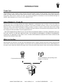
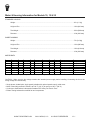
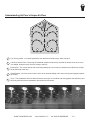
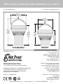
INSTALLATION & OPERATING GUIDE FOR MODELS 10, 15 AND 25
Air Pear Model Numbers:
10, 15 and 25. All voltages and colors.
12.8 in
(325mm)
12.8 in
(444mm)
17.5 in
12.25 in
(311mm)
(413mm)
16.25 in
(546mm)
21.5 in
(325mm)
SHORT
STANDARD
AIRIUS, LLC (Manufacturer)
811 South Sherman St.
Longmont, Colorado 80501 - USA
Toll free: 1-888-Air-Pear (247-7327)
Telephone: 303-772-2633
Fax: 303-772-8276
Email: [email protected]
Web: www.theairpear.com
Installation Guide: V1.1
May be covered by one or more of
the following United States Patents:
7,381,129 B2; D514688 and other patents pending
AIRIUS®, AIR PEAR®, and THE THERMAL EQUALIZER®
are trademarks of Airius, LLC, registered in the U.S.
and in some countries abroad. Other trademarks
pending in the U.S. and abroad.
AIRIUS Pty Ltd. (Exclusive Importer)
P/O Box 6282
Alexandria NSW 2015
Telephone: +61 2 8084 8524
Email: [email protected]
Airius, LLC, Copyright 2013
PC/ABS
WWW.THEAIRPEAR.COM
AIRIUS Europe Ltd. (Exclusive Importer)
2 Longham Business Centre
168 Ringwood Road, Ferndown, Dorset
BH22 9BU – United Kingdom
Telephone: +44 (0) 1202 554200
Fax: +44 (0) 1202 554396
Email: [email protected]
Web: www.airius.co.uk
©2013 AIRIUS, LLC
ALL RIGHTS RESERVED
V1.1
CONTENTS
INTRODUCTION
Thank You
About Models 10, 15 and 25
What’s in the Box
Motor & Housing Information
Safety Precautions
1
1
1
2
3
PRE-INSTALLATION
Preparing the Work Site
Tools Needed
Fan Diagram
Understanding Air Pear Air Flow
5
6
6
7
INSTALLATION
Power Requirements
Plug Wiring
Speed Control Wiring
Suggested Installation Methods
Suspended Ceiling Kit Assembly & Installation
8
9
10
11
14
OPERATING THE FAN
Heating Season
Cooling Season
17
17
MAINTENANCE
Preventive Maintenance
18
TROUBLESHOOTING
General Troubleshooting
18
WARRANTY
Airius Warranty Policy
Acquiring Warranty Service
19
20
WWW.THEAIRPEAR.COM
©2013 AIRIUS, LLC
ALL RIGHTS RESERVED
V1.1
1
INTRODUCTION
Thank You!
Congratulations on the purchase of Airius’ Air Pear Thermal Equalizer system (Air Pear system). Our patented, American
made, air mixing system will ensure better thermal comfort in both the summer and winter while driving down expensive
energy bills. We are here to support you and if you have any questions or comments, we can be contacted through our
website, www.theairpear.com, or give us a call: 1-888-247-7327.
About Models 10, 15 and 25
The Air Pear unit is an energy efficient air turbine, designed to continuously move a column of air to the floor for
destratification and air circulation purposes. A typical Air Pear system installation includes a series of units mounted just
below the ceiling, evenly spaced throughout a facility, working in concert to improve comfort and reduce HVAC energy
consumption up to 35% or more*. Airius fans are available in several models to accommodate ceiling heights from 8-to-100
feet, ranging from the short Model 10 to the largest Model 100.
* THE PERFORMANCE AND RESULTS OF THE AIR PEAR SYSTEM ARE SUBJECT TO MANY VARIABLES SUCH AS,
BUT NOT LIMITED TO AIRFLOW OBSTRUCTIONS, THE INTERIOR ENVIRONMENT, EXTERIOR ENVIRONMENT,
CONDITION OF BUILDING STRUCTURE, HVAC SYSTEM PERFORMANCE AND/OR ELECTRICAL SERVICE AND
THUS ACTUAL RESULTS MAY VARY.
What’s in the Box
Each Air Pear unit will arrive in its own box, fully assembled. NOTE: 120VAC versions come with a three prong plug and
230/277VAC versions have no plug supplied. You will need to have a qualified electrician either wire the desired plug on to
the power cord or hard wire directly to the power circuit. We recommend using a plug for easy removal during maintenance.
2011TIONS
FEB
N DIREC
LLATIO
ATING
10,
OPERELS
MOD
Air Pear Installation and Operating Guide
Models 10, 15 and 25
Fully Assembled Air Pear unit
WWW.THEAIRPEAR.COM
& INSTA
& 25
15,
©2013 AIRIUS, LLC
ALL RIGHTS RESERVED
V1.1
2
Motor & Housing Information for Models 10, 15 & 25
STANDARD HOUSING
Weight.................................................................................................................................................9 lb (4.1 kg)
Height to Rim......................................................................................................................................16 in (410 mm)
Total Height.........................................................................................................................................22 in (560 mm)
Diameter.............................................................................................................................................13 in (330 mm)
SHORT HOUSING
Weight.................................................................................................................................................7 lb (3.2 kg)
Height to Rim......................................................................................................................................12 in (305 mm)
Total Height.........................................................................................................................................16 in (410 mm)
Diameter.............................................................................................................................................13 in (330 mm)
MOTOR DATA
MODEL
VOLTS 1Ø
Hz
10
10
15
15
25
25
25
120
230
120
230
120
230
277
50/60
50/60
50/60
50/60
50/60
50/60
50/60
*AMPS
*WATTS *MAX RPM
0.11/0.13 13/15 1000/1050
0.06/0.06 12/13 980/1000
0.11/0.14 13.5/17 1230/1260
0.06/0.07 15/17 1230/1260
0.30/0.32 30/35 1500/1650
0.14/0.13 31/33 1450/1650
0.13/0.14 35/45 1500/1650
*MAX CFM
*dB(A)
WEIGHT
MOUNTING HEIGHT
COVERAGE AREA
318
318
406
406
459/547
459/547
459/547
32
32
36
36
50
50
50
7 lb/9 lb
7 lb/9 lb
7 lb/9 lb
7 lb/9 lb
7 lb/9 lb
7 lb/9 lb
7 lb/9 lb
Up to 12 ft.
Up to 12 ft.
Up to 18 ft.
Up to 18 ft.
Up to 25 ft.
Up to 25 ft.
Up to 25 ft.
Up to 500 ft²
Up to 500 ft²
Up to 800 ft²
Up to 800 ft²
Up to 1200 ft²
Up to 1200 ft²
Up to 1200 ft²
*0-static pressure motor data provided by fan manufacturer. Subject to change at any time. dB(A) measured 3 ft from fan.
CAUTION − Make sure the fan voltage matches the intended power supply before installing. Connecting the fan to the
wrong voltage will void warranty.
• Single phase, shaded pole, single speed (variable with optional speed control), axial motor
• Motor is thermally protected. Shutoff is at 230º F (110º C) & reset is at 195º F (90º C)
• Conforms to Underwriters Laboratories Standard 507 Safety For Electric Fans
• Edison Testing Laboratories certified fan and components
WWW.THEAIRPEAR.COM
©2013 AIRIUS, LLC
ALL RIGHTS RESERVED
V1.1
3
Safety Precautions - Read & Save
!
Warning - to prevent fire, electrical shock or injury, please observe the following:
Electrical work must be performed by a qualified person(s) in accordance with all national and local codes/standards.
Air Pear® Thermal Equalizer®
Models 10, 15, 25, 45, 60 & 100: all voltages
120V Models:
Supplied with a polarized/grounded plug molded to a 6 ft (1.8 m) cord. To reduce the risk of electrical shock, this plug is
intended to fit in a polarized/grounded outlet only one way. If the plug does not fit fully in the outlet, contact a qualified
electrician. Do not attempt to defeat this safety feature.
230V & 277V Models:
Supplied with a 6 ft (1.8 m) cord with a 3-wire pigtail for attachment to a single phase plug rated for the correct voltage;
NEMA type: L6-20P or similar, wire color code: UL/CSA: black-live/white-neutral/green-yellow-earth.
Warning! To prevent electrical shock and/or injury, unplug/disconnect unit from power source before you move unit, service
unit or remove any part of housing.
Warning! To reduce the risk of fire or electrical shock, do not use models 10, 15 and 25 equipped with shaded pole motors
or models 45, 60 and 100 with permanent split capacitor (P.S.C.) motors with any unapproved solid-state speed control
device. Models 45, 60 and 100 with electrically commutated motors (labeled as EC or EL) are capable of variable speeds
with the proper controls. Contact Airius for additional information regarding variable speed controls and options.
Do not carry the Air Pear unit by the cord. Do not use the cord as a handle. Do not use the cord to attach or hang the
product. Be sure to grasp the plug, not the cord, when disconnecting this unit from an electrical outlet.
Do not use this product if it has a damaged cord, faulty plug or any broken housing or motor component. If the supply cord,
plug, motor or housing is damaged, it must be serviced or replaced by Airius, its service agents or similarly qualified persons
to avoid a hazard.
To prevent damage, which may result in fire or shock hazard, do not expose this product to rain or direct moisture. Do not
immerse product into water or allow water to drip into the motor housing. Do not install outdoors or in an area open to the
weather. Shut off power to a wet motor at source before servicing.
Spinning blades may inflict eye or other physical injury. Always replace a damaged blade. Disconnect unit from power
source first. Contact Airius for replacement blades. Plastic blades are rated 5VA, the highest fire resistant rating for plastics,
and they will not maintain a flame.
Caution! Some Air Pear products have an unguarded impeller/fan blade. Do not use in locations readily accessible to
people or animals. Blades may inflict injury when moving or stationary.
To reduce the risk of injury to persons, install product so that bottom of moving fan blade or the lowest moving part is at least
8.2 ft (2.5 m) above the floor or grade level.
The motor is thermally protected; overheating will cause the motor to stop operating. The motor may restart once normal
operating temperatures are achieved. If motor fails to restart, disconnect motor from electric source and contact Airius. Do
not disable this safety device or override this safety feature, doing so will void the warranty.
WWW.THEAIRPEAR.COM
©2013 AIRIUS, LLC
ALL RIGHTS RESERVED
V1.1
4
Safety Precautions - Read & Save (cont.)
Do not position product near furnaces, fireplaces, stoves or other high temperature heat sources. Do not position Air Pear
unit such that the downward air column created by the Air Pear will be directly bisected by another source of air flow, such
as from another fan or from an open supply register. Do not position the unit close to other objects that will interfere with fan
operation. Do not allow fan blades to come into contact with objects that can lock or inhibit the rotor operation.
Service and installation: No lubrication is required. Bearings are sealed. Bail adjustment can be made with a T-30 Torx
driver/wrench, or a 5/32” Hex wrench may be used. Other tools for service: T-20 Torx (7/64” Hex) & T-25 Torx (1/8” Hex)
and a #2 Phillips screwdriver.
The Air Pear unit is designed to be used with only the electrical voltage identified on the label located in the nozzle and on
the bottom of the motor. Connecting to any other voltage could damage the motor and create an electrical hazard and will
void warranty.
Assembling Suspended Ceiling kit: See additional instructions for kit included with this pamphlet or located in box containing
kit.
Important: Install with hanging device or fastener rated for a minimum of 60 pounds (27 kg). Use care when positioning the
unit. To maximize performance, make sure the airflow is unobstructed into the top of the unit and that the downward airflow
is unobstructed and allowed to reach the floor.
Model numbers reference maximum mounting heights in feet; 10 ft = approximately 3 meters. Each unit is designed to cover
approximately 800-1200 sq ft (75-110 m²) of floor area or a max 40 ft (12 m) diameter circle.
Cleaning: Unplug unit from power source first to prevent electrical shock and to avoid injuries from spinning blades.
Caution: stationary blades can cause injury! You may clean the plastic housing with a warm cloth, using mild detergent only.
Do not use petroleum products, thinners, solvents, ammonia, alcohols or other chemicals to clean any part of the Air Pear
unit.
USA & Canada – ETL file #3164849
EU - CE
For additional information about
Air Pear® Thermal Equalizer®
and other products/accessories visit:
www.theairpear.com
WWW.THEAIRPEAR.COM
©2013 AIRIUS, LLC
ALL RIGHTS RESERVED
V1.1
5
PRE-INSTALLATION
Preparing the Work Site - Electrical Installation
ELECTRICAL WORK MUST BE PERFORMED BY A QUALIFIED PERSON(S) IN ACCORDANCE WITH ALL NATIONAL
AND LOCAL CODES/STANDARDS.
Airius recommends installing a dedicated circuit to only be used with the Air Pear units. DO NOT wire the Air Pear units into
the lighting circuit, as the system will cycle on and off with the lights, greatly reducing the system’s effectiveness.
Air Pear model 10, 15 or 25 fans use very little amperage (less than 1 amp) thus multiple outlets may be installed on one
circuit. Outlets are available in many configurations, check with the local electrical contractor to determine the preferred type
for the facility. Outlets should generally be mounted vertically unless a “twist/locking” type is being used.
Facilities with fire suppression systems installed often have a master cut-off switch to shut off all power in the event of a fire
or emergency. The electrical circuits for the Air Pear system should be wired through that shut-off.
Refer to page 9 for plug wiring directions.
Refer to page 8 for specific model amperage.
To confirm electrical continuity, if possible, plug the Air Pear system into an energized outlet at floor level, similar to the outlet
installed in the ceiling, before permanently mounting the Air Pear in the ceiling.
Preparing the Work Site - Mechanical Installation
A ladder, scissor lift or other suitable means of reaching the installation point will be required.
The Air Pear system is designed to hang vertically 12-to-18 inches below the ceiling of the facility with the nozzle pointing
to the floor for maximum thermal equalization. NOTE: the bail may be angled, as it is ratcheted for special situations where
a vertical air column is undesirable and an angled column would be more effective.
Make sure the air column will have an unimpeded path from the nozzle to the floor.
The Air Pear unit is designed to hang vertically and freely from the ceiling on hardware, for models 10/15/25, capable of
supporting a minimum of five times the weight of the Air Pear unit, 60 lb (27 kg). Example - 1/4” (7 mm) diameter steel bolt
is rated at a 60 lb (27 kg) load.
Hardware that may be used to hang the unit includes, but is not restricted to: hooks, chains, cables, carabiners, bridle rings,
beam clamps and bolts. Roof structure, building construction, electrical outlets/service and accessibility will define the
appropriate hardware for each installation.
If installing within a suspended ceiling make sure there are no objects (ducts, sprinklers, conduit, etc), for clearance
purposes, directly above the proposed location of installation and relocate if necessary.
Refer to installation directions on page 11 for further information.
Refer to Suspended Ceiling Kit Assembly and Installation on page 14.
WWW.THEAIRPEAR.COM
©2013 AIRIUS, LLC
ALL RIGHTS RESERVED
V1.1
6
Tools Needed
T-30 Torx Driver (5/32” Hex); Other tools include T-20 Torx (7/64” Hex); T-25 Torx (1/8” Hex); #2 Phillips Driver
All necessary tools to install mounting hardware (varies from installation to installation)
Fan Diagram
Fan Diagram not available in online version. Please email a
request for the full version to [email protected]
WWW.THEAIRPEAR.COM
©2013 AIRIUS, LLC
ALL RIGHTS RESERVED
V1.1
7
Understanding Air Pear’s Unique Air Flow
1
2
5
3
4
4
1
Low Velocity Intake - Low intake speed does not disturb air boundary layer under roof deck.
2
Columnar Laminar Flow - Removing the rotational component induced by the axial fan allows for the air to move
in a straight, ductless column from the ceiling to the floor.
3
Entrainment - The column acts on the surrounding dead pool of air to induce entrainment and effectively multiply
the air delivered to the floor.
4
Radial Spread - Once the column hits the floor, the air spreads radially until it loses velocity and migrates towards
the ceiling.
5
Torus - The combination of these effects creates a torus-type air circulation and mixing pattern that effectively and
efficiently achieves thermal equalization and general air movement.
WWW.THEAIRPEAR.COM
©2013 AIRIUS, LLC
ALL RIGHTS RESERVED
V1.1
8
INSTALLATION
Power Requirements
Model Amperage 120VAC, single phase, 50/60 Hz:
Air Pear Model 10 - 0.11 / 0.13 A
Air Pear Model 15 - 0.11 / 0.14 A
Air Pear Model 25 - 0.30 / 0.32 A
Model Amperage 230VAC, single phase, 50/60 Hz:
Air Pear Model 10 - 0.06 / 0.06 A
Air Pear Model 15 - 0.06 / 0.07 A
Air Pear Model 25 - 0.14 / 0.13 A
Model Amperage 277VAC, single phase, 50/60 Hz:
Air Pear Model 25 - 0.13 / 0.14 A
Determine the number of fans, model and amperage to facilitate in the branch circuit design. Only qualified person(s) may
determine the proper branch sizing and facilitate installation. If you have questions contact your local electrical contractor.
Branch Circuit Protection
The Air Pear fans do not include fuses for branch circuit protection. The branch circuit must have a dedicated circuit
breaker or similar device. National and local safety standards and electrical codes may determine additional requirements
for installation.
WWW.THEAIRPEAR.COM
©2013 AIRIUS, LLC
ALL RIGHTS RESERVED
V1.1
9
Plug Wiring (230/277VAC Models)
120VAC cord is supplied with a molded three prong polarized/grounded plug. DO NOT DEFEAT this SAFETY DEVICE or
modify the plug in any way.
230/277VAC no plug supplied. When fitting a plug always ensure that all relevant local regulations/electrical codes are
understood and followed with care - if in any doubt seek expert guidance.
The power cord is a three wire 18 AWG (or 16 AWG) 300VAC rated electrical cord UL rated in North America (NA) as SJT
or for CE/EU compliance rated as HO5VV.
The three wires in the power cord are color-coded to ensure proper wiring as follows:
BLACK or BROWN = HOT/ELECTRIFIED/LIVE
WHITE or BLUE = “N” NEUTRAL/RETURN PATH
GREEN or YELLOW-GREEN = GROUND/EARTH
The cord is attached to the fan motor via two power leads with insulated 1/4” quick connects.
UNMARKED motor lead - HOT/LIVE
MARKED “N” motor lead - NEUTRAL
GROUND/EARTH is attached to a boss on the outside of the motor housing with a Star Ring #10 terminal and 8-32 x 1/4”
machine screw.
The cord is secured in the housing by a strain relief and knotted inside the housing for additional security.
Procedure for wiring the plug in a single-phase electrical system:
Use CAUTION when wiring/attaching the plug (Male Connector) to the Air Pear system or when using any electrical
device.
1.
Plug should be rated for 230VAC or 277VAC and fit properly into outlet (female connector) being used
for power.
2.
To avoid electrical shock, DO NOT plug device into Energized Outlet until all exposed wires and connecting terminals are enclosed by plug housing. See plug manufacturer’s instructions.
3.
Locate the three stripped wires on the 300VAC rated power cord attached to the Air Pear where the outer
cord insulation jacket has been removed. Wires are coded as follows: black or brown is HOT/Live
(the energized conductor), white or blue is neutral “N” (the conductor used for a return current path)
and green or yellow/green is ground/earth (the conductor to connect to the earth)
4.
Using the plug manufacturer’s instructions, locate the proper positions to attach the color-coded wire to
the color-coded or otherwise appropriately labeled terminals on the plug.
5.
Tighten all connections. Reassemble plug in accordance with plug manufacturer’s instructions.
To confirm electrical continuity, if possible, plug the Air Pear system into an energized outlet on the ground, similar to the
outlet installed in the ceiling, before permanently mounting the Air Pear system.
NOTE: The Air Pear System can be wired directly to a junction box but only by a qualified electrician or similarly qualified
person. Always ensure that all relevant local regulations/electrical codes are understood and followed with care - if in any
doubt seek expert guidance. Check local electrical codes. The preferred system is designed with a plug for easy service
and cleaning. An on-off switch must be installed in the circuit to be able to disable the power to prevent electrical hazard
when servicing the appliance.
WWW.THEAIRPEAR.COM
©2013 AIRIUS, LLC
ALL RIGHTS RESERVED
V1.1
10
Speed Control Wiring
SAFETY WARNING!
CONNECTION DIAGRAM FOR 2-WIRE CONTROLS
Unit should be installed by a qualified electrician in
accordance with the National Electrical Code and other
local codes which may apply. This control must be
grounded when installed. Failure to follow these instructions may result in electrical shock or a fire hazard. This
control is suitable for mounting in a metal or approved
enclosure. These controls must not be used for loads
exceeding those ratings clearly marked on the device.
Switch
TRIAC
AC
LINE
APPLICATION
• Motor Type - Shaded Pole, PSC and Universal.
• Required Load - Fans and speed dependant loads.
Controlled
Load
Ground (Earth)**
WIRING
• Warning! - Power must be turned off before wiring. Connect control in series with motor and line voltage - never connect
control across line.
MOUNTING
• Use 2” deep standard electrical Box.
• Secure control with outer bracket tabs.
MINIMUM SPEED ADJUSTMENT
• Motor must be in actual operating conditions to achieve proper speed adjustment. (Motor will not slow down unless
proper load is applied).
• Turn main control knob clockwise to lowest speed position.
• Locate and adjust minimum speed setting on front plate with screw driver (rotate clockwise to decrease minimum speed;
counter-clockwise to increase minimum speed.
• Note: For all high current models, 8 amps or greater, the opposite minimum speed rotation adjustment must be made so
that motor runs with sufficient torque to prevent stalling.
• Motor will now operate from this preset minimum speed to full speed.
FINAL MOUNTING
• Install front dial plate - remove protective plastic.
• Turn main control until switch snaps off.
• Push on knob so that pointer is off position.
NOTE: For no switch models install front dial plate and push on knob.
TRIAC SIZING CONSIDERATIONS
• ** Some models do not require grounding. Therefore, a ground wire is not provided.
• Make sure the total circuit amperage load does not exceed the TRIAC’s rated amperage.
• Make sure TRIAC’s voltage rating matches line voltage.
WWW.THEAIRPEAR.COM
©2013 AIRIUS, LLC
ALL RIGHTS RESERVED
V1.1
11
Suggested Installation Methods
A feature of the Air Pear system is its flexibility. Hardware that may be used to hang the unit includes, but is not restricted to:
Hooks, chains, cables, carabiners, bridle rings, beam clamps and bolts. Roof structure, building construction and
accessibility will define the appropriate hardware for each installation.
After insuring the Air Pear system is firmly attached and after REMOVING YOUR HANDS FROM THE UNIT, ONLY THEN
is it safe to plug the unit into the power source using the approved plug to confirm function and electrical continuity.
NOTE: secure the power cord to the ceiling structure as added security. The cord will act as a safety leash and by securing
it the possibility of the plug accidentally coming out of the outlet is greatly reduced. A 50 lb (20 kg) rated Zip Tie, several
wraps of electrical tape or mechanics wire are examples of methods of securing the power cord.
The following graphic is an example of hanging the typical Air Pear unit:
Locking nuts, washers, or beam clamp
Unistrut or Ceiling Beam
Cord Secured
60 lb (27 kg) Minimum Steel
Hook with Latch, Bridle Ring
or Carabiner
Receptacle
120VAC with 3-prong Plug
Or
Twist-lock Plug
230/277VAC (single phase)
Intake
300 VAC Rated Cord
Furnished 6 ft (1.8m)
Seismic leash
anchor point (see below)
Air Pear Thermal Equalizer
w/ eyebolt (CAUTION: Unprotected
moving blades on some models)
FOR BEST EFFICIENCY the Air Pear Thermal
Equalizer should be securely installed 12-to-18
inches from the ceiling. The Air Pear air column
should have an unobstructed passage to the floor.
The Air Pear should not be mounted directly in
front of heat ducts, vents or near any high
heat source.
WWW.THEAIRPEAR.COM
Swivel
Exhaust
©2013 AIRIUS, LLC
ALL RIGHTS RESERVED
V1.1
12
Suggested Installation Methods
1
Remove the Air Pear from its box, then remove
the plastic protective bag. The bail (handle) is
attached via two Torx screws. Using T-30 Torx
driver, loosen these screws enough so the bail
may swing.
2
Swing the bail to the vertical position and
re-tighten the two Torx screws.
3
The Air Pear system is designed to hang
vertically and freely 12-to-18 inches, or as close
as possible, from the ceiling on professionally
installed hardware, for models 10/15/25, capable
of supporting a minimum of five times the weight
of the Air Pear unit, 60 lb (27 kg). Example - 1/4”
(7 mm) diameter steel bolt is rated at 60 lb (27 kg)
load.
A feature of the Air Pear system is its flexibility.
Hardware that may be used to hang the unit
includes, but is not restricted to: Hooks, chains,
cables, carabiners, bridle rings, beam clamps
and bolts. Roof structure, building construction
and accessibility will define the appropriate
hardware for each installation.
WWW.THEAIRPEAR.COM
©2013 AIRIUS, LLC
ALL RIGHTS RESERVED
V1.1
13
Suggested Installation Methods
4
After ensuring the Air Pear system is firmly
attached, remove your hands from the unit.
5
It is then safe to plug the unit into the power
source using the approved plug to confirm
function and electrical continuity.
6
NOTE: SECURE the power cord to the ceiling
structure as added security. The cord will act as a
safety leash and by securing it the possibility of
the plug accidentally coming out of the outlet in
the future is greatly reduced. A 50lb (20 kg) rated
Zip-Tie, several wraps of electrical tape or
mechanics wire are examples of methods of
securing the power cord.
The graphic to the right is an example of hanging
the Air Pear unit:
WWW.THEAIRPEAR.COM
©2013 AIRIUS, LLC
ALL RIGHTS RESERVED
V1.1
14
Suspended Ceiling Kit Assembly & Installation
(1) J-box and (1) Faceplate
(1) 120V, 230V or 277V Receptacle, (2) Thumb Screws*
(1) Dome
(1) Air Intake Grille
Cutout for Power Cord/Receptacle
(4) Phillips Screws*
J-box Mounting Location
Right Angle Tabs
*Included in hardware bag
1
Remove the Air Pear from its box and plastic
protective bag. The bail (handle) is attached via
two Torx screws. Loosen these screws and
remove the bail (discard at your discretion).
2 ft cord with
plug attached
2
Remove all components from packing materials.
Using the box that the suspended ceiling kit unit
arrived in, open end up, place the 2’ x 2’ flat air
intake grille, over the open end of the box, face
down. The right angle corner tabs should be
facing up. Insert the Air Pear unit (with bail
removed) into the center hole so that the nozzle
extends below the air intake grille and the cord is
hanging over the edge.
WWW.THEAIRPEAR.COM
©2013 AIRIUS, LLC
ALL RIGHTS RESERVED
V1.1
15
Suspended Ceiling Kit Assembly & Installation (cont.)
3
Place dome over Air Pear unit and align it with
screw holes. Note that cutout should face the
j-box mounting location. Dome should seat into
the rim designed for it on the base, if necessary
gently push the dome edge in until it seats
inboard of the rim.
Insert the four Phillips screws (10-32 x 5/8”
provided) through ears in dome and into threaded
brass inserts. Screws will go in easily when
aligned properly. Do not overtighten, as galling or
stripping could occur.
When dome is installed, the power cord needs to
be fed through the cutout in the dome.
Note cord position
4
Have an electrician or similarly qualified person
wire, with MC-type cable, the supplied receptacle
into the j-box in close proximity to the intended
installation location. Fasten the supplied metal
faceplate to the j-box. Follow all local and
National Electric Codes. MC cable should have
enough length to ensure easy installation.
5
Place the assembled suspended ceiling kit into
the T-bar grid. The air intake grille is designed to
replace a 2’ x 2’ ceiling tile. If replacing a 2’ x 4’
tile, please use an additional piece of 2 ft. T-bar
suspension material to finish the edge and
provide additional strength and rigidity to the
existing suspension system.
WWW.THEAIRPEAR.COM
©2013 AIRIUS, LLC
ALL RIGHTS RESERVED
V1.1
16
Suspended Ceiling Kit Assembly & Installation (cont.)
6
Plug the Air Pear power cord into the receptacle.
Using the supplied thumbscrews, fasten the j-box
to the air intake grill through the indicated holes
as shown (wiring to j-box omitted for clarity).
7
The base has four right angle tabs located at
each corner that can be drilled for additional
ceiling/support wires to be added if desired.
WWW.THEAIRPEAR.COM
©2013 AIRIUS, LLC
ALL RIGHTS RESERVED
V1.1
17
OPERATING THE FAN
Heating Season
Within an enclosed building space, with minimal air movement, hot lighter air rises to the ceiling while cold heavier air falls
to the floor creating a temperature gradient. This condition will cause excess energy use as the HVAC system fights to
maintain the thermostat set point typically at 5 ft above floor level. This inefficient condition can also cause great thermal
discomfort for the building occupants.
The Air Pear is an energy efficient air turbine, designed to continuously move a column of air to the floor. A typical Air Pear
installation includes a series of units mounted just below the ceiling, evenly spaced throughout a facility, working in concert
to balance the air temperature ceiling to floor and wall to wall.
As air circulation improves and air temperatures balance, your HVAC system will require less and less energy to comfortably
heat the work area, reducing the energy consumption of HVAC systems up to 35% or more. Once started, the entire
process of “thermal equalization” will take, on average, less than 24 hours.
All Air Pear fans are designed to run continuously, year-round, to maintain thermal equalization and general air movement.
Cooling Season
We tend to think stratification occurs only in the heating season, but actually the condition exists year round. As you
mechanically condition the air to combat rising outdoor temperatures, combined with minimal air movement, a large
temperature gradient can exist.
The HVAC system will consume more energy as it fights the temperature gradient, hot and cold spots and short cycling
compared to a properly mixed space. Using the Air Pear system will help alleviate the problem through thermal equalization.
Keeping the thermostats satisfied longer and creating air movement that produces a cooling effect on the skin will result in
the ability to raise the thermostat set points as much as 6° F, yielding up to an 18% energy savings during cooling seasons.
In non-air conditioned spaces, the Air Pear system can be used for spot cooling and general air circulation. If a large
temperature differential exists between day and night a strategy of drawing cool night air into the space and closing
openings during the day can help maintain a cooler temperature internally as outdoor air temperatures rise.
A person’s head is most sensitive to comfort perception. Hot air trapped in the ceiling warms all the surrounding duct work,
decking and other ceiling mounted equipment to act as a radiant heat source and can cause the occupants to perceive
discomfort. Reducing this radiant heat source through thermal equalization will help alleviate this condition.
All Air Pear fans are designed to run continuously, year-round, to maintain thermal equalization and general air movement.
The fan speed can be maintained the same throughout the year or increased for the summer months to enhance the
evaporative cooling effect if people in the space find this to be desirable.
WWW.THEAIRPEAR.COM
©2013 AIRIUS, LLC
ALL RIGHTS RESERVED
V1.1
18
MAINTENANCE
Preventive Maintenance
Follow these easy steps to prevent any excess dirt buildup and preserve the life of the product:
No lubrication is required as bearings are sealed.
Cleaning:
-
Unplug unit from power source first to prevent possible electrical shock and prevent injuries from spinning
blades.
Caution: Stationary blades can cause injury!
You may clean the plastic housing with a damp cloth, using mild household detergent only.
DO NOT use petroleum products, thinners, solvents, ammonia, alcohols or other chemicals to clean any part of
the Air Pear unit.
Note: If fan is not operating or any parts are broken contact manufacturer for replacement information.
TROUBLESHOOTING
General Troubleshooting
The Air Pear units are tested before they leave the factory, resulting in an extremely low rate of returns. However,
mechanical devices do fail and we recommend that you identify the problem and try the simple suggestions below.
Fan will not start:
a) Check fuses and circuit breakers.
b) Check voltage at fan connection.
c) Adjust the trim set screw in fan wall speed control (if using optional speed
control). If minimum setting is too low the fan may shut off with voltage
fluctuations. Increase minimum. See page 10 for more information.
d) Contact manufacturer for additional help: 1-888-AIR-PEAR (888-247-7327).
Fan airflow is too fast/slow
a) Adjust speed control dial to produce desired flow. Adjust the trim set screw in fan
wall speed control (if using optional speed control). If minimum setting is too low
the fan may shut off with voltage fluctuations. Increase minimum. See page (10)
for more information.
Fan has excess vibration (noise or wobbles)
a) Make certain the hanging hardware is secured tightly.
b) Contact manufacturer for additional help: 1-888-AIR-PEAR (888-247-7327).
WWW.THEAIRPEAR.COM
©2013 AIRIUS, LLC
ALL RIGHTS RESERVED
V1.1
19
WARRANTY
Airius Warranty Policy
This warranty is limited to products purchased directly from Airius, LLC (“Airius”) or one of its authorized resellers. To
determine whether a reseller is authorized, please contact Airius at the contact information below.
Airius warrants products listed below will operate properly and be free of defects in materials and workmanship according
to the following terms:
Products
Air Pear Fans
Designer Series Fans
Suspended Ceiling kit
Speed Controllers
Photohydroionization Cell
Warranty Period
3 Years (All Parts/Components)
3 Years (All Parts/Components)
3 Years (All Parts/Components)
1 Year (All Parts/Components)
2 Years (All Parts/Components)
These include new units or units rebuilt under Airius’ factory refurbish program. Airius will repair or replace such units, at
Airius’ sole discretion, if there is any defect in their materials or workmanship caused by Airius during the warranty
period. With respect to replacement or repair rendered, Airius warrants that the parts replaced or repaired will operate
properly and be free from defects in materials and workmanship for the remainder of the original warranty period.
Definitions:
1.
2.
The “warranty period” shall begin on the shipping date from the Airius factory to the
. customer (end user)
“Operate properly” applies to mechanical, electrical and structural functions only. No guarantee is made
regarding the quantity of air movement or the appropriateness or the effectiveness or merchantability of any
product for its intended purpose or for the customer’s particular application.
Exclusions
Any of the following actions will constitute a breach of and will void all warranties:
1.
2.
3.
4.
5.
6.
Improper delivery, installation, or maintenance, including, but not limited to:
a.
Failure to follow the required installation procedures specified in the Airius “Installation Guide” and in all
other documentation supplied with the fans and related equipment, including documentation provided by
the manufacturers of the individual fan and control components;
b.
Failure to follow all applicable codes and ordinances, including, but not limited to the National Electric
Code and state and local building codes;
c.
Failure to follow electrical engineering industry standards regarding the approved method of installing
electrical equipment having the characteristics of the fans, the fan controls, and their related components,
even if such standards are not explicitly referenced in any literature supplied by Airius or provided by the
manufacturers of the fan and control components;
Any modification or alteration of, or adjustment to the fans, fan controls, and/or any disassembly of the
components of the fans and fan controls for any purpose whatsoever, including any attempt to diagnose and/or
repair any problem, without prior written authorization from Airius. Such disassembly includes, but is not limited to,
separation of the motor from the housing assembly and/or removal of any electrical component from the fan
controller unit.
Installation of fans into a detrimental environment with airborne oils / cutting fluids / solvents that may attack the
base resin or motor, unless:
a.
Airius has provided written authorization prior to installation.
Misuse, abuse, accidents, unreasonable use, or Acts of God.
Incorrect electric current, voltage or supply.
Failure to use fan controls supplied by Airius, unless:
a.
Airius has provided written authorization prior to installation; and
b.
The fan controls are built, operated, and maintained according to specifications provided to and approved
by Airius.
WWW.THEAIRPEAR.COM
©2013 AIRIUS, LLC
ALL RIGHTS RESERVED
V1.1
20
Airius Warranty Policy (Continued)
7.
8.
Failure to perform periodic maintenance as detailed in the Airius-supplied “Installation Guide.”
Consequential or incidental damages sustained by any person or entity as a result of any breach of these
warranties are also excluded, except where such damages may not be excluded by law.
Acquiring Warranty Service
Do not return any item without first being assigned a Return Material Authorization (RMA) tag number. Customer must
obtain a RMA# from Airius (888-AIR-PEAR or [email protected]) before returning the faulty unit. RMA number must
appear on the return-shipping label and be associated with any correspondence. Customer is responsible for all return
shipping costs to:
Airius Warranty - RMA# ____
811 South Sherman Street
Longmont, Colorado 80501
Airius will return the unit(s) freight prepaid. Airius may elect to repair the same unit at customer site or offer replacement
parts to facilitate repair and reduce customer down time and expense. Airius is not responsible for misuse of their product.
Freight claims are the responsibility of the customer and all products are shipped FOB Longmont, Colorado, USA.
Remedy and Limit of Liability
The exclusive remedy of the purchaser, and the limit of liability for Airius, for any and all losses in connection with this
product shall be repair or replacement of the warranted product or the affected components, as provided above.
Airius reserves the right to make the final determination, based on its own assessment, as to (1) whether the problem in
question is the result of a defect in design, workmanship, or materials, and not the result of error, misuse, or abuse on the
part of the customer, as set forth under the exclusions detailed above; (2) whether the problem or defect is material and
requires action under this warranty; and (3) whether the remedy of repair or replacement is appropriate.
With regard to electrical and electronic components provided by Airius that comprise part of the products, including
motors, Airius relies on the determination by the original manufacturer as to whether the failure of such component was
the result of a defect. If the manufacturer of such component determines that there was no defect and therefore refuses to
cover it under warranty, Airius likewise will not warranty such item.
THIS WARRANTY IS EXPRESSLY IN LIEU OF ALL OTHER WARRANTIES, EXPRESS OR IMPLIED, INCLUDING
ANY WARRANTY, REPRESENTATION OR CONDITION OF MERCHANTABILITY OR THAT THE PRODUCTS ARE
FIT FOR ANY PARTICULAR PURPOSE OR USE, AND SPECIFICALLY IN LIEU OF ALL SPECIAL, INDIRECT,
INCIDENTAL, OR CONSEQUENTIAL DAMAGES. REPAIR OR REPLACEMENT SHALL BE THE SOLE REMEDY OF
THE CUSTOMER AND THERE SHALL BE NO LIABILITY ON THE PART OF AIRIUS FOR ANY SPECIAL, INDIRECT,
INCIDENTIAL, OR CONSEQUENTIAL DAMAGES, INCLUDING BUT NOT LIMITED, TO ANY LOSS OF BUSINESS
OR PROFITS, WHETHER OR NOT FORESEEABLE.
Any and all disputes related to this warranty or any other matter related to Airius must be submitted to binding arbitration
within 45 radial miles of Longmont, Colorado. The arbitrator will follow the Colorado Uniform Arbitration Act and the Rules
of the American Arbitration Association. Under Colorado law, punitive damages are not recoverable by any party subject
to arbitration. Moreover, jury trials are not available in arbitration. The arbitration decision or award is legally binding and
enforceable. To the extent that a court rules that this paragraph is not enforceable, the parties agree to resolve any and all
disputes in the Boulder District Court in Boulder, Colorado.
Customer Service: 888-AIR-PEAR (888-247-7327) or [email protected]
Airius, LLC, 811 South Sherman Street, Longmont, Colorado, 80501, USA, 303-772-2633, www.theAirPear.com
WWW.THEAIRPEAR.COM
©2013 AIRIUS, LLC
ALL RIGHTS RESERVED
V1.1
21
Airius Contact Information
Airius Americas:
AIRIUS, LLC (Manufacturer)
811 South Sherman St.
Longmont, Colorado 80501 - USA
Toll free: 1-888-Air-Pear (247-7327)
Telephone: 303-772-2633
Fax: 303-772-8276
Email: [email protected]
Web: www.theairpear.com
Airius Europe:
AIRIUS Europe Ltd. (Exclusive Importer)
2 Longham Business Centre
168 Ringwood Road, Ferndown, Dorset
BH22 9BU – United Kingdom
Telephone: +44 (0) 1202 554200
Fax: +44 (0) 1202 554396
Email: [email protected]
Web: www.airius.co.uk
Airius Oceania:
AIRIUS Pty Ltd. (Exclusive Importer)
P/O Box 6282
Alexandria NSW 2015
Telephone: +61 2 8084 8524
Email: [email protected]
WWW.THEAIRPEAR.COM
©2013 AIRIUS, LLC
ALL RIGHTS RESERVED
V1.1
WWW.THEAIRPEAR.COM
©2013 AIRIUS, LLC
ALL RIGHTS RESERVED
V1.1