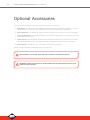
1
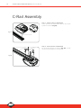
®
Controll-A-Door P Diamond
Sectional Door Opener SDO-2v2
Instruction Manual
Technical Document
Installation Manual
1.01
v
04 June 2012
English
N1854
Part # 79073 (Manual)
B&D Doors is a division of B&D Australia Pty Ltd
ABN 25 010 473 971
www.bnd.com.au
2
Controll-A-Door ® P Diamond SDO-2v2 Instruction Manual
Controll-A-Door® P Diamond
Sectional Door Opener SDO-2v2
03
Battery Back Up Installation
26
Risk Assessment
04
How To Use Your Opener
27
Default Settings & Specifications
05
Transmitter
27
06
Transmitter Battery
28
Operating Controls
07
Locking
28
Kit Contents
09
Manual Release
28
10
Power Failure
28
C-Rail Assembly
10
Safety Beam
29
Determine Door Type
11
Auto-Close
29
Mounting - Track Type Door
12
Courtesy Light
29
Mounting - Non-Track Type Door
13
Auxiliary Output
29
Mounting Door Bracket & Arms
14
Vacation Mode
29
Programming the Opener
15
Pet Mode
29
Setting Speed and Limits
15
Maintenance
30
Testing Safety Obstruction Force
17
Troubleshooting Guide
31
Coding Transmitters
18
Parameters
32
Door
18
Parts List
33
Courtesy Light
18
Warranty
34
Vacation Mode
19
Optional Accessories
36
Auxiliary Output
19
Pet (Pedestrian) Mode
20
Erasing Transmitter Codes
20
Mounting Wall Transmitter
20
Safety Rules
About Your Opener
Installation
Wireless Safety Beam Installation
21
Wired Safety Beam Installation
24
Accessories
25
Terminal Block
25
Remote Aerial
25
Controll-A-Door ® P Diamond SDO-2v2 Instruction Manual
Safety Rules
Please read these important safety rules
These safety alert symbols indicate a personal safety or property damage
instruction exists. READ THESE INSTRUCTIONS CAREFULLY.
This automatic garage door opener is designed and tested to offer safe
service provided it is installed and operated in strict accordance with the
following safety rules. Failure to comply with the following instructions may
result in death, serious personal injury or property damage.
CAUTION: If your garage has no pedestrian entrance
door, an emergency access device should be installed.
This accessory allows manual operation of the garage
door from outside in case of power failure.
Position the Garage Door Opener so that the power plug
is accessible when inserted into the power outlet (EN
60335-1).
This opener should be installed in accordance with relevant
Australian Standards.
Do not allow children to play with door controls.
Keep transmitters away from children.
Watch the moving door and keep people away until the
door is completely opened or closed.
Activate the opener only when the garage door is in full
view, free of obstructions and with the opener properly
adjusted.
Keep the garage door balanced. Sticking or binding
doors must be repaired. Garage doors, door springs,
brackets and their hardware are under extreme tension and
can cause serious personal injury. Do not attempt any garage
door adjustment. Do not use if repair or adjustment is needed.
Call for professional garage door service.
Install the optional wall transmitter in a location where the
garage door is visible, but out of the reach of children at
a height of at least 1.5m.
Disconnect electric power to the garage door opener
before removing covers.
Doors requiring over 400N of force to move must have
Safety Beams fitted.
Do not wear rings, watches or loose clothing while
installing or servicing a garage door opener.
This opener is not suitable for commercial, industrial
or common entry applications.
To avoid serious personal injury from entanglement,
remove all unnecessary ropes or chains and disable
any equipment such as locks which are not needed for
powered operation.
Installation and wiring must be in compliance with
your local building and electrical codes. Connect
the power cord only to properly earthed mains. If an
extension lead must be used, make sure it is a 3-core lead
and approved to 7 amp capacity.
If the power cord is damaged, it must be replaced
by the manufacturer, its service agent or a similarly
qualified person in order to avoid a hazard.
When using optional Auto-Close mode, a Safety
Beam (Part No 062734) must be fitted correctly
and tested at regular intervals. Extreme caution is
recommended when using Auto-Close mode. All safety
rules must be followed.
This opener is a plug in domestic appliance and is
designed for indoor use only. It must be installed in
a dry position that is protected from the weather.
The opener is not intended for use by young children
or infirm persons without supervision.
WARNING! It is vital for the safety of
persons to follow all instructions. Save
these instructions.
B&D Doors to the extent that such may be lawfully excluded hereby expressly disclaims all conditions or warranties, statutory or otherwise which may be implied by laws as
conditions or warranties of purchase of a B&D Garage Door Opener. B&D Doors hereby further expressly excludes all or any liability for any injury, damage, cost, expense or claim
whatsoever suffered by any person as a result whether directly or indirectly from failure to install the B&D Garage Door Opener in accordance with these installation instructions.
© Copyright 2012 B&D Doors
Diamond PD Power Drive : Instruction Manual
3
4
Controll-A-Door ® P Diamond SDO-2v2 Instruction Manual
Risk Assessment
Please refer to the risk assessment table below and ensure all the necessary controls are in place.
Installation Risk Assessment
Hazard
Control
Muscular strain from incorrect lifting
of opener
•
Practice correct lifting techniques (carton weighs 9 kg)
Muscular strain from incorrect lifting
of door
•
Practice correct lifting techniques when required to lift the door as per
installation instructions
Entanglement in operating Opener
•
Never plug in and operate prior to installation
Uncontrolled spring tension release
•
•
•
Follow the installation instructions
Ensure the U-bolt on the opposite end to the motor is tight
Do not conduct any door repairs or maintenance (contact professional for
all door servicing)
Fall from ladder
•
•
•
Ensure ladder is the correct type for job
Ensure ladder is on flat ground
Ensure user has 3 points of contact while on ladder
Crush injury from unsecured door
•
Place a 2 metre exclusion zone around area under the door while it is
unsecured
Do not move under door while on door support (or ladder)
Follow the installation instructions
Fit door support (or ladder) snugly under door before removing U-bolt
and bracket
Ensure door support (or ladder) is on flat ground
•
•
•
•
Testing and Operation Risk Assessment
Hazard
Control
Entrapment under operating door
•
•
•
•
•
Keep children clear of operating door
Ensure the garage door is in good working order
Correctly set the Safety Obstruction Force
Install Photo Electric Beams (recommended)
Do not operate door when persons are near the door
Entanglement in moving door
•
•
Fit locking bar covers
Keep hands and loose clothing clear of door and guides at all times
Entanglement in operating Opener
•
Never plug in and operate prior to installation
Electrocution
•
•
•
•
Place opener in protected area so that it does not get wet
Do not spray with water
Do not open the protective covers
Do not operate opener if cable is damaged
Controll-A-Door ® P Diamond SDO-2v2 Instruction Manual
Default Settings & Specifications
Factory default settings
Default
Step
Minimum
Maximum
Maximum opener run time
60 seconds
-
-
-
Courtesy light time
4 minutes (approx.)
-
-
-
Obstruction force margin
2
1
0
14
Auto-Close time
30 seconds
-
-
-
Technical specifications
Power supply
230V - 240Va.c. 50Hz
Transformer rating
24Vd.c.
Standby power
2.2 Watts
Motor power
100 Watts
Motor type
24Vd.c. permanent magnet
Shuttle travel distance in the C-Rail
2.7m approx. (standard)
Maximum shuttle travel distance in the C-Rail
3.750 m (with one extension)
Maximum door opening:
Width:
Height:
Weight:
5500mm (16.5m2)
3000mm
100kg
Minimum headroom
30mm
Short term peak force
1000N (100kg) with Chain
800N (80kg) with Timing Belt
Lift force
600N (60kg) with Chain
500N (50kg) with Timing Belt
Nominal force
150N (15kg)
Receiver type
UHF Multi-frequency FM Receiver
Receiver code storage capacity
14 X 4 button Transmitter Codes
Transmitter frequency
UHF Multi-frequency FM Transmitter
Coding type
Code Hopping
Number of code combinations
Over 4.29 billion random codes
Code generation
Non-linear encryption algorithm
Transmitter battery
CR2032 (3 Volts)
Courtesy light
LED (Light Emitting Diodes)
Controller fuse
10A slow blow
*The actual travel of the door depends on configuration of the connecting arms.
Note: Intermittent operations may occur in areas which experience very strong winds. The strong wind puts extra pressure
on the door and tracks which may in turn intermittently trigger the safety obstruction detection system.
© Copyright 2012 B&D Doors
Diamond PD Power Drive : Instruction Manual
5
6
Controll-A-Door ® P Diamond SDO-2v2 Instruction Manual
About Your B&D Opener
Thank you for choosing a Controll-A-Door® P Diamond
automatic garage door opener, designed and developed in
Australia by B&D Doors.
The technically advanced construction of this opener
ensures you enjoy the following benefits:
Warranty
Five (5) year/10,000 cycles full parts and labour warranty
on motor, electronics and mechanical components of
the opener when installed by an Approved B&D Dealer
(conditions such as annual garage door servicing apply).
Tri-Tran Frequency Hopping Technology
Every time a transmitter is used, it simultaneously sends a
signal over three different frequencies, reducing the chance
of interference from other radio frequency sources.
Code Hopping Technology
Every time a transmitter is used a new security code
is generated from over 4.29 billion possible code
combinations. This greatly enhances the security of the
system and makes “code grabbing” a thing of the past!
Multi-Channel Transmitter
Multi-channel transmitters allow you to operate other
devices such as an adjoining garage door or automated
gate from the same handy unit.
Safety Reversing System
The automatic safety reverse system significantly reduces
the risk of death or serious injury if trapped by a closing door.
The safety reverse force can be adjusted for environmental
conditions such as windy areas.
LED Courtesy Light
Using the latest Light Emitting Diode (LED) technology, the
opener features two light modules These modules produce
a brilliant white light that illuminates the garage upon
activation.
The LED courtesy light automatically switches on for
approximately four (4) minutes (time programmable)
when operating the door. This can also be programmed to
turn on and off from a transmitter.
Battery Back Up
Optional Battery Backup power is available.
Memory Retention
In case of a power failure the opener does not lose the
transmitter codes or limit settings.
Soft Start/Soft Stop
The opener eases into and out of each cycle making
for smoother and quieter operation, as well as reducing
wear and tear on the door and opener.
Manual Release
The manual release handle allows the door to be
operated by hand in the event of a power failure.
Self Locking
There is no need to manually lock your garage door, as
the opener ‘positively’ locks the door when closed.
Periodic Maintenance Indicator
Opener will flash and beep after certain number of
cycles to indicate the door requires servicing. Contact
your dealer/installer for service.
Service Fault Indicator
Flashing LEDs on the control panel easily identify
operational problems or service requirements.
Dynamic Door Profiling
Changing door characteristics are automatically
compensated for and “learnt” with each operation of
the door.
Auto-Close
The Auto-Close option can be programmed to close
the door approximately 30 seconds after the door
has opened. PLEASE NOTE - Safety Beams must be
installed for this option to function.
External Aerial
An external aerial can be connected for sites where
radio reception is a problem.
Vacation Mode
A transmitter can be programmed to disable the
garage door opener radio receiver. This is ideal if the
door is to be left idle for prolonged periods.
Pet (Pedestrian) Mode
A transmitter can be programmed to open the door
partially to allow pets access to the garage. The door
opening height is adjustable via a handheld programmer.
Auxiliary Output
You can program a spare button on your transmitter to
operate this output, which can control items that use a
momentary close switching mechanism.
Controll-A-Door ® P Diamond SDO-2v2 Instruction Manual
Operating Controls
01. Terminal Block.
V+ is used to power devices such as Wireless Safety Beam, external receiver etc.
EB1 input is used to connect to Safety Beam.
0V (Input) is a 0 volt connection for Safety Beam, external receiver, osc, aux etc.
EB2 input is used to connect to second Safety Beam..
0V (Input) is a 0 volt connection for Safety Beam, external receiver, osc, aux etc.
O/S/C is used for the connection of a wired switch (momentary contact). This switch can then be used to open, stop
or close the door. Install the wall switch in a location where the switch is out of reach of children and the garage door
is visible.
AUX This function allows the opener to operate an alarm system via the garage door remote control.
02. OPERATE button (Blue) is used during installation to test the open, stop and close cycles for the opener. The opener
has to be initialised by the LIMIT SET button to make the OPERATE button operable.
03. SERVICE LED (Yellow) indicates when the opener requires service or repairs.
04. LIMIT SET button (Blue) is used during installation, together with the PLUS (+) and MINUS (-) buttons, to set the door
limit positions.
05. FORCE MARGIN SET button. The obstruction force margin is set automatically during installation. The margin can
be adjusted manually using the FORCE MARGIN SET button (White). Holding the FORCE MARGIN SET button and
pressing PLUS (+) or MINUS (-) buttons will increase or decrease the amount of force. The FORCE MARGIN SET button
should only be used if environmental factors, such as high winds, affect the door’s operation.
06. CODE SET LED (Red) flashes when a transmitter button is stored.
07. MINUS (-) button (Red) is used during installation to set the close limit position. Pressing and holding this button will
move the door in the close direction. Movement stops when the button is released. This button is also used for storing
or erasing the transmitter button you wish to use to command the door to open, stop or close.
NOTE: The safety obstruction system is inoperable whenever the MINUS (-) button is used to move the door.
08. CLOSE LIMIT LED (Red) is used during installation to help set the close limit position. It also illuminates and flashes as
the door closes, and remains on when the close limit position has been reached.
09. PLUS (+) button (Green) is used during installation to help set the open limit position. Pressing and holding this button
will move the door in the open direction. Movement stops when the button is released.
NOTE: The safety obstruction system is inoperable whenever the PLUS (+) button is used to move the door.
10. OPEN LIMIT LED (Green) is used during installation to help set the open limit position. It also illuminates and flashes
as the door opens, and remains on when the open limit position has been reached.
11. AUTO CLOSE JUMPER fit the shunt on both pins to enable Safety Beam triggered auto close
12. PROG INPUT is used to connect the Automatic Technology Handheld Programmer ‘PG-3’ for editing control and
receiver functions, accessing diagnostic tools, and activating special features and operating modes.
13. SBCO-2 Battery Charger connector to attach a Battery Back Up kit.
14. 10 Amp fuse to protect the electronic circuit board.
© Copyright 2012 B&D Doors
Diamond PD Power Drive : Instruction Manual
7
Controll-A-Door ® P Diamond SDO-2v2 Instruction Manual
8
14
13
Fig. 01
01
12
02
11
03
04
10
09
05
06
08
07
Controll-A-Door ® P Diamond SDO-2v2 Instruction Manual
9
Kit Contents
Powerhead Unit (Fig. 02)
1 x Controll-A-Door® P Diamond powerhead
1 x Transmitter pack
(Pack includes two keyring transmitters and batteries)
1 x Wall mount transmitter with battery
2 x Door attachment arms
1 x Accessory and hardware pack
1 x Installation Manual
Fig. 02
PLUS
Single Piece C-Rail with Pre-Assembled Chain
(Fig. 03)
NOTE: Chain in one piece rail has been tensioned by the
factory. Do not adjust the tension of the chain.
Fig. 03
IMPORTANT NOTE: If a modification to the length of the
track is required, the adjustment must be made from the
powerhead end only.
OR
Single Piece C-Rail with
Pre-Assembled Timing Belt (Fig. 04)
Note: timing belt in one piece rail has been tensioned by
the factory. Do not adjust the tension of the timing belt.
IMPORTANT NOTE: If modification to the track length is
required, adjustment must be made only from powerhead
end.
Fig. 04
© Copyright 2012 B&D Doors
Diamond PD Power Drive : Instruction Manual
Controll-A-Door ® P Diamond SDO-2v2 Instruction Manual
10
C-Rail Assembly
Step 1 - Attach C-Rail to Powerhead
Shaft
Locate and insert the powerhead’s shaft into the C-Rail’s
sprocket as shown in (Fig. 05).
Fig. 05
Locate shaft into sprocket
ck
Tra
Fig.06
2)
t (x
cke
bra
w
cre 10
es
ang M4 X
fl
x
’
He tite ‘S
tap
Step 2 - Secure C-Rail to Powerhead
Fix the two track brackets as shown in (Fig. 06). Fix with
the four screws supplied in accessory pack.
Controll-A-Door ® P Diamond SDO-2v2 Instruction Manual
11
Determine the Door Type
Step 3 - Determine the Door Type
Proceed from Step 5
Determine which type of garage door you have as illustrated
in (Fig. 07) to (Fig. 09).
For a sectional (panel) door on tracks (Fig. 07)
proceed with the installation from Step 4.
Track
Fig. 07
Door
Sectional door with track
For a one piece door on tracks (Fig. 08)
proceed with the installation from Step 4.
Proceed from Step 5
Track
Fig. 08
Door
One piece door with track
For a one piece door without tracks (on springs) (Fig. 09)
proceed with the installation from Step 8 (page 13).
Proceed from Step 8 on page 13
Door
Fig. 09
One piece door without track
© Copyright 2012 B&D Doors
Diamond PD Power Drive : Instruction Manual
Controll-A-Door ® P Diamond SDO-2v2 Instruction Manual
12
Mounting on a Track Type Door
Step 4 - Determine Bracket Position
a.
Level
Level
Track
Track
Fig. 10
b.
c.
Door
Door
Open the door and find the highest point of travel of
the top door panel.
Using a level, transfer this height to the wall above the
door (Fig. 10) and mark a line 60mm above it.
Determine the centre point on the wall above and on
top of the door. Then draw two (2) lines extending
21.5mm from each side of the centre point. (Fig. 11)
Step 5 - Mounting the Wall Bracket
a.
b.
c.
Fig. 11
Centre the bracket over the intersection of these two
lines. Mark centres for at least two holes (Fig. 11).
•
Ensure a solid mounting point is behind
these holes.
Drill holes into the wall with an appropriate sized bit.
Secure bracket to the wall using:
IF CONCRETE OR BRICK - 8mm or 5/6 loxins or
dynabolts.
IF TIMBER - wood screw #20 or equivalent
(minimum 50mm long).
WARNING: Make sure concrete, brick wall
or timber lintels are solid and sound so as to
form a secure mounting platform.
Drilled holes
Step 6 - Attach the C-Rail to the Wall Bracket
a.
b.
Step 7 - Securing the Powerhead to the Ceiling
Fig. 12
a.
b.
c.
d.
e.
Structural member
Fig. 13
Attach the C-Rail assembly to the wall bracket with the
90mm long clevis pin and secure with the supplied
snap pin (Fig. 12).
Leave the powerhead in its packing box for protection
during installation.
Raise the powerhead from the packing box and
support it in the horizontal position with a step ladder.
Open the garage door. Rest the opener on the open
door and use a scrap piece of wood to bring it to
horizontal level.
Line up the track perpendicular to the wall.
Secure the perforated angle (not supplied) to the
ceiling above where powerhead’s mounting holes will
be once fully installed. A representative mounting is
shown (Fig. 13).
Connect the powerhead to the ceiling mounted
perforated angle with M8x20mm screws and nuts.
Strips should not extend more than 18mm below
centre of powerhead mounting holes (Fig. 13).
For an alternative mounting option, go to Step 11.1
WARNING: The opener must be securely
fastened to structural supports, otherwise
opener failure may ensue causing serious
personal injury and/or property damage.
Controll-A-Door ® P Diamond SDO-2v2 Instruction Manual
13
Mounting on a Non-Track Type Door
WARNING: Make sure concrete, brick wall
or timber lintels are solid and sound so as to
form a secure mounting platform.
Centre of door
Fig. 14
Step 8 - Determine the Door’s Centre
a.
b.
Find the centre of the door and mark this location both
above the door and on top of the door.
Draw two lines 21.5mm either side of this (Fig. 14).
Step 9 - Prepositioning the Opener
a.
b.
c.
Raise the door to open position.
Rest the opener on the top edge of the door with end
of the C-Rail against the wall (Fig. 15).
Support the powerhead level with the lowest point of
the open door (Fig. 15).
NOTE: Do not slide C-Rail along the face of the door.
Step 10 - Mounting the C-Rail
a.
b.
c.
d.
e.
f.
g.
h.
Close the door slowly. The C-Rail will be elevated by
the top edge of the door as it moves.
Stop the door when it is at its highest point of travel.
Allow 25mm additional height for clearance between
the door and the track (Fig. 16).
Support the C-Rail in this position and close the door
The height determined in Step 11(b) will be the height
at which to mount the wall bracket.
Centre the bracket along the line determined in Step 9.
Using the bracket as a template, mark a minimum
of two holes and drill with appropriate size bit. For a
more secure fitting, the wall bracket can be anchored
using more than two holes.
Secure the bracket to the wall using:
IF CONCRETE OR BRICK - 8mm or 5/6 loxins or
dynabolts.
IF TIMBER - wood screw #20 or equivalent
(minimum 50mm long).
Attach the wall bracket to the C-Rail with the 90mm
long clevis pin (Fig. 17) and secure by a snap pin.
Fig. 15
Step
Ladder
C rail
Fig. 16
Highest point
of door travel
Door
Step
Ladder
Step 11 - Securing the Powerhead to the Ceiling
a.
b.
Secure the perforated angle (not supplied) to the
ceiling above where powerhead’s mounting holes will
be. See (Fig.13) for a representative mounting.
Connect the powerhead to the ceiling mounted
perforated angle with M8x20mm screws and nuts.
Strips should not extend more than 18mm below
centre of powerhead mounting holes (Fig. 13).
Fig. 17
WARNING: The opener must be securely
fastened to structural supports, otherwise
opener failure may ensue causing serious
personal injury and/or property damage.
© Copyright 2012 B&D Doors
Diamond PD Power Drive : Instruction Manual
Controll-A-Door ® P Diamond SDO-2v2 Instruction Manual
14
Mounting Door Bracket and Arms
Drill hole at centre of track
(recommended bolt size
M6 or M8)
Fig. 18
Ceiling
The height of bolt
head must not
exceed 6 mm
Aluminium rail
Step 11.1 - Alternative Mounting Option
The opener can be fastened to the roof by driving a bolt
through the C-Rail into a structural timber support. The bolt
head’s height must not exceed 6mm (Fig. 18).
Step 12 - Mounting Door Bracket
The door bracket comes in two parts. The bottom plate
with two mounting holes is used on its own for one piece
doors. For sectional doors, the top plate is placed over the
bottom plate and is fixed with four (4) screws (Fig. 19).
Shuttle assembly
a.
b.
Fig. 19
Mount the door bracket, or bracket assembly, on the
door’s centre line one-third down the top panel (Fig.
19) using M6 or equivalent screws (not supplied),
STEEL DOORS ONLY: Bracket can be welded in
place.
NOTE: If in doubt about the door’s strength,
reinforcement may be added to the door’s
frame where necessary. Door damage may
occur if the bracket is installed on a panel
with insufficient strength. The opener’s
warranty does not cover damage caused to
the door and/or door panels.
Step 13 - Attaching the Arms
Fig. 20
A
FOR SECTIONAL AND ONE PIECE DOORS WITH TRACK:
a. Assemble the bent and straight arms with bolts
and nuts supplied in the accessory pack (Fig. 20).
Always use both bent and straight arms.
b. Connect the assembled arm to the bracket and the
disengaged trolley with clevis and snap pins. The
angle “A” must be more than 10° (Fig. 20).
WARNING: Connecting the bent arm other
way around may damage the door.
FOR ONE PIECE DOORS WITHOUT TRACK
a. Assemble the bent and straight arms as shown in (Fig.
21) with bolts and nuts supplied in the accessory
pack. Always use both the bent and straight arms.
b. Connect the assembled arm to the bracket and the
disengaged trolley with clevis and snap pins.
c. If installing on a door with a bad wave action,
lengthening the arm will assist in reducing this effect.
Fig. 21
IMPORTANT NOTE - If the manual release
handle is more than 1.8 metres from floor level
when the opener is installed, extend the handle
to a height less than 1.8 metres.
Controll-A-Door ® P Diamond SDO-2v2 Instruction Manual
15
Setting Speed and Limits
Step 14 - Setting Speed Mode
The default speed of the opener has been set to suit the
majority of applications. However, there are 3 speed modes
available if required:1.
2.
3.
Slow - to suit one piece door without tracks
Medium ( default ) - suits majority of applications
Fast - to suit some sectional applications
Fig. 22
The speed settings can only be changed before setting
the travel limits. If the opener speed needs to be changed
please complete the steps below. If medium (default) mode
is appropriate skip straight to step 15.1 setting travel limits.
Pressing the operate button will cycle through all three
speed modes. To change the speed setting:a.
b.
c.
d.
e.
Engage the C-Rail’s trolley (attached to the door via
the arms) with the chain index by moving the door.
If the trolley does not “click” firmly onto the chain
index, ensure that the manual release cord is not in
the disengaged position by pulling it backwards.
Turn on the power to the opener. The Close Limit LED
will be flashing.
Remove the button cover with a blade screwdriver
(Fig.22).
Press operate button once, twice or three time to
select slow, medium or fast speed mode.
Door Opener
Speed Mode
Open
LED
(Green)
Close
LED
(Red)
Beeper
Medium ( Default )
On
On
2 beeps
Fast
On
Off
3 beeps
Slow
Off
On
1 beep
© Copyright 2012 B&D Doors
Diamond PD Power Drive : Instruction Manual
16
Controll-A-Door ® P Diamond SDO-2v2 Instruction Manual
Setting Travel Limits
IMPORTANT NOTE: The OPERATE button will
not function until the open and close limit
positions are set.
NOTE: The door and shuttle must be engaged
into the chain index. The door should be open
approximately half way.
Fig. 23
Step 15.1 - Setting Limits Positions
a.
b.
c.
d.
e.
Remove the controls cover to access the controls
panel as shown in (Fig. 23). Replace it when setup
is completed.
Press and hold the MINUS (-) button to start the door
closing. Release the button once you have reached
your desired closed limit position (Fig 24).
Press the LIMIT SET button. This action will store the
close limit position into memory.
Press and hold the PLUS (+) button to start the door
opening. Release the button once you have reached
your desired open limit position.
Read the WARNING below.
IMPORTANT WARNING: The garage door will
automatically close, open and close again once
the LIMIT SET button is pressed. Ensure there
are no persons or objects in the door’s path
before pressing the LIMIT SET button.
Fig. 24
f.
Press the LIMIT SET button to store into memory the
open limit position. The door will now automatically
close to its limit position then fully open to calculate the
Safety Obstruction Forces
BE AWARE OF THE ABOVE WARNING.
The opener can now be operated via the OPERATE button.
Step 15.2 - Resetting Door Limit Positions
Fig. 25
To enter new limit positions the existing settings must be
deleted as follows:
a. Press and hold the LIMIT SET button (Fig. 25) for six
(6) seconds, until you hear three beeps and the CLOSE
LIMIT LED starts to flash.
b. Release the button.
c. Follow Step 15.1 to set new limit positions.
Controll-A-Door ® P Diamond SDO-2v2 Instruction Manual
17
Testing Safety Obstruction Force
CAUTION: Take care when testing the safety
obstruction force. Failure to follow this
warning can result in serious personal injury
and/or property damage.
16.1 Test the Close Cycle
a.
b.
c.
d.
Press the OPERATE button to open the door (Fig. 26).
Place a piece of timber approximately 40mm high on
the floor directly under the door (Fig 27).
Press the OPERATE button to close door.
The door should strike the object and re-open.
Fig. 26
16.2 Testing the Open Cycle
a.
b.
c.
Press the OPERATE button to close the door (Fig. 26).
Press again to open the door.
When the door reaches approximately half way, firmly
grab the door’s bottom rail - the door should stop.
If the door does not reverse readily when closing, or stop
when opening, the force may be excessive and need
adjustment, refer to Step 16.4.
Fig. 27
IMPORTANT WARNING: If the door is closing
and is unable to re-open when obstructed,
discontinue use. Do not use a door with faulty
obstruction sensing. Repair fault and re-test
before using.
40mm
Adjusting Safety Obstruction Force
The safety obstruction force is calculated automatically
and normally does not require adjustment. The only time
the force may need to be adjusted is due to environmental
conditions, such as areas that are windy, dusty or have
extreme temperature changes that affect the operability
and movement of the door.
Step 16.4 - To Decrease Force Pressure
a.
b.
c.
WARNING: Doors requiring over 400N of force
to move must have Safety Beams fitted for safety.
Step 16.3 - To Increase Force Pressure
a.
b.
c.
d.
e.
Press and hold the FORCE MARGIN SET button (Fig
28).
While holding down the FORCE MARGIN SET button,
press the PLUS (+) button.
Each press will increase the force margin one step.
The OPEN LIMIT LED will flash each time the PLUS
(+) button is pressed to indicate an increase in force.
Test the force again as per Steps 16.1 and 16.2.
If the OPEN LIMIT LED flashes continuously when the
PLUS (+) button is being pressed, this indicates that
the maximum force setting has been reached.
d.
e.
Press and hold the FORCE MARGIN SET button
(Fig 26).
While holding down the FORCE MARGIN SET
button, press the MINUS (-) button.
Each press will decrease the force margin one
step. The CLOSE LIMIT LED will flash each time
the MINUS (-) button is pressed to indicate a
decrease in force.
Test the force again as per Steps 16.1 and 16.2.
If the CLOSE LIMIT LED flashes continuously
when the MINUS (-) button is being pressed,
this indicates that the minimum force setting has
been reached.
Step 16.5 - To Recall Factory Set Force
a.
b.
Holding down the FORCE MARGIN SET button
and the LIMIT SET button for two seconds.
Release both buttons. The default setting should
now be recalled.
© Copyright 2012 B&D Doors
Diamond PD Power Drive : Instruction Manual
18
Controll-A-Door ® P Diamond SDO-2v2 Instruction Manual
Coding Transmitters
Step 17.1 - Storing the Transmitter Code
The opener can only operate from transmitters that have
been programmed into its receiver. The receiver needs to
learn the codes of any transmitter that will be used with the
operator. Up to fourteen (14) codes can be stored in the
receiver’s memory.
Fig. 28
Press CODE SET
button once
a.
b.
Select one of the four
buttons you wish to use
to control the door
c.
d.
e.
Fig. 29
Press CODE SET
button twice
Ensure that the battery is inserted into the
transmitter.
Press the CODE SET button and release. The
CODE SET LED will illuminate to indicate the
opener is in Code Learn mode. If a valid code is
not stored within 15 seconds the opener will exit
Code Learn (Fig. 28).
Press the transmitter button (one of four) that you want
to control the door. The CODE SET LED will begin to
flash.
Press the same transmitter button again. The CODE
SET LED will illuminate for one second and then go
out.
The transmitter is now coded to operate the door - press
the button to test.
Step 17.2 - Setting the Transmitter to Operate the
Courtesy Light
Although the courtesy light comes on with each operation of
the opener, it may also be controlled by a transmitter without
operating the door.
Select one of the
four buttons (not
programmed yet ) you
wish to use to control
the courtesy light
a.
b.
c.
d.
Press the CODE SET button twice. The CODE SET
LED will illuminate and the courtesy light will turn on to
indicate that the light code learning is active (Fig. 29).
Choose a transmitter button not already coded into the
receiver. Press this button and the CODE SET LED will
begin to flash.
Press the same transmitter button again. The CODE
SET LED will illuminate for one second and then go
out.
The transmitter is now coded to operate the light - press
the button to test.
Controll-A-Door ® P Diamond SDO-2v2 Instruction Manual
19
Coding Transmitters
Step 17.3 - Setting the Transmitter to Operate
Vacation Mode
The opener can be programmed into a “Vacation Mode”
where the opener will not respond to any transmitter except
one preprogrammed unit.
a.
b.
c.
d.
e.
Press CODE SET button three times. The CODE SET
LED will illuminate and the courtesy light will flash
slowly (once every two seconds) to indicate Vacation
learning mode is active. (Fig. 30)
Choose a transmitter button not already coded into the
receiver. Press this button and the CODE SET LED will
begin to flash.
Press the same transmitter button again. The CODE
SET LED will illuminate for one second and then go out,
and the courtesy light will also switch off. This indicates
the code has been stored (Fig. 30).
To activate Vacation Mode, close the garage door and
press the coded button transmitter for 5 seconds.
The CODE SET LED will illuminate to indicate that the
opener is in Vacation Mode.
To exit Vacation Mode press the transmitter button
momentarily until the CODE SET LED turns off.
Press CODE SET
button three times
Fig. 30
Select one of the
four buttons (not
programmed yet ) you
wish to use to control
the Vacation Mode
Press CODE SET
button four times
Step 17.4 - Setting the Transmitter to Operate the
Auxiliary Output
It is possible to operate other devices (e.g. alarm systems)
using one of the spare buttons of a multi-channel transmitter
coded into the Auxiliary Output feature.
a.
b.
c.
Press CODE SET button four times. The CODE SET
LED will illuminate and the courtesy light will flash
quickly (twice per second) to indicate that learning
mode for the Auxiliary Output is active.
Choose a transmitter button not already coded into the
receiver. Press this button and the CODE SET LED will
begin to flash.
Press the same transmitter button again. The CODE
SET LED will illuminate for one second and then go out,
and the courtesy light will also switch off. This indicates
the code has been stored (Fig. 31).
Fig. 31
Select one of the
four buttons (not
programmed yet ) you
wish to use to control
the Auxiliary out put
© Copyright 2012 B&D Doors
Diamond PD Power Drive : Instruction Manual
20
Controll-A-Door ® P Diamond SDO-2v2 Instruction Manual
Coding Transmitters
Step 17.5 - Setting the Transmitter to Operate Pet
(Pedestrian) Mode
The opener can be programmed into a “Pet Mode” where the
door opens partially to allow pets to enter/exit the garage:
Fig. 32
Press CODE SET
button five times
a.
b.
Select one of the
four buttons (not
programmed yet ) you
wish to use to control
the door for pet position
c.
Press the CODE SET button five times, the CODE SET
LED will illuminate and the courtesy light will flash
quickly (twice per second) to indicate learning mode for
Pet Mode is active.
Choose a transmitter button not already coded into the
receiver. Press this button and the CODE SET LED will
begin to flash.
Press the same transmitter button again. The CODE
SET LED will illuminate for one second and then go out,
and the courtesy light will also switch off. This indicates
the code has been stored. This indicates the code has
been stored (Fig. 32).
Step 17.6 - To Erase Programmed Codes
If the CODE SET button is pressed and held for 6 seconds the
CODE SET LED will blink rapidly for one second to indicate
that all programmed codes have been erased. (Fig. 33)
Fig. 33
Step 18 - Installation of the Wall Mounted
Transmitter
a.
Fig. 34
b.
c.
Mount the transmitter in a convenient location, yet out
of reach of children and at least 1.5m off the ground
(Fig. 34).
Make sure the door is visible from this location.
To set the transmitter codes refer to Step 17.1.
Controll-A-Door ® P Diamond SDO-2v2 Instruction Manual
21
Wireless Safety Beams Installation
WARNING: Safety beams must be installed
if the closing force at the bottom edge of the
door exceeds 400N (40kg force). This is in
compliance with AS/NZS 60335-2-95
Step 20.1 -Wireless Photo Electric (PE) Beams
(optional)
A photo electric (PE) Beams extends across the door
opening. This Safety Beam is designed to detect an
obstruction while the door is closing and to send a signal
to the door opener to reverse or stop the door movement.
The wireless Safety Beam consists of:
1. Base Station Assembly
2. Receiver Assembly
3. Transmitter Assembly
4. Safety Beams Mounting Kit
5. Base Station Mounting Kit
Fig. 38
Receiver
Transmitter
Base Station
The base station connects to the opener with the cable
supplied. The receiver and base station has a wireless
link. The receiver must be coded into the base station
before fixing it to its position. Four C-type batteries are
supplied in the kit for receiver and the transmitter.
Fig. 39
Step 20.2 -Installation
Remove the front cover from receiver, transmitter and the
base station. To remove the front cover:
Hold the box in both hands and push in the front cover by
applying the pressure at shown points in Fig.39
Pull the front cover apart
Apply pressure here
Pull covers apart
WHITE
CODE
RED
YELLOW
SDO-2v2
terminal block
NOT IN USE
Fig. 40
RESET
0V
EB1
V+
WHITE
YELLOW
LED
RED
© Copyright 2012 B&D Doors
Diamond PD Power Drive : Instruction Manual
22
Controll-A-Door ® P Diamond SDO-2v2 Instruction Manual
Wireless Safety Beams Installation
Step 20.3 -Connecting The Base Station To The
Opener
a.
b.
c.
Fig. 41
+
RESET
Fig. 42
+
Receiver
LED
Connect WHITE wire from base station to 0V on the
terminal block of the opener
Connect RED wire from base station to V+ on the
terminal block of the opener.
Connect YELLOW wire from the base station to
EB1,EB2 or EB3 on the terminal block of the opener.
See Fig. 40. Please note the exact position of these
terminals will vary by opener type.
Step 20.4 -Coding The Receiver Into The Base
Station
Base station can only hold one receiver in the memory.
Coding a new receiver will replace the old one from the base
station memory.
a. Power up the opener, the LED on the base station will
light up and remains on constantly Fig. 40.
b. Insert two C-type batteries in the receiver. The LED on
the receiver will also lightup and remains on constantly
Fig. 41.
c. Press and hold CODE push button on the base station.
Keep holding until step.e.
d. While holding CODE push button, press and release
RESET button on the base station. The LED on the
base station will start flashing.
e. Press RESET button on the receiver for two (2)
seconds, the LED on the base station will start to flash
faster. Pause for two (2) seconds, then press reset
button on the receiver again for two (2) seconds. The
LED on the base station will stop flashing.
f.
Release the CODE push button from the base station
and wait for the LED’s on the base station and on the
receiver to turn off.
g. The LED on the receiver will now start to blink.
h. put the covers back on the base station and receiver
and secure with the 4x #6 x 25 screws (black)
supplied. (Fig. 42)
Controll-A-Door ® P Diamond SDO-2v2 Instruction Manual
23
Wireless Safety Beams Installation
Step 20.5 -Fixing The Base Station To Wall/
Opener
The base station can be attached directly to a sectional
opener using the M8 bolt and nut supplied. The wire can be
fed through the top gromet of the opener (Fig. 43)
Fig. 43
Note: The bracket may also be rotated so the base station
hangs above the power head.
Step 20.6
Transmitter
a.
b.
c.
d.
e.
f.
-Installing
The
Receiver
And
Insert two C-type batteries in the transmitter (Fig.
44).
Attach the front cover on the transmitter and secure it
with four self tapping #6 x 25 screws (supplied).
Attach the mounting bracket to the adjustment bracket
with one pan head screw M5 x 10. (Fig. 45).
Place the pe bracket on the back of the receiver/
transmitter and secure it with four (M3x5) screws.
Attach the receiver/transmitter to the adjustment
bracket with one pan head screw M5 x 10.
Mount the receiver to the side of the door closest to
the base station and transmitter on the other side in
line with receiver. The mounting surface should be
rigid. In domestic applications ATA recommends the
transmitter and receiver are placed in line of sight,
with the beam 100mm above ground level (as per
AS60335). This can be achieved by ensuring the
bottom of the receiver and transmitter are 65mm
above ground level. They should also be placed as
close as possible to the door opening (Fig. 46).In
industrial applications it is recommended that multiple
Safety Beams are fitted.
+
+
RESET
Fig. 44
LED
Transmitter
Mounting Bracket
t
ke
PE
ac
Br
Fig. 45
Step 20.7 -Optical Alignment
a.
b.
c.
Make horizontal and/or vertical adjustment on the
transmitter until the red LED on the receiver stays on,
this indicates alignment.
Make horizontal and/or vertical adjustment on the
receiver until the red LED on the transmitter stays on,
this indicates alignment.
Setup the limits of the door opener as per instruction
manual.
t
cke
tin
un
Mo
ra
gB
WARNING: When using Safety Beams, the
doorway must be clear of all obstructions
and persons at all times. The location of the
beams and manner in which it is installed
might not give safety protection at all times.
Check to make sure that the height of the
beam and type used give maximum protection
possible.
Fig. 46
65mm
100mm
65mm
Floor Level
© Copyright 2012 B&D Doors
Diamond PD Power Drive : Instruction Manual
24
Controll-A-Door ® P Diamond SDO-2v2 Instruction Manual
Wired Safety Beams Installation
WARNING: Safety beams must be installed
if the closing force at the bottom edge of the
door exceeds 400N (40kg force). This is in
compliance with AS/NZS 60335-2-95
6
4
3
Step 19 - Safety Beams (optional)
Fig. 35
Safety Beams extend across the garage door opening. The
Safety Beam is designed to detect an obstruction while
the door is closing and to send a signal to the garage door
opener to reverse or stop the door movement. One or
two sets of Safety Beams can be connected to SDO-2v2
opener.
2
6
1
Step 19.1 - Fitting the Safety Beam
a.
b.
c.
d.
e.
Fig. 36
Attach the mounting bracket (4) to the adjustment
bracket (3) with the pan head screw (6) (supplied).
(Fig. 35)
Attach the bracket (2) to the Safety Beam transmitter
with four taptite screws (m3x5) and attach the other
side to the adjustment bracket (3) with the pan head
screw (6) . (Fig. 36)
Repeat steps a and b to assemble the Safety Beam
receiver.
Mount the receiver to one side of the door and
transmitter on the other side in line with receiver. The
mounting surface should be rigid. ATA recommends
the transmitter and receiver are placed in line of sight,
with the beam 100mm above ground level (as per
AS60335). They should also be placed as close as
possible to the door opening. Connect as per the wiring
diagram (Fig. 37).
Step 19.2 - Alignment
a.
b.
c.
Fig. 37
BLACK
BLACK
BLACK
RED
RED
RED
Power up the opener with the Safety Beam connected.
The green LED on the transmitter should turn ON to
indicate power is present.
If the receiver is connected to power and the red LED
is flashing while the green LED on the transmitter is on,
the transmitter and receiver are not aligned.
Make horizontal and/or vertical adjustment on the
transmitter and/or receiver until the red LED on the
receiver turns on, indicating alignment.
NOTE: The sensors need to be 100mm above
the floor level however, The exact position must
be chosen in such a manner that it suits the
application, the environmental conditions and
provides maximum safety protection.
BLACK
Note: Three wire Safety Beam is not compatible with SDO2v2 opener.
Controll-A-Door ® P Diamond SDO-2v2 Instruction Manual
25
Accessories
Terminal Block
A variety of wired accessory items can be connected to the
terminal block such as Safety Beams, electric key switch,
and more (Fig. 47).
Terminal connections from top down are as follows:
1. V+
2. EB1 (Safety Beam input)
3. 0V (0V for Safety Beam)
4. EB2 (Safety Beam input)
5. OSC (Open/Stop/Close trigger)
6. AUX OUT (Auxiliary output trigger)
Remote Aerial (Part No 062177)
Some sites cause poor radio reception. Particularly
problematic areas are those where there is a large amount
of metal, like an all steel garage, or an underground car
park with large masses of steel reinforced concrete. These
issues, and others, can create radio reception issues.
Poor radio reception will be noticed by a reduction in the
operating range of the transmitters.
V+
EB1
0V
EB2
0V
OSC
AUX
Fig. 47
You can evaluate whether fitting an external aerial will
benefit as follows:
•
test the maximum operating range of the transmitter
with the garage door closed; then
•
test the maximum operating range of the transmitter
with the garage door open.
If the range improves when the door is open you can install
a remote aerial kit to improve reception.
Mount the aerial to a suitable location on the outside of
the garage. Similar to a television aerial, the better the
mounting position the better the reception will be. Where
possible, mount the aerial as high as possible, away from
masses of metal and in a line of sight position to where you
normally use your transmitter.
© Copyright 2012 B&D Doors
Diamond PD Power Drive : Instruction Manual
Controll-A-Door ® P Diamond SDO-2v2 Instruction Manual
26
Battery Back Up Installation
Fig. 48
Battery Back Up (optional)
The opener has provision for a Battery Back Up kit
that allows continued operation of the door in the
absence of mains power.
Installation
1.
2.
3.
4.
5.
6.
Disconnect power to the opener.
Remove screws and swing open the cover (Fig
48).
Mount the PCB support with two screws item #
12. Secure the SBC0-2 Charger Board onto the
PCB support with three (3) screws item #14.
Feed the 2-wire battery harness item # 5 through
the grommet on the base plate and connect to
SBCO-2 battery charger board.
Feed charger harness from SBCO-2 battery
charger board to the control board and plug onto
the 5 pin connector marked “SBCO-2” on the
control board.
Mount Battery Backup and secure with item 11
and 13.
Warning: After the next step the opener
may become active (even when power
is off) due to a residual charge in the
batteries.
7. Connect item 5 and 10 together (Fig 48).
8. Reconnect power.
Testing Battery Back Up
1.
2.
Press either the OPERATE button or transmitter
to activate the opener.
Whilst the door is in motion disconnect mains
power - the opener should continue to operate.
Note: Wait for the door to complete its
travel before proceeding to the next step
3.
4.
Press either the OPERATE button or transmitter
to activate the opener.
Whilst the door is in motion re-connect power.
The door should complete the cycle as normal.
Troubleshooting
If door stops or moves very slowly under battery power,
then the batteries may have little to no charge.
To remedy this connect mains power and leave the
batteries to charge. The batteries may take 24 to 48
hours to reach their maximum charge capacity.
Controll-A-Door ® P Diamond SDO-2v2 Instruction Manual
27
How to use your opener
For maximum efficiency of your opener, your garage door
must be in good operating condition.
An annual service of your garage door by an Approved
Dealer is recommended.
CAUTION - Activate the opener only when
the door is in full view, free of obstructions
and with the opener properly adjusted. No one
should enter or leave the garage while the
door is in motion. Do not allow children to
play with or near the door.
Fig. 49
WARNING! This opener is a mains voltage
plug-in domestic appliance and there are no
user serviceable parts inside this opener.
Transmitter
•
•
•
•
To operate the opener, press the programmed
transmitter button until your door begins to move
(usually 2 seconds). Make sure you can see the door
when you use the transmitter.
If you are in a vehicle you should aim the transmitter
through your windscreen (Fig. 49).
Check that the door is fully closed before you drive
away.
If you press the transmitter whilst the door is moving
the door will stop. The next press of the transmitter will
move the door in the opposite direction.
The transmitter may also be programmed to operate the
following features (see Pages 18 to 20 for full details):
•
to turn the courtesy light on and off without operating
the door,
•
to activate the Auxiliary Output,
•
to put the door into “Pet Mode” where it opens partially
to allow pet access to the garage, and/or
•
to put the garage door opener into “Vacation Mode”
where it will not respond to any transmitters.
NOTE: Additional transmitters may be purchased at any
time.
© Copyright 2012 B&D Doors
Diamond PD Power Drive : Instruction Manual
28
Controll-A-Door ® P Diamond SDO-2v2 Instruction Manual
How To Use Your Opener
Removing the Battery From the Transmitter
(Battery Type: 3V Lithium Battery CR2032).
Use a non-metallic object (e.g. pen) to remove the battery.
(Fig. 50)
Inbuilt Locking Facility
Fig. 50
DO NOT lock your door when your opener is engaged as it
has inbuilt locking facility. With the opener engaged your
door will be locked whether the power is on or off.
Manual Door Operation
REPLACE BATTERY WITH CR2032 ONLY
CAUTION: when operating the manual release
while the door is open. The door may fall
rapidly due to weak or broken springs, or due
to being improperly balanced. (AS3350)
CAUTION! Do not disengage the opener to
manual operation with children/persons or
any objects including motor vehicles within
the doorway.
To disengage the opener from the door (preferably with
the door in the closed position), pull down on the string
handle on an angle towards the door. This will allow you to
manually open or close the door. To re-engage the opener
pull the string handle away from the door.
WARNING! When the opener is manually
disengaged, the door is no longer locked. To
lock the door manually, re-engage the opener
after the door is closed.
Power Failure
When there is a power failure, the opener will be unable to
automatically open or close your garage door. To use your
door whilst there is no power you will need to disengage the
opener and use the door manually – see Manual Operation
above.
Controll-A-Door ® P Diamond SDO-2v2 Instruction Manual
How To Use Your Opener
Safety Beam
A Safety Beam Kit (Part No 062734) may be fitted to this
opener.
•
When this option is fitted, the operation of this device
is such that if an object (i.e. car, child, etc.) blocks
the Safety Beam, then the garage door opener will not
close the door automatically.
•
If the Safety Beam is fitted but not operating correctly,
then the door once opened automatically, will not close
automatically. The door may be closed by reverting to
manual operation – see Manual Operation.
Auto-Close Option
To have the Auto-Close option functional you must also have
a Safety Beam (Part No 062734) fitted and functioning.
To enable the Auto-Close function, place the AUTO-CLS
jumper on both pins
When this option is selected the garage door opener will
attempt to close the door automatically 30 seconds after
opening.
If the Safety Beam is interrupted whilst the door is closing
(e.g. by a person walking through the doorway), the door
will reverse to the fully open position.
If the door does not close automatically, you may close the
door using the Manual Operation.
Courtesy Light
The Courtesy Light will illuminate for approximately four (4)
minutes each time the door is operated automatically.
Spare buttons of a multi-channel transmitters can be
programmed to turn the light on and off by remote control.
See Step 17.2 for more information.
Auxiliary Output
This function allows the opener to operate other devices
such as external lights or an alarm system.
To use this function, a spare button of a multi-channel
transmitter must be programmed to operate the Auxiliary
Output feature.
Vacation Mode
The radio receiver of the garage door opener can be
turned off to all but one transmitter via Vacation Mode.
Whilst in vacation mode the opener will not respond to
any transmitter.
To activate the Vacation Mode facility, see Step 17.3.
NOTE - program only one button to control “Vacation
Mode”. This will reduce the possibility of accidental
activation of this feature.
Pet (Pedestrian) Mode
A transmitter can be programmed to open the door
partially to allow pet access to the garage.
To activate Pet Mode press the transmitter button that
has been programmed for Pet Mode - the door will
open partially.
See Step 17.5 for more information.
Service
While the door opener does not require regular
servicing, to function correctly the door must be in
good operating condition. As a reminder the SDO2v2 has a built in maintenance counter. This counter
has a factory default of 3000 cycles, which is the
recommended service interval.
When this counter expires the yellow SERVICE LED will
light up and opener beep three times at the start of
each cycle. In addition the courtesy light will flash and
opener beep five times at the end of open cycle (when
the door is fully open).
These warning signals will self extinguish after 30
cycles. When this service counter is triggered it is
strongly recommended you contact your garage door
dealer to arrange a door service.
However, if you choose not to have your door serviced
the counter can be reset simply by pressing the LIMIT
SET button.
See Step 17.4 for more information.
© Copyright 2012 B&D Doors
Diamond PD Power Drive : Instruction Manual
29
30
Controll-A-Door ® P Diamond SDO-2v2 Instruction Manual
Maintenance
Maintenance
Whilst your opener does not require any periodic
maintenance, the door that it is fitted to, does. Your
garage door is a large, heavy, moving object and should
be tested regularly to ensure it is in good condition. A
poorly maintained door could cause fatal or serious
injuries or serious damage to property.
Yearly
B&D suggests that you contact your nearest Approved
Dealer to perform an annual door service.
CAUTION: Frequently examine door,
particularly cables, springs and mountings for
signs of wear, damage or imbalance. Do not
use if repair or adjustment is needed since
a fault in the installation or an incorrectly
balanced door may cause injury. (AS3350)
SDO-2v2 has a built in maintenance counter. From
factory this is loaded with 3000 cycles. When this
counter expires, the service yellow LED will lit , beeper
will sound three times at the start of open or close
cycle and the courtesy light will flash and beeper will
beep five times just after fully opening the door.
B&D suggests that you contact your nearest Approved
Dealer to perform an door service.
When maintenance counter indicate service is due
it can be reloaded with 3000 cycles by press and
holding the SET button on the console.
Adjustments should only be carried out by
experienced persons, as this function can be
dangerous if not performed under strict safety
procedures.
WARNING! Failure to maintain your garage
door may void the warranty on
your garage door opener.
To ensure a long and trouble free life for your opener
the following is recommended:
Monthly
•
•
Disengage the opener and manually operate
the door: The door must be smooth to operate
by hand. An operating force on the bottom rail
should not exceed 150N (15kg) force.
Each month check that the opener reverses when
the door contacts a 50mm high object placed on
the floor (AS3350). Refer to Testing the Safety
System (Step 16).
Service
SDO-2v2 has a built in maintenance counter. For more
details please see page 29.
NOTE: If the door does not operate smoothly, call your
nearest Approved Dealer.
Service Record
Record any maintenance in the following table to assist in any warranty service.
Date
Service by
Signature
Invoice No.
Amount
Controll-A-Door ® P Diamond SDO-2v2 Instruction Manual
Troubleshooting Guide
Symptom
Possible cause
Remedy
The opener does not work from the
transmitter
Garage door in poor condition e.g.
springs may be broken
Check the door’s operation - see
monthly maintenance (Page 30)
The opener does not have power
Plug a device e.g. a lamp, into the
power point and check that it is OK
The battery in the transmitter is flat
Replace the battery (Page 28)
The opener has been put into
“Vacation Mode”
Turn off “Vacation Mode” (Page 19)
The transmitter code has not been
set
See coding transmitter procedure
(Page 18)
The motor runs but the door does
not move
The opener is disengaged
Re-engage the opener (Page 28)
The transmitter range varies or is
restricted
Variations are normal depending
on conditions e.g. temperature or
external interference
See instructions for correct use of
transmitter (Page 27)
The battery is flat or faulty
Replace the battery (Page 28)
Position of the transmitter in the
motor vehicle
Change the position (Page 27)
The light does not work
Light module is not inserted/
connected properly
Check for correct connection
otherwise contact your dealer for
support
The door reverses for no apparent
reason
This may occur occasionally from
weather changes
The opener automatically adjusts to
compensate for changes, to adjust
the force see (Page 17)
The door opens but will not close
Safety Beam not operating correctly
Check the installation (Page 21-24)
otherwise contact your dealer for
support
The unit has started to beep and
flashing
The service reminder has been
triggered
Contact your dealer and arrange
a door service. Alternatively press
LIMIT SET button to reset the
service counter.
If You Need a Service Call
If the opener needs service please call the dealer who
installed the garage door opener (for product assistance
contact 13 62 63 within Australia).
BEFORE CALLING you should have the following
information to assist in providing the appropriate service:
1.
2.
3.
4.
5.
Has anything happened since the opener last
operated OK, e.g. a storm, a jolt to the door etc.?
How easy is it to manually open and close the door?
What model is the opener?
Who installed the opener?
When was it installed?
Fault Indicator
When a fault is detected the SERVICE LED will start to flash
and a number of beeps will sound to indicate that there is a
fault. The fault will be active each time an attempt is made
to operate the door.
Pressing the LIMIT SET button will reset the opener. If the
fault continues to be tripped contact an Approved Dealer
for assistance.
© Copyright 2012 B&D Doors
Diamond PD Power Drive : Instruction Manual
31
32
Controll-A-Door ® P Diamond SDO-2v2 Instruction Manual
Parameters
Door status indicators
Door opener state
OPEN LED (green)
Open
On
Close
Opening
CLOSE LED (red)
Beeper
On
Flashing
Closing
Flashing
Door travel stopped
Flashing
Door obstructed when opening
Flashing
Door obstructed when closing
Flashing
Flashing
Opener overloaded
Alternating flashes
Door in open position with AutoClose mode selected
One second flashes
Mains power interrupted
Rapid flashes
Beeps while door is
moving
Alternating flashes
Button
Function
OPERATE
Opens/stops/closes the door
CODE SET
Codes a transmitter button for operate function
FORCE MARGIN SET & PLUS (+)
Increases the obstruction force margin setting
FORCE MARGIN SET & MINUS (-)
Decreases the obstruction force margin setting
FORCE MARGIN SET (then) LIMIT SET
Reloads the factory set default obstruction force margin setting
LIMIT SET (for 6 seconds)
Clears the door limits set positions. Limits then need to be reset
LIMIT SET (then power on) and hold
until all LEDs are off
Deletes control parameters excluding transmitter storage memory
CODE SET press and hold until DOOR
CODE LED starts flashing
Deletes all transmitter storage memory
LIMIT SET & CODE SET (the power on)
and hold until all LEDs are off
Deletes all control parameters and transmitter storage memory
Controll-A-Door ® P Diamond SDO-2v2 Instruction Manual
Spare Parts List
© Copyright 2012 B&D Doors
Diamond PD Power Drive : Instruction Manual
33
34
Controll-A-Door ® P Diamond SDO-2v2 Instruction Manual
Warranty
Product: CAD P
Purchased from:______________________________Purchaser:___________________________________
(described as “you” below)
Address:_____________________________________Installed by:__________________________________
Installed on (date):____________________________Invoice No:__________________________________
1
Making a claim - To make a warranty claim you must:
(a) produce a copy of the receipt of purchase, together with this warranty certificate with the above details
completed; and
(b) where the Product has been sold by B&D, make all warranty claims directly with B&D by sending it to B&D
at the relevant address set out in paragraph 2 below; or
(c) where the Product has been sold by an approved distributor, make all warranty claims directly with
the approved distributor. If you are unsure of the correct address of the approved distributor from which you
purchased the product, you can send your claim to B&D with the rest of the above details completed, including
the original invoice number, and we will forward it to the distributor.
You are responsible for the expense of making a claim under this warranty.
2
B&D or approved distributors only - This warranty is in addition to any statutory, non-excludable guarantees
or warranty rights under Australian or New Zealand laws (as applicable). This warranty applies only to Products
sold by B&D or its approved distributor. “B&D” means in Australia - B&D Doors of 34 – 36 Marigold St, Revesby
NSW 2212 and in New Zealand - B&D Doors (NZ) Limited of 30C Allens Road, East Tamaki Auckland. “Approved
distributor” means an approved reseller of B&D products purchasing on open account, from B&D, for the purpose
of supplying those products to end users.
3
What the warranty covers - B&D warrants, subject to paragraph 4, that it will, at its option, either repair or
replace (in a manner B&D considers reasonable) any proven defects:
(a) in installation for a period of one year from the date of installation where the CAD P (Product) has been
installed by B&D or its approved distributor;
(b) in materials, manufacture or workmanship in the Product, as follows:
(i)
for all components of the Product that make up the power head (including any track assembly) that is
attached to a garage door and that are installed by B&D or an approved distributor, the warranty will be valid for
a period of five years or 10,000 cycles, which ever occurs first, provided that the Product is serviced annually by
B&D or its approved distributor;
(ii) for all components of the Product that make up the power head (including any track assembly) that is
attached to a garage door and that are not installed by B&D or an approved distributor, the warranty is valid for a
period of one year, provided that all costs of disconnection, reinstallation and return freight are to be borne by you;
(iii) for all other components of the Product the warranty is valid for a period of one year; and
in each case the warranty applies from the later of the date of purchase, delivery or installation by B&D or an
approved distributor (as applicable).
4
What the warranty does not cover - This warranty does not cover:
(a) batteries or globes - B&D will not be liable for any defect or failure in them;
(b) adjustments - (as described in the Instruction Manual provided with the Product) which are not defects
- you will need to pay for any service calls for adjustments;
(c) model modifications - B&D will not be required to incorporate modifications made to existing/future Product
models;
(d) travel expenses - incurred by B&D or its approved distributor in either travelling to and from or transporting
the Product to/from areas outside a capital city metropolitan area - you will need to pay for these expenses; or
(e) additional access expenses - incurred by B&D or an approved distributor in obtaining access where the
Product is not readily accessible - you will need to pay for those additional expenses.
5
What voids the warranty - Subject to paragraph 6, this warranty does not extend to, and B&D will be relieved
of, all obligations, responsibilities and liabilities in the event that defects in the Product are directly or indirectly, in
the opinion of B&D, due to or resulting from:
(a) unreasonable use - the Product not being used correctly in accordance with the Instruction Manual or other
unreasonable use;
Controll-A-Door ® P Diamond SDO-2v2 Instruction Manual
Warranty
(b) instructions - failure to observe any instructions or directions (including “warning” notifications in the
Instruction Manual), provided with the Product or given to you;
(c) other devices - the Product being fitted to any door or other closing device which is not of the type or
condition defined in the Instruction Manual as suitable for installation of the Product;
(d) installation or adjustment - faulty installation or adjustment of the Product or door to which the Product is
connected where such installation or adjustment is not carried out by B&D or its approved distributors;
(e) unauthorised acts - modifications or repairs made or attempted to be made by you or any unauthorised
person;
(f)
service - lack of proper maintenance, service or care of the door and Product;
(g) outside control - events or acts beyond the reasonable control of B&D;
(h) settings - use with doors locked or operation of the Product with excessively high opening or closing force
settings
(i)
wiring - faulty electrical wiring of structures to which the Product is affixed;
(j)
interference - radio (including citizen brand transmissions) or other electronic interference;
(k) water damage - including effects from rust and corrosion);
(l)
salt - salt corrosion or damage to the surface coatings or base materials due to environmental conditions
(such as proximity to the sea-front or similar corrosive conditions).
(m) continuous operating time - maximum continuous operating time exceeding 1 minute in 10;
(n) maximum operating force – the operating force exceeding 15kg* (150 Newton) when moving the door
manually to the open or closed position;
(o) door size – the door surface area exceeding 16.5m2;
(p) modifications - any unauthorised modification to the Product;
(q) insects damage - damage caused by insects; or
(r)
non-residential use – installation of a residential garage door opener in a commercial or industrial premises
or in a dwelling other than a single-family dwelling.
6
Statutory guarantees or warranties –
Australia
If you are a consumer under the Australian Consumer Law, our goods come with guarantees that cannot be
excluded under the Australian Consumer Law. You are entitled to a replacement or refund for a major failure and
for compensation for any other reasonably foreseeable loss or damage. You are also entitled to have the goods
repaired or replaced if the goods fail to be of acceptable quality and the failure does not amount to a major failure.
This warranty certificate and other statements contained in this document or other B&D documents given to you
do not exclude, restrict or modify the application of all or any of the provisions of the Australian Consumer Law.
New Zealand
This warranty certificate and other statements contained in this document or other B&D documents given to
you do not exclude, restrict or modify the application of the New Zealand Consumer Guarantees Act (collectively
defined as the “Act’); or the exercise of rights conferred by other statutory provisions which cannot be excluded,
restricted or modified, provided that to the extent that the Act or other statutory provision permits B&D to limit its
liability for a breach of a statutory guarantee or warranty, B&D’s liability for such breach is limited to the payment
of the cost of replacing the Product or acquiring an equivalent Product or repairing the Product.
In Australia, this warranty is given by B&D Australia Pty Limited (ABN 25 010 473 971) of B&D Doors of 34
– 36 Marigold St, Revesby NSW 2212, phone 13 62 63 and email [email protected]. In New Zealand, this
warranty is given by BD Doors (NZ) Limited of 30C Allens Road, East Tamaki, Auckland, phone 09-273 8600 and
email [email protected]
This warranty document is not intended to create a contract between B&D and the purchaser.
NOTES:
1.
* The door that the Product is used with should be balanced in such a way that the user is able to open or
close the door manually using a force not greater than 150 Newton (15 kg), other than to initially cause the door to
start moving, which may require force in excess of that specified in this paragraph.
© Copyright 2012 B&D Doors
Diamond PD Power Drive : Instruction Manual
35
36
Controll-A-Door ® P Diamond SDO-2v2 Instruction Manual
Optional Accessories
There is a range of additional accessories for your added convenience and security.
• Safety Beams - Part No 062734. Gives additional protection if the door is closing onto your property or person.
Simply breaking the beam “stops” the door! Must be fitted if the Auto-Close feature is operational.
• Keyring Transmitter - Part No 062731. Ideal for personal use when entry into the house may be via the garage.
• Transmitter Wall Button - Part No 062733. Allows you to operate the opener within 10 metres of the door. Ideal
for mounting inside the house.
• Combo Access Kit - Part No 062738. Keyswitch function will open the door without a transmitter. Can be used to
manually disengage the opener, and recommended when the garage door is the only access to the garage.
• Remote Aerial Kit - Part No 062177. For sites where radio range may be reduced.
Contact your Approved Dealer for installation of these accessory items.
When installing any accessories, always follow the instructions included with the product.
Only B&D accessories purchased from an Approved Dealer offer the highest quality and assure you of
trouble free opener operation.
QLD Office:
17 Oasis Court, Clontarf 4019.
Ph: (07) 3883 0200
NSW Office:
34-36 Marigold St, Revesby 2212.
Ph: (02) 9722 5555
VIC/TAS Office:
147-153 Canterbury Road, Kilsyth 3137.
Ph: (03) 9237 7766
SA Office:
23 Frederick Road, Royal Park 5014.
Ph: (08) 8440 4747
WA Office:
96 Mulgul Drive, Malaga 6062.
www.bnd.com.au
Ph: (08) 9247 8777
NZ Office:
70 Allens Road, East Tamaki, Auckland.
www.bnd.co.nz
Ph: (09) 273 8600
B&D Doors is a division of B&D Australia Pty Limited - ABN 25 010 473 971
©Copyright January 2008 - 2012 B&D Doors. All Rights Reserved. ® and TM are registered trademarks of B&D Australia Pty Ltd. In an ongoing
commitment to product quality B&D Doors reserve the right to change specifications without notice. E&OE.
www.bnd.com.au