1
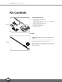
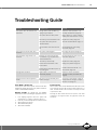
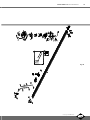
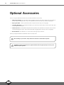
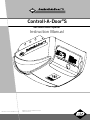
S
®
Controll-A-Door S
Sectional Door Opener
Instruction Manual
Manufacturer’s Part # 79079 (Manual) V1.02
B&D Doors is a division of B&D Australia Pty Ltd
ABN 25 010 473 971
www.bnd.com.au
2
Controll-A-Door ® S Instruction Manual
Controll-A-Door® S
Sectional Door Opener
Safety Rules
Default Settings & Specifications
About Your Opener
03
04
05
Operating Controls
06
Kit Contents
08
Installation
09
C-Rail Attachment
09
Determine Door Type
10
Battery Back Up Installation
21
Mounting - Track Type Door
11
Solar Power System Installation
22
Mounting - Non-Track Type Door
12
How To Use Your Opener
24
Mounting Door Bracket & Arms
13
Transmitter Battery
24
14
Locking
24
14
Manual Release
24
Testing Safety Obstruction Force
15
Power Failure
24
Safety Obstruction Force Test
15
Safety Infra-red Beam
25
Adjusting Safety Obstruction Forces
15
Courtesy Light
25
16
Auxiliary Output
25
For Door Operation
16
Vacation Mode
25
For Courtesy Light Operation
16
Setting The Pet Mode Position
25
For Vacation Mode
17
Maintenance
26
For Auxiliary Output
17
Troubleshooting Guide
27
For Pet (Pedestrian) Mode
18
Parameters
28
Deleting All Transmitter Codes
18
Spare Parts
30
Mounting Wall Transmitter
18
Warranty
32
Programming the Opener
Setting Travel Limits - Control Panel
Coding Transmitters
Accessories
19
Terminal Block
Remote Aerial
19
19
Electric Key Switch
19
Safety Infra-red Beam
20
Controll-A-Door ® S Instruction Manual
Safety Rules
Please read these important safety rules
These safety alert symbols indicate a personal safety or property damage
instruction exists. READ THESE INSTRUCTIONS CAREFULLY.
This automatic garage door opener is designed and tested to offer safe
service provided it is installed and operated in strict accordance with the
following safety rules. Failure to comply with the following instructions may
result in death, serious personal injury or property damage.
CAUTION: If your garage has no pedestrian entrance
door, an emergency access device should be installed.
This accessory allows manual operation of the garage
door from outside in case of power failure.
Position the Garage Door Opener so that the power plug
is accessible when inserted into the power outlet (EN
60335-1).
This opener should be installed in accordance with relevant
Australian Standards.
Do not allow children to play with door controls.
Keep transmitters away from children.
Watch the moving door and keep people away until the
door is completely opened or closed.
Activate the opener only when the garage door is in full
view, free of obstructions and with the opener properly
adjusted.
Keep the garage door balanced. Sticking or binding
doors must be repaired. Garage doors, door springs,
brackets and their hardware are under extreme tension and
can cause serious personal injury. Do not attempt any garage
door adjustment. Do not use if repair or adjustment is needed.
Call for professional garage door service.
Install the optional wall transmitter in a location where the
garage door is visible, but out of the reach of children at
a height of at least 1.5m.
Do not wear rings, watches or loose clothing while
installing or servicing a garage door opener.
This opener is not suitable for commercial, industrial
or common entry applications.
To avoid serious personal injury from entanglement,
remove all unnecessary ropes or chains and disable
any equipment such as locks which are not needed for
powered operation.
Installation and wiring must be in compliance with
your local building and electrical codes. Connect
the power cord only to properly earthed mains. If an
extension lead must be used, make sure it is a 3-core lead
and approved to 7 amp capacity.
If the power cord is damaged, it must be replaced
by the manufacturer, its service agent or a similarly
qualified person in order to avoid a hazard.
This opener is a plug in domestic appliance and is
designed for indoor use only. It must be installed in
a dry position that is protected from the weather.
The opener is not intended for use by young children
or infirm persons without supervision.
WARNING! It is vital for the safety of
persons to follow all instructions. Save
these instructions.
Disconnect electric power to the garage door opener
before removing covers.
Doors requiring over 400N of force to move must have
Safety Infra-red Beams fitted.
B&D Doors to the extent that such may be lawfully excluded hereby expressly disclaims all conditions or warranties, statutory or otherwise which may be implied by laws as
conditions or warranties of purchase of a B&D Garage Door Opener. B&D Doors hereby further expressly excludes all or any liability for any injury, damage, cost, expense or claim
whatsoever suffered by any person as a result whether directly or indirectly from failure to install the B&D Garage Door Opener in accordance with these installation instructions.
© Copyright 2009 B&D Doors
D Power Drive : Instruction Manual
3
4
Controll-A-Door ® S Instruction Manual
Default Settings & Specifications
Factory default settings
Default
Step
Minimum
Maximum
Courtesy light time
3 minutes
10 Sec in battery
backup mode
-
3 minutes
10 Sec in battery
backup mode-
3 minutes
10 Sec in battery
backup mode-
Obstruction force margin
0.7 amps
0.1 amps
0
2.0 amps
Technical specifications
Power supply
230V - 240Va.c. 50Hz
Transformer rating
24Vd.c.
Standby power
2.2 Watts
Motor power
100 Watts
Motor type
24Vd.c permanent magnet
Shuttle travel distance in the C-Rail
2.7m approx. (standard)*
Maximum shuttle travel distance in the C-Rail
3.750 m (with one extension)*
Maximum door opening:
Width:
Height:
Weight:
5500mm (16.5m2)
2150mm
100kg
Minimum headroom
25mm
Short term peak force
700N (70kg)
Lift force
450N (45kg)
Nominal force
150N (15kg)
Receiver type
UHF Multi-frequency FM Receiver
Receiver code storage capacity
8 X 4 button Transmitter Codes
Transmitter frequency
433.47, 433.92, 434.37 MHz
Coding type
Tri-Tran™
Number of code combinations
Over 4.29 billion random codes
Code generation
Non-linear encryption algorithm
Transmitter battery
CR2032 (3 Volts)
Courtesy light
Festoon style lamp 24 volts 15 watt
Controller fuse
10A slow blow
*The actual travel of the door depends on configuration of the connecting arms.
Note: Intermittent operations may occur in areas which experience very strong winds. The strong wind puts extra pressure
on the door and tracks which may in turn intermittently trigger the safety obstruction detection system.
Controll-A-Door ® S Instruction Manual
About Your B&D Opener
Thank you for choosing a Controll-A-Door® S automatic
garage door opener, designed and developed in Australia
by B&D Doors.
Battery Back Up
The technically advanced construction of this opener
ensures you enjoy the following benefits:
In case of a power failure the opener does not lose the
transmitter codes or limit settings.
Warranty
Optional Battery Back Up or solar power is available.
Memory Retention
Five (5) year/10,000 cycles full parts and labour warranty
on motor, electronics and mechanical components of
the opener when installed by an Approved B&D Dealer
(conditions such as annual garage door servicing apply).
Soft Start/Soft Stop
Tri-Tran Frequency Hopping Technology
Manual Release
Every time a transmitter is used, it simultaneously sends a
signal over three different frequencies, reducing the chance
of interference from other radio frequency sources.
Code Hopping Technology
Every time a transmitter is used a new security code
is generated from over 4.29 billion possible code
combinations. This greatly enhances the security of the
system and makes “code grabbing” a thing of the past!
Multi-Channel Transmitter
Multi-channel transmitters allow you to operate other
devices such as an adjoining garage door or automated
gate from the same handy unit.
Warranty Expired Indicator
The opener eases into and out of each cycle making
for smoother and quieter operation, as well as reducing
wear and tear on the door and opener.
The manual release handle allows the door to be
operated by hand in the event of a power failure.
Self Locking
There is no need to manually lock your garage door, as
the opener ‘positively’ locks the door when closed.
Periodic Maintenance Indicator
The SERVICE LED will illuminate to indicate that
periodic maintenance is required. Contact your dealer/
installer for service.
Service Fault Indicator
Flashing LEDs on the control panel easily identify
operational problems or service requirements.
The opener will indicate that the number of cycles covered
by the warranty has been reached by flashing the courtesy
light 10 times after each operation. This flashing will
continue for 20 cycles unless it is reset by pressing the SET
button while the courtesy light is flashing.
Dynamic Door Profiling
S-ALPS (Semi Automatic Limits Positioning
System)
An external aerial can be connected for sites where
radio reception is a problem.
The S-ALPS system does away with manual adjustment of
the door’s limits position using mechanical parts, such as
cams and microswitches.
Safety Reversing System
The automatic safety reverse system significantly reduces
the risk of death or serious injury if trapped by a closing door.
The safety reverse force can be adjusted for environmental
conditions such as windy areas.
Courtesy Light
The courtesy light automatically switches on for
approximately three (3) minutes when operating the door.
This can also be programmed to turn on and off from a
transmitter.
Changing door characteristics are automatically
compensated for and “learnt” with each operation of
the door.
External Aerial
Vacation Mode
A transmitter can be programmed to disable the
garage door opener radio receiver. This is ideal if the
door is to be left idle for prolonged periods.
Pet (Pedestrian) Mode
A transmitter can be programmed to open the door
partially to allow pets access to the garage. The door
opening height is adjustable via a handheld programmer.
Auxiliary Output
You can program a spare button on your transmitter to
operate this output, which can control items that use a
momentary close switching mechanism.
© Copyright 2009 B&D Doors
D Power Drive : Instruction Manual
5
Controll-A-Door ® S Instruction Manual
6
Operating Controls
01.
Terminal Block:
24V PWR is used to power devices such as Safety Infra-red Beams and external receiver (100 milliamp max).
P.E(IR) input is used to connect to Safety Infra-red Beam.
P.E(IR) 0V is a 0 volt connection for Safety Infra-red Beam.
GND is a common -ve ground for accessories
OSC is used for the connection of a wired switch (momentary contact). This switch can then be used to open, stop
or close the door. Install the wall switch in a location where the switch is out of reach of children and the garage door
is visible.
AUX OUT This function allows the opener to operate other devices such as external lights, or an alarm system.
02.
CODING LED (red) light flashes when a code is being stored or when a transmitter button is pressed.
03.
DOOR CODE button is used for storing or erasing transmitter buttons for door operation
04.
SERVICE LED (Yellow) indicates when the opener requires service or repairs.
05.
SET button (Orange) is used during the installation phase together with the Open and MINUS (-) buttons to set the door
limit positions. The Set button is also used to re-initialize the Opener.
06.
OPERATE button (Yellow) is used during installation to test the open, stop and close cycles for the opener. The opener
has to be initialised by the SET button to make the OPERATE button operable.
07.
FORCE MARGIN SET Button: The obstruction force margin is set automatically during installation. The margin can be
adjusted manually using the Force Margin Set button (White). Holding the Force Margin Set button and pressing PLUS
(+) or MINUS (-) buttons will increase or decrease the amount of force. The Force Margin Set should only be used if
environmental factors (wind, etc.) affect the door’s operation.
08.
OPEN LIMIT LED (green) the LED is very helpful during installation. It illuminates and flashes when the door is opening
and remains steady on when the open limit position has been reached.
09.
PLUS (+) button (green) is used during installation to help set the open limit position. Pressing and holding this button
will move the door in the open direction, releasing stops the door.
NOTE: The safety obstruction detection is inoperable when the PLUS (+) button is used to move door.
10.
CLOSE LIMIT LED (red) the LED is very helpful during installation. It illuminates and flashes when the door is closing
and remains steady on when the close limit position has been reached.
11.
MINUS (-) button (red) is used during installation to help set the close limit position. Pressing and holding this button
will move the door in the close direction. Movement stops when the button is released.
NOTE: The safety obstruction detection is inoperable when the CLOSE button is used to move door.
12.
DATUM ADJUST SCREW is used during limits set up to indicate the mid point of the door’s travel.
13.
10A FUSE
14.
PROG INPUT is used to connect the Handheld “PG-3” Programmer for editing control and receiver functions, accessing
diagnostic tools, and activating special features and operating modes.
15.
JP1 SOLAR CONNECTOR the shunt must be fitted for solar operation.
16.
COURTESY LIGHT 15 watts 24 volts festoon type globe is used for courtesy light
Controll-A-Door ® S Instruction Manual
7
Fig. 01
01
02
03
04
05
06
07
08
09
10
11
12
16
15
14
13
© Copyright 2009 B&D Doors
D Power Drive : Instruction Manual
Fig. 02
Controll-A-Door ® S Instruction Manual
8
Kit Contents
Powerhead Unit (Fig. 03)
Fig. 03
1 x Controll-A-Door® S powerhead
1 x Transmitter pack
(Pack includes one TB-2 and one TB-4 keyring
transmitters with batteries)
1 x Wall mount transmitter with battery
2 x Door attachment arms
1 x Accessory and hardware pack
1 x Installation Manual
PLUS
Single Piece C-Rail with Pre-Assembled Chain
(Fig. 04)
Fig. 04
NOTE: Chain in one piece rail has been tensioned by the
factory. Do not adjust the tension of the chain.
IMPORTANT NOTE: If a modification to the length of the
track is required, the adjustment must be made from the
powerhead end only.
Controll-A-Door ® S Instruction Manual
9
Installation
C-Rail Attachment
Step 1 - Attach C-Rail to Powerhead
Shaft
Locate and insert the powerhead’s shaft into the C-Rail’s
sprocket as shown in (Fig. 05).
Fig. 05
Locate shaft into
sprocket
Step 2 - Secure C-Rail to Powerhead
Fix the two track brackets as shown in (Fig. 06). Fix with
the four screws supplied in accessory pack.
Screw M4 X 8
2)
t (x
cke
a
r
b
ck
Tra
Fig.06
© Copyright 2009 B&D Doors
D Power Drive : Instruction Manual
10
Controll-A-Door ® S Instruction Manual
Determine the Door Type
Step 3 - Determine the Door Type
Proceed from Step 4
Determine which type of garage door you have as illustrated
in (Fig. 7) to (Fig. 9).
Track
For a sectional (panel) door on tracks (Fig. 7)
proceed with the installation from Step 4.
Fig. 7
Door
Sectional door with track
For a one piece door on tracks (Fig. 8)
proceed with the installation from Step 4.
Proceed from Step 4
Track
Fig. 8
Door
One piece door with track
Proceed from Step 8 on page 12
Door
Fig. 9
One piece door without track
For a one piece door without tracks (on springs) (Fig. 9)
proceed with the installation from Step 8 (page 12).
Controll-A-Door ® S Instruction Manual
11
Mounting - Track Type Door
Step 4 - Determine Bracket Position
a.
b.
c.
Open the door and find the highest point of travel of
the top door panel.
Using a level, transfer this height to the wall above the
door (Fig. 10) and mark a line 60mm above it.
Determine the centre point on the wall above and on
top of the door. Then draw two (2) lines extending
21.5mm from each side of the centre point. (Fig. 11)
Level
Level
Track
Track
Fig. 10
Door
Door
Step 5 - Mounting the Wall Bracket
a.
b.
c.
Centre the bracket over the intersection of these two
lines. Mark centres for at least two holes (Fig. 11).
•
Ensure a solid mounting point is behind
these holes.
Drill holes into the wall with an appropriate sized bit.
Secure bracket to the wall using:
IF CONCRETE OR BRICK - 8mm or 5/6 loxins or
dynabolts.
IF TIMBER - wood screw #20 or equivalent
(minimum 50mm long).
3
4 .5
21
.5
21
Fig. 11
WARNING: Make sure concrete, brick wall
or timber lintels are solid and sound so as to
form a secure mounting platform.
Drilled holes
Step 6 - Attach the C-Rail to the Wall Bracket
a.
b.
Attach the C-Rail assembly to the wall bracket with the
90mm long clevis pin and secure with the supplied
snap pin (Fig. 12).
Leave the powerhead in its packing box for protection
during installation.
Step 7 - Securing the Powerhead to the Ceiling
a.
b.
c.
d.
e.
Raise the powerhead from the packing box and
support it in the horizontal position with a step ladder.
Open the garage door. Rest the opener on the open
door and use a scrap piece of wood to bring it to
horizontal level.
Line up the track perpendicular to the wall.
Secure the perforated angle (not supplied) to the
ceiling above where powerhead’s mounting holes will
be once fully installed. A representative mounting is
shown (Fig. 13).
Connect the powerhead to the ceiling mounted
perforated angle with M8x20mm screws and nuts.
Strips should not extend more than 18mm below
centre of powerhead mounting holes (Fig. 13).
Fig. 12
Structural member
Fig. 13
For an alternative mounting option, go to Step 10.1
WARNING: The opener must be securely
fastened to structural supports, otherwise
opener failure may ensue causing serious
personal injury and/or property damage.
© Copyright 2009 B&D Doors
D Power Drive : Instruction Manual
12
Controll-A-Door ® S Instruction Manual
Mounting - Non Track Type Door
Centre of door
WARNING: Make sure concrete, brick wall
or timber lintels are solid and sound so as to
form a secure mounting platform.
Fig. 14
Step 8 - Determine the Door’s Centre
a.
b.
Find the centre of the door and mark this location both
above the door and on top of the door.
Draw two lines 21.5mm either side of this (Fig. 14).
Step 9 - Prepositioning the Opener
a.
b.
c.
Raise the door to open position.
Rest the opener on the top edge of the door with end
of the C-Rail against the wall (Fig. 18).
Support the powerhead level with the lowest point of
the open door (Fig. 15).
NOTE: Do not slide C-Rail along the face of the door.
Fig. 15
Step 10 - Mounting the C-Rail
a.
Step
Ladder
b.
c.
d.
e.
f.
C rail
g.
Fig. 16
Highest point
of door travel
Door
Step
Ladder
h.
Close the door slowly. The C-Rail will be elevated by
the top edge of the door as it moves.
Stop the door when it is at its highest point of travel.
Allow 25mm additional height for clearance between
the door and the track (Fig. 16).
Support the C-Rail in this position and close the door
The height determined in Step 11(b) will be the height
at which to mount the wall bracket.
Centre the bracket along the line determined in Step 9.
Using the bracket as a template, mark a minimum
of two holes and drill with appropriate size bit. For a
more secure fitting, the wall bracket can be anchored
using more than two holes.
Secure the bracket to the wall using:
IF CONCRETE OR BRICK - 8mm or 5/6 loxins or
dynabolts.
IF TIMBER - wood screw #20 or equivalent
(minimum 50mm long).
Attach the wall bracket to the C-Rail with the 90mm
long clevis pin (Fig. 17) and secure by a snap pin.
Step 11 - Securing the Powerhead to the Ceiling
a.
b.
Fig. 17
Secure the perforated angle (not supplied) to the
ceiling above where powerhead’s mounting holes will
be. See (Fig.13) for a representative mounting.
Connect the powerhead to the ceiling mounted
perforated angle with M8x20mm screws and nuts.
Strips should not extend more than 18mm below
centre of powerhead mounting holes (Fig. 13).
WARNING: The opener must be securely
fastened to structural supports, otherwise
opener failure may ensue causing serious
personal injury and/or property damage.
Controll-A-Door ® S Instruction Manual
13
Mounting Door Bracket and Arms
Step 11.1 - Alternative Mounting Option
Drill hole at centre of
track (recommended bolt
size M6 or M8)
The opener can be fastened to the roof by driving a bolt
through the C-Rail into a structural timber support. The bolt
head’s height must not exceed 6mm (Fig. 18).
Fig. 18
Ceiling
Step 12 - Mounting Door Bracket
The door bracket comes in two parts. The bottom plate
with two mounting holes is used on its own for one piece
doors. For sectional doors, the top plate is placed over the
bottom plate and is fixed with four (4) screws (Fig. 19).
a.
b.
The height of bolt
head must not
exceed 6 mm
Steel rail
Shuttle assembly
Mount the door bracket, or bracket assembly, on the
door’s centre line one-third down the top panel (Fig.
19) using M6 or equivalent screws (not supplied),
STEEL DOORS ONLY: Bracket can be welded in
place.
Fig. 19
NOTE: If in doubt about the door’s strength,
reinforcement may be added to the door’s
frame where necessary. Door damage may
occur if the bracket is installed on a panel
with insufficient strength. The opener’s
warranty does not cover damage caused to
the door and/or door panels.
Step 13 - Attaching the Arms
FOR SECTIONAL AND ONE PIECE DOORS WITH TRACK:
a. Assemble the bent and straight arms with bolts
and nuts supplied in the accessory pack (Fig. 20).
Always use both bent and straight arms.
b. Connect the assembled arm to the bracket and the
disengaged trolley with clevis and snap pins. The
angle “A” must be more than 10° (Fig. 20).
0
10
A
Fig. 20
WARNING: Connecting the bent arm other
way around may damage the door.
FOR ONE PIECE DOORS WITHOUT TRACK
a. Assemble the bent and straight arms as shown in (Fig.
21) with bolts and nuts supplied in the accessory
pack. Always use both the bent and straight arms.
b. Connect the assembled arm to the bracket and the
disengaged trolley with clevis and snap pins.
c. If installing on a door with a bad wave action,
lengthening the arm will assist in reducing this effect.
Fig. 21
IMPORTANT NOTE - If the manual release
handle is more than 1.8 metres from floor level
when the opener is installed, extend the handle
to a height less than 1.8 metres.
© Copyright 2009 B&D Doors
D Power Drive : Instruction Manual
Controll-A-Door ® S Instruction Manual
14
Setting Travel Limits
IMPORTANT NOTE: The OPERATE button
will not function until the open and close limit
positions are set.
NOTE: The door and shuttle must be engaged
into the chain index. The door should be open
approximately half way.
Fig. 22
Note: If Safety Infra-Red Beam are to be used
they must be installed before setting the travel
limits.
Step 14.1 - Setting Limits Positions
Remove the controls cover to access the controls panel as
shown in (Fig. 22). Replace it when setup is completed.
Step 14.2 - Connect Power to the Drive unit
Plug the power cord into a mains point and switch power
on. The red CLOSE LIMIT LED will be flashing.
WARNING: The safety obstruction detection
system is inoperable while MINUS (-) and
PLUS (+) drive buttons are being used and
travel limits are not set.
Fig. 23
Step 14.3 - Set the Datum Position
a.
b.
Press and hold the MINUS (-) or PLUS (+) buttons to
move the door to the halfway position. Ensure that the
door, shuttle and chain index are engaged.
Using a small screwdriver, turn the DATUM ADJUST
screw until the STATUS LED comes on (Fig 23).
Note: If the STATUS LED is already illuminated when the
door is halfway up, turn the DATUM ADJUST screw until
the light goes off, then turn back one notch to illuminate
again.
Step 14.4 - Set the Limits Positions
a.
Fig. 24
b.
c.
Press and hold the MINUS (-) button until the door
reaches the desired close limit position. Single presses
will inch the door closed (Fig 24).
Press the SET button to store the close position into
memory (Fig. 24).
Press and hold the PLUS (+) button until the door
reaches the desired open limit position. Single presses
will inch the door open (Fig. 24).
WARNING: The door will automatically close,
open and close again once Step 12.4(d) is
performed. Ensure that no persons or objects
are in the door’s path.
d.
e.
Press the SET button to store the open position into
memory (Fig. 24).
The door will now automatically close and open to
calculate the safety obstruction settings. After this, the
opener can be operated with the OPERATE button.
Controll-A-Door ® S Instruction Manual
15
Testing Safety Obstruction Force
CAUTION: Take care when testing the safety
obstruction force. Failure to follow this
warning can result in serious personal injury
and/or property damage.
Step 15.1 Test the Close Cycle
a.
b.
c.
d.
Press the OPERATE button to open the door (Fig. 25).
Place a piece of timber approximately 40mm high on
the floor directly under the door (Fig 26).
Press the OPERATE button to close door.
The door should strike the object and re-open.
Fig. 25
Step 15.2 Testing the Open Cycle
a.
b.
c.
Press the OPERATE button to close the door (Fig. 25).
Press again to open the door.
When the door reaches approximately half way, firmly
grab the door’s bottom rail - the door should stop.
If the door does not reverse readily when closing, or stop
when opening, the force may be excessive and need
adjustment, refer to Step 13.4.
IMPORTANT WARNING: If the door is closing
and is unable to re-open when obstructed,
discontinue use. Do not use a door with faulty
obstruction sensing. Repair fault and re-test
before using.
Fig. 26
Adjusting Safety Obstruction Force
The safety obstruction force is calculated automatically
and normally does not require adjustment. The only time
the force may need to be adjusted is due to environmental
conditions, such as areas that are windy, dusty or have
extreme temperature changes that affect the operability
and movement of the door.
Step 15.4 - To Decrease Force Pressure
a.
b.
WARNING: Doors requiring over 400N of force
to move must have Safety Infra-red Beams fitted
for safety.
Step 15.3 - To Increase Force Pressure
a.
b.
c.
d.
e.
Press and hold the FORCE MARGIN SET button (Fig
25).
While holding down the FORCE MARGIN SET button,
press the PLUS (+) button.
Each press will increase the force margin one step.
The OPEN LIMIT LED will flash each time the PLUS
(+) button is pressed to indicate an increase in force.
Test the force again as per Steps 13.1 and 13.2.
If the OPEN LIMIT LED flashes continuously when the
PLUS (+) button is being pressed, this indicates that
the maximum force setting has been reached.
c.
d.
e.
Press and hold the FORCE MARGIN SET button
(Fig 25).
While holding down the FORCE MARGIN SET
button, press the MINUS (-) button.
Each press will decrease the force margin one
step. The CLOSE LIMIT LED will flash each time
the MINUS (-) button is pressed to indicate a
decrease in force.
Test the force again as per Steps 13.1 and 13.2.
If the CLOSE LIMIT LED flashes continuously
when the MINUS (-) button is being pressed,
this indicates that the minimum force setting has
been reached.
Step 15.5 - To Recall Factory Set Force
a.
b.
Holding down the FORCE MARGIN SET button
and the SET button for two seconds.
Release both buttons. The default setting should
now be recalled.
© Copyright 2009 B&D Doors
D Power Drive : Instruction Manual
16
Controll-A-Door ® S Instruction Manual
Coding Transmitters
Step 16.1 - Storing the Transmitter Code
The opener can only operate from transmitters that have
been programmed into its receiver. The receiver needs to
learn the codes of any transmitter that will be used with the
operator. Up to eight (8) codes can be stored in the receiver’s
memory.
Fig. 27
a.
b.
c.
d.
Press the DOOR CODE button and release. The
DOOR CODE LED will illuminate to indicate the
opener is in Code Learn mode. If a valid code is
not stored within 15 seconds the opener will exit
Code Learn (Fig. 27).
Press the transmitter button (one of four) that you want
to control the door. The DOOR CODE LED will begin
to flash.
Press the same transmitter button again. The DOOR
CODE LED will illuminate for one second and then go
out.
The transmitter is now coded to operate the door - press
the button to test.
Step 16.2 - Setting the Transmitter to Operate the
Courtesy Light
Fig. 28
Although the courtesy light comes on with each operation of
the opener, it may also be controlled by a transmitter without
operating the door.
a.
b.
c.
d.
Press the DOOR CODE button twice. The DOOR CODE
LED will illuminate and the courtesy light will turn on to
indicate that the light code learning is active (Fig. 28).
Choose a transmitter button not already coded into the
receiver. Press this button and the DOOR CODE LED
will begin to flash.
Press the same transmitter button again. The DOOR
CODE LED will illuminate for one second and then go
out.
The transmitter is now coded to operate the light - press
the button to test.
Controll-A-Door ® S Instruction Manual
17
Coding Transmitters
Step 16.3 - Setting the Transmitter to Operate
Vacation Mode
The opener can be programmed into a “Vacation Mode”
where the opener will not respond to any transmitter except
one preprogrammed unit.
a.
b.
c.
d.
e.
Press DOOR CODE button three times. The DOOR
CODE LED will illuminate and the courtesy light will
flash slowly (once every two seconds) to indicate
Vacation learning mode is active. (Fig. 29)
Choose a transmitter button not already coded into the
receiver. Press this button and the DOOR CODE LED
will begin to flash.
Press the same transmitter button again. The DOOR
CODE LED will illuminate for one second and then go
out, and the courtesy light will also switch off. This
indicates the code has been stored (Fig. 29).
To activate Vacation Mode, close the garage door and
press the coded button transmitter for 5 seconds. The
DOOR CODE LED will illuminate to indicate that the
opener is in Vacation Mode.
To exit Vacation Mode press the transmitter button
momentarily until the DOOR CODE LED turns off.
Fig. 29
Fig. 30
Step 16.4 - Setting the Transmitter to Operate the
Auxiliary Output
It is possible to operate other devices (e.g. alarm systems)
using one of the spare buttons of a multi-channel transmitter
coded into the Auxiliary Output feature.
a.
b.
c.
Press DOOR CODE button four times. The DOOR
CODE LED will illuminate and the courtesy light will
flash quickly (twice per second) to indicate that
learning mode for the Auxiliary Output is active.
Choose a transmitter button not already coded into the
receiver. Press this button and the DOOR CODE LED
will begin to flash.
Press the same transmitter button again. The DOOR
CODE LED will illuminate for one second and then go
out, and the courtesy light will also switch off. This
indicates the code has been stored (Fig. 30).
© Copyright 2009 B&D Doors
D Power Drive : Instruction Manual
18
Controll-A-Door ® S Instruction Manual
Coding Transmitters
Step 16.5 - Setting the Transmitter to Operate Pet
(Pedestrian) Mode
The opener can be programmed into a “Pet Mode” where the
door opens partially to allow pets to enter/exit the garage:
Fig. 31
a.
b.
c.
d.
Press the DOOR CODE button five times, the DOOR
CODE LED will illuminate and the courtesy light will flash
quickly (twice per second) to indicate learning mode for
Pet Mode is active.
Choose a transmitter button not already coded into the
receiver. Press this button and the DOOR CODE LED
will begin to flash.
Press the same transmitter button again. The DOOR
CODE LED will illuminate for one second and then go
out, and the courtesy light will also switch off. This
indicates the code has been stored. This indicates the
code has been stored (Fig. 31).
The opening height of the door for pet position can only
be changed with universal programmer.
Step 16.6 - To Erase Programmed Codes
Fig. 32
Fig. 33
If the DOOR CODE button is pressed and held for 6 seconds
the DOOR CODE LED will blink rapidly for one second to
indicate that all programmed codes have been erased. (Fig.
32)
Step 16.7 - Installation of the Wall Mounted
Transmitter
a.
b.
c.
Mount the transmitter in a convenient location, yet out
of reach of children and at least 1.5m off the ground
(Fig. 33).
Make sure the door is visible from this location.
To set the transmitter codes refer to Step 16.1.
Controll-A-Door ® S Instruction Manual
19
Accessories
Step 17.1 - Terminal Block
A variety of wired accessory items can be connected to the
terminal block such as Safety Infra-red Beams, electric key
switch and more (Fig. 34).
The terminal block also features auxiliary output for
controlling other devices from your transmitter. These can
include: an alarm system, external lighting, or an automatic
gate.
Terminal connections from top down are as follows:
1. 30V PWR (+ve)
2. P.E (Safety Infra-red Beam input)
3. P.E 0V (0V for Safety Infra-red Beam)
4. GND (Common -ve ground for accessories)
5. OPERATE (Open/Stop/Close trigger)
6. AUX OUT (Auxiliary output trigger)
PWR
PE (IR)
PE (IR) 0V
Fig. 34
GND
OSC (OPERATE)
AUX
Step 17.2 - Remote Aerial (Part No 062177)
Some sites cause poor radio reception. Particularly
problematic areas are those where there is a large amount
of metal, like an all steel garage, or an underground car
park with large masses of steel reinforced concrete. These
issues, and others, can create radio reception issues.
Poor radio reception will be noticed by a reduction in the
operating range of the transmitters.
30V PWR
P.E
P.E 0V
GND
OPERATE
AUX OUTPU
You can evaluate whether fitting an external aerial will
benefit as follows:
test the maximum operating range of the transmitter
•
with the garage door closed; then
test the maximum operating range of the transmitter
•
with the garage door open.
If the range improves when the door is open you can install
a remote aerial kit to improve reception.
Mount the aerial to a suitable location on the outside of
the garage. Similar to a television aerial, the better the
mounting position the better the reception will be. Where
possible, mount the aerial as high as possible, away from
masses of metal and in a line of sight position to where you
normally use your transmitter.
Step 17.3 - Electric Key Switch (Part No
062738)
An electric key switch provides an alternative to using a
transmitter. Each key turn cycles through an open/stop/close
function. The electric key switch is also an external release
mechanism - ideal for garages only with one entrance. To
connect the switch to the opener’s terminal block refer to
(Fig. 35) and the Electric Key Switch’s instruction sheet.
© Copyright 2009 B&D Doors
D Power Drive : Instruction Manual
Fig. 35
20
Controll-A-Door ® S Instruction Manual
Accessories
IMPORTANT NOTE - The Safety Infra-red
Beam must be installed and connected before
the travel limits are set - See Step 12.
3
4
WARNING: Doors requiring over 400N of force
to move must have Saftey Infra-red Beams fitted
for safety.
5
Fig. 36
Step 18 - Safety Infra-red Beam
Safety Infra-red Beam extends across the door opening. This
Safety Infra-red Beam is designed to detect an obstruction
while the door is closing and to send a signal to the door
opener to reverse or stop the door movement.
2
6
1
Step 18.1 - Fitting Safety Infra-red Beam
a.
b.
c.
a.
Fig. 37
b.
Attach the mounting bracket (4) to adjustment bracket
(3) with the pan head screw (6) (supplied) (Fig. 36).
Attach the PE 2000TS bracket (2) to Safety Infrared Beam transmitter (IR-200TS-TX) with four taptite
screws (m3x5) and attach the other side to adjustment
bracket (3) with the pan head screw (6) (supplied).
Repeat steps a and b to assemble the Safety Infra-red
Beam ( IR-200TS-RX).
Locate the Safety Infra-red Beam in a strategic location
in the gateway. B&D recommend that the sensor is
placed 150 mm above the floor level. Connect as per
the wiring diagram (Fig. 38).
Use 2.2 kilo ohm resistor with the colour code red, red,
red and gold on the Safety Infra-red Beams receiver
between the V- and NC terminals as shown in (Fig.
38).
Step 18.2 - Alignment
a.
b.
R1
c.
R1
Fig. 38
R1=2.2K OHM
RED,RED,RED,GOLD
.25WATT 5% TOLERENCE
RESISTANCE
BLACK
BLACK
BLACK
YELLOW
RED
RED
RED
BLACK
YELLOW
Power up the Safety Infra-red Beam. The green LED on
the transmitter and red LED on the receiver should turn
ON to indicate power is present.
If the receiver is connected to power and the red LED
is on while the green LED is on, the transmitter and
receiver are not aligned.
Make horizontal and/or vertical (Fig. 37) adjustment
on the transmitter and/or receiver until the red LED
turns off on the receiver, indicating alignment.
WARNING: When using Safety Infra-red Beam,
the doorway must be clear of all obstructions
and persons at all times. The location of the
beams and manner in which it is installed
might not give safety protection at all times.
Check to make sure that the height of the
beam and type used give maximum protection
possible.
V- IN V+
P.E BEAM
WARNING: Install the Safety Infra-red Beam
as per diagram in Fig. 38. Tampering with the
Safety Infra-red Beam could result in serious
personal injury and/or property damage and
will void the warranty.
Controll-A-Door ® S Instruction Manual
21
Battery Back Up Installation
Fig. 39
Step 19 -Battery Back Up (optional)
The opener has provision for a Battery Back Up kit that
allows continued operation of the door in the absence of
mains power.
Step 19.1 -Installation
1.
2.
3.
4.
5.
6.
Disconnect power to the opener.
Remove screws and swing the cover open (Fig. 39).
Use battery pack # 1. Mount battery pack and secure
with item 11 and 13.
Mount the pcb support item16 on to chassis with item
12 and install the SBY-3 item 8 Charger Board on to
the pcb support with item 14 screws.
Feed the 2-wire battery harness item 10, through the
grommet on the base plate and connect to the SBY3.
Feed the charger harness from SBY-3 to the control
board. Plug the 4-pin connector marked “SBY-3”
onto the control board.
Warning: After the next step the opener may
become active (even when power is off) due to
a residual charge in the batteries.
7. Connect item 5 and 10 together (Fig 39).
8. Reconnect the power.
Step 19.2 -Testing Battery Back Up
1.
2.
Press either the OPERATE button or transmitter
to activate the opener.
Whilst the door is in motion disconnect mains
power - the opener should continue to operate.
Note: Wait for the door to complete its
travel before proceeding to the next step
3.
4.
Press either the OPERATE button or transmitter
to activate the opener.
Whilst the door is in motion re-connect power.
The door should complete the cycle as normal.
Step 19.3 -Troubleshooting
If door stops or moves very slowly under battery power,
then the batteries may have little to no charge.
To remedy this connect mains power and leave the
batteries to charge. The batteries may take 24 to 48
© Copyright 2009 B&D Doors
D Power Drive : Instruction Manual
Controll-A-Door ® S Instruction Manual
22
Accessories
SmartSolar™ Installation
WARNING: Do not connect batteries until
Step 20.3
S
S
Step 20.1 - Mount the Charger Board
a.
b.
Fig. 40
c.
d.
e.
f.
g.
Disconnect power to the opener.
Swing open the light diffuser and controls cover. Remove
screws marked “S” above in Fig. 40 and lift up the main
cover.
Remove the transformer and mains power cable.
Mount the PCB support with two screws .Secure the
SCG01-200 charger board on to PCB support with 3
screws. (Fig. 41).
Plug the solar charger Board’s three wire harness (red/
yellow/black) into the control board’s “SBY-3” connector
on the control board.
Plug the Charger Board’s white one wire harness into
the control board’s “24vac in” connector.
Plug the solar shunt (supplied) onto the control board’s
“JP1” solar connector.
IMPORTANT Warning: Do not connect battery
or solar panel polarity incorrectly - this will
result in serious damage to components.
Fig. 41
Step 20.2 - Connect the Solar Panel
a.
b.
c.
Warning: During Step 20.3 the opener will
become active.
Black
Yellow
Red
Fig. 43
Step 20.3 - Mount & Connect the Battery
e
Whit
ttery)
ire
W
ck
ire
a
l
B
dW
e
R
Red (From Ba
ttery)
Black (From Ba
Red (From Solar P
anel)
olar Panel)
Black (From S
Fig. 42
Mount the solar panel as outlined in the SmartSolar™
Installation Manual.
Feed the Solar Panel’s cable through black grommet
located on the top of the metal plate.
Connect the red wire to the Charger Board’s “SOLAR+”
connector, and the black wire to the “–SOLAR”
connector (Fig. 42).
a.
b.
c.
d.
e.
f.
Mount the Battery Box close to the opener.
Feed the 2-core 18awg gauge cable (supplied) through
the Battery Box’s grommet.
Connect the red wire to the Battery Box’s “+” terminal,
and the black wire to the “–” terminal (Fig. 43).
Feed the other end of the battery cable through the Drive
unit’s black grommet located on the metal plate.
Connect the red wire to the Charger Board’s “BAT+”
connector, and the black wire to the “–BAT” connector
(Fig. 42).
Refit the light diffuser and main cover.
Step 20.4 - Re-setup and Test the Opener
a.
b.
Setup travel limits and code transmitters.
Press either the OPERATE button or use a transmitter to
operate the opener.
Controll-A-Door ® S Instruction Manual
How to use your opener
For maximum efficiency of your opener, your garage door
must be in good operating condition.
An annual service of your garage door by an Approved
Dealer is recommended.
CAUTION - Activate the opener only when
the door is in full view, free of obstructions
and with the opener properly adjusted. No one
should enter or leave the garage while the
door is in motion. Do not allow children to
play with or near the door.
Fig. 44
WARNING! This opener is a mains voltage
plug-in domestic appliance and there are no
user serviceable parts inside this opener.
Transmitter
•
•
•
•
To operate the opener, press the programmed
transmitter button until your door begins to move
(usually 2 seconds). Make sure you can see the door
when you use the transmitter.
If you are in a vehicle you should aim the transmitter
through your windscreen (Fig. 44).
Check that the door is fully closed before you drive
away.
If you press the transmitter whilst the door is moving
the door will stop. The next press of the transmitter will
move the door in the opposite direction.
The transmitter may also be programmed to operate the
following features (see Pages 16 to 18 for full details):
•
to turn the courtesy light on and off without operating
the door,
•
to activate the Auxiliary Output,
•
to put the door into “Pet Mode” where it opens partially
to allow pet access to the garage, and/or
•
to put the garage door opener into “Vacation Mode”
where it will not respond to any transmitters.
NOTE: Additional transmitters may be purchased at any
time.
© Copyright 2009 B&D Doors
D Power Drive : Instruction Manual
23
24
Controll-A-Door ® S Instruction Manual
How To Use Your Opener
Removing the Battery From the Transmitter
(Battery Type: 3V Lithium Battery CR2032).
Use a non-metallic object (e.g. pen) to remove the battery.
(Fig. 45)
Inbuilt Locking Facility
DO NOT lock your door when your opener is engaged as it
has inbuilt locking facility. With the opener engaged your
door will be locked whether the power is on or off.
Fig. 45
Manual Door Operation
CAUTION: when operating the manual release
while the door is open. The door may fall
rapidly due to weak or broken springs, or due
to being improperly balanced. (AS3350)
CAUTION! Do not disengage the opener to
manual operation with children/persons or
any objects including motor vehicles within
the doorway.
To disengage the opener from the door (preferably with
the door in the closed position), pull down on the string
handle on an angle towards the door. This will allow you to
manually open or close the door. To re-engage the opener
pull the string handle away from the door.
WARNING! When the opener is manually
disengaged, the door is no longer locked. To
lock the door manually, re-engage the opener
after the door is closed.
Power Failure
When there is a power failure, the opener will be unable to
automatically open or close your garage door. To use your
door whilst there is no power you will need to disengage the
opener and use the door manually – see Manual Operation
above.
REPLACE BATTERY WITH CR2032 ONLY
Controll-A-Door ® S Instruction Manual
How To Use Your Opener
Safety Infra-red Beam
A Safety Infra-red Beam Kit may be fitted to this
opener.
•
When this option is fitted, the operation of this
device is such that if an object (i.e. car, child,
etc.) blocks the Safety Infra-red Beam, then
the garage door opener will not close the door
automatically.
•
If the Safety Infra-red Beam is fitted but not
operating correctly, then the door once opened
automatically, will not close automatically. The
door may be closed by reverting to manual
operation – see Manual Operation.
open partially.
See Step 16.5 for more information.
Courtesy Light
The Courtesy Light will illuminate for approximately
three (3) minutes each time the door is operated
automatically.
Spare buttons of a multi-channel transmitters can be
programmed to turn the light on and off by remote
control.
See Step 16.2 for more information.
Auxiliary Output
This function allows the opener to operate other
devices such as external lights or an alarm system.
To use this function, a spare button of a multi-channel
transmitter must be programmed to operate the
Auxiliary Output feature.
See Step 16.4 for more information.
Vacation Mode
The radio receiver of the garage door opener can be
turned off to all but one transmitter via Vacation Mode.
Whilst in vacation mode the opener will not respond to
any transmitter.
To activate the Vacation Mode facility, see Step 16.3.
NOTE - program only one button to control “Vacation
Mode”. This will reduce the possibility of accidental
activation of this feature.
Pet (Pedestrian) Mode
A transmitter can be programmed to open the door
partially to allow pet access to the garage.
To activate Pet Mode press the transmitter button that
has been programmed for Pet Mode - the door will
© Copyright 2009 B&D Doors
D Power Drive : Instruction Manual
25
26
Controll-A-Door ® S Instruction Manual
Maintenance
Maintenance
The SERVICE LED will indicate the requirement for a service
and/or adjustment. To reset the SERVICE LED when the
door is serviced, reprogram the Door Travel Limits and the
Door Travel Force – on completion of this programming the
SERVICE LED will go out.
Whilst your opener does not require any periodic
maintenance, the door that it is fitted to does. Your garage
door is a large, heavy, moving object and should be
tested regularly to ensure it is in good condition. A poorly
maintained door could cause fatal or serious injuries or
serious damage to property.
To ensure a long and trouble free life for your opener the
following is recommended:
Monthly
•
•
Disengage the opener and manually operate the door:
The door must be smooth to operate by hand. An
operating force on the bottom rail should not exceed
150N (15kg) force.
Each month check that the opener reverses when the
door contacts a 40mm high object placed on the floor
(AS3350). Refer to Testing the Safety System (Step
16).
NOTE: If the door does not operate smoothly, call your
nearest Approved Dealer.
Yearly
CAUTION: Frequently examine door,
particularly cables, springs and
mountings for signs of wear, damage
or imbalance. Do not use if repair or
adjustment is needed since a fault in the
installation or an incorrectly balanced
door may cause injury. (AS3350)
Adjustments should only be carried out
by experienced persons, as this function
can be dangerous if not performed under
strict safety procedures.
WARNING! Failure to maintain your
garage door may void the warranty on
your garage door opener.
Warranty Expired Indicator
When the opener reaches the number of cycles
covered by warranty the courtesy light will flash 10
times after each operation to indicate that the warranty
has expired. This flashing will continue for twenty (20)
operations unless the user acknowledges the warranty
expiry indicator and stops the light from flashing. To
stop the courtesy light flashing press the SET button
while the light is flashing after an operation.
B&D suggests that you contact your nearest Approved
Dealer to perform an annual door service.
Service Record
Record any maintenance in the following table to assist in any warranty service.
Date
Service by
Signature
Invoice No.
Amount
Controll-A-Door ® S Instruction Manual
Troubleshooting Guide
Symptom
Possible cause
Remedy
The opener does not work from the
transmitter
Garage door in poor condition e.g.
springs may be broken
Check the door’s operation - see
monthly maintenance (Page 26)
The opener does not have power
Plug a device e.g. a lamp, into the
power point and check that it is OK
The battery in the transmitter is flat
Replace the battery (Page 24)
The opener has been put into
“Vacation Mode”
Turn off “Vacation Mode” (Page 17)
The transmitter code has not been
set
See transmitter & code setting
procedure (Page 16)
The motor runs but the door does
not move
The opener is disengaged
Re-engage the opener (Page 24)
The transmitter range varies or is
restricted
Variations are normal depending
on conditions e.g. temperature or
external interference
See instructions for correct use of
transmitter (Page 23)
The battery is flat or faulty
Replace the battery (Page 24)
Position of the transmitter in the
motor vehicle
Change the position (Page 23)
Position of the aerial will not pick up
the radio signal
Install an external aerial kit – see
Accessories (Page 19)
The light does not work
Light module is not inserted/
connected properly
Check for correct connection
otherwise contact your dealer for
support
The door reverses for no apparent
reason
This may occur occasionally from
weather changes
The opener automatically adjusts to
compensate for changes, to adjust
the force see (Page 15)
If You Need a Service Call
If the opener needs service please call the dealer who
installed the garage door opener (for product assistance
contact 13 62 63 within Australia).
BEFORE CALLING you should have the following
information to assist in providing the appropriate service:
1.
2.
3.
4.
5.
Has anything happened since the opener last
operated OK, e.g. a storm, a jolt to the door etc.?
How easy is it to manually open and close the door?
What model is the opener?
Who installed the opener?
When was it installed?
Fault Indicator
When a fault is detected the SERVICE LED will start to flash
and a number of beeps will sound to indicate that there is a
fault. The fault will be active each time an attempt is made
to operate the door.
Pressing the SET button will reset the opener. If the fault
continues to be tripped contact an Approved Dealer for
assistance.
© Copyright 2009 B&D Doors
D Power Drive : Instruction Manual
27
28
Controll-A-Door ® S Instruction Manual
Parameters
Door status indicators
Door opener state
OPEN LED (green)
Open
On
Close
Opening
CLOSE LED (red)
Beeper
On
Flashing
Closing
Flashing
Door travel stopped
Flashing
Door obstructed when opening
Flashing
Door obstructed when closing
Flashing
Flashing
Opener overloaded
Alternating flashes
Mains power interrupted
Rapid flashes
Beeps while door is
moving
Alternating flashes
Button
Function
OPERATE
Opens/stops/closes the door
DOOR CODE
Codes a transmitter button for operate function
FORCE MARGIN SET & PLUS (+)
Increases the obstruction force margin setting
FORCE MARGIN SET & MINUS (-)
Decreases the obstruction force margin setting
FORCE MARGIN SET (then) SET
Reloads the factory set default obstruction force margin setting
(-) (for 6 seconds)
Clears the door limits set positions. Limits then need to be reset
SET (the power on) and hold until all
LEDs are off
Deletes control parameters excluding transmitter storage memory
DOOR CODE press and hold until
DOOR CODE LED starts flashing
Deletes all transmitter storage memory
SET & DOOR CODE (the power on)
and hold until all LEDs are off
Deletes all control parameters and transmitter storage memory
Controll-A-Door ® S Instruction Manual
© Copyright 2009 B&D Doors
D Power Drive : Instruction Manual
29
60379
64053
16232
61733
10570
5 GEARD MOTOR ASSY 16V2 55RPM
6 HELICAL GEAR 59 - 1M CP
7 TIMING SUPPORT VP3
8 RATCHET TIMING ASSY
9 TAPTITE SCREW “P” M4x10
10361
65421
67575
71415
72127
62116
65440
64653
60276
61453
64698
64921
62941
63005
62950
71643
65790
18 TERMINAL BLOCK 500/02DS
19 CAP POLYFILM 0.1UF KX2 275VAC
20 MAIN COVER VP4 BK CADS SP AY
21 LIGHT DIFFUSER VP4 B&DSP
22 CONTROLS COVER VP4 SP TRD
23 GLOBE 24V/15W 15x44
24 C RAIL TRACK 77.8x31.8x3160_TSO1
25 SHUTTLE ASSY TS01
26 TENSION CHAIN ASSY-TS01
27 SPROCKET 12T-12.7_TS01
28 SPROKET SUPPORT _TS01
29 CHAIN INDEX V3
30 CHAIN 1/2”x1/8”(487 LINKS) W/2CL
31 CHAIN JOINT LINK
32 CHAIN CLIP 1M KIT
33 PIN 0890
62022
16 TRANSFORMER TDB-100-143 V2 KIT
17 PAN HEAD SCREW W/T.L.WASHER M3x14
71254
14057
15 TERMINAL BLOCK SHIELD
13 WIRE GUIDE VP3
14 SDO-3V1 C.B. DCBO7-1.01-100B
10504
64891
12 TAPTITE SCREW “S” RoHS PF THD M4x10
10380
14150
4 POWER CORD 1.5M W2P + IR
10503
65606
3 CORD GRIP GROMMET SB5P-2
11 TAPTITE SCREW “S” RoHS PF THD M4x8
65603
10 PAN SEPARATION HEAD SCREW M4x12
72005
2 GROMMET 101422
B&D Part No.
1 METAL CHASSIS VP4
Item # Description
43 STRAIGHT ARM
42 BENT ARM
41 TRACK BRACKET VP2
40 WALL BRACKET_TS01
39 DOOR BRACKET LOCATOR
38 DOOR BRACKET
37 PIN SNAP SSP 8 ZNU 31080
36 HEX SERRATION FLANGE NUT M8
35 HEX HEAD SCREW M8x25
34 CLEVIS PIN 0829
Item # Description
62790
62800
64592
62522
62515
62511
10720
10148
10110
62551
B&D Part No.
30
Controll-A-Door ® S Instruction Manual
Spare Parts List
Controll-A-Door ® S Instruction Manual
31
Fig. 46
© Copyright 2009 B&D Doors
D Power Drive : Instruction Manual
32
Controll-A-Door ® S Instruction Manual
Warranty
1. Definitions
‘B&D’ means
(a) in Australia - B&D Doors of 17 Oasis Court, Clontarf, Queensland, 4019, a division of B&D Australia Pty Ltd
(ABN 25 010 473 971), or
(b) in New Zealand - B&D Doors NZ Ltd of 70 Allens Road East Tamaki Auckland, which is a subsidiary of B&D
Australia Pty Ltd.
‘Purchaser’ means the purchaser of the Opener.
‘Opener’ means the ‘Controll-A-Door® Sectional Door Opener’
‘Approved Distributor’ means a reputable reseller of B&D products purchasing on an open account from B&D, for
the purpose of supplying and installing those products to end users.
‘Major Components’ means all components of the Opener that make up the powerhead, including and track
assembly, if any, that is attached to a garage door.
‘Ancillary Components’ means all components of the Opener which are not Major Components.
‘Manufacturer’s Written Instruction Manual’ means the instruction manual provided with the Opener.
2. This warranty applies to every sale of an Opener to a Purchaser by B&D or its Approved Distributor, and is the only
warranty given on behalf of B&D.
3. B&D warrants that it will, at its option, either repair or replace any defects:
(i) in materials or workmanship in the Opener, subject to the following:
(a) for Major Components of the Opener that are installed by B&D or an Approved Distributor the warranty shall
be valid for a period of five (5) years or 10,000 cycles (whichever occurs first);
(b) for Major Components of the Opener that are not installed by B&D or an Approved Distributor the warranty
shall be valid for a period of twelve (12) months, provided that all costs of disconnection, reinstallation and
freight shall be borne by the Purchaser
(c) For Ancillary Components of the Opener the warranty shall be valid for a period of twelve (12) months.
(ii) in installation for a period of twelve (12) months from the date of installation where the Opener has been
installed by B&D or its Approved Distributor.
4. The warranties provided in clause 3(i) shall only apply to an Opener which is being used under normal use
and service in accordance with the Manufacturer’s Written Instruction Manual and are limited to the repair or
replacement, at B&D’s option, of any defective Opener or parts thereof.
5. The warranty provided in clause 3(i) shall apply from:
(i) the date of delivery of the Opener by B&D; or
(ii) the date of installation of the Opener by B&D or one of its Approved Installers; or
(iii) the date of purchase of the Opener by the Purchaser;
whichever is the later.
6. (i) Where the Opener has been sold to the Purchaser by B&D, the Purchaser shall make all warranty claims
hereunder directly with B&D;
(ii) Where the Opener has been sold to the Purchaser by an Approved Distributor, the Purchaser shall make all
warranty claims hereunder directly with the Approved Distributor.
7. The Purchaser will pay for any service call made by B&D or an Authorised Distributor where such a call is
made for the purpose of adjustment (as described in the Manufacturers Written Instruction Manual) and not for
rectification of a defect pursuant to the warranty hereunder.
8. (i) The Purchaser shall be responsible for any expense incurred by B&D or an Approved Distributor in ensuring
that the Opener is readily accessible for any repair work carried out under this warranty. Where an Opener is
installed outside a capital city metropolitan area and a warranty claim is made pursuant to this warranty, any
travelling expenses and costs of transporting the Opener, incurred by B&D or its Approved Distributor, shall be
borne by the Purchaser.
Controll-A-Door ® S Instruction Manual
Warranty
9. Subject to paragraph 12 hereof;
(i) the obligations of B&D under this warranty are limited to those contained herein and such warranties are
expressly in lieu of all other warranties, express or implied, including any implied warranty of merchantability or
fitness for a particular purpose and notwithstanding any course of dealing between the parties or custom and
usage in the trade to the contrary.
(ii) B&D shall not be subject to nor incur and the Purchaser releases B&D from any claim or liability (including
consequential loss or damage and loss or use or profit) by reason of delay, defective or faulty materials or
workmanship, negligence or any act, matter or thing done, admitted or omitted by B&D.
10. Subject to Clause 12 hereof, this warranty does not extend to and B&D will be relieved of all obligations,
responsibilities and liabilities (direct or consequential) in the event that defects in manufacture of the Opener are
directly or indirectly in the opinion of B&D due to or result from:
(i) being fitted to any door or other closing device which is not of the type or condition defined in the
Manufacturers Written Instruction Manual as suitable for installation of the Opener.
(ii) Lack of proper maintenance or care – failure to have the door serviced annually may void this warranty.
(iii) Incorrect and unreasonable use.
(iv) Faulty installation or adjustment of the Opener or door to which the Opener is connected where such
installation or adjustment is not carried out by B&D or one of its Approved Distributors.
(v) Failure to observe any instructions or directions provided with the Opener or given to the Purchaser by B&D or
an Approved Distributor.
(vi) Modifications or repairs made or attempted to be made by any unauthorised person.
(vii) Faulty electrical wiring of structures to which the Opener is affixed.
(viii) Radio (including citizen brand transmissions) or other electronic interference.
(ix) Water damage, including effects from rust and corrosion.
(x) Use with doors locked.
11. The warranty contained in Clause 3 does not cover batteries or globes and B&D shall not be liable for any defect,
malfunction or failure of such items.
12. It is expressly provided that the warranties or any terms and conditions of them or other statement contained in
this document or other literature given to the Purchaser shall not be read or applied so as to purport to exclude,
restrict or modify or have the effect of excluding, restricting or modifying the application in relation to the supply
of the Opener of all or any of the provisions of Divisions 2 and 2A of Part V of the Trade Practices Act, 1974, or
the Consumer Guarantees Act 1993 if the purchase is a ‘consumer’ and purchased the opener in New Zealand,
(“The Act”) as amended or the exercise of a right conferred by such a provision or any other condition or warranty
implied by any relevant State Act or Territorial Ordinance or by the general law and which by law cannot be
excluded, restricted or modified provided that to the extent that the Act permits B&D to limit its liability for a
breach of condition or warranty implied by the Act, B&D’s liability for such breach shall be limited to the payment
of the cost of replacing the Opener or acquiring an equivalent Opener or repairing the Opener.
13. This warranty shall be governed by and construed in accordance with Australian law if the opener was purchased
in Australia, or New Zealand law if the opener was purchased in New Zealand.
14. Upon making a claim under this warranty the purchaser must produce proof of the date of purchase, together
with the details set out below:
Purchased From:
Installed By:
Installed Date:
The Purchaser shall complete this certificate and keep it together with a copy of the receipt of purchase in a safe
place – production of such information will assist the handling of a claim made under this warranty.
© Copyright 2009 B&D Doors
D Power Drive : Instruction Manual
33
34
Controll-A-Door ® S Instruction Manual
Optional Accessories
There is a range of additional accessories for your added convenience and security.
• Safety Infra-red Beams - Part No 062736. Gives additional protection if the door is closing onto your property or
person. Simply breaking the beam “stops” the door! Must be fitted if the Auto-Close feature is operational.
• Keyring Transmitter - Ideal for personal use when entry into the house may be via the garage.
• Transmitter Wall Button - Part No 062733. Allows you to operate the opener within 10 metres of the door. Ideal
for mounting inside the house.
• Combo Access Kit - Part No 062738. Keyswitch function will open the door without a transmitter. Can be used to
manually disengage the opener, and recommended when the garage door is the only access to the garage.
• Remote Aerial Kit - Part No 062177. For sites where radio range may be reduced.
Contact your Approved Dealer for installation of these accessory items.
When installing any accessories, always follow the instructions included with the product.
Only B&D accessories purchased from an Approved Dealer offer the highest quality and assure you of
trouble free opener operation.
Controll-A-Door ® S Instruction Manual
© Copyright 2009 B&D Doors
D Power Drive : Instruction Manual
35
QLD Office:
17 Oasis Court, Clontarf 4019.
Ph: (07) 3883 0200
NSW Office:
34-36 Marigold St, Revesby 2212.
Ph: (02) 9722 5555
VIC/TAS Office:
147-153 Canterbury Road, Kilsyth 3137.
Ph: (03) 9237 7766
SA Office:
23 Frederick Road, Royal Park 5014.
Ph: (08) 8440 4747
WA Office:
96 Mulgul Drive, Malaga 6062.
www.bnd.com.au
Ph: (08) 9247 8777
NZ Office:
70 Allens Road, East Tamaki, Auckland.
www.bnd.co.nz
Ph: (09) 273 8600
B&D Doors is a division of B&D Australia Pty Limited - ABN 25 010 473 971
©Copyright January 2008 B&D Doors. All Rights Reserved. ® and TM are registered trademarks of B&D Australia Pty Ltd. In an ongoing commitment
to product quality B&D Doors reserve the right to change specifications without notice. E&OE.
www.bnd.com.au