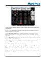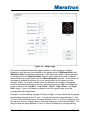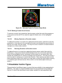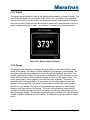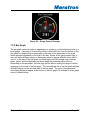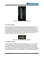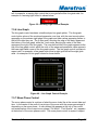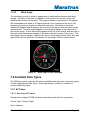
1
®
N2KView
Vessel Monitoring and Control
System
User’s Manual
Revision 1.0
Copyright © 2007 Maretron, LLP All Rights Reserved
Maretron, LLP
9014 N. 23rd Ave #10
Phoenix, AZ 85021-7850
http://www.maretron.com
Maretron Manual Part #: M001401
Revision 1.0
Page 1
®
Revision History
Rev.
1.0
Description
Original document.
Revision 1.0
Page 2
®
Table of Contents
1 2 3 Introduction .............................................................................................................. 8 Software Version ...................................................................................................... 8 Prerequisites ............................................................................................................ 8 3.1 N2KView ............................................................................................................ 8 3.2 N2KServer.......................................................................................................... 9 4 N2KView System Features ...................................................................................... 9 5 Quick Install.............................................................................................................. 9 5.1 Unpack the Box ................................................................................................ 10 5.2 Install N2KServer ............................................................................................. 10 5.3 Run N2KServer ................................................................................................ 15 5.4 Install N2KView ................................................................................................ 16 5.5 Run N2KView ................................................................................................... 21 6 General Concepts .................................................................................................. 23 6.1 Client/Server Architecture ................................................................................ 23 6.2 TCP/IP Networks .............................................................................................. 24 6.3 NAT (Network Address Translation) ................................................................. 24 6.4 Static and Dynamic IP Addressing ................................................................... 25 6.5 Software Firewall Configuration ....................................................................... 25 6.6 Data Security and Encryption ........................................................................... 25 6.7 NMEA 2000 Considerations ............................................................................. 26 6.7.1 Device Instancing ...................................................................................... 26 6.7.2 Data Instancing .......................................................................................... 27 6.7.3 Data Source Types .................................................................................... 27 6.7.4 Sensor Selection ....................................................................................... 27 7 N2KView ................................................................................................................ 28 7.1 General Concepts ............................................................................................ 28 7.1.1 Touch Screen Operation............................................................................ 28 7.1.2 Parameters ................................................................................................ 28 7.1.3 Controls ..................................................................................................... 28 7.1.4 Favorite Screens and Parameter Display .................................................. 28 7.1.5 Grid Layout Concepts ................................................................................ 29 7.1.6 Hardware License Key .............................................................................. 29 7.2 Using N2KView ................................................................................................ 29 7.2.1 The Opening Screen ................................................................................. 29 7.2.2 The Operational Mode Screen................................................................... 30 7.3 Operation ......................................................................................................... 31 7.3.1 Changing Between Favorite screens ......................................................... 31 7.3.2 Entering Configuration Mode ..................................................................... 32 7.3.3 Switching Between Day and Night Mode ................................................... 32 7.3.4 Switching Between Windowed and Full-Screen Configurations ................ 32 7.3.5 Minimizing N2KView .................................................................................. 32 Revision 1.0
Page 3
®
7.3.6 Terminating N2KView ................................................................................ 32 7.4 Configuration .................................................................................................... 33 7.4.1 Displaying Screen Tabs ............................................................................. 33 7.4.2 About Tab .................................................................................................. 33 7.4.3 Password Tab............................................................................................ 34 7.4.4 Connection Tab ......................................................................................... 35 7.4.5 Units Setup ................................................................................................ 36 7.4.6 Screen Setup ............................................................................................. 38 7.5 Available Control Types ................................................................................... 51 7.5.1 Digital......................................................................................................... 52 7.5.2 Gauge ........................................................................................................ 52 7.5.3 Bar Graph .................................................................................................. 53 7.5.4 Rocker Switch ............................................................................................ 54 7.5.5 Warning Light ............................................................................................ 54 7.5.6 Line Graph ................................................................................................. 55 7.5.7 Moon Phase Control .................................................................................. 55 7.5.8 North Up Rose ........................................................................................... 56 7.5.9 Course Up Rose ........................................................................................ 57 7.5.10 Cardinal ..................................................................................................... 57 7.5.11 GPS Status ................................................................................................ 58 7.5.12 Rudder Angle............................................................................................. 59 7.5.13 Wind Angle ................................................................................................ 60 7.6 Available Data Types ....................................................................................... 60 7.6.1 AC Power .................................................................................................. 60 7.6.2 DC Power .................................................................................................. 61 7.6.3 Depth ......................................................................................................... 63 7.6.4 Electrical Distribution ................................................................................. 63 7.6.5 Engine ....................................................................................................... 64 7.6.6 Engine Warning ......................................................................................... 68 7.6.7 Environment .............................................................................................. 75 7.6.8 GPS ........................................................................................................... 78 7.6.9 Heading ..................................................................................................... 79 7.6.10 Navigation.................................................................................................. 79 7.6.11 Rudder ....................................................................................................... 82 7.6.12 Speed/Distance ......................................................................................... 82 7.6.13 Tank .......................................................................................................... 83 7.6.14 Time/Date .................................................................................................. 85 7.6.15 Transmission ............................................................................................. 87 7.6.16 Trans. Warning .......................................................................................... 87 7.6.17 Vessel ........................................................................................................ 89 7.6.18 Wind .......................................................................................................... 89 8 N2KServer.............................................................................................................. 91 8.1 N2KServer Components .................................................................................. 91 8.1.1 N2KServer Windows Service..................................................................... 91 8.1.2 N2KServer Service Manager ..................................................................... 91 Revision 1.0
Page 4
®
8.1.3 Minimizing N2KServer Service Manager ................................................... 93 8.1.4 Terminating N2KView ................................................................................ 93 8.1.5 Security and User Accounts ...................................................................... 94 9 Troubleshooting ..................................................................................................... 94 10 Technical Support ............................................................................................... 97 11 Maretron Software License Agreement ............................................................... 98 Revision 1.0
Page 5
®
Table of Figures
Figure 1 – Maretron N2KServer Setup Wizard Welcome Page ..................................... 11 Figure 2 –License Agreement Page .............................................................................. 11 Figure 3 –Select Destination Location Page ................................................................. 12 Figure 4 –Select Additional Tasks Page........................................................................ 13 Figure 5 – N2KServer Installation Wizard Ready to Install Page .................................. 13 Figure 6 – N2KServer Installation Wizard Passwords Page.......................................... 14 Figure 7 – N2KServer Installation Wizard Completion Page ......................................... 14 Figure 8 – N2KServer Service Manager Window .......................................................... 15 Figure 9 – Welcome Page ............................................................................................. 17 Figure 10 – N2KView Installation Wizard License Agreement Page ............................. 18 Figure 11 –Select Destination Location Page ............................................................... 18 Figure 12 – Select Additional Tasks Page..................................................................... 19 Figure 13 – Ready to Install Page ................................................................................. 19 Figure 14 – Licensing Page........................................................................................... 20 Figure 15 – Maretron N2KView Installation Wizard Completion Page .......................... 21 Figure 16 – N2KView Window with Tabs Displayed ...................................................... 22 Figure 17 – N2KView Opening Screen.......................................................................... 30 Figure 18 – N2KView Operational Mode Screen ........................................................... 31 Figure 32 – N2KView Screen Tabs ............................................................................... 33 Figure 33 – About Window ............................................................................................ 34 Figure 34 – Change Password Window ........................................................................ 35 Figure 35 – Server Connection Settings Window .......................................................... 35 Figure 36 – Units Setup Window ................................................................................... 36 Figure 37 – Screens Setup Window .............................................................................. 39 Figure 38 – Parameter Page of Control Configuration Wizard ...................................... 41 Figure 39 – Source Page of Control Configuration Wizard............................................ 42 Figure 40 – Control Page .............................................................................................. 43 Figure 41 – Instance Page ............................................................................................ 44 Figure 42 – Indicator Page ............................................................................................ 45 Figure 43 – Gauge Page ............................................................................................... 46 Figure 44 – Gauge Configuration Example ................................................................... 47 Figure 45 – Bar Graph Page ......................................................................................... 48 Figure 46 – Completion Page ........................................................................................ 50 Figure 47 – Selected Control in Screens Setup Mode................................................... 51 Figure 19 – Digital Control Example .............................................................................. 52 Figure 20 – Gauge Control Example ............................................................................. 53 Figure 21 – Bar Graph Control Example ....................................................................... 54 Figure 22 – Rocker Switch Control Example ................................................................. 54 Figure 23 – Warning Light Control Example.................................................................. 55 Figure 24 – Line Graph Control Example ...................................................................... 55 Figure 25 – Moon Phase Control Example.................................................................... 56 Figure 26 – North Up Control Example ......................................................................... 56 Figure 27 – Course Up Control Example....................................................................... 57 Revision 1.0
Page 6
®
Figure 28 – Cardinal Control Example .......................................................................... 58 Figure 29 – GPS Status Control Example ..................................................................... 59 Figure 30 – Rudder Angle Control Example .................................................................. 59 Figure 31 – Wind Angle Control Example ..................................................................... 60 Revision 1.0
Page 7
®
1 Introduction
Thank you for purchasing the Maretron N2KView Vessel Monitoring and Control
System. The N2KView system enables you to have complete visibility to the state of
your vessel from anywhere on your vessel or anywhere in the world with Internet
access. This manual guides you through the installation, configuration, and usage of
the N2KView system. Please read it carefully and follow the instructions closely when
installing, configuring, and using your N2KView System.
2 Software Version
This manual corresponds to N2KView Version 2.0 and N2KServer Version 2.0
3 Prerequisites
3.1 N2KView
The following requirements must be met in order to successfully run N2KView:
•
Operating System: Windows XP Home Edition/Professional, or Microsoft Vista
•
CPU: Minimum Pentium® 4 or Equivalent, Recommended Pentium® 4, 3.0 GHz
•
Memory: Minimum 512 MB RAM, Recommended 1 GB RAM
•
Hard Drive Space: 40 MB
•
CD-ROM or DVD Drive
•
Video Card: Minimum 128 MB memory, Recommended 256 MB
•
USB Ports: One 1.1 or 2.0 compatible port
•
Network Connection: 10BASE-T or 100BASE-TX, or 802.11a/b/g
•
Display: Minimum 1024x768 Resolution, 32-Bit Color Video
•
Multiple Monitor Support: Dedicated Video Cards with Minimum 64 MB memory
per monitor
•
Touch Screen or Mouse with Windows Compatible Driver
•
Keyboard (for assigning user-defined titles to controls, entering passwords and
connection information)
Revision 1.0
Page 8
®
3.2 N2KServer
The following requirements must be met in order to successfully run N2KServer:
•
Operating System: Windows XP Home Edition/Professional, or Microsoft
Vista
•
CPU: Minimum Pentium® 4 or Equivalent, Recommended Pentium® 4, 3.0
GHz
•
Memory: Minimum 512 MB RAM, Recommended 1 GB RAM
•
Hard Drive Space: 40 MB
•
CD-ROM or DVD Drive
•
Video Card: Minimum 128 MB memory, Recommended 256 MB
•
USB Ports: Two 1.1 or 2.0 compatible ports
•
Network Connection: 10BASE-T or 100BASE-TX, or 802.11a/b/g
•
A NMEA 2000 gateway Currently, compatible gateways include the following:
•
Maretron USB100 with firmware revision 1.7.1 or greater (contact Maretron
for any necessary firmware updates) with a Maretron USB100 Windows driver
dated 8/3/2007, version 1.0.0.0, or a more recent revision. This version of the
driver is installed by default by the Maretron N2KServer Setup Wizard, but
you may need to manually update the USB100 driver using the Windows
Device Manager in order to use the updated driver if you are using a NMEA
2000 gateway you installed previously to installing N2KServer. N2KServer
can operate with earlier versions of USB100 drivers, but will not automatically
recover when NMEA 2000 power is lost or when the USB gateway is
unplugged from the computer and then plugged in again.
•
Mouse
•
Keyboard
4 N2KView System Features
5 Quick Install
This section will help you install the software for the first time and get it running as
quickly as possible with basic settings.
Revision 1.0
Page 9
®
5.1 Unpack the Box
The N2KView System is sold in two configurations:
1) N2KServer and N2KView
a. N2KServer Software CD-ROM
i. Installer for N2KServer
ii. Installer for Adobe Acrobat Reader
iii. N2KServer Quick Install Guide PDF file
iv. N2KView System User’s Manual PDF file
b. N2KServer Hardware License Key
c. N2KServer Quick Setup Guide
2) N2KView only
a. N2KView Software CD-ROM
i. Installer for N2KView
ii. Installer for Adobe Acrobat Reader
iii. N2KView Quick Install Guide PDF file
iv. N2KView System User’s Manual PDF file
b. N2KView Hardware License Key
c. N2KView Quick Setup Guide
5.2 Install N2KServer
NOTE: Since the N2KServer Setup Wizard installs device drivers for the Hardware
License Keys and the NMEA 2000 gateway, the setup wizard must be run from an
account with administrator privileges, as those privileges are required by Windows in
order to install device drivers.
a.
Insert the N2KServer CD-ROM into your computer’s CD-ROM drive.
Revision 1.0
Page 10
®
Figure 1 – Maretron N2KServer Setup Wizard Welcome Page
b.
The installer will automatically start unless you have disabled AutoPlay on the
CD-ROM drive. If this is the case, double-click on the CD-ROM drive in
Windows Explorer to start the installer. The Welcome screen will be shown
next. Please press “Next >“ to continue the installation.
Figure 2 –License Agreement Page
Revision 1.0
Page 11
®
c.
The “License Agreement” screen will be shown next. Please read the
license agreement carefully. If you agree with the terms of the license
agreement, please select “I accept the agreement” and then click “Next >“ to
continue the installation. If you select “I do not accept the agreement”, the
installer will terminate without installing the software.
Figure 3 –Select Destination Location Page
d.
The “Select Destination Location” screen will display next. If you wish to
install to a different location from the default shown, enter it in the text box or
click the “Browse…” button to navigate to your desired installation directory.
Click “Next >“ to continue.
Revision 1.0
Page 12
®
Figure 4 –Select Additional Tasks Page
e.
The “Select Additional Tasks” screen will display next. Select the
appropriate checkboxes to install shortcuts for the program on the desktop or
the quick launch bar. Click “Next >“ to continue.
Figure 5 – N2KServer Installation Wizard Ready to Install Page
f.
The “Ready to Install” screen will display next. Please verify that all the
information on this screen is as desired. Click “Next >“ to continue.
Revision 1.0
Page 13
®
Figure 6 – N2KServer Installation Wizard Passwords Page
g.
The “Passwords” screen will display next. You must choose a password for
N2KServer. This will allow only your N2KView programs with the correct
password to view your network data. Please choose a password and save it
in a safe place. The password cannot be recovered from N2KServer, so if
you misplace or forget this password, you will need to reset it. Click “Next >“
to continue.
Figure 7 – N2KServer Installation Wizard Completion Page
Revision 1.0
Page 14
®
The installation is now complete. If you wish to configure the N2KServer software at
this time, select the “Run N2KServer Service Manager” checkbox. You also have the
opportunity to register your software at this time. Please make sure to register your
software in order to qualify for technical assistance.
5.3 Run N2KServer
Note: Before running N2KServer, please make sure your USB gateway is connected to
a USB port on your computer and also to a powered NMEA 2000 network.
The N2KServer Service Manager program is used to start, stop, and configure
N2KServer. The service manager’s dialog box, shown below, has the following
sections:
Figure 8 – N2KServer Service Manager Window
General: This sections shows whether the N2KServer is running, as well as the serial
number of the N2KServer Hardware License Key (dongle).
Statistics: This section shows the number of N2KView clients currently connected, as
well as the number of messages transmitted to and received from the clients. The
“Start” button is used to start the N2KServer, and the “Stop” button is used to stop the
N2KServer.
Revision 1.0
Page 15
®
NMEA 2000 Data Selection: There are two choices for data: “Simulated Data” is only
to be used for product demonstration and testing. The N2KServer will output a
selection of simulated NMEA 2000 messages. “Live Network Data” causes the
N2KServer to output data from the NMEA 2000 gateway which is selected in the
“Gateway Serial Port” dropdown list. If this list is empty, please ensure that the USB
gateway is connected.
Automatic Startup: If the “Start N2KServer When Windows Starts” box is checked,
then N2KServer will run whenever the computer is turned on, regardless of whether
anyone has logged in to the computer. If this box is cleared, then you must manually
start the N2KServer Service Manager and click the “Start” button in order to start the
N2KServer.
Security: You must enter a password into the “Server Password” text box, and then
click “Set”, to ensure that only your N2KView software (which must be programmed with
the same password) can view your network data.
Steps to configure and start N2KServer the first time:
1.
Click the “Live Network Data” radio button.
2.
Select an NMEA 2000 gateway from the “Gateway Serial Port” dropdown list.
3.
Check the “Start N2KServer When Windows Starts” checkbox.
4.
Select a password and enter it into the “Server Password” text box, then click
the “Set” button.
5.
Click the “Start” button.
N2KServer is now ready to accept connections and send NMEA 2000 data to N2KView
clients on the network. Note the IP address of this computer and proceed with
N2KView installation.
5.4 Install N2KView
NOTE: Since the N2KView Setup Wizard installs device drivers for the Hardware
License Keys, the setup wizard must be run from an account with administrator
privileges, as those privileges are required by Windows in order to install device drivers.
a. Insert the N2KView CD-ROM into your computer’s CD-ROM drive.
b. The installer will automatically start unless you have disabled AutoPlay on the
CD-ROM drive. If this is the case, double-click on the CD-ROM drive in Windows
Revision 1.0
Page 16
®
Explorer to start the installer. The Welcome screen will be shown next. Please
press “Next >“ to continue the installation.
Figure 9 – Welcome Page
c. The “License Agreement” screen will be shown next. Please read the license
agreement carefully. If you agree with the terms of the license agreement, please
select “I accept the agreement” and then click “Next >“ to continue the
installation. If you select “I do not accept the agreement”, the installer will
terminate without installing the software.
Revision 1.0
Page 17
®
Figure 10 – N2KView Installation Wizard License Agreement Page
d. The “Select Destination Location” screen will display next. If you wish to install
to a different location from the default shown, enter it in the text box or click the
“Browse…” button to navigate to your desired installation directory. Click “Next >“
to continue.
Figure 11 –Select Destination Location Page
Revision 1.0
Page 18
®
e. The “Select Additional Tasks” screen will display next. Select the appropriate
checkboxes to install shortcuts for the program on the desktop or the quick
launch bar. Click “Next >“ to continue.
Figure 12 – Select Additional Tasks Page
f. The “Ready to Install” screen will display next. Please verify that all the
information on this screen is as desired. Click “Next >“ to continue.
Figure 13 – Ready to Install Page
Revision 1.0
Page 19
®
g. The “Licensing” screen will display next. At this time, please plug the blue
N2KView Hardware License Key (dongle) into a USB port on your computer.
Figure 14 – Licensing Page
h. The installation is now complete. To run the N2KView software, click on the
N2KView icon in the Start Menu, desktop, or Quick Launch bar. You have the
opportunity to register your software at this time. Please make sure to register
your software in order to qualify for technical assistance.
Revision 1.0
Page 20
®
Figure 15 – Maretron N2KView Installation Wizard Completion Page
5.5 Run N2KView
Note: Before running N2KView, please make sure N2KServer is running either on the
same computer or on a different computer whose IP address is accessible from this
computer. The first time you run N2KView, you must configure the connection to enable
N2KView to receive information from an instance of N2KServer. This is done through
the following steps:
Revision 1.0
Page 21
®
Figure 16 – N2KView Window with Tabs Displayed
a. Click anywhere inside the N2KView screen to display the screen tabs as shown in
Figure 8 above.
b. Click on the “Connection” screen tab on the right side of the N2KView screen to
display the Connection dialog box.
c. In the “Server Address” text box, enter the IP address of the computer running
N2KServer. If N2KServer is running on this computer, leave at the initial setting of
“127.0.0.1”.
d. In the “Server Password” text box, enter the same server password that you entered
into the N2KServer Service Manager.
e. Click “OK”. In a few seconds, N2KView should begin displaying data from the
connected N2KServer.
If no data is displayed, please check the following:
1. Make sure the “Server Password” entered in N2KView matches the “Server
Password” entered into the N2KServer Service Manager on the computer running
N2KServer.
2. Make sure the “Server Address” matches the IP address of the computer running
N2KServer.
Revision 1.0
Page 22
®
3. Make sure you have appropriate instruments on the NMEA 2000 network to provide
the data you are trying to view on the N2KView screen. (To test the network connection
between N2KView and the N2KServer, you may wish to run N2KServer in “Simulated
Data” mode.)
Along the top of the screen are the user-defined screens. Click on a screen tab to
display the corresponding screen. Use the left and right arrow keys to cycle between the
different user-defined screens.
Along the right-hand side of the screen are the standard screen tabs:
Night Mode: Switches N2KView in and out of Night Mode (you may also use the “N”
key)
Screens Setup: This tab allows you to change, add, or delete user-defined screens.
Connection: Allows you to set the IP Address and Server Password for the N2KServer
Units Setup: Allows you to configure measurement units for displayed parameters
Password: Allows you to password-protect the N2KView configuration. Note: this is
different from the “Server Password” entered in the “Connection” dialog box.
About: Displays software version and Hardware License Key serial number.
6 General Concepts
6.1 Client/Server Architecture
The N2KView Vessel Monitoring and Control System is based on a client/server
architecture. In this context, a server is defined as a component that provides services
over a network and a client is defined as a component that requests and uses those
services.
In the N2KView System, there is one server and one or more clients. The server
component is implemented by the N2KServer software, and the client components are
implemented by the N2KView software. The service offered by the server to the clients
is access to the NMEA 2000 network data that the server receives from the NMEA 2000
network via its NMEA 2000 gateway. The network over which this service is offered is
implemented as a TCP/IP (Transmission Control Protocol/Internet Protocol) network,
which is discussed in the next section.
Revision 1.0
Page 23
®
6.2 TCP/IP Networks
The networking protocol that is used for the communication between the server and
clients in the N2KView system is the TCP/IP protocol. This protocol is used by the
World Wide Web, FTP (File Transfer Protocol), and many others of the most popular
applications on the Internet. The TCP/IP connection can be made over an Ethernet
connection, a Wi-Fi connection, cellular phone data connection, and many other types
of media. In fact, a single packet of TCP/IP data may traverse multiple types of media
on its journey. The TCP/IP protocol is natively supported by Microsoft Windows XP and
Microsoft Windows Vista, as well as Internet-connected cellular phones.
Each computer on a TCP/IP network is identified by an IP address unique to that
network. An IP address consists of four numbers, each ranging between 0 and 255,
separated by periods. This is referred to a dotted decimal notation. Examples of IP
addresses in this format are 10.0.0.1, and 62.12.31.188.
6.3 NAT (Network Address Translation)
If you wish to use N2KView to view data from an N2KServer on a separate network
through an Internet connection, please read this section. If your N2KServer and
N2KView computers are on the same network, you may skip this section.
In the early days of the Internet, each computer connected to the Internet had its own IP
address.
With the explosive growth of the Internet, the number of distinct IP addresses is starting
to run out. It is no longer practical for an Internet Service Provider (ISP) to provide its
customers with individual IP addresses for each component the customer wishes to
connect to the Internet. Rather, the ISP normally assigns each customer a single IP
address, and a router implementing Network Address Translation (NAT) is connected to
the Internet connection (sometimes referred to as the Wide Area Network, or WAN,
connection) on one side, and to the Local Area Network, or LAN, on the other side.
Each computer on the LAN side of the connection will be assigned its own IP address,
typically in the ranges 192.168.x.x, 10.x.x.x, and 172.16.x.x through 172.31.x.x, where x
can be any number in the range 0-255. The WAN connection will be assigned a single
IP address by the ISP.
Generally, network address translation is performed by a router that is connected to the
Internet via a Cable or DSL connection in the WAN side, and to the local area network
(LAN) via Ethernet or Wi-Fi connections. In order to access an N2KServer on the local
area network from an N2KView outside of the LAN. You must configure the router to
allow incoming connections on port 6544 and to forward these connections to the IP
address of the N2KServer computer. Consult the documentation that came with your
router for details.
Revision 1.0
Page 24
®
6.4 Static and Dynamic IP Addressing
If you wish to use N2KView to view data from an N2KServer on a separate network
through an Internet connection, please read this section. If your N2KServer and
N2KView computers are on the same network, you may skip this section.
If you request a Static IP Address from your ISP when you set up your Internet
connection, the WAN IP address will always be the same. If you didn’t make this
request, your ISP will assign you a Dynamic IP Address, which may actually change
from time to time. In this way, the ISP only needs to have enough addresses to cover
its customers who are connected to the Internet at any given time. If you stop or lose
your Internet connection, your Dynamic IP address will be released and may be
reassigned to someone else.
If you wish to connect to an N2KServer from off your vessel’s local network via an
Internet connection, you have two choices. First, you can request a static IP address
from the ISP for your vessel; secondly, you may register your N2KServer’s IP address
with a “dynamic DNS service”, such as the ones offered freely by www.dyndns.org,
among others. Please visit their websites for more information on how dynamic DNS
services operate.
6.5 Software Firewall Configuration
If you wish to run N2KView and N2KServer on two separate computers and are running
a software firewall product other than Windows Firewall, please read this section.
Otherwise, you may skip this section.
A firewall is a component of hardware or software designed to protect your computer
from unfettered access from the Internet. There are two kinds of firewalls: software and
hardware. A software firewall is a component such as Windows Firewall or Norton
Internet Security. A major function of these programs is to allow your computer to
initiate connections out onto the Internet, but to block your computer from receiving
incoming connections from the Internet. If you wish to be able to view your vessel’s
data from another computer, your N2KServer computer’s software firewall must be
configured to allow incoming connections from N2KView clients. The N2KServer makes
these adjustments to the Windows Firewall software when it is installed. If you are
running firewall software from another vendor, you may have to configure your firewall
software to allow this incoming TCP protocol connection on port 6544.
6.6 Data Security and Encryption
Making your vessel’s data available over local networks or the internet presents multiple
security concerns. First, it is desirable to keep anyone from viewing your vessel’s data
without authorization. Second, and more important, it is imperative that no unauthorized
persons be able to place data onto your vessel’s NMEA 2000 network.
Revision 1.0
Page 25
®
The N2KView system protects your vessel’s data with multiple levels of protection.
First, any data that passes between the N2KServer server component and any
N2KView client components is protected using industry-standard SSL encryption. This
encryption standard is widely used to protect financial information on the internet. Each
communication session negotiates a random encryption key every time a connection is
established. This makes the data secure over public and private Wi-Fi networks, as
well as the internet. Each N2KView client that wishes to connect to an N2KServer
server component must authenticate itself by means of a server password. The server
password is transmitted by the N2KView client to the N2KServer server over the
encrypted communication link. The N2KServer compares the server password to the
one it was programmed with. Only if the server password received from the client
matches the server’s stored password is the client granted access to the NMEA 2000
network data.
6.7 NMEA 2000 Considerations
This section describes some requirements for the NMEA 2000 networks to be
monitored with N2KView.
6.7.1 Device Instancing
The one aspect of NMEA 2000 that you need to be aware of as a user of N2KView is
the concept of device instances. The device instance is an eight-bit value (ranging
between 0 and 255) that every NMEA 2000 device transmits when it joins the bus and
upon request thereafter. This becomes important when you have multiple devices that
transmit the same data. It is possible, for example, to have two GPS antennas on a
vessel, with one serving as a primary antenna and others serving as backups. If this is
so, the NMEA 2000 standard requires that the two different antennas have two different
device instances. If you are using a certified NMEA 2000 product, the NMEA 2000
standard requires that a user be able to program the device instance in each product.
Consult the device documentation or contact your device manufacturer in order to
determine how to program the instance into a particular device.
N2KView uses the draft device instancing standard under consideration by the NMEA
2000 working group. In this standard, the device instance is programmed as an eightbit value with the upper five bits, also known as the Upper Device Instance, indicating
the location of the parameter the device is measuring (should be different for any two
devices transmitting different data, for example a port fuel tank level and a starboard
tank level) and the lower three bits, also known as the Lower Device Instance, indicating
the priority level of the device to allow a receiver to prioritize data from multiple devices
transmitting the same information (these are used to distinguish between two devices
transmitting redundant copies of the same measurement, for example, two GPS
antennas, one serving as the primary unit and the other serving as a secondary backup
unit). For the Lower Device Instance, a value of 0 indicates the highest priority and a
value of 7 indicates the lowest priority.
Revision 1.0
Page 26
®
The eight-bit device instance is constructed from the upper and lower device instances
as follows:
device_instance = upper_device_instance * 8 + lower_device_instance,
where:
upper_device_instance identifies the entity on which the measurement is being
performed, and
lower_device_instance identifies the priority of this measuring device relative to
others measuring the same value on the same entity.
6.7.2 Data Instancing
Certain NMEA messages, such as those from batteries, tanks, engines, and
transmissions, have data instances embedded in the messages. These data instances
are used, if programmed, to relate data to specific data sources. Data instances are
also required by the NMEA 2000 standard to be field-programmable, so please consult
your device’s documentation for details on how to program this value.
In order to support “plug-and-play” operation, if N2KView receives the same data from
multiple devices that have the same device instance programmed, it will “lock on” to the
first unit it receives data from until either 1) it stops receiving data from the first unit, in
which case it will switch to the second unit, or 2) it starts receiving data from another
unit with higher priority, in which case it will transmit the data from that unit.
6.7.3 Data Source Types
The NMEA 2000 standard provides for the transmission of data from similar devices,
but for different sources. For example, the NMEA 2000 standard supports six different
types of fluid tanks: Fuel, Oil, Live Well, Fresh Water, Waste Water, and Black Water. It
further supports up to sixteen tanks of each of these types. It is the responsibility of the
person installing the NMEA 2000 system to ensure that each tank level sender is
programmed with the appropriate fluid type and tank instance.
6.7.4 Sensor Selection
Of course, one key to making the N2KView System work is making sure that your
NMEA 2000 network has the proper sensors to provide the information you wish to
monitor using N2KView. Section 7.3 on page 60 contains a listing of all of the data
types that can be monitored using N2KView. One of the details provided for each data
type is a list of the Maretron components that can provide that data. Please note that
certain data types require multiple sensors of different types.
Revision 1.0
Page 27
®
7 N2KView
This section details the configuration and operation of the N2KView client component of
the N2KView System.
7.1 General Concepts
7.1.1 Touch Screen Operation
N2KView was designed so that all functions in operational mode can be performed with
either a mouse or a touch screen. It is still required to have a mouse and a keyboard for
performing configuration of N2KView.
7.1.2 Parameters
The key concept of N2KView is the display of parameters. A parameter is a piece of
information about some function of the vessel. The parameter is defined by a particular
data type, such as engine speed or barometric pressure, and possibly also by a
particular instance of that data type; for example, the engine speed for the port engine.
All of the available data types that N2KView can display are listed in Section 7.6 on
page 60.
7.1.3 Controls
Each parameter may be displayed by a control. The control is a graphical display that is
generally dedicated to the display of the value of a certain parameter. Examples of
controls include the digital display, a gauge, and a bar graph. A complete listing of
available control types appears in Section 7.5on page 51. If data is not available for a
control, the control will appear dimmed on the operational mode screen and will display
no values.
7.1.4 Favorite Screens and Parameter Display
N2KView employs the concept of favorite screens. These screens are usercustomizable to display a group of controls which generally will display related
parameters, such as engine data, navigation data, tank levels, and so on. N2KView
comes with eight pre-defined favorite screens: Engines, DC Systems, AC Systems,
Navigation, Environment, Tanks, and Miscellaneous. You may use these screens as
provided, modify them, or delete them and create your own screens from scratch.
There is no fixed limit on the number of favorite screens you can create.
Revision 1.0
Page 28
®
7.1.5 Grid Layout Concepts
A favorite screen in N2KView is laid out on a square grid system. When you create a
favorite screen, you choose the number of square grids wide and high the favorite
screen is. When the favorite screen is displayed in normal operating mode, it expands
to fill the N2KView window as much as possible (or the entire computer screen if
operating in full screen mode). You should choose a number of grids that is fairly small.
When you create or move controls, they snap to the grid intersections, so the fewer
grids you have in your layout, the easier it is to place and align controls. It is also
important to choose a number of grids that matches the aspect ratio of the window in
which you plan to run N2KView, in order to minimize blank space in the N2KView
window. For example, if you are creating a favorite screen that is designed to run in full
screen mode on a computer with a typical 4:3 aspect ratio, you may wish to make the
favorite screen 40 grids wide by 30 grids high, so that the computer screen is
completely filled when N2KView is operating in full-screen mode. However, you may
wish to run N2KView simultaneously with a chart plotting program, letting the chart
plotting program occupy the left half of the computer screen and letting N2KView
occupy the right half of the computer screen. Choosing a favorite screen size of 20
grids wide and 30 grids high would allow you to completely fill this window with controls.
If you choose a favorite screen size and decide later that you wish you had chosen
different height and width values, you can always change these at any time (see
Section 6.4.5.6 on page 40 for details).
7.1.6 Hardware License Key
The licensing of the N2KView Vessel Monitoring and Control System is controlled by the
use of Hardware License Keys, which are often referred to by the term “dongles”.
These Hardware License Keys must be installed into a USB port on any computer
running either the N2KServer component of the N2KView component. The software
test for the presence of the appropriate hardware license key before it begins operation.
If the hardware license key is not detected, the software will not run. After the software
starts running, it continually tests for the presence of the hardware license key. If the
hardware license key is removed from the computer, the software will stop functioning
and will display a dialog box asking the user to reconnect the hardware license key to
the system.
7.2 Using N2KView
This section describes how to operate the N2KView program after it is installed.
7.2.1 The Opening Screen
When you start N2KView, the program will display an opening screen (shown in Figure
17 below) listing the title and software version of the program, and asking you to accept
the following agreement:
Revision 1.0
Page 29
®
WARNING: By pressing “Accept”, you acknowledge that while Maretron
products are designed to be accurate and reliable, they should be used
only as aids to navigation and vessel monitoring and not as a replacement
for traditional aids and techniques.
If you accept the warning, press the “Accept” button and the program will change into
operational mode. If you do not accept the warning, press the “Exit” button and the
program will terminate.
Figure 17 – N2KView Opening Screen
7.2.2 The Operational Mode Screen
Once you have accepted the warning in the opening screen, it closes and the
operational mode screen appears. An example of an operational mode screen is shown
below.
Revision 1.0
Page 30
®
Figure 18 – N2KView Operational Mode Screen
7.3 Operation
This section describes the activities that you may wish to perform with N2KView once it
is fully configured and in operation.
7.3.1 Changing Between Favorite screens
You may change between favorite screens in one of two ways. First, press on the
N2KView window to display the tabs, and then press the tab along the top of the
N2KView window for the favorite screen you wish to display. Second, you can cycle
through the list of defined favorite screens by using the left-arrow and right-arrow keys
on the computer’s keyboard.
Revision 1.0
Page 31
®
7.3.2 Entering Configuration Mode
In operational mode, press anywhere on the N2KView window to display the screen
tabs. While the screen tabs along the top of the screen display your defined favorite
screens, the screen tabs along the right-hand edge of the screen perform various
configuration functions. Section 7.4 on page 33 describes these configuration tabs and
the functions they perform.
7.3.3 Switching Between Day and Night Mode
N2KView supports a Night Mode to enable viewing in dark conditions. In this mode, all
colors are converted to muted red tones so that you can view the favorite screens
without reducing your night vision. You may enter Night Mode by pressing the “Night
Mode” tab. In Night Mode, this tab changes to read “Day Mode”, which you may press
to exit Night Mode and return to Day Mode. You may also press the “N” key to toggle
between day and night modes.
7.3.4 Switching Between Windowed and Full-Screen Configurations
You may change the viewing mode of N2KView to take up the entire computer screen.
Pressing the “F11” key will toggle N2KView between full-screen mode and windowed
mode. In full-screen mode, you may wish to hide the Windows taskbar so that the
N2KView window is the only visible element on the computer screen. You can do this
by right-clicking on the Windows taskbar, selecting ‘Properties” from the pop-up menu,
checking the “Auto-hide the taskbar” box on the “Taskbar” tab of the “Taskbar and
Start Menu Properties” dialog box that displays, then clicking on the “OK” button. The
taskbar will then disappear from view but will reappear whenever you move the mouse
to the bottom edge of the computer screen.
7.3.5 Minimizing N2KView
To minimize N2KView to the taskbar, switch N2KView into windowed mode if it not
already there (see Section 7.5.3 for details), and then click on the minimize button (with
a straight horizontal line in the bottom of the button), third from the right in the group of
system buttons in the extreme upper right hand corner of the window, at the right edge
of the Windows title bar.
7.3.6 Terminating N2KView
To terminate the N2KView program, switch N2KView into windowed mode if it not
already there (see Section 7.5.3 for details), and then click on the red “X” in the extreme
upper right hand corner of the window, at the right edge of the Windows title bar.
You may also terminate N2KView using the “Alt-F4” key combination in full-screen
mode, or in windowed mode when N2KView is the active window.
Revision 1.0
Page 32
®
7.4 Configuration
7.4.1 Displaying Screen Tabs
After you close the opening screen, the N2KView software enters normal operating
mode. You may display the screen tabs at any time by pressing anywhere on the
screen. The screen tabs used for N2KView configuration appear along the right side of
the screen. A display of the screen tabs is shown below.
Figure 19 – N2KView Screen Tabs
7.4.2 About Tab
Pressing the “About” tab will cause the “About” dialog box to be displayed, which will
display information about N2KView including its version number and serial number, both
of which are necessary in the event you need to contact Maretron for technical support.
Press the OK button to close the dialog box. A screenshot of the “About” window is
shown below.
Revision 1.0
Page 33
®
Figure 20 – About Window
7.4.3 Password Tab
N2KView allows you to set a password to protect your configuration from inadvertent
changes. In order to set or change the password, press the “Password” tab, which will
cause the “Change Password” dialog box to be displayed. If you are entering a new
configuration password, leave the “Old Password” text box blank. If you are changing
a configuration password, you must enter the existing password in the “Old Password”
text box. Enter the new desired password into the “New Password” text box, and enter
it again into the “Repeat New Password” text box. If you wish to remove the
configuration password, simply leave the “New Password” and “Repeat New
Password” text boxes blank. Once you are satisfied with the values you have entered,
click the “OK” button to apply the changes you have made. A screenshot of the
“Change Password” window is shown below.
Revision 1.0
Page 34
®
Figure 21 – Change Password Window
7.4.4 Connection Tab
Pressing the “Connection” tab causes the “Server Connection Settings” window to be
displayed. This window allows you to configure the parameters that are used when
connecting to the N2KServer. An example of the “Server Connection Settings”
window is shown below.
Figure 22 – Server Connection Settings Window
7.4.4.1 Host
Please set this field to the IP address of the N2KServer you wish to connect to
7.4.4.2 Port
Please leave this field at the default setting of 6544
Revision 1.0
Page 35
®
7.4.4.3 Enter the server password
Please set this field to the same value as you entered in the “Server Password” text
box of the N2KServer to which you are connecting. NOTE: this is different from the
configuration protection password which is changed using the “Password” tab.
7.4.5 Units Setup
Pressing the “Units Setup” tab causes the “Units Setup” window to be displayed. A
screenshot of the “Units Setup” window is shown below. The “Units Setup” menu
allows you to set the desired display units for the different parameter types supported by
N2KView. The following sections provide more detail on the individual unit settings.
Figure 23 – Units Setup Window
Revision 1.0
Page 36
®
7.4.5.1 Default Units
This section of the “Units Setup” dialog you to choose the default units which are
selected when creating controls to measure various types of parameters. You are given
the opportunity to select units other than the default units when you are creating or
modifying controls using the control configuration wizard.
7.4.5.1.1 Atmospheric Pressure
Bar, millibar, inches mercury, Kilo Pascal, Millimeters Mercury
7.4.5.1.2 Date Format
DD-MM-YYYY (31-12-2007), DD-MMM-YYYY (31-DEC-2007), MM-DD-YYYY (12-312007), MMM-DD-YYYY (DEC-31-2007)
7.4.5.1.3 Depth
Feet, Fathoms, Meters
7.4.5.1.4 Distance
Kilometers, Nautical Miles, Statute Miles
7.4.5.1.5 Fluid Pressure
Bar, Kilo Pascal, Pounds/Square Inch
7.4.5.1.6 Speed
Kilometers/Hour, Nautical Miles/Hour, Miles/Hour
7.4.5.1.7 Temperature
Degrees Celsius, Degrees Fahrenheit
7.4.5.1.8 Time Format
12 Hour, 24 Hour
7.4.5.1.9 Volume
Imperial Gallons, Liters, US Gallons
7.4.5.1.10
Wind Speed
Beaufort, Kilometers/Hour, Nautical Miles/Hour, Miles/Hour
Revision 1.0
Page 37
®
7.4.5.2 Global Settings
This section of the “Units Setup” dialog allows you to configure settings that are used
throughout the N2KView software.
7.4.5.2.1 Local Time Offset
These selection boxes allow you to configure the offset from UTC (Universal
Coordinated Time, also known as GMT, or Greenwich Mean Time). For example, if you
were in the Eastern US, you would select -4:00 during daylight savings time, and -5:00
during standard time (daylight savings not in effect). You can configure local time in
increments as small as 15 minutes.
7.4.5.2.2 Heading/Course/Bearing
This selection box allows you to decide whether headings, course, and bearing
information are displayed as true (relative to the geographic north pole) or magnetic
(relative to the magnetic north pole).
7.4.5.2.3 Wind True Vessel Referenced
“True Vessel Referenced Wind” describes the speed and direction of the wind if the
boat were “stopped”. This global setting determines whether “stopped” means relative
to a point on the ground or to the water. Powerboaters may prefer to use the “Ground”
setting of this parameter, whereas sailboaters may prefer to use the “Water” setting.
Please see Section 7.6.18 on page 89 for details of how this setting affects which
sensors are needed to produce this measurement.
7.4.6 Screen Setup
When your start N2KView for the first time, you will notice that there are eight
predefined favorite screens already set up for. You can use these favorite screens as
they are provided, modify them to suit your needs, or delete them and create your own
favorite screens.
7.4.6.1 Screens Setup Screen
This section explains each component of the “Screens Setup” window, which is shown
below.
Revision 1.0
Page 38
®
Figure 24 – Screens Setup Window
7.4.6.1.1 Screen List
The “Screen List” appears in the upper left-hand corner of the “Screens Setup”
screen. This list contains the names of all of the favorite screens you have defined. In
order to configure a particular favorite screen, select its name in the “Screen List” by
pressing on it.
7.4.6.2 Adding Screens
In order to define a new favorite screen, type the desired favorite screen name into the
“Title” text box, then enter the desired width of the favorite screen In square grids into
the “W:” text box and the desired height of the favorite screen in square grids into the
“H:” text box. Finally, press the “Add New Screen” button to add the newly defined
favorite screen to the list and display the new, empty favorite screen so that you can
begin adding controls to it.
Revision 1.0
Page 39
®
7.4.6.3 Deleting Screens
In order to remove a favorite screen from your configuration, select its name in the
“Screen List”, and then press the “Remove Screen” button.
7.4.6.4 Renaming Screens
In order to change the name of a favorite screen, select its name in the “Screen List”,
edit the favorite screen’s name in the “Title” text box under “Screen Properties” to the
desired value, and then press the “Modify This Screen” button. The favorite screen
will now appear in the screen list with the new name.
7.4.6.5 Resizing Screens
In order to change the size of a favorite screen, select its name in the “Screen List”,
and then enter the new width and/or height in square grid units into the “W:” and “H:”
textboxes, respectively. Press the “Modify This Screen” button to make the changes.
The favorite screen will now be displayed with the new grid settings. If you changed the
favorite screen to have more grids than it previously had, all of the existing controls will
appear in the upper left corner of the new favorite screen. If you changed the favorite
screen to have less grids than it previously had, then all of the controls that would fall off
the lower and/or right edges of the favorite screen with the newly defined size will be
removed from the favorite screen configuration.
7.4.6.6 Adding Controls to Screens
In order to add a control to a favorite screen, drag the mouse or your finger over the
displayed favorite screen to define the location and size of the new control. You may
not add a new control which overlaps controls that are already present. Release the
mouse button or remove your finger from the screen once you have defined the location
and size of the control shown by the highlighted grid squares. Once you have
completed defining the size and location of the new control, a control configuration
wizard appears to allow you to configure the control to display the data in the manner
you desire. At any step in the process, several buttons appear in the lower right-hand
corner of the wizard
1. “Continue”: Accept the selected values and move to the next step of the wizard
2. “Back”: Return to the previous step of the wizard
3. “Cancel”: End the wizard, abandoning all changes
4. “Finish”: End the wizard, accepting the selected values and creating the new
control or modifying the existing control on the favorite screen.
Revision 1.0
Page 40
®
7.4.6.7 Control Configuration Wizard
The Control Configuration Wizard is to used to set the data displayed by a particular
control and to configure various parameters for the control that affect data source
selection, control type, and appearance. This section explains the different pages in the
Control Configuration Wizard and how they are used.
In the “Parameter” page, select the desired data category denoted by a folder icon by
pressing on it. The category will then expand to reveal the list of parameters in that
category. Select the desired parameter by pressing on it, and then press the
“Continue” button to proceed to the next page. Notice that a preview of the control as
currently configured appears in the upper right-hard corner of the wizard page. A
screenshot of the “Parameter” page is shown below.
Figure 25 – Parameter Page of Control Configuration Wizard
If more than one type of data source is available for the selected parameter, the
"Source" page now appears, otherwise, the wizard will skip to the next page.
Depending on the parameter selected, you will be presented with a list of sources for
the parameter. Selected the desired parameter source by pressing on it, and then
Revision 1.0
Page 41
®
press the "Continue" button to continue to the next wizard page. A screenshot of the
"Source” page of the Control Configuration Wizard is shown below.
Figure 26 – Source Page of Control Configuration Wizard
If more than one control is available for the selected parameter, the "Control" page now
appears; otherwise, the wizard will skip to the next page. Depending on the parameter
you selected on the previous page, you will have choices of different control types to
use to display the parameter. Select the desired control type by pressing on it, and then
press the "Continue" button to continue to the next wizard page. A screenshot of the
"Control" page is shown below.
Revision 1.0
Page 42
®
Figure 27 – Control Page
If more than one instance of the selected parameter can appear on the system, the
"Instance" page of the wizard now appears; otherwise, the wizard skips to the next
page. In the list on the left, select the instance for which you wish to display the
selected parameter, and then press the "Continue" button to continue to the next
wizard page. A screenshot of the "Instance" page is shown below.
Revision 1.0
Page 43
®
Figure 28 – Instance Page
If the parameter you have selected has multiple indicators for each source (Electrical
Distribution switch status is an example of this), the "Indicator" page of the wizard now
appears; otherwise, the wizard skips to the next page. On the "Indicator" page, you
can select which indicator of the selected source you wish this control to display. An
example of the "Indicator" page is shown below.
Revision 1.0
Page 44
®
Figure 29 – Indicator Page
If the control you have selected is of the gauge type, the "Gauge" page of the wizard
now appears; otherwise, the wizard skips to the next page. In the "Gauge" page, you
can define the range of the gauge, the number and spacing of major and minor divisions
on the gauge, and you can define colored regions on the gauge of green (good), yellow
(warning), or red (fault). A screenshot of the "Gauge" page is shown below.
Revision 1.0
Page 45
®
Figure 30 – Gauge Page
First, enter the desired lowest and highest values you wish the gauge to display
(keeping in mind the units you selected for the gauge) into the “Minimum Value” and
"Maximum Value” text boxes, respectively. Next, enter the number of major divisions
on the gauge into the “Major Divisions” text box. Next, enter the number of desired
minor divisions per major division into the “Minor Divisions” text box. A live preview of
the gauge is available at all times for you to see the effect of the values you have
entered. Finally, if you wish to define colors for different value ranges of the gauge,
enter the minimum and maximum values for each range into the "min" and "max" text
boxes for each of the "Low Red”, "Low Yellow”, "Green", "High Yellow”, and "High
Red” ranges. If you do not desire to display a color for a given range, leave the
corresponding text boxes blank.
Example: If you are defining a gauge for battery voltage, you may decide that the gauge
should display between 8 and 16 volts. You may also want the range between 11 and
13 volts to be considered normal, the range between 9 and 11 volts to be deserving of a
low warning, and any voltage below 9 volts to be deserving of a low fault indication. You
may also wish the range between 13 and 15 volts to be deserving of a high warning,
Revision 1.0
Page 46
®
and any voltage above 15 volts to be deserving of a high fault indication. In this case,
you would set the values as shown in the screenshot below:
Figure 31 – Gauge Configuration Example
Note: In general, many people find it desirable to define the ranges on gauges such that
the “normal” value causes the needle on the gauge to point straight up.
If the control you have selected is of the bar graph type, the “Bar Graph” page of the
wizard now appears; otherwise, the wizard skips to the next page. In the “Bar Graph”
page, you can define the range of the bar graph and you can define ranges of values in
which the graph appears green (good), yellow (warning), or red (fault). A screenshot of
the “Bar Graph” page is shown below.
Revision 1.0
Page 47
®
Figure 32 – Bar Graph Page
First, enter the desired lowest and highest values you wish the bar graph to display
(keeping in mind the units you selected for the bar graph) into the “Minimum Value”
and “Maximum Value” text boxes, respectively. A live preview of the bar graph is
available at all times for you to see the effect of the values you have entered. Finally, if
you wish to define colors for different value ranges of the bar graph, enter the minimum
and maximum values for each range into the “min” and “max” text boxes for each of the
“Low Red”, “Low Yellow”, “Green”, “High Yellow”, and “High Red” ranges. If you do
not desire to display a color for a given range, leave the corresponding text boxes blank.
Once you have configured the bar graph to your satisfaction, press the “Continue”
button to move to the next page of the wizard.
If the parameter value you have selected involves the summation of parameters from
multiple sources (Total Tank Level is an example of this parameter type), the “Multiple
Sources” page appears; otherwise, the wizard skips to the next step. In this page, click
on the sources you wish to sum for the total value, holding the “Ctrl” key while you are
doing so. Holding the “Shift” key while selecting sources causes a contiguous range of
sources to be selected. You may also type the names of the sources in the textbox at
the bottom of the page if you wish. Once you have selected the desired sources, press
Revision 1.0
Page 48
®
the “Continue” button to move to the next page of the wizard. A screenshot of the
“Multiple Sources” page of the wizard appears below.
Once the control is completely defined, the "Completion" page appears allowing you to
confirm the details of the control’s configuration. This page also displays a default title
for the control in the "Title:" text box, which you may change if you wish. If you are
satisfied with the configuration of the control, press the "Finish" button to add the
control to the favorite screen and exit the control configuration wizard. If not, press the
"Back" button to return to previous pages in the wizard. A screenshot of the
"Completion" page is shown below.
Revision 1.0
Page 49
®
Figure 33 – Completion Page
7.4.6.8 Changing Controls on Favorite screens
If you wish to change the data displayed by a particular control on the favorite screen,
its title, its control type, or its defined data ranges, select the control on the favorite
screen by pressing on it, then press on the green magnifying glass icon in the upper left
hand corner of the selected control to enter the control configuration wizard. This wizard
operates exactly the same as when you are adding a new control, except that the
values currently defined for the control you are changing are pre-selected. Move
through the steps in the wizard, making any desired changes, and then press the
"Finish" button on the "Completion" page of the wizard to accept your changes and
apply them to the selected control. A screenshot of a selected control is shown below.
Revision 1.0
Page 50
®
Figure 34 – Selected Control in Screens Setup Mode
7.4.6.9 Deleting Controls from Screens
To remove a control from a particular favorite screen, select the control by pressing on
it, then press on the red “X” icon near the upper-left hand corner of the highlighted
control.
7.4.6.10
Moving Controls on Favorite screens
To change the location of a control on a particular favorite screen, select the control by
pressing on it, then drag it to the new desired location and release the mouse button or
remove your finger from the screen. You may not move a control to a location where it
overlaps one or more other controls.
7.4.6.11
Resizing Controls on Favorite screens
To change the size of a control on a particular favorite screen, select the control by
pressing on it, then press the blue double-headed arrow icon in the lower right-hand
corner of the highlighted control and drag it until the control is the desired size, then
release the mouse button or remove your finger from the screen. You may not resize a
control so that it overlaps one or more other controls. Since resizing only works on the
lower right-hand corner of the control, you may want to move the control before resizing
it so that the upper left-hand corner of the control is in the desired place before you
resize it.
7.5 Available Control Types
This section lists the different types of controls that are available to view parameters in
N2KView. The types of controls available depend on the parameter being displayed.
Section 6.3 below lists the different control types available for each parameter type.
Revision 1.0
Page 51
®
7.5.1 Digital
The digital control shows the value of the displayed parameter in a numeric format. The
value of the parameter is in the center of the control, the user-defined title appears at
the top of the control, and the units of the parameter measurement appear in the lower
right of the control. Digital controls are square in aspect ratio (take the same number of
grids in height as they do in width). An example of a digital control is shown below.
Figure 35 – Digital Control Example
7.5.2 Gauge
The gauge control emulates a mechanical gauge, with a needle whose axis is in the
center of the gauge. The range of values displayed by the gauge is user-defined. The
gauge has major (large, numbered) and minor (small, unnumbered) tick marks. The
number and spacing of these tick marks can be defined by the user. The user can also
define different colors to denote different ranges of values on the gauge control. The
colors green (okay), yellow (warning), and red (fault) are available. The user can
optionally define one green and up to two yellow and two red ranges of values that
appear on the gauge scale. The value of the parameter on the scale of the gauge is
pointed to by the needle. The value of the parameter also appears in a small digital
display in the lower center of the gauge. The units of the parameter measurement
appear in the lower right hand corner of the gauge, and the user-defined title is at the
top of the gauge display. The gauge controls are square in aspect ratio (take the same
number of grids in height as they do in width). An example of a gauge control is shown
below.
Revision 1.0
Page 52
®
Figure 36 – Gauge Control Example
7.5.3 Bar Graph
The bar graph control is similar in appearance to a mercury or alcohol thermometer or a
liquid gauge. It consists of a vertical bar which is filled with color from the bottom of the
bar graph to a height which corresponds to the value of the parameter on the scale
which appears immediately to the right of the bar. Similar to the gauge control type, a
user can define different ranges of parameter values to appear different colors on the
control. In the case of the bar graph, the filled region itself will change color between
green, yellow, and red depending on which range the parameter value falls into..
Depending on the parameter, the user may also be able to modify the range of values
appearing on the scale of the bar graph. The user-defined title of the bar graph appears
vertically-aligned on the left-hand side of the bar graph. The units of the parameter
value being displayed appear at the bottom of the bar graph. An example of a bar graph
control is shown below.
Revision 1.0
Page 53
®
Figure 37 – Bar Graph Control Example
7.5.4 Rocker Switch
The rocker switch emulates a physical rocker switch. When the monitored value is “off”,
the left-hand side of the switch, which is labeled “OFF” appears depressed and the
switch appears gray in color. When the monitored value is “on”, the right-hand side of
the switch, which is labeled “ON”, appears depressed and also lights with a green color
as if the switch contained a light or LED. The user-defined title of the switch appears
immediately above the rocker switch itself. The rocker switch control is twice as wide as
it is tall; for example, a rocker switch that is two grids tall will be four grids wide. An
example of a rocker switch control is shown below.
Figure 38 – Rocker Switch Control Example
7.5.5 Warning Light
The warning light control displays a value which can be either “on” or “off”. This control
is most often used for engine or transmission warning indications. The warning light
control has the appearance of a traditional physical warning light with a red bulb or
LED. When the monitored parameter value is “off”, the warning light control appears
dim and gray in color. When the monitored parameter value is “on”, the warning light
control glows with a red color. The user-defined title of the warning light control appears
across the middle of the control. The warning light control is four times as wide as it is
Revision 1.0
Page 54
®
tall; for example, a warning light control that is one grid tall will be four grids wide. An
example of a warning light control is shown below.
Figure 39 – Warning Light Control Example
7.5.6 Line Graph
The line graph control emulates a traditional pen line graph plotter. The line graph
control plots values of the monitored parameter over time, with the most recent values
appearing on the extreme right edge of the graph and older values appearing farther to
the left the older they are. The X-axis scale, denoting the edge of the data, appears at
the bottom of the line graph, while the Y-axis scale, denoting the value of the data,
appears at the right of the line graph. The user-defined title of the graph appears at the
top of the line graph control, which the units of the measured parameter value appear in
the lower right-hand corner of the line graph control. The line graph control is square in
aspect ratio; for example, a line graph control that is eight grids tall will be eight grids
wide. An example of a line graph control is shown below.
Figure 40 – Line Graph Control Example
7.5.7 Moon Phase Control
The moon phase control is a picture of what the moon looks like at the current date and
time. In the center of the control is a picture of the moon with the proper percentage lit
depending on the moon phase. A user-defined title appears at the top of the control,
and a description of the current moon phase (“Full Moon”, “First Quarter”, etc.) appears
at the bottom of the moon phase control. The moon phase control is square in aspect
Revision 1.0
Page 55
®
ratio; for example, a moon phase control that is four grids wide will be four grids high.
An example of a moon phase control is shown below.
Figure 41 – Moon Phase Control Example
7.5.8 North Up Rose
The north up rose control is a compass rose, in which north always appears at the top,
and a red needle points in the direction indicated by the measured parameter value.
The values “N”, “W”, “E”, and “S” appear at the four cardinal compass points, and
decimal labels appear every 30 degrees. The user-defined title appears above the
compass rose. The north up rose control is square in aspect ratio; for example, a moon
phase control that is four grids wide will be four grids high. An example of a north up
rose control is shown below.
Figure 42 – North Up Control Example
Revision 1.0
Page 56
®
7.5.9 Course Up Rose
The course up rose control is a compass rose in which an red needle always appears at
the top, and the face of the compass rotates so that the red needle points in the
direction indicated by the measured parameter value. The values “N”, “W”, “E”, and “S”
appear at the four cardinal compass points, and decimal labels appear every 30
degrees. The user-defined title appears above the compass rose. The course up rose
control is square in aspect ratio; for example, a moon phase control that is four grids
wide will be four grids high. An example of a course up rose control is shown below.
Figure 43 – Course Up Control Example
7.5.10
Cardinal
The cardinal control is similar to the digital control, except that instead of a numeric
value, the value (wind direction) is indicated by the abbreviation of the corresponding
cardinal compass point (“E”, “NE”, “ENE”, for example). The user-defined title appears
at the top of the control. The cardinal control is square in aspect ratio; for example, a
moon phase control that is four grids wide will be four grids high. An example of a
cardinal control is shown below.
Revision 1.0
Page 57
®
Figure 44 – Cardinal Control Example
7.5.11
GPS Status
The GPS Status control shows the following data about the selected GPS receiver:
-
GPS operating mode (2D, 3D, DGPS)
Satellite signal strength (up to 12 satellites)
Satellite azimuth and elevation (up to 12 satellites)
Position
HDOP (Horizontal dilution of precision)
Time
Date
Accuracy of position calculation
A user-defined title appears at the top of the GPS status control. The GPS status
control is square in aspect ratio; for example, a GPS status control that is four grids
wide will be four grids high. An example of a GPS status control is shown below.
Revision 1.0
Page 58
®
Figure 45 – GPS Status Control Example
7.5.12
Rudder Angle
The rudder angle control appears like a mechanical rudder angle gauge. There is an
red needle in the center of the control and a semicircular scale appearing at the bottom
control. The needle is oriented such that it points the same direction as the rudder if
you were standing above it looking down while facing the bow of the vessel. The scale
is labeled every 10 degrees and can display values between 70 degrees port and 70
degrees starboard. An example of a rudder angle control is shown below.
Figure 46 – Rudder Angle Control Example
Revision 1.0
Page 59
®
7.5.13
Wind Angle
The wind angle control is similar in appearance to traditional mechanical wind angle
gauges. An outline of a boat’s hull appears in the center of the control, and an red
needle points directly into the wind. The gauge is labeled in increments to 30 degrees
with intermediate tick marks at 10 degree intervals, from 0 degrees at the top to 180
degrees at the bottom on both port and starboard sides. The areas on the scale
between 20 degrees and 60 degrees are colored red on the port side and green on the
starboard side. The wind speed appears in a small digital display in the lower part of
the circular gauge. A user-defined title appears at the top of the control, and the units of
the wind speed measurement appear in the lower-right hand corner of the control. The
wind angle control is square in aspect ratio; that is, a wind angle control that is four grids
high will also be four grids tall. An example of a wind angle control is shown below.
Figure 47 – Wind Angle Control Example
7.6 Available Data Types
The N2KView system organizes the various available data types into a two-level system
of data Categories and data Types. Each data category consists of a number of
closely-related data types.
7.6.1 AC Power
7.6.1.1 Gen. Avg. AC Current
Displays the average AC RMS electrical current being sourced from a generator.
Control Types: Gauge, Digital
Units: Amperes
Revision 1.0
Page 60
®
7.6.1.2 Gen. Avg. AC Frequency
Displays the average frequency of the AC power from a generator.
Control Types: Gauge, Digital
Units: Hertz
Maretron Components: J2K100 or ACM100 (future)
7.6.1.3 Gen. Avg. L-N AC Voltage
Displays the average line to neutral RMS voltage of the AC power from a generator.
Control Types: Gauge, Digital
Units: Hertz
Maretron Components: J2K100 or ACM100 (future)
7.6.1.4 Gen. Avg. L-L AC Voltage
Displays the average line to line RMS voltage of the AC power from a generator.
Control Types: Gauge, Digital
Units: Hertz
Maretron Components: J2K100 or ACM100 (future)
7.6.2 DC Power
7.6.2.1 Battery Capacity
Displays the current energy in the batter as a percentage of its total capacity
Control Types: Gauge, Bar Graph, Digital
Units: percent
Instances: 16
Maretron Components: DCM100 (future)
7.6.2.2 Battery Temperature
Displays the battery case temperature
Revision 1.0
Page 61
®
Control Types: Gauge, Bar Graph, Digital
Units: Degrees Celsius, Degrees Fahrenheit
Instances: 16
Maretron Components: DCM100 (future)
7.6.2.3 Battery Time Remaining
Displays the time remaining that the battery can continue to operate at its current load
Control Types: Digital
Units: Hours and Minutes
Instances: 16
Maretron Components: DCM100 (future)
7.6.2.4 DC Current
Displays the electrical current being sourced to/from the battery
Control Types: Gauge, Digital
Units: Amperes
Instances: 16
Maretron Components: DCM100 (future)
7.6.2.5 DC Power
Displays the DC power currently being provided by the battey
Control Types: Gauge, Digital
Units: Watts
Instances, 16
Maretron Components: DCM100 (future)
7.6.2.6 DC Voltage
Displays the voltage measured at the battery
Revision 1.0
Page 62
®
Control Types: Gauge, Digital
Units: Volts
Instances: 16
Maretron Components: DCM100 (future)
7.6.3 Depth
7.6.3.1 Transducer Offset
Displays the offset being used by a depth transducer.
Control Types: Digital
Units: feet, fathoms, meters
Instances: 16
Maretron Components: DST100
7.6.3.2 Water Depth
Displays the current reading from a depth transducer.
Control Types: Digital
Units: feet, fathoms, meters
Instances: 16
Maretron Components: DST100
7.6.4 Electrical Distribution
7.6.4.1 AC Switch
Displays whether the specified switch/breaker is open or closed
Control Types: Rocker Switch
Instances: 4
Indicators Per Instance: 28
Revision 1.0
Page 63
®
7.6.4.2 DC Switch
Displays whether the specified switch/breaker is open or closed
Control Types: Rocker Switch
Instances: 4
Indicators Per Instance: 28
7.6.5 Engine
7.6.5.1 Engine Alternator Potential
Displays the electrical power supply voltage measured at the engine
Control Types: Gauge, Digital
Units: Volts
Instances: 4
Maretron Components: J2K100 or EMS100 (Whether or not this parameter can be
displayed depends on the engine configuration. Please consult your engine
documentation for details).
7.6.5.2 Engine Boost Pressure
Displays the boost pressore of a supercharger or turbocharger.
Control Types: Gauge, Digital
Units: kilopascals, bars, pounds/square inch
Instances: 4
Maretron Components: J2K100 or EMS100 (Whether or not this parameter can be
displayed depends on the engine configuration. Please consult your engine
documentation for details).
7.6.5.3 Engine Fuel Pressure
Displays the pressure of the fuel for the engine.
Control Types: Gauge, Digital
Units: kilopascals, bars, pounds/square inch
Revision 1.0
Page 64
®
Instances: 4
Maretron Components: J2K100 or EMS100 (Whether or not this parameter can be
displayed depends on the engine configuration. Please consult your engine
documentation for details).
7.6.5.4 Engine Fuel Rate
Displays the rate of fuel consumption for the engine
Control Types: Digital
Units: imp gal/hr, liter/hr, gal/hr
Instances: 4
Maretron Components: J2K100 or EMS100 (Whether or not this parameter can be
displayed depends on the engine configuration. Please consult your engine
documentation for details).
7.6.5.5 Engine Hours
Displays the number of hours of operation reported by the engine
Control Types: Digital
Units: Hours
Instances: 4
Maretron Components: J2K100 or EMS100 (Whether or not this parameter can be
displayed depends on the engine configuration. Please consult your engine
documentation for details).
7.6.5.6 Engine Oil Pressure
Displays the engine’s oil pressure
Control Types: Gauge, Digital
Units: kilopascals, bars, pounds/square inch
Instances: 4
Maretron Components: J2K100 or EMS100 (Whether or not this parameter can be
displayed depends on the engine configuration. Please consult your engine
documentation for details).
Revision 1.0
Page 65
®
7.6.5.7 Engine Oil Temperature
Displays the engine’s oil temperature
Control Types: Gauge, Bar Graph, Digital
Units: Degrees Celsius, Degrees Fahrenheit
Instances: 4
Maretron Components: J2K100 or EMS100 (Whether or not this parameter can be
displayed depends on the engine configuration. Please consult your engine
documentation for details).
7.6.5.8 Engine Tachometer
Displays the rotational speed of the engine
Control Types: Gauge, Digital
Units: revolutions/minute
Instances: 4
Maretron Components: J2K100 or EMS100 (Whether or not this parameter can be
displayed depends on the engine configuration. Please consult your engine
documentation for details).
7.6.5.9 Engine Tilt/Trim
Displays the tilt or trim of the drive
Control Types: Bar Graph, Digital
Units: percent
Instances: 4
Maretron Components: J2K100 or EMS100 (Whether or not this parameter can be
displayed depends on the engine configuration. Please consult your engine
documentation for details).
7.6.5.10
Engine Water Pressure
Displays the engine’s water pressure
Control Types: Gauge, Digital
Revision 1.0
Page 66
®
Units: kilopascals, bars, pounds/square inch
Instances: 4
Maretron Components: J2K100 or EMS100 (Whether or not this parameter can be
displayed depends on the engine configuration. Please consult your engine
documentation for details).
7.6.5.11
Engine Water Temperature
Displays the engine’s water temperature
Control Types: Gauge, Bar Graph, Digital
Units: Degrees Celsius, Degrees Fahrenheit
Instances: 4
Maretron Components: J2K100 or EMS100 (Whether or not this parameter can be
displayed depends on the engine configuration. Please consult your engine
documentation for details).
7.6.5.12
Fuel Economy
Displays the engine’s fuel usage
Control Types: Digital
Units: kilometers/imp gal, kilometers.liter, kilometers/gal, nautical miles/imp gal, nautical
miles/liter, nautical miles/gal, statute miles/imp gal, statute miles/liter, statute miles/gal
Instances: 4
Maretron Components: (J2K100 or EMS100) and GPS100 (Whether or not this
parameter can be displayed depends on the engine configuration. Please consult your
engine documentation for details).
7.6.5.13
Percent Engine Load
Displays the current load on the engine as a percentage of its rated load
Control Types: Gauge, Digital
Units: percent
Instances: 4
Revision 1.0
Page 67
®
Maretron Components: J2K100 (Whether or not this parameter can be displayed
depends on the engine configuration. Please consult your engine documentation for
details).
7.6.5.14
Percent Engine Torque
Displays the current torque being provided by the engine as a percentage of its rated
torque
Control Types: Gauge, Digital
Units: percent
Instances: 4
Maretron Components: J2K100 (Whether or not this parameter can be displayed
depends on the engine configuration. Please consult your engine documentation for
details).
7.6.6 Engine Warning
7.6.6.1 Charge Indicator
Generally indicates a fault in the engine’s charging system. Please consult the engine
manufacturer’s documentation for details.
Control Types: Warning Light
Instances: 4
Maretron Components: J2K100 or EMS100 (Whether or not this parameter can be
displayed depends on the engine configuration. Please consult your engine
documentation for details).
7.6.6.2 Check Engine
Generally indicates some condition in the engine that requires investigation. Please
consult the engine manufacturer’s documentation for details.
Control Types: Warning Light
Instances: 4
Maretron Components: J2K100 or EMS100 (Whether or not this parameter can be
displayed depends on the engine configuration. Please consult your engine
documentation for details).
Revision 1.0
Page 68
®
7.6.6.3 EGR System
Generally indicates a fault in the exhaust gas recirculation (EGR) system. Please
consult the engine manufacturer’s documentation for details.
Control Types: Warning Light
Instances: 4
Maretron Components: J2K100 or EMS100 (Whether or not this parameter can be
displayed depends on the engine configuration. Please consult your engine
documentation for details).
7.6.6.4 Engine Comm Error
Generally indicates some condition relative to engine communications that requires
investigation. Please consult the engine manufacturer’s documentation for details.
Control Types: Warning Light
Instances: 4
Maretron Components: J2K100 or EMS100 (Whether or not this parameter can be
displayed depends on the engine configuration. Please consult your engine
documentation for details).
7.6.6.5 Engine Emergency Stop Mode
Generally indicates that the engine was stopped using an emergency stop button.
Please consult the engine manufacturer’s documentation for details.
Control Types: Warning Light
Instances: 4
Maretron Components: J2K100 or EMS100 (Whether or not this parameter can be
displayed depends on the engine configuration. Please consult your engine
documentation for details).
7.6.6.6 Engine Shutting Down
Generally indicates that the engine is in the process of shutting down. Please consult
the engine manufacturer’s documentation for details.
Control Types: Warning Light
Instances: 4
Revision 1.0
Page 69
®
Maretron Components: J2K100 or EMS100 (Whether or not this parameter can be
displayed depends on the engine configuration. Please consult your engine
documentation for details).
7.6.6.7 High Boost Pressure
Generally indicates that the supercharger/turbocharger boost pressure has exceeded
some engine-defined limit. Please consult the engine manufacturer’s documentation for
details.
Control Types: Warning Light
Instances: 4
Maretron Components: J2K100 or EMS100 (Whether or not this parameter can be
displayed depends on the engine configuration. Please consult your engine
documentation for details).
7.6.6.8 Low Coolant Level
Generally indicates that the level of coolant has fallen below some engine-defined limit.
Please consult the engine manufacturer’s documentation for details.
Control Types: Warning Light
Instances: 4
Maretron Components: J2K100 or EMS100 (Whether or not this parameter can be
displayed depends on the engine configuration. Please consult your engine
documentation for details).
7.6.6.9 Low Fuel Pressure
Generally indicates that the fuel pressure has fallen below some engine-defined limit.
Please consult the engine manufacturer’s documentation for details.
Control Types: Warning Light
Instances: 4
Maretron Components: J2K100 or EMS100 (Whether or not this parameter can be
displayed depends on the engine configuration. Please consult your engine
documentation for details).
7.6.6.10
Low Oil Level
Generally indicates that the oil level has fallen below some user-defined limit. Please
consult the engine manufacturer’s documentation for details.
Revision 1.0
Page 70
®
Control Types: Warning Light
Instances: 4
Maretron Components: J2K100 or EMS100 (Whether or not this parameter can be
displayed depends on the engine configuration. Please consult your engine
documentation for details).
7.6.6.11
Low Oil Pressure
Generally indicates that the oil pressure has fallen below some user-defined limit.
Please consult the engine manufacturer’s documentation for details.
Control Types: Warning Light
Instances: 4
Maretron Components: J2K100 or EMS100 (Whether or not this parameter can be
displayed depends on the engine configuration. Please consult your engine
documentation for details).
7.6.6.12
Low System Voltage
Generally indicates that the system voltage has fallen below some user-defined limit.
Please consult the engine manufacturer’s documentation for details.
Control Types: Warning Light
Instances: 4
Maretron Components: J2K100 or EMS100 (Whether or not this parameter can be
displayed depends on the engine configuration. Please consult your engine
documentation for details).
7.6.6.13
Maintenance Needed
Generally indicates that the engine is in need of maintenance. Please consult the
engine manufacturer’s documentation for details.
Control Types: Warning Light
Instances: 4
Maretron Components: J2K100 or EMS100 (Whether or not this parameter can be
displayed depends on the engine configuration. Please consult your engine
documentation for details).
Revision 1.0
Page 71
®
7.6.6.14
Neutral Start Protect
Generally indicates that the engine will not start because the transmission is not in
neutral. Please consult the engine manufacturer’s documentation for details.
Control Types: Warning Light
Instances: 4
Maretron Components: J2K100 or EMS100 (Whether or not this parameter can be
displayed depends on the engine configuration. Please consult your engine
documentation for details).
7.6.6.15
Over Temperature
Generally indicates that the engine’s temperature has exceeded some engine-defined
limit. Please consult the engine manufacturer’s documentation for details.
Control Types: Warning Light
Instances: 4
Maretron Components: J2K100 or EMS100 (Whether or not this parameter can be
displayed depends on the engine configuration. Please consult your engine
documentation for details).
7.6.6.16
Power Reduction
Generally indicates that the engine is operating in a reduced-power mode due to some
fault condition. Please consult the engine manufacturer’s documentation for details.
Control Types: Warning Light
Instances: 4
Maretron Components: J2K100 or EMS100 (Whether or not this parameter can be
displayed depends on the engine configuration. Please consult your engine
documentation for details).
7.6.6.17
Preheat Indicator
Generally indicates that the cylinder preheaters are active. Please consult the engine
manufacturer’s documentation for details.
Control Types: Warning Light
Instances: 4
Revision 1.0
Page 72
®
Maretron Components: J2K100 or EMS100 (Whether or not this parameter can be
displayed depends on the engine configuration. Please consult your engine
documentation for details).
7.6.6.18
Rev Limit Exceeded
Generally indicates that the engine’s RPM has exceeded some engine-defined limit.
Please consult the engine manufacturer’s documentation for details.
Control Types: Warning Light
Instances: 4
Maretron Components: J2K100 or EMS100 (Whether or not this parameter can be
displayed depends on the engine configuration. Please consult your engine
documentation for details).
7.6.6.19
Sub/Secondary Throttle
Generally indicates that the engine has fallen back to a secondary throttle due to some
fault detected in the primary throttle. Please consult the engine manufacturer’s
documentation for details.
Control Types: Warning Light
Instances: 4
Maretron Components: J2K100 or EMS100 (Whether or not this parameter can be
displayed depends on the engine configuration. Please consult your engine
documentation for details).
7.6.6.20
Throttle Position Sensor
Generally indicates a fault in the throttle position sensor. Please consult the engine
manufacturer’s documentation for details.
Control Types: Warning Light
Instances: 4
Maretron Components: J2K100 or EMS100 (Whether or not this parameter can be
displayed depends on the engine configuration. Please consult your engine
documentation for details).
7.6.6.21
Warning Level 1
Generally indicates some engine-specific warning condition. Please consult the engine
manufacturer’s documentation for details.
Revision 1.0
Page 73
®
Control Types: Warning Light
Instances: 4
Maretron Components: J2K100 or EMS100 (Whether or not this parameter can be
displayed depends on the engine configuration. Please consult your engine
documentation for details).
7.6.6.22
Warning Level 2
Generally indicates some engine-specific warning condition. Please consult the engine
manufacturer’s documentation for details.
Control Types: Warning Light
Instances: 4
Maretron Components: J2K100 or EMS100 (Whether or not this parameter can be
displayed depends on the engine configuration. Please consult your engine
documentation for details).
7.6.6.23
Water Flow
Generally indicates a lack of water flow in cooling system. Please consult the engine
manufacturer’s documentation for details.
Control Types: Warning Light
Instances: 4
Maretron Components: J2K100 or EMS100 (Whether or not this parameter can be
displayed depends on the engine configuration. Please consult your engine
documentation for details).
7.6.6.24
Water In Fuel
Generally indicates that water has been detected in the engine’s fuel. Please consult
the engine manufacturer’s documentation for details.
Control Types: Warning Light
Instances: 4
Maretron Components: J2K100 or EMS100 (Whether or not this parameter can be
displayed depends on the engine configuration. Please consult your engine
documentation for details).
Revision 1.0
Page 74
®
7.6.7 Environment
7.6.7.1 Barometer
Displays the atmospheric (barometric) pressure
Control Types: Bar Graph, Line Graph, Digital
Units: bars, millibars, inches mercury, kilopascals, millimeters mercury
Maretron Components: WSO100
7.6.7.2 Dew Point
Displays the current dew point based on air temperature and humidity
Control Types: Digital
Units: degrees Celsius, degrees Fahrenheit
Maretron Components: WSO100
7.6.7.3 Heat Index
Displays the current heat index based on air temperature and humidity
Control Types: Digital
Units: degrees Celsius, degrees Fahrenheit
Maretron Components: WSO100
7.6.7.4 Humidity
Displays the relative humidity
Control Types: Bar Graph, Digital
Units: Percent
Source: Inside, Outside
Maretron Components: WSO100
7.6.7.5 Moon Phase
Displays the phase of the moon at the current time and date
Revision 1.0
Page 75
®
Control Types: Moon Phase Display
Maretron Components: GPS100
7.6.7.6 Sunrise Local
Displays the local time of sunrise for the current day and position
Control Types: Digital
Units: am. pm; 24-hr
Maretron Components: GPS100
7.6.7.7 Sunrise UTC
Displays the UTC time of sunrise for the current day and position
Control Types: Digital
Units: am. pm; 24-hr
Maretron Components: GPS100
7.6.7.8 Sunset Local
Displays the local time of sunset for the current day and position
Control Types: Digital
Units: am. pm; 24-hr
Maretron Components: GPS100
7.6.7.9 Sunset UTC
Displays the UTC time of sunset for the current day and position
Control Types: Digital
Units: am. pm; 24-hr
Maretron Components: GPS100
7.6.7.10
Temperature
Displays the temperature. You may select from one of the following sources:
Revision 1.0
Page 76
®
Control Types: Bar Graph, Digital
Units: degrees Celsius, degrees Fahrenheit
Source: Sea, Outside, Inside, Engine Room, Main Cabin
Maretron Components: WSO100
7.6.7.11
Twilight AM Local
Displays the local time of nautical twilight before sunrise for the current day
Control Types: Digital
Units: am. pm; 24-hr
Maretron Components: GPS100
7.6.7.12
Twilight AM UTC
Displays the UTC time of nautical twilight before sunrise for the current day
Control Types: Digital
Units: am. pm; 24-hr
Maretron Components: GPS100
7.6.7.13
Twilight PM Local
Displays the local time of nautical twilight after sunset for the current day
Control Types: Digital
Units: am. pm; 24-hr
Maretron Components: GPS100
7.6.7.14
Twilight PM UTC
Displays the UTC time of nautical twilight after sunset for the current day
Control Types: Digital
Units: am. pm; 24-hr
Maretron Components: GPS100
Revision 1.0
Page 77
®
7.6.7.15
Wind Chill
Displays the current wind chill based on outside air temperature and wind speed
Control Types: Digital
Units: degrees Celsius, degrees Fahrenheit
Maretron Components: WSO100
7.6.8 GPS
7.6.8.1 COG
Displays the current course over ground
Control Types: North Up Rose, Course Up Rose, Cardinal, Digital
Units: True, Magnetic (depends on Global Settings in Units Setup tab)
Maretron Components: GPS100
7.6.8.2 GPS Status
Displays the current operating mode and status of the currently selected GPS received
(please see Section 7.5.11 on page 58 for more details)
Control Types: GPS Status
Maretron Components: GPS100
7.6.8.3 Lat/Lon
Displays the current latitude and longitude of the vessel
Control Types: Digital
Maretron Components: GPS100
7.6.8.4 Speed Over Ground
Displays the current speed over ground
Control Types: Gauge, Digital
Units kilometers/hour, nautical miles/hour, miles/hour
Maretron Components: GPS100
Revision 1.0
Page 78
®
7.6.9 Heading
7.6.9.1 Heading
Displays the current heading of the vessel (the direction the vessel is pointing) relative
to true or magnetic north depending on the unit setting of the heading parameter (see
Section 7.4.5.2.2 on page 38).
Control Types: North Up Rose, Course Up Rose, Cardinal, Digital
Units: True, Magnetic (depends on Global Settings in Units Setup tab)
Maretron Components: SSC200
7.6.9.2 Variation
Displays the magnetic variation used to convert between true and magnetic headings
Control Types: Digital
Units: degrees
Maretron Components: SSC200
7.6.10
Navigation
N2KView is not a primary navigator; that is, it does not provide means for entering and
storing waypoint and route data. N2KView can receive information on the current leg of
the voyage from a primary navigation device (such as a chart plotter or PC with
navigation software and NMEA 2000 interface) and display the following information:
7.6.10.1
Bearing Origin to Destination
Displays the direction from the origin waypoint to the destination waypoint
Control Types: Digital
Units: True, Magnetic (depends on Global Settings in Units Setup tab)
7.6.10.2
Bearing to Waypoint
Displays the bearing to the destination waypoint
Control Types: Digital
Units: True, Magnetic (depends on Global Settings in Units Setup tab)
Revision 1.0
Page 79
®
7.6.10.3
COG
Displays the current course over ground
Control Types: North Up Rose, Course Up Rose, Cardinal, Digital
Units: True, Magnetic (depends on Global Settings in Units Setup tab)
Maretron Components: SSC200
7.6.10.4
Cross Track Error
Displays the cross-track error (minimum distance from the boat to the programmed
route)
Control Types: Digital
Units: kilometers, nautical miles, statute miles
7.6.10.5
Distance to Waypoint
Displays the distance to the destination waypoint
Control Types: Digital
Units: kilometers, nautical miles, statute miles
7.6.10.6
ETA Date Local
Displays the estimated local date of arrival at the destination waypoint
Control Types: Digital
Units: DD-MM-YYYY, DD-MMM-YYYY, MM-DD-YYYY, MMM-DD-YYYY
7.6.10.7
ETA Date UTC
Displays the estimated UTC date of arrival at the destination waypoint
Control Types: Digital
Units: DD-MM-YYYY, DD-MMM-YYYY, MM-DD-YYYY, MMM-DD-YYYY
7.6.10.8
ETA Local
Displays the estimated local time of arrival at the destination waypoint
Control Types: Digital
Revision 1.0
Page 80
®
Units: am. pm; 24-hr
7.6.10.9
ETA UTC
Displays the estimated UTC time of arrival at the destination waypoint
Control Types: Digital
Units: am. pm; 24-hr
7.6.10.10
Lat/Lon
Displays the current latitude and longitude of the vessel
Control Types: Digital
Maretron Components: SSC200
7.6.10.11
Speed Over Ground
Displays the current speed over ground of the vessel
Control Types: Gauge, Digital
Units: kilometers/hour, nautical miles/hoer, miles/hour
Maretron Components: SSC200
7.6.10.12
Time to Go
Displays the estimated time remaining until arrival at the destination waypoint assuming
current speed and course remain constant
Control Types: Digital
Units: hh:mm:ss, hh:mm
7.6.10.13
Velocity Made Good to Waypoint
Displays the speed at which the distance to the waypoint is decreasing
Control Types: Digital
Units: kilometers/hour, nautical miles/hoer, miles/hour
Revision 1.0
Page 81
®
7.6.11
Rudder
7.6.11.1
Angle
Displays the angle of the vessel’s rudder as indicated by the rudder sensor
Control Types: Rudder Angle, Digital
Units: degrees
Instances: 4
Maretron Components: RAA100
7.6.12
Speed/Distance
7.6.12.1
Speed Over Ground
Displays the speed over ground of the vessel (relative to the earth, not the water)
Control Types: Gauge, Digital
Units: kilometers/hour, nautical miles/hoer, miles/hour
Maretron Components: GPS100
7.6.12.2
Speed Through Water
Displays the speed of the boat relative to the water
Control Types: Gauge, Digital
Units: kilometers/hour, nautical miles/hoer, miles/hour
Maretron Components: dst100
7.6.12.3
Total Log
Displays the total distance traveled by the vessel since the log indicator was installed
Control Types: Digital
Units: kilometers, nautical miles, statute miles
7.6.12.4
Trip Log
Displays the distance traveled by the vessel since the trip indication of the log indicator
was last reset
Revision 1.0
Page 82
®
Control Types: Digital
Units: kilometers, nautical miles, statute miles
Maretron Components: DST100
7.6.13
Tank
7.6.13.1
Tank Capacity
Displays the fluid capacity of the tank
Control Types: Digital
Units: imp gal, liter, gal
Source: Fuel, Fresh Water, Waste Water, Live Well, Oil, Black Water
Instances: 16
Maretron Components: TLA100
7.6.13.2
Tank Level
Displays the level of fluid in the tank as a percentage of its capacity
Control Types: Gauge, Bar Graph, Digital
Units: percent
Source: Fuel, Fresh Water, Waste Water, Live Well, Oil, Black Water
Instances: 16
Maretron Components: TLA100
7.6.13.3
Tank Remaining
Displays the amount of fluid in the tank
Control Types: Digital
Units: imp gal, liter, gal
Source: Fuel, Fresh Water, Waste Water, Live Well, Oil, Black Water
Instances: 16
Revision 1.0
Page 83
®
Maretron Components: TLA100
7.6.13.4
Total Tank Capacity
Displays the total fluid capacity of all selected tanks
Control Types: Digital
Units: imp gal, liter, gal
Source: Fuel, Fresh Water, Waste Water, Live Well, Oil, Black Water
Instances: 16
Maretron Components: TLA100
7.6.13.5
Total Tank Level
Displays the level of fluid in all selected tanks as a percentage of their total capacity
Control Types: Gauge, Bar Graph, Digital
Units: percent
Source: Fuel, Fresh Water, Waste Water, Live Well, Oil, Black Water
Instances: 16
Maretron Components: TLA100
7.6.13.6
Total Tank Remaining
Displays the total amount of fluid in all of the selected tanks
Control Types: Digital
Units: imp gal, liter, gal
Source: Fuel, Fresh Water, Waste Water, Live Well, Oil, Black Water
Instances: 16
Maretron Components: TLA100
Revision 1.0
Page 84
®
7.6.14
Time/Date
7.6.14.1
Date Local
Displays the current date referenced to the local time offset (see Section 7.4.5.2.1 on
page 38 for details on how to set the local time offset)
Control Types: Digital
Units: DD-MM-YYYY, DD-MMM-YYYY, MM-DD-YYYY, MMM-DD-YYYY
Maretron Components: GPS100
7.6.14.2
Date UTC
Displays the current date relative to Universal Time Coordinated (also known as
Greenwich Mean Time, or GMT)
Control Types: Digital
Units: DD-MM-YYYY, DD-MMM-YYYY, MM-DD-YYYY, MMM-DD-YYYY
Maretron Components: GPS100
7.6.14.3
Moon Phase
Displays the phase of the moon at the current time and location
Control Types: Moon Phase Display
Maretron Components: GPS100
7.6.14.4
Sunrise
Displays the local time of sunrise for the current day and position
Control Types: Digital
Units: am. pm; 24-hr
Maretron Components: GPS100
7.6.14.5
Sunset
Displays the local time of sunset for the current day and position
Control Types: Digital
Revision 1.0
Page 85
®
Units: am. pm; 24-hr
Maretron Components: GPS100
7.6.14.6
Time Local
Displays the current time referenced to the local time offset
Control Types: Digital
Units: am. pm; 24-hr
Maretron Components: GPS100
7.6.14.7
Time UTC
Displays the current time referenced to Universal Time Coordinated (also known as
Greenwich Mean Time, or GMT)
Control Types: Digital
Units: am. pm; 24-hr
Maretron Components: GPS100
7.6.14.8
Twilight AM
Displays the time of nautical twilight before sunrise for the current day and position
Control Types: Digital
Units: am. pm; 24-hr
Maretron Components: GPS100
7.6.14.9
Twilight PM
Displays the time of nautical twilight after sunset for the current day and position
Control Types: Digital
Units: am. pm; 24-hr
Maretron Components: GPS100
Revision 1.0
Page 86
®
7.6.15
Transmission
7.6.15.1
Gear
Displays the current gear of the transmission (forward, neutral, or reverse)
Display: Digital
Instances: 4
Maretron Components: J2K100 (Whether or not this parameter can be displayed
depends on the transmission configuration. Please consult your transmission
documentation for details).
7.6.15.2
Oil Pressure
Displays the pressure of the oil in the transmission
Control Types: Gauge, Digital
Units: kilopascals, bars, pounds/square inch
Instances: 4
Maretron Components: J2K100 (Whether or not this parameter can be displayed
depends on the transmission configuration. Please consult your transmission
documentation for details).
7.6.15.3
Oil Temperature
Displays the temperature of the oil in the transmission
Control Types: Gauge, Bar Graph, Digital
Units: Degrees Celsius, Degrees Fahrenheit
Maretron Components: J2K100 (Whether or not this parameter can be displayed
depends on the transmission configuration. Please consult your transmission
documentation for details).
7.6.16
Trans. Warning
7.6.16.1
Check Transmission
Generally indicates some fault condition in the transmission that requires attention.
Please consult the transmission manufacturer’s documentation for details.
Control Types: Warning Light
Revision 1.0
Page 87
®
Maretron Components: J2K100
7.6.16.2
Over Temperature
Generally indicates that the operating temperature of the transmission exceeds some
transmission-defined limit. Please consult the transmission manufacturer’s
documentation for details.
Control Types: Warning Light
Maretron Components: J2K100 (Whether or not this parameter can be displayed
depends on the transmission configuration. Please consult your transmission
documentation for details).
7.6.16.3
Low Oil Pressure
Generally indicates that the oil pressure in the transmission has fallen below some
transmission-defined limit. Please consult the transmission manufacturer’s
documentation for details.
Control Types: Warning Light
Maretron Components: J2K100 (Whether or not this parameter can be displayed
depends on the transmission configuration. Please consult your transmission
documentation for details).
7.6.16.4
Low Oil Level
Generally indicates that the oil level in the transmission has fallen below some
transmission-defined limit. Please consult the transmission manufacturer’s
documentation for details.
Control Types: Warning Light
Maretron Components: J2K100 (Whether or not this parameter can be displayed
depends on the transmission configuration. Please consult your transmission
documentation for details).
7.6.16.5
Sail Drive
Generally indicates that the sail driver mode in the transmission has been activated.
Please consult the transmission manufacturer’s documentation for details.
Control Types: Warning Light
Revision 1.0
Page 88
®
Maretron Components: J2K100 (Whether or not this parameter can be displayed
depends on the transmission configuration. Please consult your transmission
documentation for details).
7.6.17
Vessel
7.6.17.1
Pitch
Displays the pitch of the vessel (rotation about the horizontal axis perpendicular to the
ship’s keel)
Control Types: Digital
Units: Degress
Maretron Components: SSC200
7.6.17.2
Roll
Displays the roll of the vessel (rotation about the horizontal axis parallel to the ship’s
keel)
Control Types: Digital
Units: Degrees
Maretron Components: SSC200
7.6.17.3
Trim Tabs
Displays the position of the vessel’s trim tabs
Control Types: Bar Graph
Source: Port, Starboard
7.6.18
Wind
There are several different types of wind measurements. They are described in the
following section.
7.6.18.1
Wind Direction
Control Types (Apparent): Wind Angle
Control Types (Ground): Digital, Cardinal, North Up Rose
Control Types (True): Wind Angle
Revision 1.0
Page 89
®
Refereces: Apparent, Ground, True
Units: beaufort, kilometers/hour, nautical miles/hour, miles/hour
Maretron Components (Apparent): WSO100
Maretron Components (Ground): WSO100 and GPS100 and SSC200
Maretron Components (True Vessel Referenced) (Water): WSO100 and DST100
Maretron Components (True Vessel Referenced)(Ground): WSO100 and GPS100 and
SSC200
7.6.18.1.1
Apparent
Displays the angle and speed of the wind relative to the vessel center line as it appears
to an observer on the deck of a moving or stationary vessel (does not subtract out the
speed of the vessel)
7.6.18.1.2
Ground
Displays the angle and speed of the wind relative to true or magnetic south (depending
on the unit setting of the ‘heading” parameter, see Section 7.4.5.2.2 on page 38 for
details) relative to a stationary observer, calculated using heading, course over ground
(COG) and speed over ground (SOG)
7.6.18.1.3
True Vessel Referenced
Displays the angle and speed of the wind relative to the vessel centerline (vessel’s
speed is subtracted from apparent wind direction), calculated using speed through
water (STW) or speed over ground (SOG) depending on the unit setting of the “Wind
True Ves. Ref” parameter, see Section ???)
7.6.18.2
Wind Speed
References: Apparent, Ground, True
Control Types (Apparent): Digital, Wind Angle
Control Types (Ground): Digital, Cardinal, North Up Rose
Control Types (True): Digital, Wind Angle
Units: beaufort, kilometers/hour, nautical miles/hour, miles/hour
Maretron Components (Apparent): WSO100
Maretron Components (Ground): WSO100, GPS100 and SSC200
Revision 1.0
Page 90
®
Maretron Components (True Vessel Referenced) (Water): WSO100 and DST100
Maretron Components (True Vessel Referenced)(Ground): WSO100 and GPS100 and
SSC200
8 N2KServer
This section describes the operation of the N2KServer server component of the
N2KView Vessel Control and Monitoring System.
8.1 N2KServer Components
N2KServer is not a single program, but consists of a Windows service to receive the
data from the NMEA 2000 network, buffer it, and transmit it to clients over the TCP/IP
network connection, and a user program to configure and control the Windows service.
8.1.1 N2KServer Windows Service
The main component of N2KServer is the N2KServer Windows Service. This program
can automatically be started when Windows starts (see Section 8.2.2 for details). If the
N2KServer Windows Service fails for any reason, Windows will automatically re-start it.
This ensures maximum reliability and availability of data. The N2KServer Windows
Service will write status and log messages to the Windows Event Log, under the
“Application” category. If you have any problems with the N2KServer Windows Service,
You can use the Windows Event Viewer (located under the Control Panel, under the
Administrative Tools category), to check for any error messages that the N2KServer
Windows Service may write there).
8.1.2 N2KServer Service Manager
The N2KServer Service Manager is used to stop, start, and configure the N2KServer
Windows Service. Since this program interacts with a Windows service, it must be run
under an account that has administrative privileges on the Windows system. The
N2KServer Service Manager window has the following sections:
“Start” button – used to start the N2KServer Windows Service. If the N2KServer is
running, this button is grayed out and unavailable.
“Stop” button – used to stop the N2KServer Windows Service. If the N2KServer is not
running, this button is grayed out and unavailable.
General:
Revision 1.0
Page 91
®
•
N2KServer Status – this will show “Running” when the N2KServer Windows
service is running, and “Stopped” when the N2KServer Windows service is
stopped.
•
Serial Number – this will show the serial number of the software, as received
from the Hardware License Key.
Statistics:
•
Number of Client Connections – this shows the number of N2KView clients
currently connected to the N2KServer.
•
Messages Transmitted – this shows the total number of NMEA 2000 messages
transmitted to the connected clients since the N2KServer was last started.
•
Messages Received – this shows the total number of messages received from
N2KView clients since the N2KServer was last started. The “Start” button is used
to start the N2KServer, and the “Stop” button is used to stop the N2KServer.
NMEA 2000 Data Selection:
•
Simulated Data – this radio button can be selected or deselected only when the
N2KServer is stopped. When this radio button is selected, the N2KServer will
output a selection of simulated NMEA 2000 messages that are sufficient to
populated the favorite screens that are in the configuration file that is shipped
with the N2KView client. This selection should be used only for demonstration or
testing purposes.
•
Live Network Data – this radio button can be selected or deselected only when
the N2KServer is stopped. When this radio button is selected, the N2KServer
will output data from the NMEA 2000 gateway which is selected in the “Gateway
Serial Port” dropdown list. This radio button should be selected for normal
operation.
•
Gateway Serial Port – This dropdown selection box can be selected or
deselected only when the N2KServer is stopped. When N2KServer is running,
this box shows the identity of the NMEA 2000 gateway that the N2KServer is
using to connect to the NMEA 2000 network. When N2KServer is stopped, you
may select a gateway from the list for the N2KServer to use the next time it is
started. If this list is empty, then either 1) you have no gateways connected to
the computer and to a powered up NMEA 2000 bus, or 2) all connected
gateways are in use by other programs (a NMEA 2000 gateway can be used by
only one program at a time)..
Automatic Startup:
Revision 1.0
Page 92
®
•
Start N2KServer When Windows Starts – this checkbox can be checked or
unchecked only when the N2KServer is stopped. If this checkbox is checked,
then the N2KServer will be started automatically after Windows is restarted,
regardless of whether or not anyone is logged into Windows. If this checkbox is
cleared, then N2KServer will not start automatically. You must manually start the
N2KServer Service Manager and click the Start button in order to start the
N2KServer.
Security:
•
Server Password – this textbox can by typed into only when the N2KServer is
stopped. Choose a password and enter it into this textbox to set the server
password for N2KServer. No N2KView clients will be allowed to connect to this
N2KServer unless they have the matching password set via N2KView’s
“Connection” dialog box. Once you have typed the desired password into the
Server Password textbox, press the “Set” button to cause the text to be set as
the server password for N2KServer.
•
Set - this button can be pressed only when the N2KServer is stopped. When
you press this button, the text that has been typed into the “Server Password”
textbox will be set as the server password for N2KServer.
8.1.3 Minimizing N2KServer Service Manager
To minimize N2KServer Service Manager to the system tray, click on the minimize
button (with a straight horizontal line in the bottom of the button), third from the right in
the group of system buttons in the extreme upper right hand corner of the window, at
the right edge of the Windows title bar.
8.1.4 Terminating N2KView
To terminate the N2KServer Service Manager, click on the red “X” in the extreme upper
right hand corner of the window, at the right edge of the Windows title bar.
You may also terminate N2KServer Service Manager using the “Alt-F4” key
combination when N2KServer Service Manager is the active window.
In either case, the N2KView Service Manager will terminate, but the N2KServer
Windows Service will continue to run if it is running when the Service Manager is
terminated.
Revision 1.0
Page 93
®
8.1.5 Security and User Accounts
The N2KServer program runs as a Windows service. This ensures that the program
can start when Windows starts; that is, no one needs to log into the computer to start
N2KServer, if N2KServer has been configured to start when Windows starts. Since
N2KServer is a Windows service and the N2KServer Service Manager interacts with
this service, the N2KServer Service Manager must be run from a Windows account with
administrator privileges. This is a restriction of the Microsoft Windows security
architecture.
9 Troubleshooting
If you notice unexpected operation of the Maretron N2KView System, follow the
troubleshooting procedures in this section to remedy simple problems.
Symptom
No data on the N2KView screen (all
controls are dimmed)
Troubleshooting Procedure
Make sure that N2KServer is running on the
computer it is installed on. You can confirm this
using N2KServer Service Manager.
Make sure that the NMEA 2000 gateway on the
N2KServer computer is plugged into a poweredon NMEA 2000 network and to a USB port on
the N2KServer computer, and is not being
accessed by another program You can confirm
this by stopping the N2KServer service and
making sure that the NMEA 2000 gateway you
are using to interface to the NMEA 2000 network
appears in the Gateway Serial Port list in the
N2MServer Service Manager.
Make sure that the IP address of the computer
running N2KSerer is entered into the Server IP
Address textbox on the Connection page of the
N2KView client.
Make sure that the Server Port Number textbox
of the Connection page of the N2KView client
has the value 6544 in it.
Make sure that the value entered into the Server
Password textbox on the Connection page of the
N2KView client matches the value entered into
Revision 1.0
Page 94
®
Symptom
Troubleshooting Procedure
the Server Password textbox of N2KServer
Service manager.
Make sure that the IP address of the N2KServer
computer is accessible from the computer
running the N2KView client. You can verify this
by opening a command prompt in Windows (go
to the Start menu, then select Accessories, and
then click on Command Prompt). In the
command propt window that enters, type “telnet
<ip_address> 6544”. If this connection
succeeds, you will see just a blank screen with a
flashing cursor, and you have confirmed the IP
address is visible. If the connection fails with a
message sich as “Count not open connection to
the host, on port 6544: Connect Failed”, then the
IP address is not visible and you should try the
remedies that follow in this list or consult a
networking expert.
Make sure that any firewall software on the
N2KServer computer is configured to allow
incoming connections on port 6544.
Make sure that any routers between the
N2KServer and the internet are configured to
forward incoming connections on port 6544 to
the N2KServer computer.
Only certain controls are dimmed
Make sure that you have the proper transducers
on the NMEA 2000 network and that the
transducers are properly programmed with the
right source type and instance number (if
applicable)
Check the Windows Event Log, Applications Log
section for any warning or error messages that
N2KServer Windows Service may have written
there.
N2KServer reports that the version
of firmware in the USB100 is not
high enough to run N2KServer.
Revision 1.0
Contact Maretron to receive a firmware upgrade
for your USB100.
Page 95
®
Symptom
Troubleshooting Procedure
N2KView works correctly for a period Check that the network connection from the
of time, but sometimes stops
N2KView computer and the N2KServer
displaying data (all controls go dim). computer is still good.
Check that the N2KServer Windows Service is
still running by using the N2KServer Service
Manager.
Check that the N2KServer computer is powered
on..
Check that the NMEA 2000 network connected
to the N2KServer computer is powered on.
Check to make sure you are running the most
recent version of the Maretron USB100 gateway
device driver. Open Windows Device Manager,
select the “Ports (COM & LPT) menu, double
click on the “Maretron NMEA 2000 Gateway”,
select the “Driver” tab, and finally click on the
“Update Driver” button and follow the instructions
in the Update Driver Wizard that appears.
N2KServer Service Manager reports
an error starting or stopping the
Windows Service when you try to
stop or start the N2KServer
Windows Service
Ensure that you are running the N2KServer
Service Manager from a Windows account that
has administrative rights to the N2KServer
computer.
The N2KServer computer does not
have an N2KServer hardware key,
and you keep seeing textboxes
warning you that N2KServer cannot
find the green N2KServer hardware
license key.
Either install the requested green N2KServer
hardware license key
If you do not have the hardware license key,
open N2KServer Service Manager and uncheck
the “Start N2KServer When Windows Starts”
checkbox.
If these steps do not solve your problem, please contact Maretron Technical Support
(refer to Section 10 for contact information).
Revision 1.0
Page 96
®
10 Technical Support
If you require technical support for Maretron products, you can reach us in any of the
following ways:
Telephone:
+1-866-550-9100
Fax:
+1-602-861-1777
E-mail:
World Wide Web:
Mail:
Revision 1.0
[email protected]
http://www.maretron.com
Maretron, LLP
Attn: Technical Support
9014 N. 23rd Ave Suite 10
Phoenix, AZ 85021 USA
Page 97
®
11 Maretron Software License Agreement
WARNING! CAREFULLY READ THIS ENTIRE SOFTWARE LICENSE AGREEMENT
("AGREEMENT") BEFORE USING THE ENCLOSED SOFTWARE PROGRAM. THIS
AGREEMENT IS LEGALLY BINDING UPON YOU (EITHER AN INDIVIDUAL OR
ENTITY) AND MARETRON, LLP. BY OPENING THE SEALED SOFTWARE
PACKAGE AND/OR BY USING THIS SOFTWARE, YOU AGREE TO BE BOUND BY
THE TERMS AND CONDITIONS OF THIS AGREEMENT, INCLUDING, BUT NOT
LIMITED TO, THE SOFTWARE LICENSE RESTRICTIONS ON USE, LIMITED
WARRANTY, AND DISCLAIMER. IF YOU DO NOT AGREE WITH THESE TERMS
AND CONDITIONS, PROMPTLY RETURN THE SOFTWARE AND ACCOMPANYING
MATERIALS (INCLUDING THE DISC PACKAGE, PRINTED MATERIALS AND
BINDERS OR OTHER CONTAINERS) TO THE PLACEOF PURCHASE FOR A FULL
REFUND.
ALL MARETRON PROGRAM SOFTWARE COMES WITH A 30-DAY MONEY BACK
GUARANTEE IF PURCHASED DIRECTLY FROM MARETRON. AN RETURN
MERCHANDISE AUTHORIZATION (RMA) NUMBER MUST ACCOMPANY ALL
RETURNED PRODUCTS. PLEASE CONTACT MARETRON AT +1-602-861-1707 AND
ASK FOR CUSTOMER SERVICE IN ORDER TO OBTAIN ONE IF THE NEED
ARISES. MARETRON SOFTWARE YOU PURCHASED FROM A DEALER MUST BE
RETURNED TO THAT DEALER FOR A REFUND IF THEY HAVE A RETURN POLICY.
HARDWARE LICENSE KEY (DONGLE) EXCHANGES REQUIRE THE DONGLE BE
RETURNED TO MARETRON FOR REPLACEMENT BEFORE A NEW DONGLE CAN
BE ISSUED. MARETRON RESERVES THE RIGHT TO REFUSE REFUNDS ON ANY
OR ALL MARETRON PRODUCTS.
This Agreement is proof of license to exercise the rights granted herein. Please treat it
as valuable property.
1. DESCRIPTION OF SOFTWARE. The SOFTWARE may include accompanying
materials, including, but not limited to, certain portions of the SOFTWARE may be
owned by Maretron and other portions of the SOFTWARE may be owned by one or
more third parties. Your use of this SOFTWARE is subject to all of the terms and
conditions of this License Agreement.
2. GRANT OF LICENSE. Except as otherwise provided for herein, Maretron hereby
grants to you a non-transferable, personal, non-exclusive license to use the
SOFTWARE during the License Term (as defined below) for your benefit on a maximum
of one (1) of your own personal computers. The SOFTWARE is "in use" on a computer
when it is loaded into temporary memory (i.e. RAM) or installed into permanent memory
(e.g. hard disk, CD-ROM, or other storage device) of that computer. Maretron expressly
reserves any and all rights that it may have in or to the SOFTWARE which are not
expressly licensed by Maretron to you hereunder.
Revision 1.0
Page 98
®
3. OTHER RESTRICTIONS. Except for the initial loading of the SOFTWARE described
in Section 2 above, you shall not (a) copy, duplicate, reproduce or publish the
SOFTWARE; (b) electronically transfer the SOFTWARE to multiple computers over a
network; (c) distribute copies of the SOFTWARE to others by any means whatsoever;
(d) modify, adapt, translate, reverse engineer, disassemble or decompile the
SOFTWARE in any way or create derivative works (i.e. works which include or are
derived from any portion of the SOFTWARE) based on the SOFTWARE; (e) modify,
adapt, translate, or create derivative works based on the printed, electronic or written
materials; (f) assign, rent, exchange, lend, lease or sublease the SOFTWARE; or (g)
sell or transfer the SOFTWARE. In no event shall you make any use of the SOFTWARE
for commercial purposes except as expressly permitted herein, it being understood that,
except as so expressly permitted, your sole rights with respect to the SOFTWARE shall
be to use the SOFTWARE for your own benefit and not for the benefit of any third party.
Notwithstanding the foregoing, you may transfer you rights under this Agreement on a
permanent basis provided that you transfer this Agreement and the SOFTWARE and
that you do not retain any copies of this Agreement or SOFTWARE and that the
transferee agrees to all of the terms and conditions of this Agreement.
4. UPGRADES. If the SOFTWARE is an upgrade from a Maretron product, you now
may use that upgraded product only in accordance with this Agreement.
5. LICENSE TERM. The term of the license granted to you hereunder (the "License
Term") will commence upon your opening of the sealed software package and/or by
using this SOFTWARE and will continue indefinitely unless and until the Agreement is
terminated. The Agreement shall be terminated as follows: (a) you may terminate the
Agreement at any time, with or without cause, effective upon your delivery to Maretron
of written notice of termination; or (b) the Agreement shall terminate immediately and
without notice if you fail to comply with any term or condition of this Agreement.
6. EFFECT OF TERMINATION. All of the provisions of this Agreement which are not
expressly limited to the period of the License Term, including without limitation the
provisions regarding disclaimers of warranties, limitations of liability, remedies and
proprietary rights, shall survive the termination of the License Term. Promptly following
the termination of the License Term, you shall either destroy or return to Maretron any
and all copies of the SOFTWARE.
7. GOVERNMENT RESTRICTED RIGHTS. THE FOLLOWING ADDITIONAL
RESTRICTIONS AND DISCLAIMERS MAY APPLY TO YOU:
(a) U.S. GOVERNMENT RESTRICTED RIGHTS. This SOFTWARE and accompanying
documentation is provided with restricted rights. Use, duplication or disclosure by the
U.S. Government is subject to the restrictions set forth in subparagraph (c)(1)(ii) of the
Rights in Technical Data and Computer Software clause at DFARS 252.227-7013 or
subparagraphs (c)(1) and (2) of the Commercial Computer Software - Restricted Rights
at 48 CFR 52.227 - 19, as applicable. Manufacturer is Maretron, LLP, 9014 N. 23rd
Ave. Suite 10, Phoenix, AZ 85021.
Revision 1.0
Page 99
®
8. LIMITED WARRANTY AND DISCLAIMER. Maretron warrants that the magnetic
and/or optical media on which this SOFTWARE is recorded is free from defects in
materials and workmanship under normal use and operation. Maretron does not
warrant that this SOFTWARE is error free, that it will perform without interruption or that
it is compatible with products manufactured by any person or entity other than Maretron.
This SOFTWARE utilizes NMEA 2000 data for information which may contain errors.
Maretron does not warrant the accuracy of such information and you are advised that
errors in such information may cause the SOFTWARE to give inaccurate readings.
The above warranty is exclusive and is in lieu of all others, express or implied. It does
not cover any SOFTWARE which has been subjected to damage or abuse, which has
been altered or changed in any way, or which is operated in a manner inconsistent with
the instructions for use provided by Maretron. Maretron is not responsible for problems
caused by the interaction of the SOFTWARE with products manufactured by others or
for problems arising from errors in the data or information provided by third parties,
including the other NMEA 2000 instruments.
Except for the limited warranty regarding the magnetic and/or optical media, this
SOFTWARE is provided "AS IS" without warranty of any kind, either express or implied,
including but not limited to the implied warranties of merchantability and fitness for a
particular purpose, and any which may arise from the course of performance, course of
dealing, or usage of trade.
The limited warranty provided above is made to you if you (a) are registered with
Maretron as a user of this SOFTWARE, (b) have fully paid the required license fee, (c)
have fully complied with the terms of the license, and (d) are the original licensed enduser. No warranty is made to any other person or entity.
The limited warranty provided above will be effective for a period of sixty (60) following
your receipt of this SOFTWARE.
EXCEPT AS EXPRESSLY STATED ABOVE, MARETRON MAKES NO WARRANTY
WHATSOEVER, WHETHER EXPRESS OR IMPLIED, WITH RESPECT TO THE
SOFTWARE OR ITS CAPABILITY, VALIDITY, ACCURACY OR RELIABILITY, AND
DISCLAIMS ANY LIABILITY FOR THE SOFTWARE OR THE DESIGN, ACCURACY,
SAFETY OR CONFORMANCE WITH ANY GOVERNMENT STANDARDS,
INCLUDING, BUT NOT LIMITED TO, ANY EXPRESS OR IMPLIED WARRANTY OF
MERCHANTABILITY OR FITNESS FOR A PARTICULAR PURPOSE.
Some states do not allow the exclusion of implied warranties, so the above exclusion
may not apply to you. This warranty gives you specific rights, and you may also have
other rights, which vary state to state.
Revision 1.0
Page 100
®
9. INDEMNIFICATION. You agree to indemnify, defend and hold harmless Maretron
and its suppliers from and against any and all claims, costs, liabilities, damages and
expense (including, but not limited to reasonable attorneys fees and legal costs),
including claims by third parties, which Maretron may suffer, sustain or incur as result of
(a) your breach of any of the terms and conditions of this Agreement and/or (b) your use
of the SOFTWARE, except to the extent that Maretron is liable under any express
warranty set forth herein.
10. REMEDIES. As noted above, the limited warranty provided above will be effective
for a period of sixty (60) days following your receipt of this SOFTWARE. During the
warranty period, Maretron will, at its sole option, (a) repair or replace, without charge, on
an exchange basis, any magnetic diskette or optical disk which proves defective in
materials or workmanship or (b) refund the fees paid for licensing the SOFTWARE.
This is Maretron’s entire liability and your sole and exclusive remedy. This remedy shall
not apply if the storage device on which the SOFTWARE is stored has been damaged
by negligence, accident, improper or unreasonable use, or by any other cause,
unrelated to defective material or workmanship.
If you have a warranty claim, you must contact the Maretron customer services
department for a return authorization during the warranty period. If the customer
service representative is unable to correct your problem, you will be provided with a
return authorization number and an address for returning the defective item for warranty
service or replacement.
You must either return the defective item post-paid, postmarked within the time period
stated above. You must either insure the defective item being returned or assume the
risk of loss or damage in transit. Any claim under the above warranty must include a
copy of your receipt or invoice or other proof of the date of delivery. No warranty claims
will be honored which are made after the expiration of the warranty period.
11. LIMITATION OF LIABILITY. MARETRON AND ITS SUPPLIERS SHALL NOT IN
ANY CASE BE LIABLE TO YOU OR TO ANY THIRD PARTY FOR DIRECT, SPECIAL,
INCIDENTAL, INDIRECT, CONSEQUENTIAL, PUNITIVE OR EXEMPLARY OR
OTHER DAMAGES OF ANY NATURE WHATSOEVER (INCLUDING BUT NOT
LIMITED TO LOSS OF USE, REVENUE, PROFIT, DATA, PROPERTY DAMAGE OR
INJURY) WHETHER SUCH LIABILITY IS ASSERTED ON THE BASIS OF
CONTRACT, WARRANTY, CONTRIBUTION, STRICT LIABILITY, TORT OR OTHER
THEORY ARISING OUT OF THIS AGREEMENT, OR THE USE OR THE INABILITY
TO USE THE SOFTWARE OR ANY OTHER LEGAL THEORIES, EVEN IF
MARETRON OR ITS AGENT OR SUPPLIER HAS BEEN ADVISED OF THE
POSSIBILITY OF SUCH DAMAGES. IN NO CASE SHALL MARETRON'S LIABILITY
EXCEED THE LICENSE FEES PAID BY YOU FOR THE SOFTWARE.
Some states do not allow the exclusion or limitation of direct, indirect, incidental or
consequential damages, so the above exclusions or limitations may not apply to you.
Revision 1.0
Page 101
®
If a court of competent jurisdiction determines that relevant laws in force may imply
warranties and liabilities which cannot be excluded or limited or which can only partly be
excluded or limited, then the limit on Maretron's liability set forth in this Section 12 shall
apply to the fullest extent permitted by law. If Maretron cannot exclude or limit a
warranty or liability implied by law, this Agreement shall be read and construed subject
to such provisions of law.
12. SOFTWARE OWNERSHIP. The SOFTWARE, and all copies and derivative works
thereof, are and shall remain the sole and exclusive property of Maretron or its
suppliers and are protected by United States copyrights laws and international treaty
provisions. Therefore, you must treat the SOFTWARE like any other copyrighted
material (e.g. a book or musical recording). All applicable rights to copyrights, patents,
trade secrets, trademarks and other intellectual property in and to the SOFTWARE are
and shall remain in Maretron and its suppliers. To the extent that you may acquire any
right or interest in or to the SOFTWARE, other than the rights and license expressly
granted to you herein, you agree that you shall be deemed to have assigned such rights
to Maretron. This license shall not be considered a "sale" of the SOFTWARE.
13. SEVERABILITY. If any provision or any part of a provision of this Agreement shall
be held invalid or unenforceable, then the remaining portions of that provision and the
remainder of the Agreement shall be construed as if not containing the particular invalid
or unenforceable provision or portion thereof, and the rights and obligations of each
party shall be construed and enforced accordingly.
14. ASSIGNMENT. This Agreement and the license granted herein are personal to you
and, except as otherwise provided for herein, they may not be transferred or assigned.
This Agreement and all terms and conditions contained herein shall be inure to the
benefit of and be binding upon Maretron's successors and assigns.
15. WAIVER. Failure to insist upon strict compliance with any of the terms or conditions
of this Agreement shall not be deemed a waiver of such term or condition.
16. ENTIRE AGREEMENT. This Agreement contains the entire understanding of the
parties hereto relating to the subject matter hereof and superseded all prior or
contemporaneous representations or agreements of the parties whether written or oral.
No waiver or modification of any of the terms hereof shall be valid unless in writing and
signed by the parties. No waiver of any breach shall be deemed a waiver of any
subsequent breach. If any provision of this Agreement is held to be invalid or
unenforceable, the remaining provisions shall not be affected.
Revision 1.0
Page 102