1
BA-INTELLIDRIVE
USER’S MANUAL
P/N: EDU163 (V1.4)
AEROTECH, Inc. • 101 Zeta Drive • Pittsburgh, PA. 15238-2897 • USA
Phone (412) 963-7470 • Fax (412) 963-7459
Product Service: (412) 967-6440; (412) 967-6870 (Fax)
www.aerotech.com
If you should have any questions about the BA-Intellidrive or comments regarding the documentation, please refer to
Aerotech online at:
http://www.aerotech.com.
For your convenience, a product registration form is available at our web site.
Our web site is continually updated with new product information, free downloadable software and special pricing on
selected products.
The BAI amplifier and BAI software are products of Aerotech, Inc.
Windows 95/NT are products of Microsoft Corporation.
The BA-Intellidrive User’s Manual Revision History:
Preliminary
Version 1.0
Version 1.1
Version 1.2
Version 1.3
Version 1.4
© Aerotech, Inc., 2001
December 12,1997
February 10, 1998
November 12, 1998
March 31, 2000
November 15, 2000
February 14, 2001
BA Intellidrive User’s Manual
Table of Contents
TABLE OF CONTENTS
CHAPTER 1:
1.1.
1.2.
1.3.
1.4.
1.5.
CHAPTER 2:
2.1.
2.2.
2.3.
2.4.
2.5.
2.6.
2.7.
2.8.
2.9.
CHAPTER 3:
3.1.
3.2.
3.3.
Version 1.4
INTRODUCTION ............................................................................ 1-1
Product Overview............................................................................... 1-1
Indexer................................................................................................ 1-2
1.2.1. Teach Mode ......................................................................... 1-4
1.2.2. Clock and Direction ............................................................. 1-6
BAI DOS Software............................................................................. 1-6
Hardware Overview and Function ...................................................... 1-7
1.4.1. Motor and AC Power Connections....................................... 1-8
1.4.1.1. BAI 10/20/30 ......................................................... 1-8
1.4.1.2. BAI 50/75/100 ....................................................... 1-9
1.4.2. Fusing and Inrush Limiting ................................................ 1-10
1.4.2.1. BAI 10/20/30 ....................................................... 1-10
1.4.2.2. BAI 50/75/100 ..................................................... 1-11
1.4.3. 20 - 80 Volt Option – BAI 10/20/30 .................................. 1-12
1.4.4. COM Port........................................................................... 1-13
1.4.5. RS232 Daisy Chain Configuration ..................................... 1-13
1.4.6. LED Status Indicators ........................................................ 1-14
1.4.7. The I/O Port (P1) ............................................................... 1-14
1.4.8. Encoder/Limits/Hall Effects Port (P3) ............................... 1-15
Safety Procedures and Warnings ...................................................... 1-17
GETTING STARTED...................................................................... 2-1
Introduction ........................................................................................ 2-1
Unpacking the BA-Intellidrive ........................................................... 2-2
Minimum Hardware Requirements and Recommended System
Configurations .................................................................................... 2-2
Inspection of the BAI ......................................................................... 2-3
Physical Setup of the Motion Controller ............................................ 2-3
2.5.1. BAI Cable Connections........................................................ 2-4
2.5.2. Local Mode .......................................................................... 2-4
2.5.3. Standard Installation of the Software ................................... 2-5
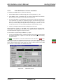
2.5.3.1. Writing a Short BAI Program ................................ 2-7
2.5.3.2. BAI Windows Software Interface ........................ 2-11
2.5.3.3. BAI MMI Windows Software Installation ........... 2-13
Parameters Screen - BAI MMI ......................................................... 2-17
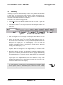
Axis Scope Tuning Window............................................................. 2-19
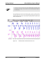
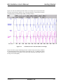
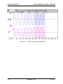
2.7.1. Tuning Procedure for Servo Loops .................................... 2-21
Autotuning........................................................................................ 2-29
Tuning Tips ...................................................................................... 2-33
COMMUNICATION AND COMMANDS .................................... 3-1
Introduction ........................................................................................ 3-1
BAI Communications Modes ............................................................. 3-1
3.2.1. Local Mode .......................................................................... 3-1
3.2.2. Remote Mode ....................................................................... 3-2
3.2.2.1. Enabling RS232 Remote Communications ............ 3-2
3.2.2.2. Daisy Chain............................................................ 3-3
Menu Commands................................................................................ 3-4
Aerotech, Inc.
iii
Table of Contents
BA Intellidrive User’s Manual
3.3.1.
3.3.2.
3.3.3.
3.4.
3.5.
iv
C-Change Parameter............................................................. 3-4
D-Display Tracking Information .......................................... 3-6
O-Other Menus..................................................................... 3-7
3.3.3.1. Running a Program ................................................ 3-7
3.3.3.2. Read Register ......................................................... 3-8
3.3.3.3. Read/Write Parameter ............................................ 3-8
3.3.3.4. Display Error Message........................................... 3-8
3.3.4. F-File Operations.................................................................. 3-9
3.3.5. F1- Abort Entry/Up One Menu Level................................... 3-9
3.3.6. F2/F3 - Previous/Next Menu ................................................ 3-9
3.3.7. F5 – Aborts Motion and Programs ..................................... 3-10
3.3.8. I – Enter Motion Command................................................ 3-10
3.3.9. S – Save Parameters to Flash.............................................. 3-10
3.3.10. T-Teach Mode.................................................................... 3-11
3.3.11. Space Bar ........................................................................... 3-12
BAI System Commands.................................................................... 3-13
3.4.1. Program/Motion Abort ....................................................... 3-14
3.4.2. Program Execution ............................................................. 3-14
3.4.3. DF Delete File .................................................................... 3-14
3.4.4. File Transfers – Download File to PC ................................ 3-14
3.4.5. Format ................................................................................ 3-15
3.4.6. Get Message Command...................................................... 3-15
3.4.7. HOLD/TRIGGER/CANCEL.............................................. 3-15
3.4.8. Execute Immediate Command............................................ 3-16
3.4.9. Print Directory.................................................................... 3-16
3.4.10. Return Error Message String .............................................. 3-16
3.4.11. Print Program “file” to Port................................................ 3-17
3.4.12. Print Status ......................................................................... 3-17
3.4.13. Return Axis Position........................................................... 3-18
3.4.14. Serial Poll command .......................................................... 3-18
3.4.15. Hardware Reset .................................................................. 3-19
3.4.16. Parameter Editing ............................................................... 3-19
3.4.17. Read/Write Register ........................................................... 3-20
3.4.18. Save Program/Parameters to Flash Memory....................... 3-20
3.4.19. Service Request Mode (SRQ) ............................................ 3-20
3.4.20. File Transfers – Upload File to BAI................................... 3-21
3.4.21. ; Comment .......................................................................... 3-22
BAI Motion and Program Commands .............................................. 3-23
3.5.1. Acceleration Command ...................................................... 3-24
3.5.2. Clear Limit ......................................................................... 3-24
3.5.3. Conditional Gosub.............................................................. 3-24
3.5.4. Conditional Goto ................................................................ 3-24
3.5.5. Disable Amplifier ............................................................... 3-25
3.5.6. Dwell Command................................................................. 3-25
3.5.7. Enable Amplifier ................................................................ 3-25
3.5.8. Fault Acknowledge............................................................. 3-25
3.5.9. Freerun ............................................................................... 3-26
3.5.10. Gain Command................................................................... 3-26
3.5.11. Gosub Command ................................................................ 3-27
3.5.12. Goto Command .................................................................. 3-27
3.5.13. Home Command................................................................. 3-27
Aerotech, Inc.
Version 1.4
BA Intellidrive User’s Manual
3.6.
3.7.
CHAPTER 4:
4.1.
4.2.
Version 1.4
Table of Contents
3.5.14. Index Command ................................................................. 3-28
3.5.15. IT Command ...................................................................... 3-29
3.5.16. Label – Define a Label ....................................................... 3-29
3.5.17. Load Position Register ....................................................... 3-29
3.5.18. Loop Start and Loop End ................................................... 3-30
3.5.19. Motor Commutate .............................................................. 3-30
3.5.20. Change opto-isolated outputs ............................................. 3-30
3.5.21. Print Message ..................................................................... 3-30
3.5.22. Position Mode – Absolute or Incremental.......................... 3-31
3.5.23. Program Stop...................................................................... 3-31
3.5.24. Ramp Time......................................................................... 3-31
3.5.25. Register Functions.............................................................. 3-32
3.5.26. Run the teach program ....................................................... 3-32
3.5.27. Return from subroutine ...................................................... 3-32
3.5.28. WM/WA – Wait Move....................................................... 3-32
Teach Mode...................................................................................... 3-33
3.6.1. Using the Teach Program................................................... 3-33
3.6.1.1. +/- Increment/Decrement Current Position ......... 3-34
3.6.1.2. F2/F3 Next/Previous Index ................................. 3-34
3.6.1.3. 1,2,3 Learn the Current
Position/Feedrate/Bit Pattern ............................... 3-34
3.6.1.4. I-Change the Index............................................... 3-35
3.6.1.5. Z-Zero the Teach Program................................... 3-35
3.6.1.6. S-Save the Teach Program................................... 3-35
Sample Programs.............................................................................. 3-36
PARAMETERS ................................................................................ 4-1
Introduction ........................................................................................ 4-1
Servo Loop Parameters....................................................................... 4-4
4.2.1. PRM:0 Proportional Velocity Gain KP............................... 4-5
4.2.2. PRM:1 Integral Velocity Gain KI ....................................... 4-5
4.2.3. PRM:2 Proportional Position Gain KPOS .......................... 4-5
4.2.4. PRM:3 Incremental Change for KP ..................................... 4-6
4.2.5. PRM:4 Incremental Change for KI ...................................... 4-6
4.2.6. PRM:5 Incremental Change for KPOS ................................ 4-7
4.2.7. PRM:6 Servo “In Position” Tolerance ................................ 4-7
4.2.8. PRM:7 Servo Peak Current Limit ....................................... 4-8
4.2.9. PRM:8 Servo RMS Limit.................................................... 4-8
4.2.10. PRM:9 Servo RMS Current Timeout .................................. 4-9
4.2.11. PRM:10 Servo Velocity Trap.............................................. 4-9
4.2.12. PRM:11 Integral Clamp .................................................... 4-10
4.2.13. PRM:12 Position Error Trap ............................................. 4-10
4.2.14. PRM:13 Servo Update Rate .............................................. 4-11
4.2.15. PRM:14 Encoder Resolution............................................. 4-11
4.2.16. PRM:15 Electrical Cycles/Mechanical Revolution ........... 4-12
4.2.17. PRM:16 Hall Effects Available......................................... 4-13
4.2.18. PRM:17 Initialization Current........................................... 4-13
4.2.19. PRM:18 Velocity Feedforward VFF ................................. 4-14
4.2.20. PRM:20 Operating Mode.................................................. 4-14
4.2.21. PRM:22 Position Save ...................................................... 4-15
4.2.22. PRM:23 Reload Saved Position on Power-Up .................. 4-15
Aerotech, Inc.
v
Table of Contents
BA Intellidrive User’s Manual
4.3.
4.4.
vi
4.2.23. PRM:24 Saved Position .................................................... 4-16
4.2.24. PRM:26 Low Pass Filter ................................................... 4-16
4.2.25. PRM:27 Phase Offset ........................................................ 4-17
4.2.26. PRM:29 Input Command Offset........................................ 4-17
4.2.27. PRM:30 Default Velocity.................................................. 4-18
4.2.28. PRM:31 Jog Value ............................................................ 4-18
4.2.29. PRM:32 In Position Bit ...................................................... 4-19
4.2.30. PRM:33 Dead Band Wait Time ........................................ 4-19
4.2.31. PRM:34 Thermistor Polarity .............................................. 4-19
4.2.32. PRM:36 Position Mode...................................................... 4-20
4.2.33. PRM:37 Estop Action ........................................................ 4-21
4.2.34. PRM:38,39 Current Offset Adjustment .............................. 4-21
4.2.35. PRM:40 Registration Input................................................. 4-21
4.2.36. PRM:41 Encoder Scale Factor ........................................... 4-22
4.2.37. PRM:42 I/O Read Time Delay ........................................... 4-22
4.2.38. PRM:43 Trajectory Type ................................................... 4-23
4.2.39. PRM:44 Encoder Fault Enable........................................... 4-23
4.2.40. PRM:45 Estop Polarity....................................................... 4-23
4.2.41. PRM:46 Send ACK after move completes ......................... 4-24
4.2.42. PRM:47 In Position Output Polarity ................................. 4-24
4.2.43. PRM:52 RMS Method ...................................................... 4-24
Limit Parameters............................................................................... 4-25
4.3.1. PRM:60 Limit Check ........................................................ 4-25
4.3.2. PRM:61 Limit Type .......................................................... 4-25
4.3.3. PRM:62 Home Direction................................................... 4-25
4.3.4. PRM:63 Home Type ......................................................... 4-26
4.3.5. PRM:64 Home Velocity.................................................... 4-26
4.3.6. PRM:65 Home Ending Offset ........................................... 4-26
4.3.7. PRM:66 Home Marker Velocity ...................................... 4-27
4.3.8. PRM:67 Negative Software Limit ..................................... 4-27
4.3.9. PRM:68 Positive Software Limit....................................... 4-27
4.3.10. PRM:69 Deceleration Distance ......................................... 4-28
4.3.11. PRM:70 +/- Limit Reset Distance ..................................... 4-28
4.3.12. PRM:71 Check Move Against Software Limits ................ 4-28
4.3.13. PRM:72 Marker Type ........................................................ 4-29
4.3.14. PRM:73 Offset to Marker................................................... 4-29
4.3.15. PRM:74 Program Execution............................................... 4-29
4.3.16. PRM:75 Home Velocity Out .............................................. 4-30
4.3.17. PRM:76 Marker Polarity.................................................... 4-30
4.3.18. PRM:77 Output Disable ..................................................... 4-30
Communications/Startup Parameters ................................................ 4-31
4.4.1. PRM:90 Baud Rate............................................................ 4-31
4.4.2. PRM:91 Service Request (SRQ) Character....................... 4-31
4.4.3. PRM:92 Displayable Digits............................................... 4-31
4.4.4. PRM:94 Unit Address ....................................................... 4-32
4.4.5. PRM:95 Enable/Disable Daisy Chain - Places in
Remote Mode ..................................................................... 4-32
4.4.6. PRM:96 Autorun Program on Power-Up .......................... 4-32
4.4.7. PRM:97 Bootup Program Name ....................................... 4-33
4.4.8. PRM:98 Status on Power-Up ............................................ 4-33
4.4.9. PRM:99 External Enable Polarity ..................................... 4-33
Aerotech, Inc.
Version 1.4
BA Intellidrive User’s Manual
4.5.
CHAPTER 5:
5.1.
CHAPTER 6:
6.1.
6.2.
6.3.
6.4.
CHAPTER 7:
7.1.
7.2.
7.3.
7.4.
7.5.
Version 1.4
Table of Contents
4.4.10. PRM:100 Display Type...................................................... 4-34
4.4.11. PRM:101 General Fault Output ......................................... 4-34
4.4.12. PRM:102 Fault Output Polarity ......................................... 4-34
Miscellaneous ................................................................................... 4-35
4.5.1. PRM:200 Position Scale Factor ........................................ 4-35
4.5.2. PRM:201 Default Ramp Time .......................................... 4-35
4.5.3. PRM:202 Filter Cutoff ...................................................... 4-35
4.5.4. PRM:204 Autotune Distance.............................................. 4-36
4.5.5. PRM:205 Autotune Velocity Loop Bandwidth .................. 4-36
4.5.6. PRM:206 Autotune Damping Factor.................................. 4-37
4.5.7. PRM:207 Start Frequency.................................................. 4-37
4.5.8. PRM:208 Autotune Sampling Time ................................... 4-37
4.5.9. PRM:209 Clock/Direction Multiplier ............................... 4-38
4.5.10. PRM:210 Acceleration...................................................... 4-38
REGISTERS ..................................................................................... 5-1
Introduction ........................................................................................ 5-1
5.1.1. RG1 Program Bytes Remaining ........................................... 5-1
5.1.2. RG2 BAI Status.................................................................... 5-1
5.1.3. RG3 Position Feedback........................................................ 5-2
5.1.4. RG4 Velocity Feedback ....................................................... 5-2
5.1.5. RG5 Position Command....................................................... 5-2
5.1.6. RG6 Position Error............................................................... 5-2
5.1.7. RG7 Current Command........................................................ 5-2
5.1.8. RG8 Firmware Version ........................................................ 5-2
5.1.9. RG9 Velocity Command ...................................................... 5-3
5.1.10. RG12 A/D Input................................................................... 5-3
5.1.11. RG14, RG15 Timers ............................................................ 5-3
MODE OF OPERATION................................................................ 6-1
Introduction ........................................................................................ 6-1
Modes of Operation............................................................................ 6-1
Indexing Mode ................................................................................... 6-1
Clock and Direction............................................................................ 6-3
TECHNICAL DETAILS.................................................................. 7-1
Introduction ........................................................................................ 7-1
BAI Control Board Jumper Selections ............................................... 7-1
The I/O Port....................................................................................... 7-2
7.3.1. Restore/Reset Signal ........................................................... 7-3
7.3.2. Clock/Direction Inputs Signals............................................. 7-3
7.3.3. Estop Input Signal ................................................................ 7-3
7.3.4. Thermistor Input Signal........................................................ 7-4
7.3.5. Analog Inputs ....................................................................... 7-4
7.3.6. Opto-Isolated Inputs............................................................. 7-4
7.3.7. Opto-Isolated Outputs .......................................................... 7-5
Encoder/Limits/Hall Effects Port P3 .................................................. 7-7
7.4.1. Encoder Interface ................................................................. 7-8
7.4.2. Limits Interface .................................................................... 7-8
7.4.3. Hall Effect Interface ............................................................. 7-9
Servo Amplifier Specifications......................................................... 7-13
Aerotech, Inc.
vii
Table of Contents
BA Intellidrive User’s Manual
7.6.
7.7.
CHAPTER 8:
8.1.
AC Input and Motor Wiring ............................................................. 7-15
7.6.1. Minimizing EMI Interference............................................. 7-15
7.6.2. Minimizing 50/60 HZ Line Interference ............................ 7-17
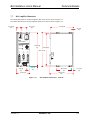
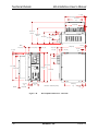
BAI Amplifier Dimensions............................................................... 7-19
7.7.1. Mounting Procedures for the BAI 10/20/30/50 .................. 7-21
7.7.2. Mounting Procedures for the BAI 75/100 .......................... 7-23
TROUBLESHOOTING ................................................................... 8-1
Amplifier Related Problems ............................................................... 8-1
APPENDIX A: GLOSSARY OF TERMS................................................................ A-1
APPENDIX B: WARRANTY AND FIELD SERVICE .......................................... B-1
INDEX
∇ ∇ ∇
viii
Aerotech, Inc.
Version 1.4
BA Intellidrive User’s Manual
List of Figures
LIST OF FIGURES
Figure 1-1.
Figure 1-2.
Figure 1-3.
Figure 1-4.
Figure 1-5.
Figure 1-6.
Figure 1-7.
Figure 1-8.
Figure 1-9.
Figure 1-10.
Figure 1-11.
Figure 1-12.
Figure 1-13.
Figure 1-14.
Figure 1-15.
BA-Intellidrive Amplifiers ................................................................. 1-1
BAI Indexer/Positioner Mode ............................................................ 1-2
Illustration of Local and Remote Mode.............................................. 1-3
Teach Mode (using DOS-based COM_BAI)...................................... 1-4
Teach Mode (using BAI MMI) .......................................................... 1-5
Teach Mode (using a Hand Held Terminal) ....................................... 1-5
Operating Mode (Clock and Direction) .............................................. 1-6
BA-Intellidrive Hardware – 10/20/30 A Models ................................ 1-7
BA-Intellidrive Hardware – 50/75/100 Models................................. 1-7
Motor and AC Power Connections – 10/20/30 Models..................... 1-8
Motor and AC Power Connections – 50/75/100 Models................... 1-9
Fuse and Inrush Limiting – 10/20/30 Models.................................. 1-10
AC Input Fusing – 50/75/100 Models .............................................. 1-11
20 – 80V Option............................................................................... 1-12
RS232 Daisy Chain .......................................................................... 1-14
Figure 2-1.
Figure 2-2.
Figure 2-3.
Figure 2-4.
Figure 2-5.
Figure 2-6.
Figure 2-7.
Figure 2-8.
Figure 2-9.
Figure 2-10.
Figure 2-11.
Figure 2-12.
Figure 2-13.
Figure 2-14.
Figure 2-15.
Figure 2-16.
Figure 2-17.
Figure 2-18.
Figure 2-19.
Figure 2-20.
Figure 2-21.
Figure 2-22.
Figure 2-23.
Figure 2-24.
Figure 2-25.
Figure 2-26.
Figure 2-27.
Figure 2-28.
Figure 2-29.
Figure 2-30.
Figure 2-31.
Figure 2-32.
Figure 2-33.
Physical Setup of the BAI and Aerotech Motors (Application 1)....... 2-3
Remote Mode Configuration .............................................................. 2-4
Local Mode Configuration ................................................................. 2-4
RS-232 Connection ............................................................................ 2-5
BAI Display Window ......................................................................... 2-6
BAI Resetting Window....................................................................... 2-6
Enter Immediate Command Screen .................................................... 2-7
DOS Editor Screen ............................................................................. 2-7
File Operations Screen ....................................................................... 2-8
File and Parameters Transfer Screen .................................................. 2-8
File Upload Screen ............................................................................. 2-9
Other Menu Options Screen ............................................................... 2-9
Auto Run/Block Run Option Screen................................................. 2-10
Enter File Screen .............................................................................. 2-10
Main Screen...................................................................................... 2-11
Programs Window ............................................................................ 2-12
Parameters Screen ............................................................................ 2-12
MMI Main Screen ............................................................................ 2-13
MMI Text Editor Window................................................................ 2-14
File Transfer Window (MMI)........................................................... 2-14
Main Screen (Run Mode) ................................................................. 2-15
Display Code (Main Screen) ............................................................ 2-16
Parameters Screen (BAI MMI)......................................................... 2-17
Motor Profiles Selection (Parameter Screen) ................................... 2-18
Axis Scope Window (BAI MMI) ..................................................... 2-19
Axis Scope Toolbars ........................................................................ 2-20
Cursors Toolbar (Axis Scope Screen) .............................................. 2-21
Flowchart of Overall Tuning Process ............................................... 2-22
Maximize Button on the Axis Scope Window.................................. 2-23
Unacceptable Velocity Error ............................................................ 2-25
Acceptable Velocity Error (When Adjusting Kp) ............................ 2-25
Unacceptable Position Error (When Adjusting Ki) .......................... 2-26
Plot Showing an Appropriate Value for Kpos .................................. 2-27
Version 1.4
Aerotech, Inc.
ix
List of Figures
BA Intellidrive User’s Manual
Figure 2-34.
Figure 2-35.
Figure 2-36.
Figure 2-37.
Figure 2-38.
Figure 2-39.
Plot Showing Overall Effects When Kpos is High ........................... 2-28
The “Gains” and “Auto Tune” Toolbars........................................... 2-29
Autotune Plot where “Dist” Has Been Set Too Low ........................ 2-30
Autotune Plot where “Dist” Has Been Set Too High........................ 2-31
Autotune Plot Showing Proper Calibration ...................................... 2-32
Tuning Plot of an AC Brushless Motor ............................................ 2-33
Figure 3-1.
Figure 3-2.
Figure 3-3.
Tracking Screen.................................................................................. 3-1
The Change Parameter Screen............................................................ 3-5
Example of Changing a Parameter in the Change Parameter
Screen ................................................................................................. 3-5
Display Tracking Screen..................................................................... 3-6
Other Menu Options ........................................................................... 3-7
Auto Run/ Block Run Option Screen.................................................. 3-7
Read Register Screen.......................................................................... 3-8
File Operation Screen ......................................................................... 3-9
Enter Immediate Command Screen .................................................. 3-10
Teach Mode (using DOS-based COM_BAI).................................... 3-11
Teach Mode (using BAI MMI)......................................................... 3-12
Teach Mode screen (COM_BAI.exe)............................................... 3-12
Parameters Affecting the Home Cycle.............................................. 3-28
Teach Mode Screen .......................................................................... 3-33
Teach Screen for Position “0” (Showing Current Position and
Teach, POS, VEL, and I/O Pattern).................................................. 3-34
Teach Screen for Position “0” (Showing Current Position and
Teach, POS, VEL, and I/O Pattern).................................................. 3-35
Figure 3-4.
Figure 3-5.
Figure 3-6.
Figure 3-7.
Figure 3-8.
Figure 3-9.
Figure 3-10.
Figure 3-11.
Figure 3-12.
Figure 3-13.
Figure 3-14.
Figure 3-15.
Figure 3-16.
Figure 4-1.
Figure 4-2.
PID Control Loop ............................................................................... 4-4
Thermistor Input Circuit ................................................................... 4-20
Figure 6-1.
Figure 6-2.
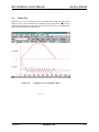
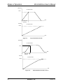
Trapezoidal Motion Profile ................................................................ 6-2
Sinusoidal Motion Profile (S-curve)................................................... 6-2
Figure 7-1.
Figure 7-2.
Figure 7-3.
Figure 7-4.
Figure 7-5.
Figure 7-6.
Figure 7-7.
Figure 7-8.
Figure 7-9.
Figure 7-10.
Figure 7-11.
Figure 7-12.
Figure 7-13.
Figure 7-14.
Figure 7-15.
Figure 7-16.
BAI Jumper Locations........................................................................ 7-2
Clock/Direction Input Circuit ............................................................. 7-3
Over Temperature Circuitry................................................................ 7-4
Electrical Characteristics of Opto-Isolated Input................................ 7-5
Electrical Characteristics of Opto-Isolated Output ............................. 7-6
CW Motor Rotation (Viewed from the Mounting Flange End) .......... 7-8
Limit Switch Input Circuit .................................................................. 7-8
Hall Effect Input Circuit ..................................................................... 7-9
Hall Effect Motor Phasing ................................................................ 7-10
Motor Rotation (From Mounting Flange End).................................. 7-10
Motor Phase Voltage Observation Scheme ...................................... 7-12
Encoder Phase Voltage Observation Scheme ................................... 7-12
Wiring to Minimize EMI and Capacitive Coupling.......................... 7-16
Wiring to Minimize EMI and Capacitive Coupling (BAI 50) .......... 7-16
Back-Propagation Line Filter Connection ........................................ 7-17
Isolation Transformer Connection (eliminates torque
disturbance) ...................................................................................... 7-18
BAI Amplifier Dimensions – 10/20/30............................................. 7-19
Figure 7-17.
x
Aerotech, Inc.
Version 1.4
BA Intellidrive User’s Manual
Figure 7-18.
Figure 7-19.
Figure 7-20.
Figure 7-21.
Figure 7-22.
Figure 7-23.
Figure 7-24.
List of Figures
BAI Amplifier Dimensions – 50/75/100........................................... 7-20
BAI Side View (10/20/30/50) .......................................................... 7-21
BAI Top View (Preferred Mounting – 10/20/30/50)........................ 7-22
Preferred Mounting of BAI Amplifiers (10/20/30/50) ..................... 7-23
Preferred Mounting - 75/100 ............................................................ 7-24
BAI Side View (75/100)................................................................. 7-25
BAI Top View (75/100) ................................................................. 7-25
∇ ∇ ∇
Version 1.4
Aerotech, Inc.
xi
List of Figures
xii
BA Intellidrive User’s Manual
Aerotech, Inc.
Version 1.4
BA Intellidrive User’s Manual
List of Tables
LIST OF TABLES
Table 1-1.
Table 1-2.
Table 1-3.
COM Port Pinouts ................................................................................. 1-13
I/O Connector Pinouts (P1) ................................................................... 1-15
Pinouts for the Encoder/Limits/Hall Effects Port (P3) .......................... 1-16
Table 2-1.
Table 2-2.
Minimum Hardware Requirements and Recommendations .................... 2-2
Initial Servo Parameter Values.............................................................. 2-23
Table 3-1.
Table 3-2.
Table 3-3.
Table 3-4.
Table 3-5.
Table 3-6.
Table 3-7.
Table 3-8.
Table 3-9.
Table 3-10.
Bit Patterns.............................................................................................. 3-6
System Commands ................................................................................ 3-13
BAI File Transfers Transmit Sequence ................................................. 3-14
Hold/Trigger/Cancel Variables ............................................................. 3-15
Bit Definitions for the PS Print Status Command ................................. 3-17
Return Axis Position Type Variables .................................................... 3-18
Return Axis Position Type Variables .................................................... 3-18
SRQ Service Request Variables ............................................................ 3-20
BAI File Transfer Receive Sequence .................................................... 3-21
Motion Commands ................................................................................ 3-23
Table 4-1.
Table 4-2.
Table 4-3.
Table 4-4.
Table 4-5.
Table 4-6.
Table 4-7.
Table 4-8.
Table 4-9.
Table 4-10.
Table 4-11.
Table 4-12.
Table 4-13.
Table 4-14.
Table 4-15.
Table 4-16.
Table 4-17.
Table 4-18.
Table 4-19.
Table 4-20.
Table 4-21.
Table 4-22.
Table 4-23.
Table 4-24.
Table 4-25.
Table 4-26.
Table 4-27.
Table 4-28.
Table 4-29.
Table 4-30.
Table 4-31.
BAI Parameters ....................................................................................... 4-1
Settings for Proportional Velocity Gain PRM:0...................................... 4-5
Settings for Integral Velocity Gain PRM:1 ............................................. 4-5
Settings for Proportional Position Gain PRM:2 ...................................... 4-5
Settings for Incremental Change for KP PRM:3 ..................................... 4-6
Settings for Incremental Change for KI PRM:4 ...................................... 4-6
Settings for Incremental Change for KPOS PRM:5 ................................ 4-7
Settings for Servo “In Position” Tolerance PRM:6................................. 4-7
Settings for Servo Peak Current Limit PRM:7 ........................................ 4-8
Settings for Servo RMS Limit PRM:8..................................................... 4-8
Settings for Servo RMS Current Timeout PRM:9................................... 4-9
Settings for Servo Velocity Trap PRM:10 .............................................. 4-9
Settings for Integral Clamp PRM:11 ..................................................... 4-10
Settings for Position Error PRM:12 ...................................................... 4-10
Settings for Servo Update Rate PRM:13............................................... 4-11
Values for Parameter PRM:14 .............................................................. 4-12
Settings for Encoder Resolution PRM:14 ............................................. 4-12
Settings for Electrical Cycles/Mechanical Revolution PRM:15............ 4-12
Settings for Hall Effects Available PRM:16 ......................................... 4-13
Settings for Initialization Current PRM:17............................................ 4-14
Settings for VFF – Velocity Feedforward PRM:18............................... 4-14
Operating Modes PRM:20 .................................................................... 4-14
Settings for Operating Mode PRM:20................................................... 4-15
Settings for Position Save PRM:22 ....................................................... 4-15
Settings for PRM:23.............................................................................. 4-15
Settings for Saved Position PRM:24 .................................................... 4-16
Settings for Low Pass Filter PRM:26 .................................................... 4-16
Settings for Phase Offset PRM:27......................................................... 4-17
Settings for Input Command Offset PRM:29 ........................................ 4-17
Settings for Default Velocity PRM:30 .................................................. 4-18
Settings for Jog Value PRM:31............................................................. 4-18
Version 1.4
Aerotech, Inc.
xiii
List of Tables
BA Intellidrive User’s Manual
Table 4-32.
Table 4-33.
Table 4-34.
Table 4-35.
Table 4-36.
Table 4-37.
Table 4-38.
Table 4-39.
Table 4-40.
Table 4-41.
Table 4-42.
Table 4-43.
Table 4-44.
Table 4-45.
Table 4-46.
Table 4-47.
Table 4-48.
Table 4-49.
Table 4-50.
Table 4-51.
Table 4-52.
Table 4-53.
Table 4-54.
Table 4-55.
Table 4-56.
Table 4-57.
Table 4-58.
Table 4-59.
Table 4-60.
Table 4-61.
Table 4-62.
Table 4-63.
Table 4-64.
Table 4-65.
Table 4-66.
Table 4-67.
Table 4-68.
Table 4-69.
Table 4-70.
Table 4-71.
Table 4-72.
Table 4-73.
Table 4-74.
Table 4-75.
Table 4-76.
Table 4-77.
Table 4-78.
Table 4-79.
Table 4-80.
Table 4-81.
Table 4-82.
xiv
Settings for In Position Bit PRM:32...................................................... 4-19
Settings for Dead Band Wait Time PRM:33 ......................................... 4-19
Settings for Thermistor Polarity PRM:34.............................................. 4-20
Settings for Position Mode PRM:36...................................................... 4-20
Settings for Estop Action PRM:37 ........................................................ 4-21
Settings for Current Offset Adjustment PRM:38, PRM:39 ................... 4-21
Settings for Registration Input PRM:40 ................................................ 4-21
Settings for Encoder Scale Factor PRM:41 ........................................... 4-22
Settings for I/O Read Time Delay PRM:42........................................... 4-22
Settings for Trajectory Type PRM:43 ................................................... 4-23
Settings for Encoder Fault Enable PRM:44........................................... 4-23
Settings for Estop Polarity PRM:45 ...................................................... 4-23
Settings for Send ACK after move completes PRM:46......................... 4-24
Settings for In Position Output Polarity PRM:47 .................................. 4-24
Settings for RMS Method PRM:52 ....................................................... 4-24
Settings for Limit Check PRM:60 ......................................................... 4-25
Settings for Limit Type PRM:61 ........................................................... 4-25
Settings for Home Direction PRM:62 ................................................... 4-25
Settings for Home Type PRM:63 .......................................................... 4-26
Settings for Home Velocity PRM:64..................................................... 4-26
Settings for Home Ending Offset PRM:65 ............................................ 4-26
Settings for Home Marker Velocity PRM:66 ........................................ 4-27
Settings for Negative Software Limit PRM:67...................................... 4-27
Settings for Positive Software Limit PRM:68 ....................................... 4-27
Settings for Deceleration Distance PRM:69.......................................... 4-28
Settings for +/- Limit Reset Distance PRM:70 ...................................... 4-28
Settings for Check Move Against Software Limits PRM:71 ................. 4-28
Settings for Marker Type PRM:72 ........................................................ 4-29
Settings for Offset to Marker PRM:73 .................................................. 4-29
Settings for Program Execution PRM:74 .............................................. 4-29
Settings for Home Velocity Out PRM:75.............................................. 4-30
Settings for Marker Polarity PRM:76.................................................... 4-30
Settings for Output Disable PRM:77..................................................... 4-30
Settings for Baud Rate PRM:90 ............................................................ 4-31
Settings for Service Request Character PRM:91 ................................... 4-31
Settings for Displayable Digits PRM:92 ............................................... 4-31
Settings for Unit Address PRM:94 ........................................................ 4-32
Settings for Enable/Disable Daisy Chain PRM:95 ................................ 4-32
Settings for Autorun Program PRM:96 ................................................. 4-32
Settings for Bootup Program Name PRM:97 ........................................ 4-33
Settings for Amplifier Status on Power-Up PRM:98............................. 4-33
Settings for External Enable Polarity PRM:99 ...................................... 4-33
Settings for Display Type PRM:100...................................................... 4-34
Settings for General Fault Output PRM:101 ......................................... 4-34
Settings for PRM:102 ............................................................................ 4-34
Settings for Position Scale Factor PRM:200 ......................................... 4-35
Settings for Default Ramp Time PRM:201 ........................................... 4-35
Settings for Filter Cutoff PRM:202 ....................................................... 4-35
Settings for Autotune Distance PRM:204 ............................................. 4-36
Settings for Autotune Velocity Loop Bandwidth PRM:205 .................. 4-36
Settings for Autotune Damping Factor PRM:206.................................. 4-37
Aerotech, Inc.
Version 1.4
BA Intellidrive User’s Manual
Table 4-83.
Table 4-84.
Table 4-85.
Table 4-86.
Settings for Start Frequency PRM:207.................................................. 4-37
Settings for Autotune Sampling Time PRM:208................................... 4-37
Settings for Clock/Direction Multiplier PRM:209 ................................ 4-38
Settings for Acceleration ....................................................................... 4-38
Table 7-1.
Table 7-2.
Table 7-3.
Table 7-4.
Table 7-5.
BAI Board Jumper Selections ................................................................. 7-1
I/O Connector Pinouts (P1) ..................................................................... 7-2
Pinouts for the Encoder/Limits/Hall Effects Port (P3) ............................ 7-7
Electrical Specifications for BAI 10/20/30 ........................................... 7-13
Electrical Specifications for BAI 50/75/100 ......................................... 7-14
Table 8-1.
Amplifier Faults, Causes, and Solutions.................................................. 8-1
List of Tables
∇ ∇ ∇
Version 1.4
Aerotech, Inc.
xv
List of Tables
xvi
BA Intellidrive User’s Manual
Aerotech, Inc.
Version 1.4
BA Intellidrive User’s Manual
Regulatory Information
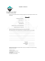
DECLARATION OF CONFORMITY
Manufacturer’s Name and Address
Aerotech, Inc.
101 Zeta Drive
Pittsburgh, PA 15238-2897
Declares that the product:
Product Name: BA Intellidrive/BA Sinedrive
Conforms to the following product specifications:
EMC: EN 55011: Class B Emissions
EN 50082-1: Immunity
EN61000-4-2
EN61000-4-3
EN61000-4-4
EN61000-4-11
EN50141
LVD:
IEC 204-1
and complies with EMC directive 89/336/EEC.
Pittsburgh, PA
October 8, 1998
David F. Kincel_________________________
Quality Assurance Manager
Robert Novotnak__________________________
Engineer Verifying Compliance
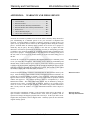
General notes concerning the test setup.
This product was tested at Compliance Labs, Middlefield, OH on October 8, 1998.
The brushless amplifier was tested with a brushless servo motor. To ensure that the
product passes the conducted emissions tests, a line filter and common mode choke must
be connected to the main inputs. The filter is a Schaffner FN 2070-10-06 and the common
mode choke is a Renco Electronics RL-1329-1200. Ferrite must be added to each line of
the main inputs but not earth ground. In order for the product to conform to the radiated
emission standards, the motor cable must be shielded and the shield must be tied to the
earth ground. Ferrite must also be added (in common mode) to the motor cable but not
around the shield. Finally, a metal 25-pin connector with a metal backshell must be used
when making a connection to the 25-pin receptacle on the amplifier. The shield of the
feedback cable must be tied to the metal backshell. Failure to follow the described
procedures may cause the amplifier/motor to exceed emission limits.
∇ ∇ ∇
Version 1.4
Aerotech, Inc.
xvii
Regulatory Information
xviii
BA Intellidrive User’s Manual
Aerotech, Inc.
Version 1.4
BA Intellidrive User’s Manual
Preface
PREFACE
This section gives you an overview of topics covered in each of the sections of this
manual as well as conventions used in this manual. This manual contains information on
the following topics:
CHAPTER 1: INTRODUCTION
This chapter contains an introduction to the hardware and software architecture of the
BA-Intellidrive.
CHAPTER 2: GETTING STARTED
Chapter 2 contains information about the components of the BAI, unpacking and
inspecting the equipment, and minimum hardware and software requirements for proper
operation. In addition, Chapter 2 walks the user through physically setting up the BAI,
connecting the signal cables, installing the software, and using the software
(COM_BAI.exe and MMI) for simple motion applications.
CHAPTER 3: COMMUNICATION AND COMMANDS
This chapter covers information regarding the communication modes, the COM_BAI
menu commands, and the programming commands.
CHAPTER 4: PARAMETERS
Chapter 4 describes the various parameters used on the BAI.
CHAPTER 5: REGISTERS
This chapter contains information about the registers on the BAI that allow the user to
read various operating parameters.
CHAPTER 6: MODE OF OPERATION
This chapter contains all information regarding the BAI’s modes of operation.
CHAPTER 7: TECHNICAL DETAILS
Contained in Chapter 7 is detailed technical information regarding the BA-Intellidrive.
CHAPTER 8: TROUBLESHOOTING
Chapter 8 provides a reference tool if problems with the BA-Intellidrive arise.
APPENDIX A: GLOSSARY OF TERMS
Appendix A contains a list of terminology and abbreviations used in this manual.
APPENDIX B: WARRANTY AND FIELD SERVICE
Appendix B contains the warranty and field service policy for Aerotech products.
Version 1.4
Aerotech, Inc.
xix
Preface
BA Intellidrive User’s Manual
INDEX
The index contains a page number reference of topics discussed in this manual. Locator
page references in the index contain the chapter number (or appendix letter) followed by
the page number of the reference.
CUSTOMER SURVEY FORM
A customer survey form is included at the end of this manual for the reader’s comments
and suggestions about this manual. Readers are encouraged to critique the manual and
offer their feedback by completing the form and either mailing or faxing it to Aerotech.
Throughout this manual the following conventions are used:
é
é
é
é
é
The terms BA-Intellidrive and BAI are used interchangeably throughout this
manual.
The text <ENTER> is used to indicate that the Enter/Return key on the keyboard
is to be pressed.
Hexadecimal numbers are listed using a preceding "0x" (for example, 0x300,
0x12F, 0x01EA, etc.,) to distinguish them from decimal numbers
Graphic icons or keywords may appear in the outer margins to provide visual
references of key features, components, operations or notes.
This manual uses the symbol "∇ ∇ ∇" to indicate the end of a chapter.
Although every effort has been made to ensure consistency, subtle differences may exist
between the illustrations in this manual and the component and/or software screens that
they represent.
∇ ∇ ∇
xx
Aerotech, Inc.
Version 1.4
BA Intellidrive User’s Manual
Introduction
CHAPTER 1: INTRODUCTION
In This Section:
• Product Overview..................................................... 1-1
• Indexer...................................................................... 1-2
• Clock and Direction.................................................. 1-6
• BAI DOS Software................................................... 1-6
• Hardware Overview and Function ............................ 1-7
• Safety Procedures and Warnings ....................... .....1-17
1.1.
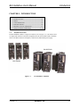
Product Overview
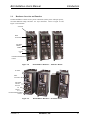
The BA-Intellidrive (BAI) is a single-axis indexer (refer to Figure 1-1). The indexer card
is coupled with Aerotech’s BA Series amplifiers and can control either brush or brushless
motors. The BAI consists of an amplifier, control board, and internal power supply.
BAI 50/75/100
BAI 10/20/30
Figure 1-1.
Version 1.4
BA-Intellidrive Amplifiers
Aerotech, Inc.
1-1
Introduction
BA Intellidrive User’s Manual
1.2.
Indexer
The BAI can act as a single-axis indexer. This means that it is capable of doing point-topoint motion by specifying a reference position, velocity, and acceleration. Some of the
other commands available are freerun (FR), home (HO), change outputs, and teach mode.
The BAI can also execute programs stored in flash memory.
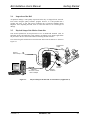
The BAI is capable of operating in two different communications modes, one is local
mode and the other is remote mode. In either mode, all commands are sent via the RS232
interface.
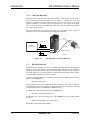
Local mode allows the user to control the BAI through a hand held terminal (HT) or a
DOS emulation program. In this mode, a menu driven interface is used to communicate
to the BAI. The menu driven interface allows the user to change parameters, run
programs, teach the unit, execute motion commands, upload and download programs
(DOS emulation only), display a tracking screen, and other functions, refer to Figure 1-2.
PMC-15
RS232
BFC-15
PC Runs COM_BAI
Or
Windows BAI MMI
•
•
PRM:20=4
the BAI is a fully programmable positioner (runs in “Local” mode)
uses a PC to setup and program
Figure 1-2.
BAI Indexer/Positioner Mode
Remote mode is intended for users who wish to embed Intellidrive commands into their
own programs or connect multiple units in a daisy chain. Interacting with the unit is done
via the remote command set. Remote mode allows the user to run programs, change
parameters, execute motion commands, print error messages, request status, and other
functions. Refer to Figure 1-3 for an illustration of remote mode and local mode.
1-2
Aerotech, Inc.
Version 1.4
BA Intellidrive User’s Manual
Introduction
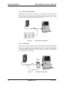
LOCAL MODE
RS232
Hand
Terminal
or
DOS emulation program
from PC (using a menu
driven interface)
REMOTE MODE
RS232
Run drive by sending commands in ASCII format.
Direct serial commands generated by a user
program. This could come from a PC or PLC (or
other serial device).
PLC
Example Commands:
‘IEN<CR>’
‘IIN5500 F10000<CR>’
‘IHO’
Figure 1-3.
Version 1.4
Illustration of Local and Remote Mode
Aerotech, Inc.
1-3
Introduction
BA Intellidrive User’s Manual
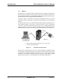
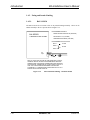
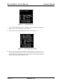
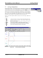
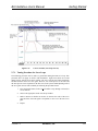
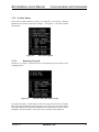
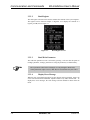
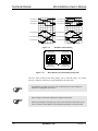
1.2.1. Teach Mode
Teach mode allows the user to teach the BAI up to 100 positions. A move from one point
to the next is accomplished by changing the opto-isolated inputs. This bit pattern is
specified by the user while teaching the unit. The user can specify either a binary 1, 0 or
X (don’t care) as the bit pattern for each of the three inputs. Each of the 100 moves has a
bit pattern associated with it. When the pattern is satisfied (see Figure 1-5), the motor
makes a move at the user specified velocity to the specified position. The present position
of the motor is displayed in the "Position" window.
The moves are sequential, meaning, they will execute in order (0, 1, 2, 3, …98, 99).
The user cannot jump out of sequential order.
Since the learned positions are absolute, running the teach program forces the unit into
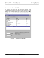
absolute position mode. The Teach mode can be executed using the "COM_BAI" DOS
emulation program (refer to Figure 1-4) or through the BAI Man Machine Interface
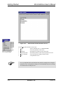
(MMI [refer to Figure 1-5]). In addition, the BAI can operate in the Teach mode using
the HT (Hand held Terminal), refer to Figure 1-6.
Figure 1-4.
1-4
Teach Mode (using DOS-based COM_BAI)
Aerotech, Inc.
Version 1.4
BA Intellidrive User’s Manual
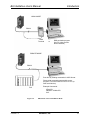
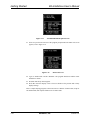
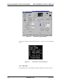
Figure 1-5.
Introduction
Teach Mode (using BAI MMI)
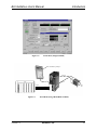
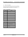
Enter Teach Mode by pressing “T”
PMC-15
PLC
BFC-15
Inputs
Figure 1-6.
Version 1.4
0
1
2
Teach Mode (using a Hand Held Terminal)
Aerotech, Inc.
1-5
Introduction
BA Intellidrive User’s Manual
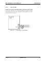
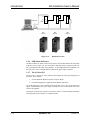
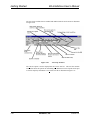
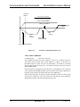
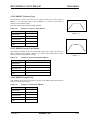
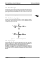
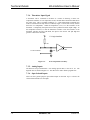
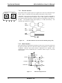
1.2.2. Clock and Direction
The BAI can also operate in clock and direction mode. In this mode, the user sends a
clock (pulse train) and direction signal, refer to Figure 1-7. During each servo loop
update (1 ms default), the BAI reads the number of new clocks and uses this as the
position command. By default, each clock represents one count from the feedback
device. However, the user can modify this so that each clock pulse represents more than
one count from the encoder.
This mode allows the user who has past experience with stepper motor systems to
upgrade to a servo system without having to change their controller.
PMC-15
Clock/Steps
INDEXER
CONTROLLER
BFC-15
(closed loop stepper)
Direction
Figure 1-7.
1.3.
PRM:20=5
Operating Mode (Clock and Direction)
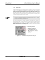
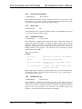
BAI DOS Software
The BAI software package is stored on a 1.44MB floppy disk, labeled “BAI Software
Package.” The software includes a HT terminal emulator (COM_BAI.exe), a program to
control the BAI in remote mode (daisy chain mode) and the source files. The purpose of
the COM_BAI.exe is to execute programs or individual commands and check the BAI’s
status information through a menu driven interface.
In order for the COM_BAI.exe to function correctly in DOS, the ansi.sys driver must be
added to the config.sys file.
DEVICE=c:\dos\ansi.sys
These programs can also run in a DOS shell under Windows 95/NT. Again, in order for
the COM_BAI.exe file to run correctly, the ansi.sys driver must be loaded. The following
examples illustrate how to load ansi.sys in Windows 95/NT.
For Windows 95, add the following line to the config.sys file.
DEVICE=c:\win95\command\ansi.sys
For Windows NT, add the following line to the config.nt file in the winnt\system32
directory.
DEVICE=%SystemRoot%\system32\ansi.sys
Restart the PC after making these changes.
1-6
Aerotech, Inc.
Version 1.4
BA Intellidrive User’s Manual
1.4.
Introduction
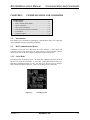
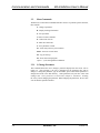
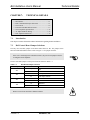
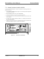
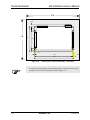
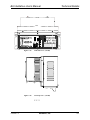
Hardware Overview and Function
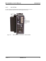
The BA-Intellidrive consists of two power connections (motor power and input power),
two LED indicator lamps, and three “D” style connectors. Refer to Figure 1-8 and
Figure 1-9 for locations.
AC Power
Motor
Connections
LED Status
Indicator
COM Port
I/O Port
P1
Encoder/Limits/Hall Effects
Port P3
Figure 1-8.
BA-Intellidrive Hardware – 10/20/30 A Models
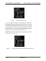
AC Power
Motor
Connections
LED Status
Indicator
Com Port
P2
I/O Port
P1
Encoder/Limits/Hall Effects
Port P3
Figure 1-9.
Version 1.4
BA-Intellidrive Hardware – 50/75/100 Models
Aerotech, Inc.
1-7
Introduction
BA Intellidrive User’s Manual
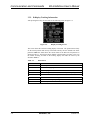
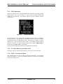
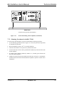
1.4.1. Motor and AC Power Connections
1.4.1.1.
BAI 10/20/30
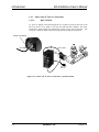
AC power is applied to the BAI through the AC receptacle located on the front of the
unit. The power cord is similar to the type used with personal computers. The motor
connection is made through the terminal strip located on the front of the BAI. This
connector contains the motor connections along with the earth ground connection.
Motor Connection
AC Power
Motor Cables
BM
Motor
110VAC or
220VAC
Figure 1-10. Motor and AC Power Connections – 10/20/30 Models
1-8
Aerotech, Inc.
Version 1.4
BA Intellidrive User’s Manual
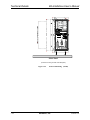
1.4.1.2.
Introduction
BAI 50/75/100
AC power is applied to the BAI through the terminal strip located on the front to the unit.
The motor and ground connections are also made through this terminal strip.
Auxiliary Power
Input
AC1
AC2
AC3
Ground
Motor Connector A
Motor Connector B
Motor Connector C
Ground
Figure 1-11.
Version 1.4
Motor and AC Power Connections – 50/75/100 Models
Aerotech, Inc.
1-9
Introduction
BA Intellidrive User’s Manual
1.4.2. Fusing and Inrush Limiting
1.4.2.1.
BAI 10/20/30
The BAI 10/20/30 do not contain a fuse or any inrush limiting internally. These can be
added externally to the AC input as shown in Figure 1-12.
RECOMMENDED MODELS:
BAI SERIES
RODAN SURGE GIARD SG100 (20A RMS)
THERMISTOR AND FUSING
KEYSTONE CL-10 (12A RMS)
AMETHERM #SL32IRO30 (30A RMS)
RECOMMENDED FUSE VALUES:
BAI10
BAI20
10 ASB
20 ASB
BAI30
A.C.
Input
G/YEL
LO BLU
BRN
HI
FUSE
DUE TO CAPACITIVE NATURE OF AMPLIFIER INPUT CIRCUIT,
CURRENT INRUSH LIMITING IS RECOMMENDED. NEGATIVE
TEMPERATURE COEFFICIENT THERMISTORS ARE USED FOR
THIS PURPOSE. THERMISTOR IS TO BE PLACED IN THE AC HI
LINE. ONLY ONE THERMISTOR NEEDED FOR ONE AMP.
ALTERNATELY, 2 THERMISTORS CAN BE USED IN AC HI & LO
FOR MULTIPLE AMPS IN PARALLEL.
Figure 1-12.
1-10
Fuse and Inrush Limiting – 10/20/30 Models
Aerotech, Inc.
Version 1.4
BA Intellidrive User’s Manual
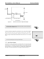
1.4.2.2.
Introduction
BAI 50/75/100
The BAI 50/75/100 contain inrush limiting internally. Fusing can be added if needed
externally (refer to Figure 1-13). The BAI 50 requires 2 phase input power while the BAI
75/100 require 3 phase input power. Earth ground should be connected to the earth
ground connection on the unit. Motor connections are made through the A, B, and C
connections on the front of the unit.
BAI SERIES
FUSING
AC3
A.C.
Input
AC2
AC1
FUSES
Figure 1-13.
Version 1.4
AC Input Fusing – 50/75/100 Models
Aerotech, Inc.
1-11
Introduction
BA Intellidrive User’s Manual
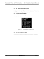
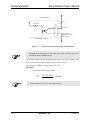
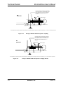
1.4.3. 20 - 80 Volt Option – BAI 10/20/30
If a BAI 10/20/30 - 80 amplifier was purchased, a separate AC input has been included on
the side of the amplifier. The internal power supply of the BA amplifier requires a
minimum of 80VAC input to operate properly. Figure 1-14 shows the connection to the
separate AC power board. The connection is made to the AC input board with a three
terminal connector (Aerotech Part # ECK00213).
G
L
H
115/240 VAC
J1
CONTROL
A.C.
115VAC
HI
1 HI (H)
OR
LO
2
LO (L)
FRAME
3
(G)
230VAC
BAI
AMPLIFIER
TB1
14VAC
BUS
A.C.
TO
56VAC
HI
5
HI
LO
6
LO
FRAME
4
(DEPENDING
ON MODEL)
Figure 1-14.
1-12
20 – 80V Option
Aerotech, Inc.
Version 1.4
BA Intellidrive User’s Manual
Introduction
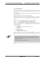
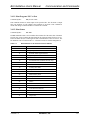
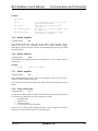
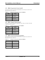
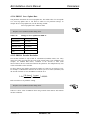
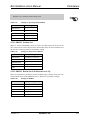
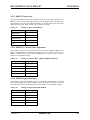
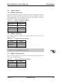
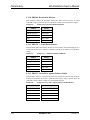
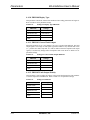
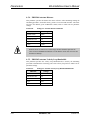
1.4.4. COM Port
The BAI is a Data Terminal Equipment (DTE) device. Consequently, the user must
connect to the COM ports with a NULL modem cable or adapter. The COM port is a
standard 9-pin “D” style connector located on the front of the BAI, refer to Figure 1-8. It
consists of two signal lines; transmit (TXD) and receive (RXD); a ground, shield, and a
5V power supply line used to power the Aerotech HT. Table 1-1 contains the connector
pinouts.
Table 1-1.
COM Port Pinouts
Pins
Function
1
Shield
2
Receive (RXD)
3
Transmit (TXD)
4,6,7,8
NC
5
Ground (GND)
9
+5 V
The 5-Volt connection on COM port is for the hand held terminal and is a nonstandard connection.
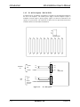
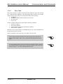
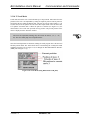
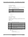
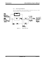
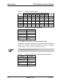
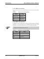
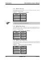
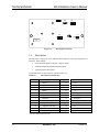
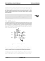
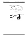
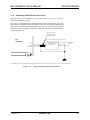
1.4.5. RS232 Daisy Chain Configuration
When connecting multiple BAIs in a RS232 daisy chain, the units must be connected so
that the transmit (TXD) of unit A connects to the receive (RXD) of unit B, and the
transmit of unit B connects to the receive of unit C. The last unit in the chain must
connect its transmit to the receive of the PC (Figure 1-15). Refer to
Chapter 3: Communication and Commands for setup of the daisy chain configuration.
Version 1.4
Aerotech, Inc.
1-13
Introduction
BA Intellidrive User’s Manual
COM Port
T
R
2
2
2
T
3
3
3
GND
5
5
5
COM
COM
COM
R
GND
BAI
(Unit A)
Figure 1-15.
BAI
(Unit B)
BAI
(Unit C)
RS232 Daisy Chain
1.4.6. LED Status Indicators
The BAI contains two LED’s located on the front of the unit that indicate the fault status
of the unit, refer to Figure 1-8. One of the LED’s indicates if power is applied to the unit,
the second indicates the status of the amplifier. A green light indicates the amplifier is in
the ready state, while a red light indicates a fault or the power stage is disabled.
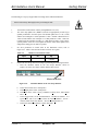
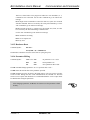
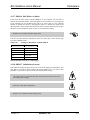
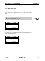
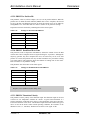
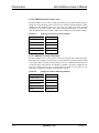
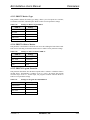
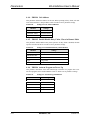
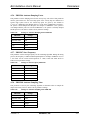
1.4.7. The I/O Port (P1)
The I/O port is a 25-pin “D” style connector that contains all of the general-purpose I/O
functions. These include:
•
six non-dedicated digital I/O signals (3 input/3 output)
•
two dedicated digital I/O signals (External Enable/Amp Fault)
All of the digital I/O is opto-isolated inputs and outputs. One of the two dedicated I/O
signals enables/disables the power stage externally and the second indicates the fault
status in the amplifier.
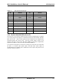
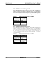
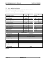
The pinouts for the 25-pin connector are shown in Table 1-2. More detailed information
about pin functions is in Chapter 7: Technical Details.
1-14
Aerotech, Inc.
Version 1.4
BA Intellidrive User’s Manual
Table 1-2.
Introduction
I/O Connector Pinouts (P1)
Pin
Function
Pin
Function
1
Shield
13
Out3
2
Input1
14
Estop
3
Input2
15, 25
Ground
4
Input3
16
+5V
5
External Enable
17
NC
6
Input Common
18
NC
7
Direction
19
Thermistor
8
Clock
20
Restore/Reset
9
Output Common
21
NC
10
Amplifier Fault Out
22
NC
11
Out1
23
NC
12
Out2
24
NC
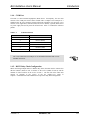
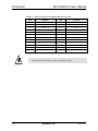
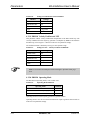
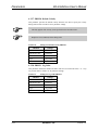
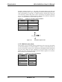
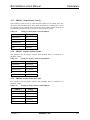
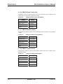
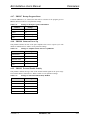
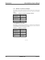
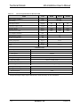
1.4.8. Encoder/Limits/Hall Effects Port (P3)
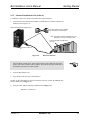
The 25-pin “D” style connector contains all of the necessary feedback inputs to complete
a servo loop. This port has inputs for a 3-channel encoder, three limit switches, and three
Hall effect devices. Each of these inputs provides feedback for the microprocessor
controlled position and velocity loops. The three encoder signals consists of the
following: sine (SIN), cosine (COS), and marker (MKR) as well as their complimentary
signals: sine-n (SIN-N), cosine-n (COS-N), and marker-n (MKR-N).
Two of the three limit inputs are end-of-travel sensing (CW Limit and CCW Limit) while
the third is a reference limit (Home Limit). The Hall effect switch inputs are
recommended for AC brushless motor commutation but not required. The pinouts for the
connector is shown in Table 1-3.
Version 1.4
Aerotech, Inc.
1-15
Introduction
BA Intellidrive User’s Manual
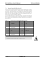
Table 1-3. Pinouts for the Encoder/Limits/Hall Effects Port (P3)
Pin
Function
Pin
Function
1
Shield
13
NC
2
NC
14
COS
3
Encoder +5
15
COS-N
4
NC
16
Limit +5
5
Hall Effect B
17
SIN
6
MKR-N
18
SIN-N
7
MKR
19
NC
8
NC
20
Limit Com.
9
NC
21
Encoder Com.
10
Hall Effect A
22
Home Limit-N
11
Hall Effect C
23, 25
NC
12
CW Limit-N
24
CCW Limit-N
The maximum encoder frequency input is 2.5 MHz per signal.
IMPORTANT
1-16
Aerotech, Inc.
Version 1.4
BA Intellidrive User’s Manual
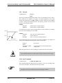
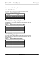
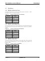
1.5.
Introduction
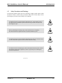
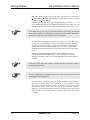
Safety Procedures and Warnings
The following statements apply wherever the Warning or Danger symbol appears within
this manual. Failure to observe these precautions could result in serious injury to those
performing the procedures and/or damage to the equipment.
To minimize the risk of electrical shock and bodily injury, ensure that the motor is
decoupled from the mechanical system and no harm to personnel will result if the
motor begins to spin.
DANGER
Before performing the following steps, ensure that the motor is completely
disconnected from the amplifier and the associated mechanical system.
DANGER
To minimize the risk of electrical shock and bodily injury when any electrical circuit
is in use, ensure that no person comes in contact with the circuitry.
DANGER
To minimize the risk of bodily injury, make certain that all electrical power switches
(all switches external to the amplifier) are in the off position prior to making any
mechanical adjustments.
DANGER
∇ ∇ ∇
Version 1.4
Aerotech, Inc.
1-17
Introduction
1-18
BA Intellidrive User’s Manual
Aerotech, Inc.
Version 1.4
BA Intellidrive User’s Manual
Getting Started
CHAPTER 2: GETTING STARTED
In This Section:
• Introduction ...................................................................2-1
• Unpacking the BA-Intellidrive .......................................2-2
• Minimum Hardware Requirements.................................2-2
• Recommended System Configurations...........................2-2
• Inspection of the BAI .....................................................2-3
• Physical Setup of the Motion Controller ........................2-3
• Local Mode ....................................................................2-4
• Standard Installation of the Software .............................2-5
• Parameters Screen - BAI MMI.....................................2-17
• Axis Scope Tuning Window.........................................2-19
• Autotuning....................................................................2-29
• Tuning Tips ..................................................................2-33
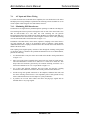
2.1.
Introduction
Chapter 2 contains information about the components of the BA-Intellidrive, unpacking
and inspecting the equipment, and minimum hardware and software requirements for
proper operation. In addition, this chapter walks the user through physically setting up the
BAI, connecting the signal cables, installing the software, using the software for simple
motion applications, and configuring the BAI for daisy chain operation.
This chapter is designed for technically oriented individuals familiar with computers
and software that want a quick setup of the BAI. This chapter is also for users that
want a simple systematic setup of the BAI. More detailed explanations about the
BAI, programming commands, and parameters are in Chapter 3 through Chapter 8.
IMPORTANT
Version 1.4
Aerotech, Inc.
2-1
Getting Started
BA Intellidrive User’s Manual
2.2.
Unpacking the BA-Intellidrive
Before unpacking any components, visually inspect the containers of the BAI for any
evidence of shipping damage. If any such damage exists, notify the shipping carrier
immediately.
All electronic equipment is wrapped in antistatic material and packaged with
desiccant (a drying agent used to reduce moisture). Make certain that the antistatic
material is not damaged during unpacking.
Remove the packing list from the BAI container. Make certain that the items listed on the
packing slip are contained within the package. The following items should be found in
every BAI package:
•
•
•
•
The indexer (BAI)
BAI User’s Manual (optional)
BAI software (on one CD)
Indexer packing slip (listing products shipped with the order)
The following list of additional items may be included with the BAI, depending on the
options and accessories that have been specified:
•
•
2.3.
Hand held terminal (HT)
BAI MMI software
Minimum Hardware Requirements and Recommended System
Configurations
Minimum hardware requirements and recommended system configurations for the BAI
are shown in Table 2-1.
Table 2-1.
2-2
Minimum Hardware Requirements and Recommendations
Equipment
Minimum
Recommended
Computer
(microprocessor)
IBM PC AT or PS/2 80486
(or higher)
or 100% compatible
80486
Computer Memory
4 MB of memory
(conventional & extended)
Graphics Display
EGA/VGA
VGA
Hard Disk Space
4 MB
5 MB or more
Mouse
Any mouse supported
by the computer
Any mouse supported
by the computer
Floppy Disk Drives
3 1/2" DSHD
CD-ROM
Windows
Windows 95/98 or NT
Windows 95/98 or NT
DOS
5.0 or higher
5.0 or higher
Aerotech, Inc.
or higher
4 MB memory
(conventional & extended)
Version 1.4
BA Intellidrive User’s Manual
2.4.
Getting Started
Inspection of the BAI
All products undergo a total quality inspection before they are shipped from Aerotech.
Even with a stringent quality assurance program, however, it is still possible that a
product will arrive in less than perfect condition due to improper handling during
shipment. After unpacking the BAI, check to ensure that there are no visible signs of
damage.
2.5.
Physical Setup of the Motion Controller
This section explains how to setup the BAI to a PC or Hand held Terminal (HT), an
applicable motor, and install the system software. In addition, some simple applications
are provided so the user can become familiar with using the BAI software.
The electrical signal connections between the BAI and Aerotech’s motors are shown in
Figure 2-1.
Programmed
Output
Motor
Cables
External
Device Output
BM
Motor
I/O
110VAC or
220VAC
COM Port
Use a NULL modem
cable or adapter
Figure 2-1.
Version 1.4
Encoder
Feedback
Physical Setup of the BAI and Aerotech Motors (Application 1)
Aerotech, Inc.
2-3
Getting Started
BA Intellidrive User’s Manual
2.5.1. BAI Cable Connections
Commands can be sent to the BAI with one of two methods: 1) Local mode and 2)
Remote mode. Local mode relies on menu screens to control the BAI, whereas remote
mode (see Figure 2-2) relies on the user sending commands through the use of an external
device acting as a host to control the BAI (e.g., PC or PLC).
RS232
PC
PLC
Figure 2-2.
Remote Mode Configuration
2.5.2. Local Mode
When the user uses the local mode, all menus and commands generation resides in the
BAI (the most common mode). The menu driven interface is done using a Handheld
Terminal or a DOS-based emulation program on a PC, refer to Figure 2-3. This program
is the COM_BAI.exe and is used to execute programs or individual commands and
checks the BAI’s status information.
Hand
Terminal
RS232
PC
Figure 2-3.
2-4
Local Mode Configuration
Aerotech, Inc.
Version 1.4
BA Intellidrive User’s Manual
Getting Started
2.5.3. Standard Installation of the Software
To install the software, the operator must follow the steps listed below.
1.
Connect the RS-232 cable between COM1 or COM2 on the PC and the COM port on
the BAI (refer to Figure 2-4).
Data Terminal Equipment (DTE) Device
Use a NULL Modem cable or adapter
when connecting to the COM ports
Note: The location of COM1 and COM2 may vary
depending on the type of PC being used.
Connects to COM1 or COM2 of the
user’s PC
Connects to COM port
P2
Data Terminal Equipment (DTE) Device
Figure 2-4.
RS-232 Connection
Since the BAI is a DTE device, the user must connect to the COM ports of the BAI
and PC with a NULL modem cable or adapter. This will ensure proper connection of
the transmit (TX) and receive (RX) signals.
2.
Insert the BAI software CD.
3.
Copy all files from the CD in to the hard drive.
In order for the COM_BAI.exe program to function correctly in DOS, the ansi.sys drive
must be added to the config.sys file.
4.
Using an editor, add the following command to the config.sys file:
DEVICE=c:\dos\ansi.sys
Version 1.4
Aerotech, Inc.
2-5
Getting Started
BA Intellidrive User’s Manual
These programs can also run in a DOS shell under Windows 95/98/NT. Again, in order
for the COM_BAI.exe program to run correctly, the ansi.sys driver must be loaded.
Using an editor, perform the following:
5.
For Windows 95/98, add the following line to the config.sys file.
DEVICE =c:\win95\command\ansi.sys
6.
For Windows NT, add the following line to the config.nt file in the winnt\system32
directory.
DEVICE =%SystemRoot%\system32\ansi.sys
7.
Restart the system PC after making these changes.
8.
Using DOS (or a DOS shell under Windows 95/98/NT), run the COM_BAI.exe from
the PC by typing "COM_BAI.exe 1 (if connected to COM 1 port). If connected to
COM 2 port, type "COM_BAI.exe 2." The screen in Figure 2-5 is the first screen
to appear.
Figure 2-5.
9.
Hit CTRL-D to reset the BAI. The display window will read "RESETTING", see
Figure 2-6.
Figure 2-6.
2-6
BAI Display Window
Aerotech, Inc.
BAI Resetting Window
Version 1.4
BA Intellidrive User’s Manual
Getting Started
10. To establish some type of motion with the system, type F4 - JOG (or index). The
motor should rotate approximately one quarter turn (or 1000 counts, this is the
default).
11. Next, enter I to display the Enter Command screen. Enter "IN 200000" to perform a
simple point-to-point move. Refer to Figure 2-7.
Figure 2-7.
2.5.3.1.
Enter Immediate Command Screen
Writing a Short BAI Program
The following steps will walk through the steps of writing a simple program, uploading
the program (file) to the BAI, and then running the program.
1.
Exit the COM_BAI and start a pure ASCII text editor such as MS-DOS Editor, type
in the program shown in Figure 2-8.
Figure 2-8.
2.
DOS Editor Screen
Save the program to the same directory containing the COM_BAI.exe file. The file
name must follow the eight-character name, three-character extension (8.3 DOS)
format. The extension must be "BAI." The filename can consist of characters or
numbers, no other symbols are allowed. So, save this program to file by calling it
"TEST1.BAI."
Version 1.4
Aerotech, Inc.
2-7
Getting Started
BA Intellidrive User’s Manual
3.
Exit the MS-DOS Editor program and restart the COM_BAI.exe.
4.
Then type F to access the File Operation screen, refer to Figure 2-9.
Figure 2-9.
5.
Type U to upload the program file just created. The screen in Figure 2-10 appears.
Figure 2-10.
6.
2-8
File Operations Screen
File and Parameters Transfer Screen
Type F and the File Upload screen appears, refer to Figure 2-11.
Aerotech, Inc.
Version 1.4
BA Intellidrive User’s Manual
Figure 2-11.
Getting Started
File Upload Screen
7.
Type in TEST1.BAI and hit return or <ENTER>. The file will upload from the PC to
the BAI. The screen should display "file transferred."
8.
Type O to access the Other Menu Options screen, refer to Figure 2-12.
Figure 2-12.
Other Menu Options Screen
20. Press 1 to run the program just uploaded to the BAI. Pressing 1 advances the user to
the following screen in Figure 2-13. This screen permits an auto run or block run of a
program. Block run steps through the program line by line, whereas, auto run
executes the program without user interaction.
Version 1.4
Aerotech, Inc.
2-9
Getting Started
BA Intellidrive User’s Manual
Figure 2-13.
Auto Run/Block Run Option Screen
21. Select 1 to perform an auto run of the program just uploaded. The Enter File screen
appears, refer to Figure 2-14.
Figure 2-14.
Enter File Screen
22. Type in "TEST1.BAI" and hit <ENTER>. The program should run and the motor
should have motion.
23. Press F1 until the top menu appears.
24. Press D to enter the Display screen. The user should see the position and velocity
displays change.
This is a simple looping program, so the motor moves a distance of 4000 counts, stops for
300 milliseconds, then repeats another move of 4000 counts.
2-10
Aerotech, Inc.
Version 1.4
BA Intellidrive User’s Manual
2.5.3.2.
Getting Started
BAI Windows Software Interface
Included in the standard software package is the BAI Windows Software Interface. This
compact windows program is intended to take the place of the COM_BAI.EXE program
for users of Windows 95/98/NT.
To install the BAI Windows Software Interface:
1.
Insert the BAI software CD into the CD-ROM drive of the PC.
2.
From Windows 95/98/NT select the start button, then click Run, and type
“X:\Install.exe” (where X is the drive letter corresponding to the CD-ROM drive).
If the BAI MMI was purchased, this may start the MMI installation and not the
software interface. Since the BAI MMI contains advanced features not available in
the standard software package, it is the preferred interface.
The BAI Software Interface program is designed to have all its features right at your
fingertips. A view of the Software Interface screen can be seen in Figure 2-15.
Figure 2-15.
Main Screen
Editing Programs in the BAI Software Interface is done similar to COM_BAI. Use any
text editor (such as Notepad) to create your program and save the file with a .BAI
extension.
Uploading/Downloading and Running programs is taken care of in the Programs window.
Figure 2-16 shows the Programs window.
Version 1.4
Aerotech, Inc.
2-11
Getting Started
BA Intellidrive User’s Manual
Figure 2-16.
Programs Window
Editing Parameters on the BAI is as easy as the click of a button. The parameters screen
brings up a listing of common parameters, as well as allowing the user to change any
parameter documented in this manual. Figure 2-17 shows the BAI Software Interface
Parameters Screen.
Figure 2-17.
2-12
Aerotech, Inc.
Parameters Screen
Version 1.4
BA Intellidrive User’s Manual
2.5.3.3.
Getting Started
BAI MMI Windows Software Installation
To install the BAI MMI software, perform the following.
1.
Insert the BAI software CD into the floppy drive of the system PC (e.g., X:\).
2.
From Windows 95/98 (or Windows NT 4.0) select the Start button, then click the
Run icon, type in X:\install.exe in the Open box and Click OK.
3.
A new pop-up window will be displayed. Enter the name of the target sub-directory
of the installation. By default, the Install.EXE program will install the BAI software
under the C:\ProgramFiles\BA IntellidriveMMI sub-directory. If a different sub
directory is desired, change the target directory from this pop-up window. If a new
sub-directory does not exist, the installation program will automatically create it.
4.
Follow any subsequent instructions that are displayed on the screen.
When installation is complete, a “BAI MMI” entry is placed under the Programs menu,
which appears after pushing the Start button. This indicates that the installation was
successful and that the program is ready to be started.
To write and run a program using the MMI is very simple.
1.
To start the BAI MMI software, push the Start button, then select Programs and find
the program group "Bai". Figure 2-18 is the main screen that appears after starting
the MMI software.
The
button indicates a successful communication link to the BAI. A
button
indicates that no link was established with the BAI. Press the red link button to attempt
establishing communication again. If the button stays red, check the RS232 cable and
ensure a NULL modem cable is being used. Also, check to make sure the correct COM
port on the PC is selected under the communication menu.
Figure 2-18.
Version 1.4
MMI Main Screen
Aerotech, Inc.
2-13
Getting Started
BA Intellidrive User’s Manual
2.
To write a program using the MMI, select File and Programs… from the pull-down
menu. This will start the text editor, refer to Figure 2-19.
Figure 2-19.
3.
As with the COM_BAI.exe, type in the same program code in the text editor. Save
this one as "TEST2.BAI" using the Save As… function from the File pull-down
menu on the text editor.
4.
Open the transfer window (Figure 2-20) by selecting File, then Transfer from the File
pull-down menu.
Figure 2-20.
2-14
MMI Text Editor Window
File Transfer Window (MMI)
Aerotech, Inc.
Version 1.4
BA Intellidrive User’s Manual
Getting Started
5.
Select (or highlight) the file just created from the PC directory, then select the " ["
key to transfer the file to the BAI directory.
6.
Select File, then Run from the File pull-down menu.
Notice that the Previous Error Message box in the lower right changes to a smaller box
with five buttons to the left of it, refer to Figure 2-21.
Figure 2-21.
7.
Main Screen (Run Mode)
Select the "Program List" button, the program(s) transferred to the BAI should be
displayed in the box to the right of the button.
Notice that the "Program List" button changes; it now reads Display Code. Also, notice
that the Step, Cycle, and Stop buttons are half-toned.
8.
Highlight the "test2.bai" program in the box, then select the "Display Code" button.
The lines of code for test2.bai are displayed in the box, refer to Figure 2-22.
Version 1.4
Aerotech, Inc.
2-15
Getting Started
BA Intellidrive User’s Manual
Figure 2-22.
Display Code (Main Screen)
The previous two buttons that were displayed in half tone are now selectable.
9.
To run the program, select the Cycle button.
Notice that the program cycles through the lines of code in the box as it cycles through
the moves.
2-16
Aerotech, Inc.
Version 1.4
BA Intellidrive User’s Manual
2.6.
Getting Started
Parameters Screen - BAI MMI
The Parameters screen contains four tabs labeled Motion Parameters, Limits,
Communications, and Miscellaneous. From these four groups of parameters, the user can
change the value of a specific parameter, refer to Figure 2-23. Also, there is a Motor
Profiles pull-down menu that permits the user to select a motor profile and type if using
Aerotech’s motors or a generic motor profile if using non-Aerotech motors, refer to
Figure 2-24.
Figure 2-23.
Version 1.4
Parameters Screen (BAI MMI)
Aerotech, Inc.
2-17
Getting Started
BA Intellidrive User’s Manual
Figure 2-24.
Motor Profiles Selection (Parameter Screen)
From the File pull-down menu, the user can:
•
•
•
•
•
•
Open
Save
Download
Download & Exit
Reset to Defaults
Exit
- opens a parameter file (i.e., PARAMS.PRM)
- saves new parameter values on PC
- downloads new parameter values to the BAI
- downloads parameter values and exits parameter screen
- resets all parameter settings to default values
- exits parameter screen
It is very important that user download all new parameter settings before exiting the
parameter screen. If the parameter settings are not downloaded, the previous settings
are used and all new settings are lost.
2-18
Aerotech, Inc.
Version 1.4
BA Intellidrive User’s Manual
2.7.
Getting Started
Axis Scope Tuning Window
The Axis Scope window is a tool that aids the user in improving the performance of the
control-system servo loop. The Axis Scope window is accessed by the Tuning selection
from the main menu across the top of BAI MMI main screen. When tuning an axis, Axis
Scope is used to move the axis in a forward direction and then in a reverse direction. As
the axis moves, servo data such as Position Error, Velocity Error, Velocity Command,
etc., is collected. The Axis Scope window allows the user to analyze these signals and
adjust the servo gains appropriately, thus improving an axis to its realistic optimal
performance. Refer to Figure 2-25 for an illustration of the Axis Scope screen.
There are seven menu options available to the user on the Axis Scope window, the
options are:
½ File
½ Plot
½ Trigger
½
½
½
½
Collect
Display
Units
Tools
- permits the operator to specify plot options and which signals to plot
- permits the operator to specify a data collection method, motion
options, and control options
- used to specify the number of data points to be collected in a single set
- used to specify the number of data points displayed or plotted
- specifies distance and time measurement units for the plot display
- used to enable and disable the display of four toolbars
Figure 2-25.
Version 1.4
Axis Scope Window (BAI MMI)
Aerotech, Inc.
2-19
Getting Started
BA Intellidrive User’s Manual
The Axis Scope toolbars that are enabled and disabled with the Tools menu are illustrated
in Figure 2-26.
Figure 2-26.
Axis Scope Toolbars
The Cursors option is used to display/hide the Cursors tool bar. This tool bar contains
features that assist the operator in determining time differences between points on the plot
as well as frequency information. The Cursors tool bar is illustrated in Figure 2-27.
2-20
Aerotech, Inc.
Version 1.4
BA Intellidrive User’s Manual
Figure 2-27.
Getting Started
Cursors Toolbar (Axis Scope Screen)
2.7.1. Tuning Procedure for Servo Loops
The following procedure can be used as a guide when tuning the BAI servo loop. This
procedure does not apply to motors with tachometers. Figure 2-28 shows the overall
tuning process with the Axis Scope window. The user’s system may behave differently
and have different values for servo gains. However, the overall process is the same and
the same process can be repeated for the other axes in the system. When adjusting each of
the servo gains, the user will essentially be following the procedure below:
1.
Press the Single button on the Control toolbar to step through a forward or
reverse motion.
2.
Observe the signal plots on the Axis Scope window.
3.
Make a decision on whether to increase or decrease the value of the servo
gain and if the observed signal is acceptable to move on to the next servo
gain.
4.
Repeat.
Version 1.4
Aerotech, Inc.
2-21
Getting Started
BA Intellidrive User’s Manual
START
1
Turn off Position Error & Integral Error
2
Set Servo Loop Update Rate
3
Set Servo Gains to Initial Values
4a
4
Adjust Kp Gain
Adjust Velocity Loop
4b
Adjust Ki Gain
5
Adjust Position Loop
(Adjust Kpos Gain)
6
Turn on Position Error & Integral Error
FINISHED!
Figure 2-28.
2-22
Flowchart of Overall Tuning Process
Aerotech, Inc.
Version 1.4
BA Intellidrive User’s Manual
Getting Started
The following is a step-by-step procedure for tuning motors without tachometers.
Please read each step thoroughly before performing the task.
1.
Turn off the “Position Error” fault by setting PRM:12 to 0 (zero).
2.
The “Servo loop update rate” (PRM:13) must be set appropriately in order to get
optimal performance from the system. The default update rate is 1 ms (1 kHz)
and the user would put a 4 as that parameter’s value. Another common choice is
.25ms (4 kHz) and the user would put a 1 as that parameter’s value. Some low
resolution systems (500 line encoders, etc.), high inertia systems, or low velocity
systems perform better at a lower update rate such as 1 kHz. If the update rate is
changed, the tuning process must be repeated.
3.
Set servo parameters to initial value in the Parameters screen, refer to
Figure 2-23. Table 2-2 has the initial values for these servo gains.
Table 2-2.
4.
IMPORTANT
Initial Servo Parameter Values
Kpos
Ki
Kp
0
0
≤100000
Prepare the Axis Scope Screen for tuning by performing the following functions:
a. Press the maximize button on the Axis Scope Window, shown in
Figure 2-29 so the Axis Scope window fills the entire screen.
Maximize Button
Figure 2-29.
b.
c.
d.
e.
f.
Maximize Button on the Axis Scope Window
In the Collect menu select “2500 points.”
In the Display menu select “2500 points.”
In the Plot menu, select Velocity Command, Velocity Error, and Position
Error.
In the Trigger menu, set the Forward Motion... and Reverse Motion... to a
typical move such as IN 50000 F50000 for Forward Motion... and IN 50000 F50000 for Reverse Motion... Also set the Sample Rate to 1.
In the Tools menu select Status, Control, and Gains.
Version 1.4
Aerotech, Inc.
2-23
Getting Started
BA Intellidrive User’s Manual
When the “Single” button is pressed, the motor will first move as specified by
Forward Motion... When the Single button is pressed again, the motor will move
as specified by Reverse Motion...
5.
Adjust the Velocity Loop using “Kp”. The Kpos and Ki have been set to zero
(0) to eliminate the Position Loop and half of the Velocity Loop. Thus, the only
gain that is having an effect is Kp, which is the other half of the Velocity Loop.
Even though the user may only be concerned with how well the stage positions, the
Velocity Loop cannot be overlooked as it is interrelated to positioning. The better a
stage tracks velocity, the closer it will be to its correct position.
The objective in adjusting Kp, is to reduce the velocity error to 5-10 units. The
velocity must not be eliminated completely because Ki will do that. Also, the
user wants the axis to feel “snug”. As Kp is increased, observe that the motor
shaft (or ball screw) becomes increasingly snug. The user can turn the shaft
manually and it won’t move back to its original position, but it becomes harder
to turn.
In between pressing the Single button, the operator should observe no
screeching and howling from the motor . Noise means Kp is set too high
causing it to oscillate. It may screech a little during the move, but not when at a
standstill.
If the motor doesn’t move, Kp is too low. Increase the value of Kp and try again by
pressing the Single button.
If you are adjusting the gains that Aerotech has setup for your system, use the
existing Kp as your starting point.
Once the motor is moving back and forth, the user should see a graph similar to
Figure 2-30. From this graph, it is seen that there are 20 to 30 units of velocity
error. “Kp” must be increased to reduce the amount of velocity error. After
repeating this process a few times, the velocity error will look similar to
Figure 2-31. From this graph the user can observe that the average velocity error
during the move is about 6 units. Moreover the motor does not oscillate when it
is stopped.
2-24
Aerotech, Inc.
Version 1.4
BA Intellidrive User’s Manual
Figure 2-30.
Figure 2-31.
Version 1.4
Getting Started
Unacceptable Velocity Error
Acceptable Velocity Error (When Adjusting Kp)
Aerotech, Inc.
2-25
Getting Started
BA Intellidrive User’s Manual
The user can stop adjusting “Kp” and start adjusting “Ki”.
Use a starting value of 1000 for Ki. The main objective in adjusting Ki is to
reduce velocity error and position error. As Ki is increased, the error is reduced.
However, the position error should not cross its “zero line”, otherwise it will
increase the settling time of the axis. This is a point where the user can stop
adjusting Ki. Also, a very large Ki will introduce low frequency oscillation in
the position error. From the perspective of the stage, this is vibration. Lack of
smoothness may or may not be acceptable to the user. Shown in Figure 2-32, is
a plot showing Ki crossing its “zero line” and some oscillation.
Figure 2-32.
Unacceptable Position Error (When Adjusting Ki)
Depending on the application, the user may or may not be too concerned with vibration in
the axis. However, the crossover of the position error means the Velocity Loop is too
tight, especially if maintaining position is important to the user. Due to this cross-over,
the settling time increases and the Kpos (which is in the Position Loop) must work harder
to keep the motor in position. The two gains start working against each other instead of
complimenting each other.
Shown in Figure 2-33 is a graph with a much better Ki. As can be observed from the
position error, it is smoother and the position error does not cross over the horizontal axis.
Moreover, the velocity error has been reduced as well.
2-26
Aerotech, Inc.
Version 1.4
BA Intellidrive User’s Manual
Getting Started
The user can stop adjusting “Ki” and start adjusting “Kpos.”
6.
Adjust the Position Loop using “Kpos.” Use a starting value of 500-1000 for
Kpos. As the user increases Kpos, it will be observed that the position error is
reduced The main objective is to adjust Kpos until the position error is within
user’s tolerance or starts to oscillate; whatever comes first.
As previously mentioned, if Kpos is too high, the user will encounter a high
frequency oscillation (stage vibrates strongly). This will cause the BAI to have a
RMS Current Trap, which essentially means that too much current is being sent
to the motor (the RMS Current Trap acts the same way as a fuse).
Shown in Figure 2-33 is a plot of a good Kpos. From this graph it can be seen
that there is little settling time. In other words, the position error ends near
the same time the Velocity Command ends; so the move is “in position” at the
end of the commanded move. For comparison, Figure 2-34 illustrates a plot
where Kpos is too high.
Figure 2-33.
Version 1.4
Plot Showing an Appropriate Value for Kpos
Aerotech, Inc.
2-27
Getting Started
BA Intellidrive User’s Manual
Figure 2-34.
7.
Plot Showing Overall Effects When Kpos is High
Turn the Position Error and Integral Error Traps on by returning to the
Parameters window and selecting the Parameter tab called “Faults.” Turn the
“Position Error” and the “Integral Error” back on by checking the boxes. This
will reactivate these traps.
Save and exit the Parameters window.
Reinitialize the BAI.
2-28
Aerotech, Inc.
Version 1.4
BA Intellidrive User’s Manual
2.8.
Getting Started
Autotuning
Autotuning is a procedure that automatically identifies motor parameters and determines
the motor gains. The process involves giving a sinusoidal velocity command to an axis.
From the voltage and current used by the motor, motor parameters are identified and the
motor gains are determined from the motor parameters.
To autotune an axis, use the following procedure:
1.
2.
From the Tools menu of the Windows software, select the Axis Tuning... option. The
Axis Scope screen will appear.
From the Tools menu of the Axis Scope screen, select the Gains option and the Auto
Tune option. The Gains and Auto Tune toolbars will be displayed on the screen. See
Figure 2-35.
Figure 2-35.
3.
4.
5
6
7.
The “Gains” and “Auto Tune” Toolbars
Make sure the gains are not set too high. Lower the Kpos value if the axis goes into
oscillations or the axis traps during the autotuning procedure.
On the Auto tune panel, there are two text boxes that affect the motion of the axis.
One of these boxes is the frequency or “Freq” box. Autotuning will excite the axis
with a sinusoidal command of three different frequencies. The first frequency is
displayed in the frequency box. The second frequency is twice that of the first
frequency, and the third frequency is twice that of the second frequency. When first
starting, set the first frequency to 1 Hz.
The “Dist” text box is the number of machine steps the axis will go for the first
frequency. When first starting, set this value to approximately two revolutions of the
motor shaft.
When these values are set, hit the Tune button and the sinusoidal commands will be
given to the axis. Following the completion of the motion, a pop up window showing
the gains determined by the autotuning procedure should be displayed. Selecting OK
will write the gains to the parameter file.
If an error occurs, examine the torque output. The output should be a sinusoid. If the
torque appears to be clipped near 10V, lower either the number of steps or the
frequency and retry the procedure. If the torque is low with a peak of less than a volt,
increase the number of steps or the frequency.
The torque should be examined even if gains were determined. Autotuning should
be run again to achieve a better tuned system, if the torque is not generally
sinusoidal with a peak value greater than one volt.
Version 1.4
Aerotech, Inc.
2-29
Getting Started
BA Intellidrive User’s Manual
The other text boxes on the Auto Tune panel, bandwidth (BW) and damping, affect
the calculation of the gains. These values refer to the desired frequency response of
the velocity loop.
Three autotuning plots are shown in the following Figures. Figure 2-36 shows results of
an autotune where “Dist” was set too low. The torque output is generally less than a volt
and the commanded velocity plot is not sinusoidal. This stage should be retuned with the
number of steps increased.
Figure 2-36.
2-30
Autotune Plot where “Dist” Has Been Set Too Low
Aerotech, Inc.
Version 1.4
BA Intellidrive User’s Manual
Getting Started
Figure 2-37 shows an autotune plot where there are too many steps. The plot shows that
the torque output becomes clipped at 10V. This stage should be re-tuned with the number
of steps decreased, so that the torque output is no longer clipped.
Figure 2-37.
Autotune Plot where “Dist” Has Been Set Too High
Figure 2-38 shows a proper autotuning procedure. Both the torque and velocity command
are sinusoidal and the torque output peak is greater than one volt. A resulting plot similar
to this should identify the parameters of the motor/stage and produce gains that will allow
the stage to be run adequately.
Version 1.4
Aerotech, Inc.
2-31
Getting Started
BA Intellidrive User’s Manual
Figure 2-38.
2-32
Autotune Plot Showing Proper Calibration
Aerotech, Inc.
Version 1.4
BA Intellidrive User’s Manual
2.9.
Getting Started
Tuning Tips
Shown in Figure 2-39 is a tuning plot of an AC brushless motor. Notice the ripple effect
during the move. This is normal since AC brushless motors usually have a larger torque
ripple than DC brush motors. This ripple effect has been observed to be 10 machine steps
peak with an unloaded AC brushless motor.
Figure 2-39.
Tuning Plot of an AC Brushless Motor
∇ ∇ ∇
Version 1.4
Aerotech, Inc.
2-33
Getting Started
2-34
BA Intellidrive User’s Manual
Aerotech, Inc.
Version 1.4
BA Intellidrive User’s Manual
CHAPTER 3:
Communication and Commands
COMMUNICATION AND COMMANDS
In This Section:
• Introduction ...................................................................3-1
• BAI Communications Modes .........................................3-1
• Menu Commands............................................................3-4
• BAI System Commands ...............................................3-13
• BAI Motion and Program Commands ..........................3-23
• Teach Mode..................................................................3-33
• Sample Programs..........................................................3-36
3.1.
Introduction
This chapter covers information regarding the communication modes, the COM_BAI
menu commands, and the programming commands.
3.2.
BAI Communications Modes
Commands can be sent to the BAI with one of two methods: 1) Local mode and
2) Remote mode. Local mode relies on menu screens to control the BAI, whereas
remote mode relies on the user sending commands through the RS-232 port.
3.2.1. Local Mode
The default mode for the BAI is local. All menus and command generation resides in
the BAI. The menu driven interface is done using a Hand held Terminal (HT) or a
DOS-based emulation program on a PC. The first screen the user will see using the
DOS emulation program is shown in . This is the tracking screen (COM_BAI).
Figure 3-1.
Version 1.4
Tracking Screen
Aerotech, Inc.
3-1
Communication and Commands
BA Intellidrive User’s Manual
3.2.2. Remote Mode
The BAI can be completely controlled remotely. Remote commands are sent in ASCII
format to the BAI followed by an End-Of-String (EOS) character (the line feed)
<LF>[0x0A].
Some commands cause the BAI to return data. This data is in ASCII format terminated
by the EOS character.
The RS232 interface does not use hardware handshake signals.
The BAI can also be put into service request mode (SRQ). SRQ mode sends a character
to the host when an event occurred. The host should then poll the BAI to determine its
status.
In RS232 remote mode, the SRQ is generated with a programmable character.
3.2.2.1.
Enabling RS232 Remote Communications
Remote mode operation is enabled by setting PRM:95=1 and specifying the address of
the unit. The default address is “A”. The following sequence can be used to put the
unit into remote mode.
1. Set PRM:95=1.
2. Set PRM:94=address (enter the numerical ASCII value).
3. Save parameters
4. Issue a reset.
5. Send 0x03 (CTRL-C).
6. Send 0x02 (CTRL-B).
7. Send the address defined by PRM:94.
Steps 1 and 2 only need to be done once, meaning, once PRM:95 is set to 1 and the
address is defined, the unit will bootup in remote mode until PRM:95 is changed back
to 0.
If part of this procedure fails and the user cannot regain control of the unit in
remote mode, sending a CTRL-A (0x1) will put the unit back into local mode (if
the baud rate is correct).
CTRL-A is a toggle between local and remote.
The DOS terminal program, TERM_BAI.exe, can be used to operate the BAI in remote
mode.
3-2
Aerotech, Inc.
Version 1.4
BA Intellidrive User’s Manual
3.2.2.2.
Communication and Commands
Daisy Chain
Daisy chain operation is similar to single unit remote operation except each unit must
have a different address (PRM:94). The following procedure should be used to enable
multiple units in a daisy chain. For each unit in the chain, do the following:
• Set PRM:95=1
• Set PRM:94=address (must be different for each unit)
• Save parameters
• Issue a reset
In order to address a BAI, the user must send the following commands:
• Send 0x03 (CTRL-C)
• Send 0x02 (CTRL-B)
• Send the address of the target unit defined in PRM:94
• Send a remote command
Each time a unit is opened, the above commands must be sent. These commands close
the open unit and open a new unit.
If these commands are sent incorrectly, a reset will be sent to all units.
If part of this procedure fails and the user cannot regain control of the unit in
remote mode, sending a CTRL-A (0x1) will put all of the units back into local
mode.
Any non-printable character sent to the BAI will be sent back to the PC. Since the
non-printable characters (0x00 to 0x1F) are global commands, (all the units in the
chain [see Figure 1-15]) will be transmitted back to the PC.
Version 1.4
Aerotech, Inc.
3-3
Communication and Commands
3.3.
BA Intellidrive User’s Manual
Menu Commands
The BAI uses certain menu commands that allow the user to perform specific functions,
these include:
C - Change a parameter.
D - Display tracking information.
F – File operations.
I - Enter a motion command.
O – Other menu screens.
T - Enter the teach mode.
S – Save parameter to flash.
F1 – Abort entry/return to previous menu.
F2/F3 – Previous or Next menu.
F4 – Jog (at start up).
F5 – abort motion and program.
<space> - cycles through menu commands.
3.3.1. C-Change Parameter
This command allows the user to change a parameter displayed on the screen, refer to
Figure 3-2. After pressing C, the user is prompted for the parameter they want to
change. To change the parameter, type in the number, press return and the parameter is
changed and saved to the flash memory. Some parameters may not take effect until
issuing a reset. These parameters are discussed in Chapter 4: Parameters. Pressing
the F1 key aborts changing the parameter. When changing the parameters, the user also
sees the absolute parameter number.
3-4
Aerotech, Inc.
Version 1.4
BA Intellidrive User’s Manual
Figure 3-2.
Communication and Commands
The Change Parameter Screen
The servo loop gains (i.e., KP, KI, and KPOS) can be changed in two different ways.
They can be changed by entering in a number directly, or they can be
incremented/decremented by pressing I (increment) or D (decrement). The amount
they are changed is determined by three other parameters. They are KP_INC, KI_INC,
and KPOS_INC. For convenience, these parameters are shown on the screen following
the servo loop gain screen. The user can see this screen by pressing the ‘F3’ key (if the
current screen shows the servo loop gains). This capability allows the user to
dynamically change the servo loop gains. When using the increment/decrement mode,
the gains are not saved to flash memory until pressing the enter key.
All parameters have upper and lower bounds. These bounds are provided in
Chapter 4: Parameters. If the user enters a number for a parameter that is out of the
allowable range, an error message appears.
Figure 3-3.
Version 1.4
Example of Changing a Parameter in the Change Parameter Screen
Aerotech, Inc.
3-5
Communication and Commands
BA Intellidrive User’s Manual
3.3.2. D-Display Tracking Information
After pressing the D key, the user will see the following screen in Figure 3-4.
Figure 3-4.
Display Tracking Screen
This screen shows the real time tracking display of the BAI. The position and velocity
are the current position and velocity of the BAI scaled by the user defined scale factor
parameter PRM:200. Status shows the current status of the BAI. The bit patterns are
shown in Table 3-1. The last line shows whether or not the BAI is in a limit or if it is on
the marker. Pressing F4 while in the tracking display will index the motor by the
amount in PRM:31.
Table 3-1.
Bit Patterns
Bit #
3-6
Function
bit 0:
1 = position error within limits set in PRM:6
bit 1:
1 = running program
bit 2:
1 = program execution error / immediate command error
bit 3:
1 = illegal remote command (cleared by serial poll ‘Q’)
bit 4:
1 = axis fault (cleared by FAULT ACK)
bit 5:
1 = command is executing
bit 6:
1 = service request pending
bit 7:
1 = any error
Aerotech, Inc.
Version 1.4
BA Intellidrive User’s Manual
Communication and Commands
3.3.3. O-Other Menus
These other available options are used to run programs, read registers, read/write
parameters and examine system error messages. View Figure 3-5 for other available
menu options.
Figure 3-5.
3.3.3.1.
Other Menu Options
Running a Program
Pressing “1” in Figure 3-5 advances the user to the following screen in Figure 3-6 for
running programs.
Figure 3-6.
Auto Run/ Block Run Option Screen
The options in Figure 3-6 allow the user to auto run a program or block run a program.
Block run mode steps through a program line by line, whereas, auto run mode executes
the program without user interaction. Regardless of the option chosen, the user will be
prompted to enter the filename. If any errors occur, a message will be displayed.
Version 1.4
Aerotech, Inc.
3-7
Communication and Commands
3.3.3.2.
BA Intellidrive User’s Manual
Read Register
The read register selection can be used to examine the contents of the system registers.
The registers can be found in Chapter 5: Registers. To re-display the contents of a
register, press R, refer to Figure 3-7.
Figure 3-7.
3.3.3.3.
Read Register Screen
Read/Write Parameter
The read/write parameter screen is selected by pressing 3. The user has the option of
reading a parameter, writing a parameter or saving the parameter(s) to flash memory.
After a parameter value has been changed, it is only changed in RAM. Also,
certain parameters require a reset (CTRL-D) to be issued before they take effect.
3.3.3.4.
Display Error Message
When an error occurs during operation, an error message will be generated. Errors can
occur from invalid motion commands, amplifier faults or any other external fault. To
display these error messages, the error message selection should be chosen from the
menu.
3-8
Aerotech, Inc.
Version 1.4
BA Intellidrive User’s Manual
Communication and Commands
3.3.4. F-File Operations
This screen allows the user to upload/download files, parameters, and teach programs
from the BAI to a PC, refer to Figure 3-8. Also, the user can delete programs and
examine the file directory. This function requires the DOS emulation software
COM_BAI.exe.
Figure 3-8.
File Operation Screen
After pressing the ‘F’ key, the user will be prompted to upload a file (U), download a
file (D) or quit (F1). For uploading or downloading, the user must enter a filename.
All filenames follow the eight-character name, three-character extension (8.3 DOS)
format for files. The file extension must be “BAI”. The filename itself can consist of
characters or numbers. No other symbols are allowed. For example, “PROG1.BAI” is
allowed, whereas “PRG_1.TST” is not allowed.
The BAI and the COM_BAI.exe software accomplish all error checking.
3.3.5. F1- Abort Entry/Up One Menu Level
Pressing F1 aborts the current menu operation or moves up one level in the menu.
3.3.6. F2/F3 - Previous/Next Menu
This command allows the user to change the displayed parameters. The parameter
screens are circular, (i.e., if the user continually presses F3 or F2, they will eventually
return to the starting screen).
Version 1.4
Aerotech, Inc.
3-9
Communication and Commands
BA Intellidrive User’s Manual
3.3.7. F5 – Aborts Motion and Programs
Pressing F5 while motion is taking place will abort motion (decelerate the motor to zero
(0).If programs are running, the programs will stop along with motion. The user must
issue a FA (Fault Acknowledge) or reset after pressing F5.
3.3.8. I – Enter Motion Command
This mode allows the user to execute single motion commands from the command line,
refer to Figure 3-9. Any valid motion command can be entered. See Section 2.7 for
motion commands.
Figure 3-9.
Enter Immediate Command Screen
3.3.9. S – Save Parameters to Flash
This command saves all parameters, programs, and teach programs to flash memory.
3-10
Aerotech, Inc.
Version 1.4
BA Intellidrive User’s Manual
Communication and Commands
3.3.10. T-Teach Mode
Teach mode allows the user to teach the BAI up to 100 positions. Movement from one
position to the next is accomplished by setting the input bit pattern. This bit pattern is
specified by the user while teaching the unit. The user can specify either a binary 1, 0 or
X (don’t care) as the bit pattern for each of the three inputs. Each of the 100 moves has
a bit pattern associated with it. When the pattern is satisfied (see Figure 3-11), the
motor makes a move at the user specified velocity position. The present position of the
motor is displayed in the "Position" window.
The moves are sequential, meaning, they will execute in order (0, 1, 2, 3, …98,
99). The user cannot jump out of sequential order.
Since the learned positions are absolute, running the teach program forces the unit into
absolute position mode. The Teach mode can be executed using the "COM_BAI" DOS
emulation program (refer to Figure 3-10) or through the BAI Man Machine Interface
(MMI [refer to Figure 3-11]).
Figure 3-10. Teach Mode (using DOS-based COM_BAI)
Version 1.4
Aerotech, Inc.
3-11
Communication and Commands
Figure 3-11.
BA Intellidrive User’s Manual
Teach Mode (using BAI MMI)
Teach mode is discussed in more detail in Section 3.5. Figure 3-12 is the Teach mode
screen.
Figure 3-12.
Teach Mode screen (COM_BAI.exe)
3.3.11. Space Bar
Pressing the space bar cycles through the available commands on the top-level menu.
3-12
Aerotech, Inc.
Version 1.4
BA Intellidrive User’s Manual
3.4.
Communication and Commands
BAI System Commands
This section covers the system commands used by the BAI. These commands are
typically used when using the BAI in remote mode. The host (PC/controller) can issue a
system command via RS232 for various functions. The system commands are not used
in BAI program. Commands used in BAI program are covered in Section 3.5.
Table 3-2.
System Commands
Command
Function
AB
Abort program and or motion
AR
Autorun a program
BR
Block run a program
DF
Delete file
DL
Download file
FM
Format Data
GM
Get Message
HD
Enable/Disable hold mode
I
Execute immediate command
PD
Print Directory
PE
Display error message
PP
Print program
PS
Print Status
PX
Return axis position
Q
Serial poll
RE
Reset unit
RP
Read parameter
RR
Read Register
SP
Save parameters to flash
SR
Define service request character
TR
Trigger
UL
Upload file
WR
Write Register
WP
Write Parameter
Version 1.4
Aerotech, Inc.
3-13
Communication and Commands
BA Intellidrive User’s Manual
3.4.1. Program/Motion Abort
Command Syntax:
AB <LF>
0x15 – Aborts motion to all axes in a daisy chain
This command causes a currently executing program to abort. All axes will stop and
hold position and the program will unload itself.
3.4.2. Program Execution
Command Syntax:
AR prog.BAI <LF>
Auto run a program.
BR prog.BAI <LF>
Block run a program.
Load program "prog" into memory. The program name can consist of numbers (0-9)
and letters (A-Z, a-z). The extension must be “.BAI”.
In AUTO run mode, the program begins execution immediately. A SRQ will be sent if
there is a syntax error in the program. A SRQ can be sent if a run-time error occurs,
otherwise the SRQ will be sent when the program completes. If in the HOLD mode, the
BAI will not initiate execution of the program until receiving the "TR" command.
In BLOCK run mode, the program will not begin execution immediately. An SRQ will
be sent if there is a syntax error. The program can be executed block by block by
sending TR commands. The BAI generates SRQ's after each block.
3.4.3. DF Delete File
Command Syntax:
DF filename <LF>
This command deletes the filename from the BAI directory.
3.4.4. File Transfers – Download File to PC
Command Syntax:
Table 3-3.
DL Filename<LF> Send file from BAI to HOST (PC).
(Download )
BAI File Transfers Transmit Sequence
Direction of Transfer
Command
1) HOST > BAI
"DLfilename<LF>"
2) HOST < BAI
"numbytes<LF>"
3) HOST > BAI
ACK/NAK
4) HOST < BAI
file data
5) HOST < BAI
"checksum<LF>"
The host sends a download file command and the file name (followed by < LF >) to the
BAI. The "filename" is the file to transfer.
The BAI responds with the number of bytes that it is going to transmit. This is an
ASCII string terminated by the < LF> character.
The host should then send the ACK (0x6) character when it is ready to accept the data.
If the host does not want to download this data, it should send the NAK (0x18)
3-14
Aerotech, Inc.
Version 1.4
BA Intellidrive User’s Manual
Communication and Commands
character. If the file does not exist, the BAI returns a file size of "0" bytes. The host
should send a NAK to abort transmission.
The BAI transmits the file data to the host.
The BAI transmits the checksum as an ASCII string terminated by the < LF> character.
The checksum is calculated by accumulating each byte of the file data to a 16 unsigned
integer.
3.4.5. Format
Command Syntax:
FM 0 <LF>
FM 1 <LF>
This format command allows the user to control how numbers are returned from the
BAI. IF the argument is 0, the returned data is an ASCII Dec. If the argument is 1, the
data is returned as ASCII Hex.
3.4.6. Get Message Command
Command Syntax:
GM <LF>
The GM command can be used to retrieve messages from the BAI under the following
conditions:
1) a PM (motion level command) command is used in a program, and
2) the BAI is a daisy chain mode and the unit is not selected.
When the BAI is running in daisy chain mode and a particular unit tries to write a string
to the serial port, the BAI verifies that it is the currently selected unit. If it is, it will
send the string out of the serial port. If it is not, it will write the string to a buffer where
it can be extracted at a later time with the GM command.
3.4.7. HOLD/TRIGGER/CANCEL
Command Syntax:
Table 3-4.
HD x <LF>
TR <LF>
Hold/Trigger/Cancel Variables
x
Service Request Mode
1
Enable hold mode
0
Cancel hold mode
When in the hold mode, programs will load, but not execute until issuing the TR
command. If the Global trigger command is sent, all units in the chain will leave HOLD
mode and begin execution. Refer to Table 3-4 for variable settings.
The trigger command (TR) is also used to advance a program when running in
blockmode.
Version 1.4
Aerotech, Inc.
3-15
Communication and Commands
BA Intellidrive User’s Manual
3.4.8. Execute Immediate Command
Command Syntax:
Icmdstring <LF>
This command can be used to send motion commands to the BAI, primarily when
sending ASCII strings to the BAI in remote mode (see Section 3.5 for the motion
commands). A syntax error or execution error will be indicated by bit #2 of the status
byte. A service request will be sent if enabled. The "PE" command can be given to
retrieve an error message. Bit #5 of the status byte indicates that the command is
executing. When the command is finished, a service request will be sent if enabled.
Example:
IEN
IHO
IIN 10000 F50000
IFA
etc.
3.4.9. Print Directory
Command Syntax:
PD <LF>
Prints a list of all files currently in the BAI’s flash memory.
Example:
To BAI
From BAI
PD<LF>
TEST1.BAI
PROG1.BAI
3.4.10. Return Error Message String
Command Syntax: PE < LF >
This command returns the last error message in the system. Error messages will be
generated under the following conditions:
• When a syntax error occurs with an immediate command or a statement in a
program
• When a runtime error occurs while executing a program, such as an axis limit
• When an invalid remote command is sent.
The error message is cleared when a successful command is sent. The BAI will return
the message followed by a <LF>.
Example:
"Error: Axis in limit"
3-16
Aerotech, Inc.
Version 1.4
BA Intellidrive User’s Manual
Communication and Commands
3.4.11. Print Program “file” to Port
Command Syntax:
PP filename <LF>
This command returns an ASCII output of the specified file. The file name is output
first. Line numbers are also added at the beginning of each line. This command is
useful when using a terminal emulator to check a file’s content.
3.4.12. Print Status
Command Syntax:
PS <LF>
The PS command returns a 32-bit number that contains all of the status bits of the BAI.
The first byte (8 bits) contains the data found in the serial poll status (Section 3.4.14.).
These bits allow the user to interrogate the unit to determine the source of an error. The
bit definitions can be found in Table 3-5. This data can also be found reading REG:2.
Table 3-5.
Bit Definitions for the PS Print Status Command
Bit Number
If Bit = 1
0-7
Status
8-10
Opto Input Status
11
12-14
Version 1.4
External enable signal asserted
Opto output status
15
Fault out active
16
Invalid Hall state (brushless motors only)
17
RMS fault
18
Position error fault
19
Velocity error fault
20
Amplifier fault
21
Encoder fault
22
Flash memory fault
23
Estop fault
24
Thermistor fault
25
Hall A
26
Hall B
27
Hall C
28
CCW limit encountered
29
CW limit encountered
30
Home Marker active
31
Amp active
Aerotech, Inc.
3-17
Communication and Commands
BA Intellidrive User’s Manual
3.4.13. Return Axis Position
Command Syntax:
PXn < LF>
All positions are scaled to user units. "n" is the position type. If "n" is omitted, the BAI
will feedback case 8, the encoder position.
Table 3-6.
Return Axis Position Type Variables
n
Feedback type
4
Scaled by PRM:200
8
Encoder position in counts
0
Encoder position in counts (default)
Example:
PX4<CR>
10247850.123
PX8<CR>
250075680
3.4.14. Serial Poll command
Command Syntax:
Q < LF >
This is the serial poll status byte initiated by a "Q” command in RS232 mode. The BAI
is requesting service if bit #6 is set. Reading the serial poll byte clears this bit. The data
is returned in ASCII hex.
Example:
Q <LF>
Table 3-7.
Return Axis Position Type Variables
Bit
If Bit = 1
bit 0:
1 = position error within limits set in PRM:6
bit 1:
1 = running program
bit 2:
1 = program execution error / immediate command error "i..."
bit 3:
1 = illegal remote command ( cleared by serial poll 'Q' )
bit 4:
1 = axis fault ( cleared by fault acknowledge )
bit 5:
1 = command is executing
bit 6:
1 = service request pending
bit 7:
1 = any error
bit 0: 1 = If set, the position error is within the limits set in PRM:6
bit 1: 1 = program is currently running
bit 2: set when:
1) Program runtime error.
2) Immediate command syntax error ("I...").
3-18
Aerotech, Inc.
Version 1.4
BA Intellidrive User’s Manual
Communication and Commands
This bit is cleared when a new program is loaded or a new immediate ("I...")
command is sent to the BAI. Use the "PE" command to get an ASCII error
message.
bit 3: illegal remote command was sent to the BAI or a syntax error occurred
with that command. This bit is cleared by the serial poll command ’Q’. Use the
"PE" command to get an ASCII error message.
bit 4: axis fault occurred, i.e. position error, rms current error, limit, etc. This
bit is cleared by the fault acknowledge command "IFA".
Use the "PE" command to get an ASCII error message.
bit 5: command is executing
bit 6: service request sent
bit 7: any error
3.4.15. Hardware Reset
Command Syntax:
RE <LF>
0x4 (CTRL - D) – Global Reset
The BAI does a hardware reset, this is the same as cycling the power.
3.4.16. Parameter Editing
Command Syntax:
WPn value <LF>
:set parameter "n" as "value"
RPn
<LF>
:return parameter "n"
SP
<LF>
:saves parameter data to disk
The WP command changes parameter "n" to a specified value "value”.
The RP returns the ASCII value of the parameter specified.
The SP command saves the file back to the flash memory. The save process can take
several seconds. During this time serial communications are blocked out. The BAI
sends a service request when finished. It is recommended that the service request mode
be enabled when saving the parameters.
After changing a parameter, an SP must be issued to save the parameter to flash
memory.
Version 1.4
Aerotech, Inc.
3-19
Communication and Commands
BA Intellidrive User’s Manual
Example:
To BAI
WP5 1000<LF> (write 1000 to parameter 5)
RP14<LF>
From BAI
To BAI
4000<LF>
SP<LF>
(read parameter 14, encoder
resolution)
(save parameters)
3.4.17. Read/Write Register
Command Syntax:
RRn < LF>
WRn <LF>
Where x is a register number to read.
BAI registers contain remote configuration and status information. Each register is a
32-bit number that can be read using the RR command. The BAI registers can be found
in Chapter 4. All registers can be written to, however, Registers 0-29 are for system
use and their contents are not guaranteed.
Example:
To BAI
From BAI
RR2 <LF>
123456 <LF>
To BAI
WR 32 10000 <LF>
3.4.18. Save Program/Parameters to Flash Memory
Command Syntax:
SP <LF>
Must be sent after issuing WP commands, to save the parameters to flash memory.
3.4.19. Service Request Mode (SRQ)
Command Syntax:
Table 3-8.
SRx < LF >
SRQ Service Request Variables
x
Service Request Mode
1
Turn on SRQ
0
Turn off SRQ
c
Set service request character to “c”
This command turns the service request mode (SRQ) on or off. Also used to set the
SRQ character for RS232 mode "c", refer to Table 3-8. The BAI generates a service
request (SRQ) under the following conditions:
•
•
•
•
•
3-20
Program is finished executing in AUTO mode
Block has finished executing in BLOCK mode
Immediate command has finished execution
Runtime error in the program
Syntax error in the program
Aerotech, Inc.
Version 1.4
BA Intellidrive User’s Manual
•
•
Communication and Commands
An axis error such as a limit or position error occurs
An illegal remote command is sent
The normal response to a service request ( SRQ ) is to serial poll the BAI ("Q"). The
user can then determine the source of the error from the status byte.
3.4.20. File Transfers – Upload File to BAI
Command Syntax:
(upload)
Table 3-9.
UL filename<LF> Send file from HOST (PC) to BAI
BAI File Transfer Receive Sequence
Direction of Transfer
Command
1)HOST-->BAI
"ULfilename<LF>"
2)HOST-->BAI
"numbytes<LF>"
3)HOST<--BAI
ACK/NAK
4)HOST-->BAI
file data
5)HOST<--BAI
"checksum<LF>"
The host sends an upload file command and file name (followed by an end of string
character < LF > to the BAI. The "filename" is the file to transfer.
The host sends the number of bytes to upload to the BAI. This is an ASCII string
terminated by < LF >.
The BAI responds with one character. If it is ready to accept the data, the BAI sends the
ACK (0x6) character. If there is a problem, the BAI sends the NAK (0x18) character
and file transfer aborts.
This step may take several seconds since the BAI is preparing to write to flash
memory.
Host sends file data to the BAI.
The BAI returns an ASCII string with the 16-bit checksum.
The checksum is calculated by accumulating each byte of the file data to a 16-bit
unsigned integer. The BAI returns either a checksum of 0 or 1 if a file write error
occurred.
The maximum file size = 5KB with out comments. The total number of lines in a page
is 500. 1 byte = 1 char.
Version 1.4
Aerotech, Inc.
3-21
Communication and Commands
BA Intellidrive User’s Manual
3.4.21. ; Comment
Comments can be added to the program with the semicolon “;”. During file transfer to
the BAI, everything after the “;” is ignored and not stored in the flash memory. This
was done to conserve memory.
EXAMPLE:
HO
RA 0.1
IN 1000 F2000
3-22
;home axis
;0.1 second ramp
;move 1000 units @2500 feedrate
Aerotech, Inc.
Version 1.4
BA Intellidrive User’s Manual
3.5.
Communication and Commands
BAI Motion and Program Commands
This section covers the programming commands used by the BAI. The programming
commands alphabetically listed in Table 3-10 can be used in a program or remote mode
by adding the letter "I" to the front of the command.
Table 3-10.
Motion Commands
Command
Function
AC
Set Acceleration
CL
Clear Limit
CS
Conditional gosub
CT
Conditional goto
DI
Disable amplifier
DW
Dwell for x milliseconds
EN
Enable amplifier
FA
Fault Acknowledge
FR
Freerun
GA
Set loop gains
GS
Goto subroutine
GT
Goto label
HO
Home an axis
IN
Point-to-point move
IT
Wait for input to change
LB
Program label
LE/LS
Loop ending Loop starting
LD
Load position register
MC
Motor commutate
OT
Change output
PM
Print message
PR AB
Absolute mode
PR IN
Incremental mode
PS
Program stop
RA
Set the ramp time
RG
Register function
RT
Run teach program
SR
Return from subroutine
WM
Wait Move
WA
Wait for move to finish
Version 1.4
Aerotech, Inc.
3-23
Communication and Commands
BA Intellidrive User’s Manual
3.5.1. Acceleration Command
Command Syntax:
AC acceleration
This command can be used to set the acceleration of the motor in user units/s2. If the
acceleration is set to a non-zero value, acceleration will be used instead of the ramp
time. Note that using the AC command also changes PRM:210.
3.5.2. Clear Limit
Command Syntax:
CL
This command will clear a limit from within a program. Note that PRM:74 must be set
to a 1 for this work from within a program.
3.5.3. Conditional Gosub
Command Syntax:
CS label ARG1
This command is a conditional gosub based on the ARG1. ARG1 can be either a bit
pattern of the opto-isolated inputs or a conditional compare based on register contents.
When this statement is reached in a program, the BAI will branch to label if the
condition is true, otherwise it will continue with the next statement. The label must be
defined elsewhere in the program. The subroutine must be defined after the PS
statement and contain an SR.
Where bitpattern is I2I1I0
Example:
CS 20 X01
:
LB 20
;wait here for input1=0 and input0=1
CS 33 RG33<20000
;if RG33 is less than 20000, gosub
;to label 33
CS
;if RG53 is not equal to RG45, then
;beginning of subroutine
44 RG53~RG45
;gosub to label 44
When using compare statements, the register must always be on the left-hand side of
the compare statement. The valid compare statements are <(less), >(greater than), =
(equal to), and ~ (not equal to).
3.5.4. Conditional Goto
Command Syntax:
CT label ARG1
This command is a conditional goto based on the ARG1. ARG1 can be either a bit
pattern (where bitpattern is I2I1I0) of the opto-isolated inputs or a conditional compare
based on register contents. When this statement is reached in a program, the BAI will
branch to label if the condition is true, otherwise it will continue with the next
statement. The label must be defined elsewhere in the program.
3-24
Aerotech, Inc.
Version 1.4
BA Intellidrive User’s Manual
Communication and Commands
Example:
CT 30 101
:
LB 30
CT 20 X01
CT 33 RG33<20000
CT 44 RG53~RG45
;CT 30 branches to LB 30 line and
;continues execution
;wait here for input1=0 and
;input0=1
;if RG33 is less than 20000, goto
;to table 33
;if RG53 is not equal to RG45,
;then goto to label 44
3.5.5. Disable Amplifier
Command Syntax:
DI
This command disables the power stage on the amplifier. When the power stage is
disabled, the servo loop continually updates the position feedback register,
consequently, it does not forget its location. After disabling the power stage, the enable
LED will turn red.
3.5.6. Dwell Command
Command Syntax:
DW x
This command stops program execution for x milliseconds. “x” is the amount of time to
dwell in msec.
Example:
DW 150
;Dwell for 150ms
3.5.7. Enable Amplifier
Command Syntax:
EN
This command enables the power stage on the amplifier. When the power stage is
enabled, the enable LED will turn green.
If a fault has not been acknowledged (with a FA command), the amplifier will not
enable.
3.5.8. Fault Acknowledge
Command Syntax:
FA
If a fault occurs during operation, it must be cleared before any motions commands can
be executed or any programs can be run. Faults can occur from:
• an amplifier fault
• position errors
• velocity overspeed
• over travel limit switch encountered.
If the axis is in a limit, the FA command attempts to clear the limit by moving the
motor in the reverse direction to back off of the limit switch.
Version 1.4
Aerotech, Inc.
3-25
Communication and Commands
BA Intellidrive User’s Manual
3.5.9. Freerun
Command Syntax:
FR ARG 1
FR 0
The freerun command commands the motor to move at the feedrate given by ARG 1,
where ARG1 can be a number or a register. The motor continues to move at this
feedrate until a fault occurs, the FR 0 command is issued or another freerun command
is issued. During acceleration/deceleration, the trajectory generator uses the current
ramp time to accelerate the motor.
Example:
FR 30000
FR RG66
;freerun motor to 30,000 counts/sec.
;freerun motor to contents of RG66
It is possible to do simple velocity profiling with the freerun command. For example,
the velocity can be changed by us of an input.
50000
Example:
FR 20000
IT 101
FR 50000
20000
Input Changes
;start a free run of 20,000 counts/sec
;wait for input 101
;move to a velocity of 50,000 counts/sec
The commands between the freeruns can be non-motion commands. For example, the
velocity can be changed when the position reaches a certain value:
FR RG77
LB 20
CT 20 RG3<100000
FR 20000
;start freerun
;wait until position exceeds 100,000 counts
;change speed
When using the freerun for velocity profiling, the speeds must be the same polarity.
This command should be used with caution on motors connected to linear stages.
IMPORTANT
3.5.10. Gain Command
Command Syntax:
GA KPx KIx KPOSx Vffx
This command changes the PID gains for the controller. The user can change either
one or more of the gains. The gains can be listed in any order.
The gains are not saved to flash memory after issuing this command.
3-26
Aerotech, Inc.
Version 1.4
BA Intellidrive User’s Manual
Communication and Commands
3.5.11. Gosub Command
Command Syntax:
GS label
This command calls a subroutine from within a program. The label must be defined
elsewhere in the program. All subroutines must also have an SR statement.
[Subroutines must appear after the PS (program stop command)].
EXAMPLE:
IN 2000 F2000
DW 100
GS 20
PS
LB 20
FR 20000
SR
3.5.12. Goto Command
Command Syntax:
GT label
This command forces a branch in program execution. The label must be defined
elsewhere in the program.
EXAMPLE:
GT 10
:
:
LB 10
IN 2000 F2000
3.5.13. Home Command
Command Syntax:
HO
The home cycle is used to move the motor to a hardware-referenced position.
Figure 3-13 hows where each parameter affects the home cycle.
1.
2.
3.
4.
5.
6.
The axis moves towards the home limit switch in the direction specified by
PRM:62 at a feedrate provided by PRM:64.
When the BAI encounters the home limit switch (PRM:63 and PRM:61), it
decelerates the motor to 0 speed.
The motor reverses direction at a speed provided by PRM:75.
Once the motor leaves the home limit, it moves a distance provided by
PRM:73 at velocity provided by PRM:64.
The BAI searches for the marker pulse (PRM:72) at feedrate given by
PRM:64.
After the marker is found, the motor moves an extra distance provided by
PRM:65.
Version 1.4
Aerotech, Inc.
3-27
Communication and Commands
Home Limit
PRM:63
BA Intellidrive User’s Manual
Home Direction PRM:62
Home in Velocity PRM:64
Marker Type PRM:72
Position Register
Reset to 0
Home Ending
Offset
PRM:65
Offset to
Marker
PRM:73
Marker Search
Velocity PRM:66
Home Out Velocity PRM:75
Figure 3-13.
Parameters Affecting the Home Cycle
3.5.14. Index Command
Command Syntax:
IN distance F feedrate
This command will move the motor a distance of distance at a feedrate of feedrate.
The distance and/or feedrate can be either numbers or registers. If the BAI is in
incremental mode, the motor will move the full distance. If the BAI is in absolute
mode, the motor will move the distance. Incremental or absolute mode can be selected
with the PR command.
The acceleration is determined from the ramp time or from PRM:212. The ramp time
can be specified with the RA command or the acceleration from the AC command. If a
ramp time is not specified, the default ramp time is used (PRM:201).
Before motion takes place, the trajectory generator determines if the move can be made
with the given parameters. If the move cannot be made with the given parameters,
adjustments are made to ensure that the final position is met.
3-28
Aerotech, Inc.
Version 1.4
BA Intellidrive User’s Manual
Communication and Commands
EXAMPLE:
IN 25000 F10000
IN RG55 F RG45
3.5.15. IT Command
Command Syntax:
IT I2I1I0
Wait for input to change to state I2I1I0. This command, when used in a program, halts
execution of the program until the inputs match the state given by “I2I1I0”, where
I=0,1,X (don’t care). For example, assume the following program is executing.
EXAMPLE:
IN 10000 F10000
IT X01
IN –100000
;Wait for Bit2 = don’t care, Bit1
= ;0, Bit0 =1
;index at last feedrate
After executing the first command, the BAI waits until the input is 01. Since the first
digit is a don’t care (X), only two of the three inputs must match to continue program
execution.
3.5.16. Label – Define a Label
Command Syntax:
LB label
This command defines labels in programs for branching. Branches are required for
goto (GT), gosub (GS). Conditional goto (CT) and conditional gosub (CS); only
numbers can be used as labels.
EXAMPLE:
GT 10
:
:
LB 10
IN 2000 F2000
3.5.17. Load Position Register
Command Syntax:
LD x
This command allows the user to load the position feedback with a register with an
arbitrary value (x).
Version 1.4
Aerotech, Inc.
3-29
Communication and Commands
BA Intellidrive User’s Manual
3.5.18. Loop Start and Loop End
Command SyntaxLE
;loop end
LS
;loop start
The LS/LE command set allow a sequence of moves to execute x number of times.
Where x equals 1 to 500.
Loops cannot be nested.
The example makes five incremental moves.
EXAMPLE:
:
:
LS 5
IN 10000 F25000
LE
:
:
3.5.19. Motor Commutate
Command Syntax:
MC volts
MC 0
This command outputs a voltage given by volts to the amplifier. When issued, this
command disables the PID loop. Issuing a value of zero disables the amplifier and
resets the servo loop.
3.5.20. Change opto-isolated outputs
Command Syntax:
OT O2O1O0
Change the opto-isolated output to O2O1O0 , where O=0,1,X (no change made).
EXAMPLE:
OT X01
;set OUTPUT0=1, OUTPUT1=0,
;OUTPUT2=Don’t Care
3.5.21. Print Message
Command Syntax:
PM “String
PM RGxx
This command can be used to print messages to the RS232 port from a program. If
trying to print a string, a beginning quote “ must be used. The contents of registers can
also be printed.
PM “Hello World <LF>
PM RG38 <LF>
3-30
Aerotech, Inc.
Version 1.4
BA Intellidrive User’s Manual
Communication and Commands
3.5.22. Position Mode – Absolute or Incremental
Command Syntax:
PR AB (Absolute)
PR IN (Incremental)
This mode defines how the BAI interprets a move. If set to absolute mode, the BAI
interprets indexing commands as the final position. For example, the command IN
100000 F100000 will move the motor to position 100000 regardless of where the motor
is currently sitting. If the mode is incremental, this same command will move the motor
100000 user units.
3.5.23. Program Stop
Command Syntax:
PS
This command signifies the end of the program and must be used before subroutines.
Ex:
GS 20
PS
LB 20
…
SR
3.5.24. Ramp Time
Command Syntax:
RA time
This command sets the ramp time for trajectory generator. The Ramp Time is used
during acceleration and deceleration. The unit for the ramp time is seconds. Note that
if the acceleration command AC is used or PRM:210 ≠ 0, the ramp time will be
ignored.
EXAMPLE:
RA .015
Version 1.4
;set ramp time to 15 milliseconds
Aerotech, Inc.
3-31
Communication and Commands
BA Intellidrive User’s Manual
3.5.25. Register Functions
The BAI supports a number of register (integer) based operations. These include
assignment, compare, and integer math. Registers are named by combining RG with a
specific number. The system registers are RG0-RG29 and the general purpose registers
are RG30-RG70. The system registers should not be used to store results as they will
be overwritten by the system, unless the registers are being reset.
Assignment: Registers are loaded with a value or the contents of another register.
RG30 = RG33
RG30 = -30000
Integer Math: The BAI supports +, -, /, and * for mathematical operations.
RGxx = ARG1 + ARG2
RGxx = ARG1 - ARG2
RGxx = ARG1 * ARG2
RGxx = ARG1 / ARG2 – integer result only, fractions are lost
Where ARG1, ARG2 can be either integers or other registers. Note the system
registers, RG0-RG29, should only appear on the right hand side of the equals sign.
3.5.26. Run the teach program
Command Syntax:
RT
This command runs the learned teach program (see Section 2.7.).
3.5.27. Return from subroutine
Command Syntax:
SR
This command specifies the end of a subroutine and causes program flow to return back
to the calling program.
3.5.28. WM/WA – Wait Move
Command Syntax:
WM ARG 1 F ARG2 – start move
WA – wait for move to complete
The WM command is similar to the IN command in that it can be used to define a
point-to-point move, however, unlike the IN command, which stops program execution
until the move is complete, execution will continue. Between the WA and WM
commands, the user can change outputs, change registers, wait for inputs and other nonmotion commands. The WA will halt program execution until the move completes.
EXAMPLE:
WA 50000 F RG33
OT 110
IT 001
WA
3-32
;start a move
;change outputs
;wait for input
;wait for move to complete
Aerotech, Inc.
Version 1.4
BA Intellidrive User’s Manual
3.6.
Communication and Commands
Teach Mode
Teach mode allows the user to specify up to 100 learned positions. Each learned point
consists of a position , a feedrate and a bit pattern. A move from one position to the
next is initiated by toggling the I/O lines. Up to three I/O lines can be specified for the
move to occur. Each move is equivalent to the following lines of a program:
IT I1I2I3
IN distance F feedrate
This means, move distance user units at a feedrate of user units/sec. For example, IT
101 IN 20000 F5000. Wait until the inputs are 101 and then move the motor 20000
user units.
The teach mode can only be run in local mode, (i.e., the user must use either a
Handheld ASCII terminal or the DOS program COM_BAI.exe). Teach mode is
entered by pressing T.
3.6.1. Using the Teach Program
After entering teach mode on the BAI, the user will see the following screen in
Figure 3-14. A teach program “ends” when both position and feedrate are zero. The
user can upload and download teach programs to and from the PC.
When teaching programs, the unit will default to incremental mode, however, all
the positions are interpreted as absolute positions when the program is run.
Figure 3-14.
Teach Mode Screen
The first line of this screen shows the motors current position (scaled by PRM:200).
The second, third and fourth lines show the position, velocity and I/O pattern for the
current index. In this case, the index is zero. The bottom right part of the screen shows
the various options available to the user. The following sections describe these options.
Version 1.4
Aerotech, Inc.
3-33
Communication and Commands
3.6.1.1.
BA Intellidrive User’s Manual
+/- Increment/Decrement Current Position
Hitting the +/- key on the keypad moves the motor by the amount defined in PRM:31 at
a feedrate defined by PRM:30.
3.6.1.2.
F2/F3 Next/Previous Index
Pressing the F2 or F3 key increments or decrements through the learned positions.
3.6.1.3.
1,2,3 Learn the Current Position/Feedrate/Bit Pattern
This command teaches the current position to the BAI. At each position, the BAI can
learn a position, a feedrate or the bit pattern. To change the position, feedrate, or bit
pattern, enter a 1, 2 or 3. For example, pressing 1 will provide the screen in
Figure 3-15.
Figure 3-15.
Teach Screen for Position “0” (Showing Current
Position and Teach, POS, VEL, and I/O Pattern)
The current position of the motor is copied to the location and the cursor is placed in
the line. At this point, the user has the option of either accepting this position (pressing
Enter) or entering a new value. A new value is added by typing in the number. As
soon as the first key is pressed, the line will clear and the entered number will be
displayed. This can be seen in Figure 3-16.
Figure 3-16. Teach Screen for Position “0” (Showing Current
Position and Teach, POS, VEL, and I/O Pattern)
3-34
Aerotech, Inc.
Version 1.4
BA Intellidrive User’s Manual
Communication and Commands
Pressing enter will teach the BAI that position. The same pattern can be followed for
the velocity and I/O pattern. When the velocity is changed, the previous velocity
entered is displayed on the screen. The user then has the option of accepting this
velocity or typing in a new value. When changing the bit pattern, the user can only
enter 1, 0 or X (don’t care).
3.6.1.4.
I-Change the Index
Pressing “I” allows the user to change the current index.
3.6.1.5.
Z-Zero the Teach Program
Pressing “Z” resets the teach program to zero’s.
3.6.1.6.
S-Save the Teach Program
Pressing “S” saves the teach program to the flash memory.
Version 1.4
Aerotech, Inc.
3-35
Communication and Commands
3.7.
BA Intellidrive User’s Manual
Sample Programs
The motion commands given above can be placed in program form. The programs can
be written on a PC and uploaded to the BAI through the COM_BAI.exe or
term_bai.exe software. For example, consider the following program named
“TESTPRG.BAI”.
The program will move the axis, set outputs and wait for inputs.
HO
;home the axis
;change the ramp time to .1
RA .1
;seconds
PR AB
;put in absolute mode
LB 50
IN 20000 F1000
;move the motor 100000 user
;units at a feedrate of 45000
;user units/second
;Change output 0 to 1, output 1
;to 0
;Wait for the inputs to change
;to 011
;move the motor back to position
;0 at a feedrate is of 45000
;user units/second (if the
;feedrate is not included in the
;command, the last entered
;feedrate is used
;move the motor
GS 20
;gosub 20
IN 100000 F45000
OT X01
IT 011
IN 0
GT 50
;restart the program from the
;beginning
;label 20
PS
LB 20
IN 34000 F20000
SR
3-36
;return from sub routine
Aerotech, Inc.
Version 1.4
BA Intellidrive User’s Manual
Communication and Commands
This program will move to one of eight positions based on the user input:
HO
;Go home
PR AB
;Set for absolute positioning
LB 10
;Define Label 10
CS 000 20
;Execute a conditional GOSUB
CS
CS
CS
CS
CS
CS
CS
;based on the user inputs
001
010
011
100
101
110
111
30
40
50
60
70
80
90
GT 10
PS
LB 20
IN 20000 F30000
SR
LB 30
IN -20000 F20000
SR
LB 40
IN 50000 F60000
SR
LB 50
IN 1000 F600
SR
LB 60
IN 90000 F60000
SR
LB 70
IN -50000 F60000
SR
LB 80
IN 0 F60000
SR
LB 90
IN -5000 F10000
SR
This program will execute the move 10 times and after each, pulse output 0. After all
10 moves have completed, it returns home and sets output 1.
Version 1.4
Aerotech, Inc.
3-37
Communication and Commands
BA Intellidrive User’s Manual
LB 10
HO
;Go home
OT 000
;Change all of the outputs to ;zero
LS 10
;Loop start
IN 100000 F100000
;move the motor 100000 counts
OT XX0
;Pulse OUTPUT 0
DW 1000
;for 1 second
OT XX0
LE
;End loop
OT X1X
;Change OUTPUT 2
GT 10
;Restart loop
This program will simply execute a freerun while INPUT 0 is low.
FR 50000
;Start freerunning at 50000
;CNTS/SECONDS
IT XX1
FR 0
;Change all of the outputs to zero
∇ ∇ ∇
3-38
Aerotech, Inc.
Version 1.4
BA Intellidrive User’s Manual
CHAPTER 4:
Parameters
PARAMETERS
In This Section:
• Introduction ...................................................................4-1
• Servo Loop Parameters ..................................................4-4
• Limit Parameters ..........................................................4-25
• Communications/Startup Parameters............................4-31
• Miscellaneous...............................................................4-35
4.1.
Introduction
This chapter describes the various parameters used on the BAI, refer to Table 4-1. All
parameters are entered as numbers. For example, parameter 94 selects the address of the
unit. It should be entered as its ASCII decimal equivalent (i.e., A=65, B=66, etc..).
Table 4-1.
BAI Parameters
Servo Loop Parameters
Parameter
Title
Page
PRM:0
Proportional Velocity Gain KP
4-5
PRM:1
Integral Velocity Gain KI
4-5
PRM:2
Proportional Position Gain KPOS
4-5
PRM:3
Incremental Change for KP
4-6
PRM:4
Incremental Change for KI
4-6
PRM:5
Incremental Change for KPOS
4-7
PRM:6
Servo “In Position” Tolerance
4-7
PRM:7
Servo Peak Current Limit
4-8
PRM:8
Servo RMS Limit
4-8
PRM:9
Servo RMS Current Timeout
4-9
PRM:10
Servo Velocity Trap
4-9
PRM:11
Integral Clamp
4-10
PRM:12
Position Error Trap
4-10
PRM:13
Servo Update Rate
4-11
PRM:14
Encoder Resolution
4-12
PRM:15
Electrical Cycles/Mechanical Revolution
4-12
PRM:16
Hall Effects Available
4-13
PRM:17
Initialization Current
4-14
PRM:18
Velocity Feedforward VFF
4-14
PRM:19
Moved to PRM:209
4-38
PRM:20
Operating Mode
4-15
PRM:22
Position Save
4-15
PRM:23
Reload Saved Position on Powerup
4-15
Version 1.4
Aerotech, Inc.
4-1
Parameters
BA Intellidrive User’s Manual
Table 4-1.
Parameter
BAI Parameters (cont’d)
Title
Page
PRM:24
Saved Position
4-16
PRM:26
Low Pass Filter
4-16
PRM:27
Phase Offset
4-17
PRM:29
Input Command Offset
4-17
PRM:30
Default Velocity
4-18
PRM:31
Jog Value
4-18
PRM:32
In Position Bit
4-19
PRM:33
Dead Band Wait Time
4-19
PRM:34
Thermistor Polarity
4-20
PRM:36
Position Mode
4-20
PRM:37
Estop Action
4-21
Current Offset Adjustment
4-21
PRM:40
Registration Input
4-21
PRM:41
Encoder Scale Factor
4-22
PRM:42
I/O Read Time Delay
4-22
PRM:43
Trajectory Type
4-22
PRM:44
Encoder Fault Enable
4-23
PRM:45
Estop Polarity
4-23
PRM:46
Send ACK after move completes
4-24
PRM:47
In Position Output polarity
4-24
PRM:52
RMS Method
4-24
PRM:60
Limit Check
4-25
PRM:38,39
Parameter
Title
Page
Limit Parameters
4-2
PRM:61
Limit Type
4-25
PRM:62
Home Direction
4-25
PRM:63
Home Type
4-26
PRM:64
Home Velocity
4-26
PRM:65
Home Ending Offset
4-26
PRM:66
Home Marker Velocity
4-27
PRM:67
Negative Software Limit
4-27
PRM:68
Positive Software Limit
4-27
PRM:69
Deceleration Distance
4-28
PRM:70
+/- Limit Reset Distance
4-28
PRM:71
Check Move Against Software Limits
4-28
Aerotech, Inc.
Version 1.4
BA Intellidrive User’s Manual
Table 4-1.
Parameter
BAI Parameters (cont’d)
Title
Parameters
Page
Limit Parameters
PRM:72
Marker Type
4-29
PRM:73
Offset to Marker
4-29
PRM:74
Program Execution
4-29
PRM:75
Home Velocity Out
4-30
PRM:76
Marker Polarity
4-30
PRM:77
Output Disable
4-30
Communications/Startup Parameters
PRM:90
Baud Rate
4-31
PRM:91
Service Request (SRQ) Character
4-31
PRM:92
Displayable Digits
4-31
PRM:94
Unit Address
4-32
PRM:95
Enable/Disable Daisy Chain – Places in Remote Mode
4-32
PRM:96
Autorun Program on Powerup
4-32
PRM:97
Bootup Program Name
4-33
PRM:98
Amplifier Status on Power up
4-33
PRM:99
External Enable Polarity
4-33
PRM:100
Display Type
4-34
PRM:101
General Fault Output
4-34
Miscellaneous
Parameter
Title
Page
PRM:200
Position Scale Factor
4-35
PRM:201
Default Ramp Time
4-35
PRM:202
Filter Cutoff
4-35
PRM:204
Autotune Distance
4-36
PRM:205
Autotune Velocity Loop Bandwidth
4-36
PRM:206
Autotune Damping Factor
4-37
PRM:207
Start Frequency
4-37
PRM:208
Autotune Sampling Time
4-37
PRM:209
Clock Direction Multiplier
4-38
PRM:210
Acceleration
4-38
Version 1.4
Aerotech, Inc.
4-3
Parameters
BA Intellidrive User’s Manual
4.2.
Servo Loop Parameters
The servo loop parameters dictate the performance of the BAI’s servo loop. A block
diagram of the BAI’s servo loop can been seen in Figure 4-1.
9IIÃV
350
326,7,21
&200$1'
)52075$-(&725<
*(1(5$725
350
/2:3$66),/7(5
326,7,21
.326
350
.3
)520&/2&.
',5(&7,21,1387
350
350
350
&200$1'
72$03
72$03
6,1(:$9(
350350
350
&20087$7,21
350350
.,V
BB
326,7,21
350
6
)(('%$&.
9(/2&,7<
)(('%$&.
)520(1&2'(5
Figure 4-1.
4-4
PID Control Loop
Aerotech, Inc.
Version 1.4
BA Intellidrive User’s Manual
Parameters
4.2.1. PRM:0 Proportional Velocity Gain KP
This parameter provides proportional gain adjustment to the velocity error mode of the
PID Control loop, refer to Table 4-2.
Table 4-2.
Settings for Proportional Velocity Gain PRM:0
PRM:0
Settings
Default Value
750000
Maximum Value
2147483647
Minimum Value
0
Type
Long (32bit)
Units
-
4.2.2. PRM:1 Integral Velocity Gain KI
This parameter provides integral gain adjustment to the velocity error mode of the PID
Control loop, refer to Table 4-3.
Table 4-3.
Settings for Integral Velocity Gain PRM:1
PRM:1
Settings
Default Value
35000
Maximum Value
2147483647
Minimum Value
0
Type
Long (32bit)
Units
-
4.2.3. PRM:2 Proportional Position Gain KPOS
This parameter provides proportional gain adjustment to the position error mode of the
PID Control loop, refer to Table 4-4.
Table 4-4.
Settings for Proportional Position Gain PRM:2
PRM:2
Settings
Default Value
15000
Maximum Value
2147483647
Minimum Value
0
Type
Long (32bit)
Units
-
Version 1.4
Aerotech, Inc.
4-5
Parameters
BA Intellidrive User’s Manual
4.2.4. PRM:3 Incremental Change for KP
When changing KP from the menus, the user has the option of either entering the gain or
modifying the gain by a fixed amount. To modify the gain by a fixed amount, the user
presses the I (increment) key or the D (decrement) key. The gain immediately changes by
the value in PRM:3, refer to Table 4-5. The gain change is dynamic, meaning that the
servo loop is immediately affected. When return is hit, the gain, PRM:0, is automatically
saved to flash memory.
Table 4-5.
Settings for Incremental Change for KP PRM:3
PRM:3
Settings
Default Value
1000
Maximum Value
100000
Minimum Value
0
Type
Long (32bit)
Units
-
4.2.5. PRM:4 Incremental Change for KI
When changing KI from the menus, the user has the option of either entering the gain or
modifying the gain by a fixed amount. To modify the gain by a fixed amount, the user
presses the I (increment) key or the D (decrement) key. The gain immediately changes by
the value in PRM:4, refer to Table 4-6. The gain change is dynamic, meaning that the
servo loop is immediately affected. When return is hit, the gain, PRM:1, is automatically
saved to flash memory.
Table 4-6.
Settings for Incremental Change for KI PRM:4
PRM:4
4-6
Settings
Default Value
100
Maximum Value
100000
Minimum Value
0
Type
Long (32bit)
Units
-
Aerotech, Inc.
Version 1.4
BA Intellidrive User’s Manual
Parameters
4.2.6. PRM:5 Incremental Change for KPOS
When changing KPOS from the menus, the user has the option of either entering the gain
or modifying the gain by a fixed amount. To modify the gain by a fixed amount, the user
presses the I (increment) key or the D (decrement) key. The gain immediately changes by
the value in PRM:5, refer to Table 4-7. The gain change is dynamic, meaning that the
servo loop is immediately affected. When return is hit, the gain, PRM:2, is automatically
saved to flash memory.
Table 4-7.
Settings for Incremental Change for KPOS PRM:5
PRM:5
Settings
Default Value
10
Maximum Value
100000
Minimum Value
0
Type
Long (32bit)
Units
-
4.2.7. PRM:6 Servo “In Position” Tolerance
This parameter controls the amount of position error to recognize as the “in position”
indication. When the BAI is in position as defined by PRM:6, bit 0 of the status will turn
to 1 (or bit 0 of REG:1). Also, if PRM:32=1, bit 2 of the opto-isolated output will go
active high. Refer to Table 4-8.
Table 4-8.
Settings for Servo “In Position” Tolerance PRM:6
PRM:6
Settings
Default Value
2
Maximum Value
1000
Minimum Value
1
Type
Long (32bit)
Units
Counts
Version 1.4
Aerotech, Inc.
4-7
Parameters
BA Intellidrive User’s Manual
4.2.8. PRM:7 Servo Peak Current Limit
This parameter controls the maximum allowable current that the PID loop can output. The
value is expressed in % of the amplifiers peak current output. For example, if the
amplifier can output a peak current of 20 Amps, and PRM:7 is 50%, then the peak current
from the PID loop will be 10 Amps. Refer to Table 4-9. for parameter settings.
Table 4-9.
Settings for Servo Peak Current Limit PRM:7
PRM:7
Settings
Default Value
100
Maximum Value
100
Minimum Value
0
Type
Long (32bit)
Units
Percent (%)
Requires a reset (CTRL-D) before taking effect.
4.2.9. PRM:8 Servo RMS Limit
This parameter sets the RMS current limit that the PID loop can output before a fault
occurs. The value is expressed in % of the amplifiers RMS current capability. For
example, if the amplifier has an RMS current rating of 10 Amps, and PRM:8 is 50%, then
the controller will generate a fault if the RMS current exceeds 5 Amps for longer than the
time given in PRM:9. See also PRM:52 for different methods to compute the RMS. Refer
to Table 4-10 for parameter settings.
Table 4-10.
Settings for Servo RMS Limit PRM:8
PRM:8
Settings
Default Value
20
Maximum Value
100
Minimum Value
0
Type
Long (32bit)
Units
Percent (%)
Requires a reset (CTRL-D) before taking effect.
4-8
Aerotech, Inc.
Version 1.4
BA Intellidrive User’s Manual
Parameters
4.2.10. PRM:9 Servo RMS Current Timeout
This parameter determines how long the current can remain above the RMS threshold
(given in PRM:8) before a fault is generated. Refer to Table 4-11 for parameter settings.
Table 4-11.
Settings for Servo RMS Current Timeout PRM:9
PRM:9
Settings
Default Value
2
Maximum Value
10
Minimum Value
0
Type
Long (32bit)
Units
Seconds
Requires a reset (CTRL-D) before taking effect.
4.2.11. PRM:10 Servo Velocity Trap
This parameter defines the maximum allowable velocity error before a fault occurs. The
absolute value of the velocity error is compared against PRM:10. If it exceeds PRM:10, a
fault occurs. Setting this parameter to zero disables the velocity error check.
If the velocity error exceeds this value, the amplifier will be disabled and it issues a fault.
Refer Table 4-12 for parameter settings.
Table 4-12.
Settings for Servo Velocity Trap PRM:10
PRM:10
Settings
Default Value
0
Maximum Value
65535
Minimum Value
0
Type
Long (32bit)
Units
Counts/Samples
Requires a reset (CTRL-D) before taking effect.
Version 1.4
Aerotech, Inc.
4-9
Parameters
BA Intellidrive User’s Manual
4.2.12. PRM:11 Integral Clamp
This parameter clamps the maximum value of the integrator term in the PID loop. This
prevents the PID controller from saturating in the presence of large position or velocity
errors. Refer to Table 4-13 for parameter settings.
Table 4-13.
Settings for Integral Clamp PRM:11
PRM:11
Settings
Default Value
5000
Maximum Value
65535
Minimum Value
0
Type
Long (32bit)
Units
Counts-Samples
Requires a reset (CTRL-D) before taking effect.
4.2.13. PRM:12 Position Error Trap
The position error fault, like the velocity error fault, defines the maximum allowable
position error before a fault occurs. In the event of a position error fault, the amplifier will
be disabled and generate a fault. Refer to Table 4-14 for parameter settings.
Table 4-14.
Settings for Position Error PRM:12
PRM:12
Settings
Default Value
100
Maximum Value
65535
Minimum Value
0
Type
Long (32bit)
Units
Counts
Requires a reset (CTRL-D) before taking effect.
4-10
Aerotech, Inc.
Version 1.4
BA Intellidrive User’s Manual
Parameters
4.2.14. PRM:13 Servo Update Rate
This parameter determines the servo loop update time. The default value of 4 corresponds
to a servo loop update time of 1ms. Refer to Table 4-15 for parameter settings. To
compute the servo loop update time, use the following formula:
Servo loop update time = PRM:13/4000
Requires a reset (CTRL-D) before taking effect.
Table 4-15.
Settings for Servo Update Rate PRM:13
PRM:13
Settings
Default Value
4 (1 ms)
Maximum Value
20
Minimum Value
1 (0.25ms)
Type
Long (32bit)
Units
-
4.2.15. PRM:14 Encoder Resolution
The encoder resolution is only needed for commutation (brushless motors). For rotary
motors, this value represents the line count of the encoder times 4 (for quadrature). For
example, for standard BM motors, resolution of the encoder is 1000 (1000
lines/revolution), the user would enter 4000 for this parameter. The multiplication by four
is done in hardware on the controller.
For linear motors, this number represents the number of counts for one electrical cycle.
For example, if a BLM linear motor has an electrical cycle of 2.4 inches (60.96mm), and
the encoder resolution is 1µm, then PRM:14 would be set to:
25 .4mm 1 count
2.4in
= 60,960
in
0.001mm
Refer to Table 4-16 for parameter settings.
Requires a reset (CTRL-D) before taking effect.
Table 4-17 shows values for PRM:14 when using Aerotech linear motors and common
encoder resolutions.
Version 1.4
Aerotech, Inc.
4-11
Parameters
BA Intellidrive User’s Manual
Table 4-16.
Values for Parameter PRM:14
Motor
Encoder Resolution (After Quadrature)
0.1µm
0.5µm
1.0µm
5.0µm
10.0µm
20.0µm
MAG
Cycle
BLMUC
320000
64000
32000
6400
3200
1600
32mm
BLMC
500000
100000
50000
10000
5000
2500
50mm
BLM
609600
121920
60960
12192
6096
3048
60.96mm
BLMH
600000
120000
60000
12000
6000
3000
60mm
BLMF
600000
120000
60000
12000
6000
3000
60mm
BLMX
600000
120000
60000
12000
6000
3000
60mm
Table 4-17.
Settings for Encoder Resolution PRM:14
PRM:14
Settings
Default Value
4000
Maximum Value
2147483647
Minimum Value
300
Type
Long (32bit)
Units
Counts
4.2.16. PRM:15 Electrical Cycles/Mechanical Revolution
This parameter is the number of electrical cycles of the motor/mechanical revolution for
brushless motors. Also known as the number of pole-pairs. For linear motors, this number
should be one. For BM series motors up to BM1400, this parameter is 4. For BM2000
and larger, PRM:5 = 3. Refer to Table 4-18 for parameter settings.
Requires a reset (CTRL-D) before taking effect.
Table 4-18.
Settings for Electrical Cycles/Mechanical Revolution PRM:15
PRM:15
4-12
Settings
Default Value
4
Maximum Value
20
Minimum Value
1
Type
Long (32bit)
Units
-
Aerotech, Inc.
Version 1.4
BA Intellidrive User’s Manual
Parameters
4.2.17. PRM:16 Hall Effects Available
If the motor has Hall effects available (PRM:16=1), the controller uses the halls to
initialize the commutation table. If the hall signals are not available or are not recognized
by the controller, the user should set this value to 0. If this value is 0, the controller
attempts to initialize the motor by energizing the phases to a known rotor position and
then commutate via the encoder from this known value. The peak current used to energize
the phases is given in PRM:17. Refer to Table 4-19 for parameter settings.
Requires a reset (CTRL-D) before taking effect.
If the user uses this method to initialize the motor on a linear stage, ensure that the stage
is not near a hardware limit.
Table 4-19.
Settings for Hall Effects Available PRM:16
PRM:16
Default Value
Settings
1(Halls available)
Maximum Value
1
Minimum Value
0
Type
Long (32bit)
Units
-
This method may not work on vertical stages.
4.2.18. PRM:17 Initialization Current
This parameter defines the peak current sent to the motor during an initialization. This
only applies to brushless motors without hall signals (PRM:16=0). The value of this
parameter is in percent (%). Refer to Table 4-20 for parameter settings.
Care must be taken to ensure that the peak current applied to the motor does not
exceed the motor’s ratings.
IMPORTANT
Motor may jump during initialization.
WARNING
Requires a reset (CTRL-D) before taking effect.
Version 1.4
Aerotech, Inc.
4-13
Parameters
BA Intellidrive User’s Manual
Table 4-20.
Settings for Initialization Current PRM:17
PRM:17
Settings
Default Value
20
Maximum Value
100
Minimum Value
0
Type
Long (32bit)
Units
% of Peak
4.2.19. PRM:18 Velocity Feedforward VFF
This parameter enables velocity feedforward compensation to the PID control loop. The
velocity command from the trajectory generator is multiplied by PRM:18 and added to
the PID loop, refer to Figure 4-1. Refer to Table 4-21 for parameter settings.
The feedforward term is divided by 256 to give more dynamic range.
Table 4-21.
Settings for VFF – Velocity Feedforward PRM:18
PRM:18
Settings
Default Value
256
Maximum Value
1000
Minimum Value
0
Type
Long (32bit)
Units
-
PRM:19 Clock Direction Multiplier had been changed to parameter #209, page
4-38.
4.2.20. PRM:20 Operating Mode
The BAI has four operating modes, refer to Table 4-22.
Table 4-22.
Operating Modes PRM:20
Operating Mode
PRM:20
Default value
4
Position command from trajectory generator
4
Position command from Clock/Dir
5
Operating mode 4 uses the trajectory generator to generate motion.
Operating mode 5 uses the an external clock/direction input to generate motion. Refer to
Table 4-23 for parameter settings.
4-14
Aerotech, Inc.
Version 1.4
BA Intellidrive User’s Manual
Parameters
Requires a reset (CTRL-D) before taking effect.
Table 4-23.
Settings for Operating Mode PRM:20
PRM20
Settings
Default Value
4
Maximum Value
5
Minimum Value
1
Type
Long (32bit)
Units
-
4.2.21. PRM:22 Position Save
When set, the last commanded position is saved to the flash memory at the end of the
move. Due to the save, there may be a delay between the end of one move and the start of
the next move. Refer to Table 4-24 for parameter settings.
Table 4-24.
Settings for Position Save PRM:22
PRM:22
Settings
Default Value
0 (position is not saved)
Maximum Value
1
Minimum Value
0
Type
Long (32bit)
Units
-
4.2.22. PRM:23 Reload Saved Position on Power-Up
When set, this parameter reloads the position feedback register with the saved value. The
saved position can be found in PRM:24. Refer to Table 4-25 for parameter settings.
Table 4-25.
Settings for PRM:23
PRM:23
Settings
Default Value
0 (position is not reloaded)
Maximum Value
1
Minimum Value
0
Type
Long (32bit)
Units
-
Version 1.4
Aerotech, Inc.
4-15
Parameters
BA Intellidrive User’s Manual
4.2.23. PRM:24 Saved Position
This is the saved value of the last commanded position. Refer to Table 4-26 for parameter
settings.
Table 4-26.
Settings for Saved Position PRM:24
PRM:24
Settings
Default Value
0
Maximum Value
2147483647
Minimum Value
0
Type
Long (32bit)
Units
-
4.2.24. PRM:26 Low Pass Filter
A lowpass filter can be inserted after the output of the PID controller by setting this
parameter to 1. The cutoff frequency is given in PRM:202. This can be used to smooth
out PID noise on the current command. Refer to Table 4-27 for parameter settings.
Requires a reset (CTRL-D) before taking effect.
Table 4-27.
Settings for Low Pass Filter PRM:26
PRM:26
4-16
Settings
Default Value
0 (filter is not enabled)
Maximum Value
1
Minimum Value
0
Type
Long (32bit)
Units
-
Aerotech, Inc.
Version 1.4
BA Intellidrive User’s Manual
Parameters
4.2.25. PRM:27 Phase Offset
This parameter allows the user to shift the commutation table by the value in PRM:27.
This parameter can be used if phase offsets occur in the current commands, (i.e., if the
current commands are out of phase with the back-emf of the motor). A phase shift can
occur if the hall signals are not aligned properly. Refer to Table 4-28 for parameter
settings.
This parameter can also be used to shift the commutation table for different Hall effect
schemes.
Requires a reset (CTRL-D) before taking effect.
Table 4-28.
Settings for Phase Offset PRM:27
PRM:27
Settings
Default Value
0
Maximum Value
359
Minimum Value
-359
Type
Long (32bit)
Units
Degrees
4.2.26. PRM:29 Input Command Offset
This parameter allows the user to correct for offsets in the external analog circuitry. Refer
to Table 4-29 for parameter settings.
Table 4-29.
Settings for Input Command Offset PRM:29
PRM:29
Settings
Default Value
0
Maximum Value
1000
Minimum Value
-1000
Type
Long (32bit)
Units
-
Version 1.4
Aerotech, Inc.
4-17
Parameters
BA Intellidrive User’s Manual
4.2.27. PRM:30 Default Velocity
This parameter specifies the default velocity when the user fails to specify the velocity
during motion. Refer to Table 4-30 for parameter settings.
This only applies if the velocity is not specified for the first index move.
Requires a reset (CTRL-D) before taking effect.
Table 4-30.
Settings for Default Velocity PRM:30
PRM:30
Settings
Default Value
50000
Maximum Value
2147483647
Minimum Value
0
Type
Long (32bit)
Units
Counts/second
4.2.28. PRM:31 Jog Value
This parameter defines the distance the motor will move in teach mode if the + or – keys
are pressed. Refer to Table 4-31 for parameter settings.
Table 4-31.
Settings for Jog Value PRM:31
PRM:31
4-18
Settings
Default Value
1000
Maximum Value
2147483647
Minimum Value
0
Type
Long (32bit)
Units
Counts
Aerotech, Inc.
Version 1.4
BA Intellidrive User’s Manual
Parameters
4.2.29. PRM:32 In Position Bit
This parameter, when set, will use output 3 (P1.13) as an in position indicator. When the
position error is within the limits defined by PRM:6 after a move completes, this bit will
be set by the BAI. An additional wait time to check the position error can be added by
setting PRM:33 to a value other than zero. Refer to Table 4-32 for parameter settings.
In position can also be checked by examining Bit 0 of the status register.
Table 4-32.
Settings for In Position Bit PRM:32
PRM:32
Settings
Default Value
0
Maximum Value
1
Minimum Value
0
Type
Long (32bit)
Units
-
4.2.30. PRM:33 Dead Band Wait Time
This parameter, used in conjunction with PRM:32, defines the amount of time the BAI
will wait after a move completes before it begins checking for “in position”. Although the
trajectory generator may have completed the move, the motor may not be in its final
position. As a result, the position error may oscillate around the zero point before settling
to its final position. This parameter allows the addition of settling time for the motor.
Refer to Table 4-33 for parameter settings.
This parameter also effects Bit 0 of the status register.
Table 4-33.
Settings for Dead Band Wait Time PRM:33
PRM:33
Settings
Default Value
0
Maximum Value
50,000
Minimum Value
0
Type
Long (32bit)
Units
milliseconds
Requires a reset (CTRL-D) before taking effect.
4.2.31. PRM:34 Thermistor Polarity
This parameter sets the polarity of the thermistor input. The thermistor input can be used
to detect an over temperature condition in a motor. A typical motor thermistor is a
positive temperature coefficient device, that is, as the temperature of the device increases,
so does the resistance of the device. The thermistor input on the BAI assumes this type of
device is used in the motor. Under normal operating conditions, the resistance of the
thermistor is low (i.e., 100 ohms). The BAI will see this as a low signal. As the
Version 1.4
Aerotech, Inc.
4-19
Parameters
BA Intellidrive User’s Manual
thermistor resistance increases, (i.e., 10K ohms), the internal pull-up on the BAI will
dominate and the BAI will see this as a high signal. The BAI will then disable the power
stage. If the thermistor is not present (i.e., infinite resistance), the BAI will see this as an
over temperature condition and generate a fault. Consequently, this parameter should be
set to 1 if a thermistor is not present. Refer to Table 4-34 for parameter settings and
Figure 4-2 for an illustration of the thermistor input circuit.
Table 4-34.
Settings for Thermistor Polarity PRM:34
PRM:34
Settings
Default Value
1
Maximum Value
1
Minimum Value
0
Type
Long (32bit)
Units
-
5V
Therm
Figure 4-2.
Thermistor Input Circuit
4.2.32. PRM:36 Position Mode
This parameter sets the positioning mode on the BAI after reset or power up. The options
are incremental (PRM:36=0) or absolute (PRM:36=1). When set to incremental mode, all
moves are interpreted as relative moves, meaning, the command IN 100000 F100000 will
move the motor 100000 user units, regardless of its present location. If the mode is
absolute, this move will send the motor to position 100000, regardless of its location.
Refer to Table 4-35 for parameter settings.
Table 4-35.
Settings for Position Mode PRM:36
PRM:36
4-20
Settings
Default Value
0
Maximum Value
1
Minimum Value
0
Type
Long (32bit)
Units
-
Aerotech, Inc.
Version 1.4
BA Intellidrive User’s Manual
Parameters
4.2.33. PRM:37 Estop Action
This parameter defines the action the BAI takes when the estop input is pulled low. If
PRM:37 is zero, an Estop will disable the power stage. If PRM:37 equals 1, the Estop will
cause the BAI to execute a fast feedhold. If PRM:37=2, the BAI will stop the motor, then
disable the power stage. Refer to Table 4-36 for parameter settings.
Table 4-36.
Settings for Estop Action PRM:37
PRM:37
Settings
Default Value
0
Maximum Value
2
Minimum Value
0
Type
Long (32bit)
Units
-
4.2.34. PRM:38,39 Current Offset Adjustment
This parameter can be used to null out an offset in the current commands. PRM:38 is for
phase A (brush/brushless) and PRM:39 (brushless only) is for phase B. This value is
added (or subtracted) before the current commands are sent to the DAC. Refer to
Table 4-37 for parameter settings.
Table 4-37.
Settings for Current Offset Adjustment PRM:38, PRM:39
PRM:38, PRM:39
Settings
Default Value
0
Maximum Value
2048
Minimum Value
-2048
Type
Long (32bit)
Units
-
4.2.35. PRM:40 Registration Input
This parameter, when set, uses Input 3 (P1.4) as a registration input. When P1.4 is pulled
low, the BAI captures the position feedback register, decelerates the motor to zero and
moves the motor back to the captured position. Refer Table 4-38 for parameter settings.
Table 4-38.
Settings for Registration Input PRM:40
PRM:40
Settings
Default Value
0
Maximum Value
1
Minimum Value
0
Type
Long (32bit)
Units
-
Version 1.4
Aerotech, Inc.
4-21
Parameters
BA Intellidrive User’s Manual
4.2.36. PRM:41 Encoder Scale Factor
Parameter PRM:41 can be used to change the polarity of the encoder without having to
change the wiring. Meaning, positive motion can be redefined with this parameter. When
changing this for brushless motors, the user must also change the motor and Hall
connections of the motor. Usually, this requires swapping phase B and C of the motor
leads and Hall B and C on the feedback cable. Refer to Table 4-39 for parameter settings.
Table 4-39.
Settings for Encoder Scale Factor PRM:41
PRM:41
Settings
Default Value
1
Maximum Value
1
Minimum Value
-1
Type
Long (32bit)
Units
-
4.2.37. PRM:42 I/O Read Time Delay
Parameter PRM:42 can be used to insert a delay into the BAI when reading the inputs.
Inputs that do not change at the same time can cause the BAI to incorrectly read the status
of the input signals. The BAI reads the inputs, waits for x (PRM:42) milliseconds and
rereads the inputs. If the state has not changed, it continues on with the command. If the
input state changed, the process is repeated until the inputs are the same for two
consecutive reads. Refer to Table 4-40 for parameter settings.
Table 4-40.
Settings for I/O Read Time Delay PRM:42
PRM:42
4-22
Settings
Default Value
0
Maximum Value
15000
Minimum Value
0
Type
Long (32bit)
Units
Milliseconds
Aerotech, Inc.
Version 1.4
BA Intellidrive User’s Manual
Parameters
4.2.38. PRM:43 Trajectory Type
This parameter is used to select the type of trajectory used for the motor profile. If
PRM:43 = 0, a trapezoidal profile is used, If PRM:43 =1, a S-curve is used. Refer to
Table 4-41 for parameter settings.
This only affects motion initiated with IN command.
Table 4-41.
Settings for Trajectory Type PRM:43
PRM:43
Settings
Default Value
0
Maximum Value
1
Minimum Value
0
Type
-
Units
-
PRM:43 = 0
4.2.39. PRM:44 Encoder Fault Enable
This parameter specifies whether or not the BAI will generate a fault if the encoder is
faulty or missing. This parameter is usually to zero when a single-ended encoder is used.
Refer to Table 4-42 for parameter settings.
Table 4-42.
PRM:43 = 1
Settings for Encoder Fault Enable PRM:44
PRM:44
Settings
Default Value
1
Maximum Value
1 (Encoder fault checking enabled)
Minimum Value
0
Type
Long
Units
-
4.2.40. PRM:45 Estop Polarity
This parameter allows the user to define the polarity of the ESTOP input signal. Refer to
Table 4-43 for parameter settings.
Table 4-43.
Settings for Estop Polarity PRM:45
PRM:45
Settings
Default Value
0
Maximum Value
1
Minimum Value
0
Type
Long
Units
-
Version 1.4
Aerotech, Inc.
4-23
Parameters
BA Intellidrive User’s Manual
4.2.41. PRM:46 Send ACK after move completes
When set, the BAI will send a 0x6 through the serial port to indicate that a move has
completed and the position error is with the limits set by PRM:6. Refer to Table 4-44 for
parameter settings.
Table 4-44.
Settings for Send ACK after move completes PRM:46
PRM:46
Settings
Default Value
0
Maximum Value
1
Minimum Value
0
Type
Long
Units
-
4.2.42. PRM:47 In Position Output Polarity
This parameter specifies whether or not the BAI will generate a fault if the encoder is
faulty or missing. This parameter is usually to zero when a single-ended encoder is used.
Refer to Table 4-45 for parameter settings.
Table 4-45.
Settings for In Position Output Polarity PRM:47
PRM:47
Settings
Default Value
0
Maximum Value
1
Minimum Value
0
Type
-
Units
-
4.2.43. PRM:52 RMS Method
This parameter selects the method used for RMS calculation. With PRM:52=0, the RMS
is calculated by looking at the average value of current, based on PRM:8 and PRM:9.
With PRM:52=1, the RMS is calculated as I*I*t, again using PRM:8 and PRM:9. This
calculation is closer to I*I*R, which is the power loss in the motor. Refer to Table 4-46
for parameter settings.
Table 4-46.
Settings for RMS Method PRM:52
PRM:52
4-24
Settings
Default Value
0
Maximum Value
1
Minimum Value
0
Type
Integer
Units
-
Aerotech, Inc.
Version 1.4
BA Intellidrive User’s Manual
4.3.
Parameters
Limit Parameters
4.3.1. PRM:60 Limit Check
This parameter determines whether or not the limits should be checked during motion. If
PRM:60=0, no limits are checked and homing is not allowed. If PRM:60=1, limits are
checked and homing is allowed. If PRM:60=2, limits are not checked, but homing is
allowed. Refer to Table 4-47 for parameter settings.
Table 4-47.
Settings for Limit Check PRM:60
PRM:60
Settings
Default Value
1 (enabled)
Maximum Value
2
Minimum Value
0
Type
Long (32bit)
Units
-
4.3.2. PRM:61 Limit Type
This parameter defines the polarity of the hardware limits. Refer to Table 4-48 for
parameter settings.
Table 4-48.
Settings for Limit Type PRM:61
PRM:61
Settings
Default
0
Active High
1
Active Low
0
Requires a reset (CTRL-D) before taking effect.
4.3.3. PRM:62 Home Direction
This is the initial direction the axis takes to seek the home limit switch. Refer to
Table 4-49 for parameter settings.
Table 4-49.
Settings for Home Direction PRM:62
PRM:62
Settings
Default
0
CCW
0
CW
1
Version 1.4
Aerotech, Inc.
4-25
Parameters
BA Intellidrive User’s Manual
4.3.4. PRM:63 Home Type
This parameter selects which switch to search for as the Home Limit Switch. . Refer to
Table 4-50 for parameter settings.
Table 4-50.
Settings for Home Type PRM:63
PRM:63
Settings
Default
1
CW
0
CCW
1
Home
2
Marker
3
Requires a reset (CTRL-D) before taking effect.
4.3.5. PRM:64 Home Velocity
This parameter is the velocity at which the axis moves when seeking the home limit. A
high value of the home velocity could cause the BAI to miss the home switch. Refer to
Table 4-51 for parameter settings.
Table 4-51.
Settings for Home Velocity PRM:64
PRM:64
Settings
Default Value
10000
Maximum Value
2147483647
Minimum Value
0
Type
Long (32bit)
Units
Counts/sec.
4.3.6. PRM:65 Home Ending Offset
This parameter is the distance at which the axis moves after the axis has reached the home
marker position. The “Home” is then defined at the end of this move. Refer to Table 4-52
for parameter settings.
Table 4-52.
Settings for Home Ending Offset PRM:65
PRM:65
4-26
Settings
Default Value
0
Maximum Value
2147483647
Minimum Value
-2147483647
Type
Long (32bit)
Units
Counts
Aerotech, Inc.
Version 1.4
BA Intellidrive User’s Manual
Parameters
4.3.7. PRM:66 Home Marker Velocity
This parameter selects the rate at which the BAI searches for the marker pulse after
detection of the home limit switch. This velocity should be set no greater than ½ of the
servo update rate. For example, if the servo update rate is 1 KHz, velocity should be set
no higher than 500counts/sec. Refer to Table 4-53 for parameter settings.
Table 4-53.
Settings for Home Marker Velocity PRM:66
PRM:66
Settings
Default Value
500
Maximum Value
2147483647
Minimum Value
0
Type
Long (32bit)
Units
Counts/sec.
4.3.8. PRM:67 Negative Software Limit
This parameter sets the negative software limit threshold. Refer to Table 4-54 for
parameter settings.
Table 4-54.
Settings for Negative Software Limit PRM:67
PRM:67
Settings
Default Value
-2147483647
Maximum Value
2147483647
Minimum Value
-2147483647
Type
Long (32bit)
Units
Counts
4.3.9. PRM:68 Positive Software Limit
This parameter sets the positive software limit threshold. Refer to Table 4-55 for
parameter settings.
Table 4-55.
Settings for Positive Software Limit PRM:68
PRM:68
Settings
Default Value
2147483647
Maximum Value
2147483647
Minimum Value
-2147483647
Type
Long (32bit)
Units
Counts
Version 1.4
Aerotech, Inc.
4-27
Parameters
BA Intellidrive User’s Manual
4.3.10. PRM:69 Deceleration Distance
This parameter defines the maximum distance the motor will travel after an abort
command is issued, or the axis enters a limit. Refer to Table 4-56 for parameter settings.
Table 4-56.
Settings for Deceleration Distance PRM:69
PRM:69
Settings
Default Value
4000
Maximum Value
2147483647
Minimum Value
1
Type
Long (32bit)
Units
Counts
4.3.11. PRM:70 +/- Limit Reset Distance
This parameter defines the distance that the axis moves when a fault acknowledge (FA) is
issued while the axis is in a software or hardware limit. Refer to Table 4-57 for parameter
settings.
Table 4-57.
Settings for +/- Limit Reset Distance PRM:70
PRM:70
Settings
Default Value
4000
Maximum Value
2147483647
Minimum Value
0
Type
Long (32bit)
Units
Counts
4.3.12. PRM:71 Check Move Against Software Limits
This parameter, when set, will check the index move against the software limits from the
motors present location. If the move would cause the motor to enter a software limit, the
command is aborted. Refer to Table 4-58 for parameter settings.
Table 4-58.
Settings for Check Move Against Software Limits PRM:71
PRM:71
4-28
Settings
Default Value
0 (distance not checked)
Maximum Value
1
Minimum Value
0
Type
Long (32bit)
Units
-
Aerotech, Inc.
Version 1.4
BA Intellidrive User’s Manual
Parameters
4.3.13. PRM:72 Marker Type
This parameter defines the marker type during a home cycle. The options are CW limit,
CCW limit, home limit, and maker pulse. Refer to Table 4-59 for parameter settings.
Table 4-59.
Settings for Marker Type PRM:72
PRM:72
Settings
Default Value
3
CW Limit
0
CCW Limit
1
Home Limit
2
Marker
3
4.3.14. PRM:73 Offset to Marker
This parameter is the distance at which the axis moves after finding the home limit switch.
This is before searching for the home marker. Refer to Table 4-60 for parameter settings.
Table 4-60.
Settings for Offset to Marker PRM:73
PRM:73
Settings
Default Value
0
Max. Value
2147483647
Min. Value
-2147483647
Units
counts
4.3.15. PRM:74 Program Execution
This parameter determines how the BAI responds when a software or hardware limit is
reached when a programming is running. If set to 0 (zero), all motion and program
execution stops. If set to 1, motion stops, but program execution continues. Refer to
Table 4-61 for parameter settings.
Table 4-61.
Settings for Program Execution PRM:74
PRM:74
Settings
Default Value
0
Max. Value
1
Min. Value
0
Units
-
Version 1.4
Aerotech, Inc.
4-29
Parameters
BA Intellidrive User’s Manual
4.3.16. PRM:75 Home Velocity Out
Defines the velocity at which the motor leaves the home limit before searching for the
marker. Refer to Table 4-62 for parameter settings.
Table 4-62.
Settings for Home Velocity Out PRM:75
PRM:75
Settings
Default Value
10000
Max. Value
2147483647
Min. Value
0
Units
Counts/Sec
4.3.17. PRM:76 Marker Polarity
The parameter defines the polarity of the marker signal. Refer to Table 4-63 for parameter
settings.
Table 4-63.
Settings for Marker Polarity PRM:76
PRM:76
Settings
Default Value
1 (active high)
Max. Value
1 (active high)
Min. Value
0 (active low)
Type
-
Units
-
4.3.18. PRM:77 Output Disable
This parameter, when set, will turn off all outputs if a fault occurs. Refer to Table 4-64 for
parameter settings.
Table 4-64.
Settings for Output Disable PRM:77
PRM:77
4-30
Settings
Default Value
0
Maximum Value
1
Minimum Value
0
Type
Long
Units
-
Aerotech, Inc.
Version 1.4
BA Intellidrive User’s Manual
4.4.
Parameters
Communications/Startup Parameters
4.4.1. PRM:90 Baud Rate
This parameter selects the baud rate. Refer to Table 4-65 for parameter settings.
Table 4-65.
Settings for Baud Rate PRM:90
PRM:90
Settings
Default Value
9600
Allowable Values
1200, 2400, 4800, 9600, 19200, 38400
Type
Long (32bit)
Units
bps
4.4.2. PRM:91 Service Request (SRQ) Character
The SRQ character is used by the BAI when running in remote mode. Refer to Table 4-66
for parameter settings.
Table 4-66.
Settings for Service Request Character PRM:91
PRM:91
Settings
Default Value
%
Maximum Value
Any printable character
Minimum Value
0x20
Type
Long (32bit)
Units
-
4.4.3. PRM:92 Displayable Digits
This parameter is used to control the number of printable digits after the decimal point for
floating point numbers. This only controls the printing in local mode. Refer to Table 4-67
for parameter settings.
Table 4-67.
Settings for Displayable Digits PRM:92
PRM:92
Settings
Default Value
4
Maximum Value
8
Minimum Value
1
Type
Long (32bit)
Units
-
Version 1.4
Aerotech, Inc.
4-31
Parameters
BA Intellidrive User’s Manual
4.4.4. PRM:94 Unit Address
This parameter defines the address for the unit. When operating in daisy chain, each unit
in the chain must have a unique address. Refer to Table 4-68 for parameter settings.
Table 4-68.
Settings for Unit Address PRM:94
PRM:94
Settings
Default Value
0x41 (A)
Allowable Values
0-Z (0x30-0x5A)
Type
Char (8 bit)
4.4.5. PRM:95 Enable/Disable Daisy Chain - Places in Remote Mode
This parameter enables/disables daisy chain operation. If daisy chain is disabled, the BAI
operates in local mode. Refer to Table 4-69 for parameter settings.
Table 4-69.
Settings for Enable/Disable Daisy Chain PRM:95
PRM:95
Settings
Default Value
0 (daisy chain not enabled, Local mode)
Maximum Value
1
Minimum Value
0
Type
Long (32bit)
Units
-
4.4.6. PRM:96 Autorun Program on Power-Up
This parameter determines if the BAI should begin execution of a program after reset.
The boot program can be found in PRM:97. Refer to Table 4-70 for parameter settings.
Table 4-70.
Settings for Autorun Program PRM:96
PRM:96
4-32
Settings
Default Value
0 (do not autoboot)
Maximum Value
1
Minimum Value
0
Type
Long (32bit)
Units
-
Aerotech, Inc.
Version 1.4
BA Intellidrive User’s Manual
Parameters
4.4.7. PRM:97 Bootup Program Name
If autorun (PRM:96=1) is selected, the BAI will be execution of the program given in
PRM:97. Refer to Table 4-71 for parameter settings.
Table 4-71.
Settings for Bootup Program Name PRM:97
PRM:97
Settings
Default Value
“”
Format
8.3
Type
12 byte string
Units
-
4.4.8. PRM:98 Status on Power-Up
This parameter defines the state of the power amplifier after a reset or power cycle. The
default is enabled. Refer to Table 4-72 for parameter settings.
Table 4-72.
Settings for Amplifier Status on Power-Up PRM:98
PRM:98
Settings
Default Value
1
Maximum Value
1
Minimum Value
0
Type
Long (32bit)
Units
-
4.4.9. PRM:99 External Enable Polarity
This parameter defines the logic value of the external enable signal for the power stage.
The external enable is found on P1-5. Refer to Table 4-73 for parameter settings.
Table 4-73.
Settings for External Enable Polarity PRM:99
PRM:99
Settings
Default Value
0
Maximum Value
1
Minimum Value
0
Type
Long (32bit)
Units
-
Version 1.4
Aerotech, Inc.
4-33
Parameters
BA Intellidrive User’s Manual
4.4.10. PRM:100 Display Type
This parameter controls the format of the numbers when reading parameters and registers.
Refer to Table 4-74 for parameter settings.
Table 4-74.
Settings for Display Type PRM:100
PRM:100
Settings
Default Value
0 (decimal ASCII)
Maximum Value
1 (Hex ASCII)
Minimum Value
0
Units
-
4.4.11. PRM:101 General Fault Output
When this parameter is set, it uses Output 2 (P1.12) as a general fault indicator. The fault
output signal is active high. A fault signal is generated whenever any internal fault occurs
(i.e., position error fault, amp fault, etc). This is different from the amplifier fault output
signal (P1.10) that only changes when an amplifier fault occurs. Refer to Table 4-75 for
parameter settings.
Table 4-75.
Settings for General Fault Output PRM:101
PRM:101
Settings
Default Value
0
Maximum Value
1
Minimum Value
0
Units
-
4.4.12. PRM:102 Fault Output Polarity
This parameter is used to define the polarity of the general fault output bit. This parameter
is used in conjunction with PRM:101. Refer to Table 4-76 for parameter settings.
Table 4-76.
Settings for PRM:102
PRM:102
4-34
Settings
Default Value
0
Maximum Value
1
Minimum Value
0
Type
Long
Units
-
Aerotech, Inc.
Version 1.4
BA Intellidrive User’s Manual
4.5.
Parameters
Miscellaneous
4.5.1. PRM:200 Position Scale Factor
This parameter allows the user to convert the encoder counts to user units, (i.e., inches,
mm). Refer to Table 4-77 for parameter settings.
Table 4-77.
Settings for Position Scale Factor PRM:200
PRM:200
Settings
Default Value
1.00
Maximum Value
5.0e10
Minimum Value
-5.0e10
Type
Float
Units
-
4.5.2. PRM:201 Default Ramp Time
This is the default ramp time the trajectory generator uses to accelerate the motor if the
ramp time had not been specified (RA command). Refer to Table 4-78 for parameter
settings.
Table 4-78.
Settings for Default Ramp Time PRM:201
PRM:201
Settings
Default Value
.1000
Maximum Value
2.000
Minimum Value
.25e-3
Type
Float
Units
Seconds
4.5.3. PRM:202 Filter Cutoff
This parameter defines the cutoff frequency for the lowpass filter. The low pass filter
filters the current command before it is sent to the amplifier. Refer to Table 4-79 for
parameter settings.
Table 4-79.
Settings for Filter Cutoff PRM:202
PRM:202
Settings
Default Value
500.0
Maximum Value
20000.0
Minimum Value
0
Type
Float
Units
Hz
Version 1.4
Aerotech, Inc.
4-35
Parameters
BA Intellidrive User’s Manual
4.5.4. PRM:204 Autotune Distance
This parameter specifies the distance the motor will move when autotuning. During the
autotuning procedure, sinusoidal velocity profile is fed to the PID controller. The motor
will move the distance given in PRM:204 (counts). Refer to Table 4-80 for parameter
settings.
Table 4-80.
Settings for Autotune Distance PRM:204
PRM:204
WARNING
Settings
Default Value
32000
Maximum Value
1000000
Minimum Value
100
Type
Long
Units
Counts
When the motor is connected to a linear stage, the table should be placed at the
center of travel and PRM:204 should be set such that the motor does not travel into
the limits or hardstop.
4.5.5. PRM:205 Autotune Velocity Loop Bandwidth
This parameter specifies the velocity loop bandwidth and is used by the autotuning
procedure to determine the closed loop poles of the velocity loop. Refer to Table 4-81 for
parameter settings.
Table 4-81.
Settings for Autotune Velocity Loop Bandwidth PRM:205
PRM:205
4-36
Settings
Default Value
20
Maximum Value
100
Minimum Value
1
Type
Float
Units
Hz
Aerotech, Inc.
Version 1.4
BA Intellidrive User’s Manual
Parameters
4.5.6. PRM:206 Autotune Damping Factor
This parameter sets the damping factor for the velocity loop. The value of this parameter
must be greater than zero. The closed loop poles of the velocity loop are modeled as a
second order system. That is, the closed loop poles are given by the solution to
s2+2zvn+v2n. PRM:206 is the damping factor (z). If the value of PRM:206 is less than 1,
the system is under-damped and the poles are complex. If PRM:206>1, the system is
over-damped and the poles are real and if PRM:206=1, the system is critically damped
and the poles are real. Refer to Table 4-82 for parameter settings.
Table 4-82.
Settings for Autotune Damping Factor PRM:206
PRM:206
Settings
Default Value
1
Maximum Value
100
Minimum Value
0.01
Type
Float
Units
-
4.5.7. PRM:207 Start Frequency
This parameter sets the starting frequency for the autotuning algorithm. During the tuning
process, this frequency is doubled and then quadrupled. For example, if PRM:207 is set to
1, the motor will be excited with frequencies of 1.0Hz, 2.0Hz and 4.0Hz. Refer to
Table 4-83 for parameter settings.
Table 4-83.
Settings for Start Frequency PRM:207
PRM:207
Settings
Default Value
1
Maximum Value
1000
Minimum Value
.001
Type
Float
Units
Hz
4.5.8. PRM:208 Autotune Sampling Time
This parameter is used by the autotuning algorithm to determine when to sample the
torque and velocity. Refer to Table 4-84 for parameter settings.
Table 4-84.
Settings for Autotune Sampling Time PRM:208
PRM:208
Settings
Default Value
20
Maximum Value
1000
Minimum Value
1
Type
Integer
Units
Milliseconds
Version 1.4
Aerotech, Inc.
4-37
Parameters
BA Intellidrive User’s Manual
4.5.9. PRM:209 Clock/Direction Multiplier
This parameter replaces PRM:19 and allows fractional scaling of the clock input pulses
when the BAI is operating in clock/direction mode. Refer to Table 4-85 for parameter
settings.
Table 4-85.
Settings for Clock/Direction Multiplier PRM:209
PRM:209
Settings
Default Value
1
Maximum Value
1000
Minimum Value
.001
Type
Float
Units
-
4.5.10. PRM:210 Acceleration
This parameter is used to define the acceleration. It is scaled by the user defined scale
factor in PRM:200. If the acceleration is zero, then the ramp time is used to calculate the
acceleration. Refer to Table 4-86 for parameter settings.
Table 4-86.
Settings for Acceleration
PRM:210
Settings
Default Value
0
Maximum Value
5.1x10⁸
Minimum Value
0
Type
Float
Units
User units/sec2
∇ ∇ ∇
4-38
Aerotech, Inc.
Version 1.4
BA Intellidrive User’s Manual
CHAPTER 5:
Registers
REGISTERS
In This Section:
• Introduction ....................................................................5-1
5.1.
Introduction
The registers on the BAI allow the user to interrogate the unit in real time. Registers can
be read (in remote mode) by sending the "RR" command.
There are 70 registers available for use in programs. The first thirty registers are
modified by the system and can be used for interrogation, consequently, they should not
be used for storage. The remaining registers, RG30-RG69, can be used for storage and
manipulation. When referring to registers in a program, the syntax is RGxx, where xx is
a number between zero and sixty-nine.
5.1.1. RG1 Program Bytes Remaining
This register indicates the number of bytes remaining for program storage.
Example:
RR 1 <ENTER> PC
4200 <LF> BAI responds with this
5.1.2. RG2 BAI Status
This register returns the 32-bit status register of the BAI.
equivalent to issuing the PS command.
Reading this register is
Example:
RR 2 <ENTER> PC
13562 <LF> BAI
If the "FM 1" command is issued, the status returns as a hex number that is easier to
interrogate.
Version 1.4
Aerotech, Inc.
5-1
Registers
BA Intellidrive User’s Manual
5.1.3. RG3 Position Feedback
This register contains the position feedback in encoder counts. Reading this register is
equivalent to issuing the PX command.
Example:
RR 3 <ENTER> PC
50000 <LF> BAI
5.1.4. RG4 Velocity Feedback
This register contains the velocity feedback in user units/sample.
Example:
RR 4 <ENTER> PC
2344 <LF> BAI
5.1.5. RG5 Position Command
This register contains the servo commanded position as a 32-bit decimal number.
Example:
RR 5 <ENTER> PC
50000 <LF> BAI
5.1.6. RG6 Position Error
This register contains the position error.
Example:
RR 6 <ENTER> PC
0 <LF> BAI
5.1.7. RG7 Current Command
This register contains the current command from the PID loop. This value will be
between I4096.
Example:
RR 7 <ENTER> PC
153 <LF> BAI
5.1.8. RG8 Firmware Version
This register contains the current version of the firmware in flash memory.
Example:
RR 8 <ENTER> PC
241 <LF> BAI
5-2
Aerotech, Inc.
Version 1.4
BA Intellidrive User’s Manual
Registers
5.1.9. RG9 Velocity Command
This register contains the velocity command from the trajectory generator.
Example:
RR 9 <ENTER> PC
225 <LF> BAI
5.1.10. RG12 A/D Input
This register contains the data read from the 10 bit A/D converter. The analog signal is
applied on Pins 17 and 18 of P1. The signal input range is 10 V.
5.1.11. RG14, RG15 Timers
Registers 14 and 15 are .25ms independent timers that can be used to time an event.
These registers can be zeroed with RG 14=0 or RG 15 =0.
Example:
RG14=0
;reset timer 1
FR 35000
;start motor moving at 35000 units/sec
LB 10
CT 10 RG14<20000
;stay at this speed for 5 seconds
FR 0
:decel motor to zero
∇ ∇ ∇
Version 1.4
Aerotech, Inc.
5-3
Registers
5-4
BA Intellidrive User’s Manual
Aerotech, Inc.
Version 1.4
BA Intellidrive User’s Manual
CHAPTER 6:
Mode of Operation
MODE OF OPERATION
In This Section:
• Introduction ....................................................................6-1
• Modes of Operation........................................................6-1
• Indexing Mode ...............................................................6-1
• Clock and Direction........................................................6-3
6.1.
Introduction
This chapter contains all information regarding the BAI’s modes of operation.
6.2.
Modes of Operation
The BAI has two modes of operation:
1) Indexing
2) Clock and Direction
The different modes can be selected by changing the parameter, PRM:20. Indexing mode
relies on the internal trajectory to generate motion. Clock and direction mode requires an
external controller to output clock pulses and a direction pulse.
6.3.
Indexing Mode
When operating in indexing mode (PRM:20=4), the BAI acts as a stand alone motion
controller. The only peripheral the user needs is a hand-held terminal. The reference
position and feedrate are specified through the motion commands. All motion profiles are
generated internally by the trajectory generator. The trajectory generator utilizes a
trapezoidal profile (PRM:43 = 0) or S-curve (PRM:43 = 1) to generate the velocity and
motion profiles. This can be seen in Figure 6-1, which shows an example move.
Figure 6-2 shows the same move with the S-curve profile.
Version 1.4
Aerotech, Inc.
6-1
Modes of Operation
BA Intellidrive User’s Manual
FEEDRATE
IN 100000 F50000
50000
TIME
RAMP TIME
(PRM:201)
POSITION
IN 100000 F50000
100000
TIME
Figure 6-1.
Trapezoidal Motion Profile
FEEDRATE
IN 100000 F50000
50000
TIME
RAMP TIME
(PRM:201)
POSITION
IN 100000 F50000
100000
TIME
Figure 6-2.
6-2
Sinusoidal Motion Profile (S-curve)
Aerotech, Inc.
Version 1.4
BA Intellidrive User’s Manual
Mode of Operation
If a move is programmed where the ramp distance (the distance the motor would move
during ramping) is greater than half of the total distance, the trajectory generator modifies
the feedrate so that the velocity profile is triangular. This results in a move with a
feedrate that is less than the programmed one. However, the specified position is always
reached.
The PID controller is shown in Chapter 4.
6.4.
Clock and Direction
Clock and direction is selected by changing PRM:20 to 5 and issuing a reset (CTRL-D).
In this mode of operation, the BAI is controlled by sending clock and direction pulses on
P1-8 clock) and P1-7 direction). During each servo cycle, the BAI reads the clock counter
and uses this information as the position/velocity command. The maximum clock
frequency into P1-8 is 1 MHz.
∇ ∇ ∇
Version 1.4
Aerotech, Inc.
6-3
Modes of Operation
6-4
BA Intellidrive User’s Manual
Aerotech, Inc.
Version 1.4
BA Intellidrive User’s Manual
CHAPTER 7:
Technical Details
TECHNICAL DETAILS
In This Section:
• Introduction ....................................................................7-1
• BAI Control Board Jumper Selections ...........................7-1
• The I/O Port ...................................................................7-2
• Encoder/Limits/Hall Effects Port P3 ..............................7-7
• Servo Amplifier Specifications ....................................7-13
• AC Input and Motor Wiring .........................................7-15
• BAI Amplifier Dimensions ..........................................7-19
7.1.
Introduction
This chapter contains all detailed technical information regarding the BA-Intellidrive.
7.2.
BAI Control Board Jumper Selections
The only user selectable jumper on the BAI control board is JP3. The jumper selects
between brush and brushless motors. Refer to Figure 7-1 for jumper locations.
If the user is switching between brushless motors, the power board jumpers must be
reconfigured on the amplifier.
The user selectable jumpers on the power board are shown in Table 7-1.
Table 7-1.
Jumper
JP1
JP3
JP7
JP8
BAI Board Jumper Selections
Position
Mode
-
NA
-
NA
1-2
5V Input common
2-3
24V Input common
-
NA
-
NA
1-2
Brushless
2-3
Brush
Remove power from unit before changing jumpers.
DANGER
Version 1.4
Aerotech, Inc.
7-1
Technical Details
BA Intellidrive User’s Manual
TP6 TP5 TP4
1
1
JP8
1 JP7
1
JP3
JP2
TRACE
P4
1 3 5
1
Figure 7-1.
7.3.
2 4 6
JP1
BAI Jumper Locations
The I/O Port
The I/O port is a 25-pin “D” style connector that contains all of the general purpose I/O
functions. These include:
•
6 non-dedicated digital I/O signals (3 input/3 output)
•
2 dedicated digital I/O signals (External Enable)
•
1 general purpose analog input
The pinouts for the 25-pin connector is shown in Table 7-2.
Table 7-2.
I/O Connector Pinouts (P1)
3LQ
)XQFWLRQ
3LQ
)XQFWLRQ
1
Shield
13
Out3
2
Input1
14
Estop
3
Input2
15, 25
4
Input3
16
Ground
+5V
5
External Enable
17
Analog Input +
6
Input Common
18
Analog Input -
7
Direction
19
Thermistor
8
Clock
20
Restore/Reset
9
Output Common
21
NC
10
Amplifier Fault Out
22
NC
11
Out1
23
NC
12
Out2
24
NC
* Do not connect to the NC pins.
7-2
Aerotech, Inc.
Version 1.4
BA Intellidrive User’s Manual
Technical Details
7.3.1. Restore/Reset Signal
This signal can be used to restore the parameters to their default settings during powerup.
To restore the parameters, tie this signal to signal common (P1-20 to P1-15) and turn on
power to the unit. The user will be prompted for a course of action to take. After power
up, this signal can be used to reset the BAI.
All programs are erased during this operation.
7.3.2. Clock/Direction Inputs Signals
The BAI can accept clock and direction inputs as a position command to emulate a
stepper translator. The input signals must be a 0V to +5V level. Maximum clock speed
is 1 MHz. Refer to Figure 7-2 for circuit.
+5V
10K
CLK
74HC14
PI-8
10K
1pF
+5V
10K
DIR
74HC14
PI-7
10K
1pF
Figure 7-2.
Clock/Direction Input Circuit
7.3.3. Estop Input Signal
The Estop input can be used to abort motion and disable the power stage. The signal is
sampled by the BAI every 1ms. PRM:37 controls the Estop function. When PRM:37=0,
the Estop input will disable the BAI power stage allowing the motor to coast.
With PRM:37=1 the Estop input will act a fastfeed hold and the motor will servo to a
controlled stop. With PRM:37=2, the motor will servo to a controlled stop, and then the
amp. will disable. The rate of deceleration is determined by the ramp time parameter
PRM:201.
Version 1.4
Aerotech, Inc.
7-3
Technical Details
BA Intellidrive User’s Manual
7.3.4. Thermistor Input Signal
A thermistor can be connected to the BAI as a means of detecting a motor over
temperature condition. If over temperature occurs, the BAI aborts motion and shuts down
the power stage. This is a latching condition, (i.e., a fault acknowledge command [FA]
must be issued before the amp can be re-enabled). Figure 7-3 shows the circuitry used to
detect the over temperature. While the temperature is low, so is the resistance of the
thermistor. Consequently, the input to the inverter is pulled low and its output is high. As
the temperature increases, so does the thermistor resistance. Once the resistance of the
thermistor increases beyond 1.5K Ohms, the input to the inverter will pull high and
generate a fault in the controller.
+5V
5 V Logic Interface
1.5K
74HCT04A
To Thermal Sensor
Figure 7-3.
.1UF
Over Temperature Circuitry
7.3.5. Analog Inputs
The BAI can accept a differential +/-10V analog input on Pins 17 and 18 of P1. The
digitzed value is stored in Register 12. The data can be used to dictate program flow.
7.3.6. Opto-Isolated Inputs
There are three general purpose opto-isolated inputs on the BAI. Figure 7-4 shows the
electrical characteristics of each input.
7-4
Aerotech, Inc.
Version 1.4
BA Intellidrive User’s Manual
Technical Details
+5
+V
EXTERNAL
P1
10K OHM
390 OHM
6
Input Common
X
Any Opto-Isolated Input
Opto-Coupler PS2501-4
BA-INTELLIDRIVE
Figure 7-4.
Electrical Characteristics of Opto-Isolated Input
All digital inputs must operate from the same power supply, since they all reference
the same INPUT COMMON (P1-6).
To add an external power supply that is greater than 9 volts, a resistor must be added to
input feed. Place the resistor in series with each input to limit the current to a safe 20mA.
The Rev B version of the board contains a jumper (JP3), that allows the user to put 24
VDC on the input common without external resistors. JP3 must be set to 2-3 to use this
option.
1
3
JP 3
The external enable signal is also an opto-isolated input.
7.3.7. Opto-Isolated Outputs
The BAI also has three general purpose opto-isolated outputs. The fault output signal
should only be used to determine the status of the amplifier. It does not indicate the status
of the controller (i.e., if a position error fault occurs, the fault output signal will not be
active). See Section 4.4.11. for details on how to set the BAI up for a general purpose
fault output. The electrical characteristics of each output is shown in the Figure 7-5.
Version 1.4
Aerotech, Inc.
7-5
Technical Details
BA Intellidrive User’s Manual
+V
BA INTELLIDRIVE
Rext
510 OHM
P1
X
Any output
9
Output Common –
To Signal Common of
External Circuit
Opto-Coupler - PS2501-4
Figure 7-5.
Electrical Characteristics of Opto-Isolated Output
All digital outputs must operate from the same power supply, since they all reference
the same OUTPUT COMMON (P1-9).
The following formula calculates the added pull-up resistor value for the external circuitry
Rext > (External Power Supply Voltage-(Voutput_common+.4))/.02
The maximum external power supply voltage is 80 volts.
EXAMPLE:
Using a 24Vdc external supply, find Rext.
Rext =
24V − (0 + 0.4)
= 1180 ohms
0.02
The fault output signal is also an opto-isolated output.
7-6
Aerotech, Inc.
Version 1.4
BA Intellidrive User’s Manual
7.4.
Technical Details
Encoder/Limits/Hall Effects Port P3
The 25-pin “D” style connector contains all of the necessary feedback inputs to complete
a servo loop. This port has inputs for a 3-channel encoder, 3 limit switches, and 3 Hall
effect devices. Each of these inputs provide feedback for the microprocessor controlled
position and velocity loops. The three encoder signals consists of the following: sine
(SIN), cosine (COS), and marker (MKR) as well as their complimentary signals: sine-n
(SIN-N), cosine-n (COS-N), and marker-n (MKR-N).
Two of the three limit inputs are end-of-travel sensing (+ Limit and –Limit) while the
third is a reference limit (Home Limit). The Hall effect switch inputs are recommended
for AC brushless motor commutation but not required. The pinouts for the connector is
shown in Table 7-3.
Table 7-3.
Pinouts for the Encoder/Limits/Hall Effects Port (P3)
Pin
Function
Pin
Function
1
Shield
13
NC
2
Thermistor
14
COS
3
Encoder +5
15
COS-N
4
NC
16
Limit +5
5
Hall Effect B
17
SIN
6
MKR-N
18
SIN-N
7
MKR
19
NC
8
NC
20
Limit Com.
9
NC
21
Encoder Com.
10
Hall Effect A
22
Home Limit-N
11
Hall Effect C
23, 25
12
CW Limit-N
24
NC
CCW Limit-N
The maximum encoder frequency input is 2.5 MHz per signal.
IMPORTANT
Version 1.4
Aerotech, Inc.
7-7
Technical Details
BA Intellidrive User’s Manual
7.4.1. Encoder Interface
Motor Mounting
Plate (Front View)
Motor Mounting
Plate (Front View)
CW Rotation
(Positive Direction)
Motor Shaft
CCW Rotation
(Negative Direction)
The encoder interface requires square wave signals from a line driver differential output
encoder. Figure 7-6 illustrates the encoder phasing with relation to motor rotation.
Additionally, as part of each encoder interface, there are inputs for marker signals that are
received by a differential input comparator circuit. These signals are standard on
incremental encoders and provide a reference point for the mechanical system driven by
the BAI. The maximum encoder input frequency is 2.5 MHz (theoretically). The
minimum edge separation is 1/10MHz.
COS
COS-N
SIN
SIN-N
MKR
MKR-N
Figure 7-6.
CW Motor Rotation (Viewed from the Mounting Flange End)
7.4.2. Limits Interface
Three limit inputs are incorporated into the BAI, the first two are end-of-travel limits and
the third is the home limit. The end-of-travel limits are designated as “CWlimit” and
“CCWlimit”. Clockwise (CW) motor rotation is inhibited by the “CWlimit”, while
counterclockwise (CCW) is inhibited by the “CCWlimit”. Refer to Figure 7-7 for limit
switch circuitry.
P3
CWLIMIT 12
10K (x3)
10K
S1
.01uF
10K
CCWLIMIT
24
.01uF
HOME LIMIT
22
10K
.01uF
Figure 7-7.
7-8
Limit Switch Input Circuit
Aerotech, Inc.
Version 1.4
BA Intellidrive User’s Manual
Technical Details
The home limit acts as a reference point so that motion may always begin from the same
physical point in a system. When the controller receives a “Home” command (HO), the
system moves the motor in a preset direction in search of a home limit activation. When
the controller finds the home limit, the motor reverses direction and stops on a preset
occurrence, generally the first occurrence of the encoder’s marker signal after the home
limit has deactivated.
There are two choices to consider when wiring the three limits: active high (normally
closed limit switch) or active low (normally open limit switch). To establish limit
polarity with the controller, follow procedures for setting parameters in
Chapter 4: Parameters.
7.4.3. Hall Effect Interface
AC brushless systems are the only systems that use the Hall effect inputs on P3 of the
controller. The Hall effect switches form a digital representation of the motor phasing that
the microprocessor uses to commutate the motor. This digital representation comprises
three 5 volt signals that form a digital six step pattern. The controller receives these
signals with a circuit that is electrically identical to the limit input circuit. Refer to
Figure 7-8 for Hall effect input circuitry.
HALL A
P3
10
10K (x3)
10K
S1
.01uF
10K
HALL B
5
.01uF
HALL C
11
10K
.01uF
Figure 7-8.
Hall Effect Input Circuit
Aerotech brushless rotary motors are shipped from the factory with the correct motor
phase to Hall effect device relationship established. This is essential for proper motor
commutation. The parameter that affects this relationship is PRM:27 and is set at “0”.
Figure 7-9 and Figure 7-10 illustrate the proper Hall effect and motor phasing for both
CW and CCW motor rotation (viewed looking into the mounting flange of the motor).
During CW motor rotation each Hall effect signal is at a logic low state when its
corresponding motor phase is at a positive voltage. During CCW rotation each Hall effect
signal is at a logic high state when its corresponding motor phase is at a positive voltage.
Version 1.4
Aerotech, Inc.
7-9
Technical Details
BA Intellidrive User’s Manual
HALL EFFECT A
HALL EFFECT A
HALL EFFECT B
HALL EFFECT B
HALL EFFECT C
HALL EFFECT C
MOTOR PHASE A
MOTOR PHASE A
MOTOR PHASE B
MOTOR PHASE B
MOTOR PHASE C
MOTOR PHASE C
CW MOTOR ROTATION
Figure 7-9.
CCW MOTOR ROTATION
Hall Effect Motor Phasing
Motor Mounting
Plate (Front View)
Motor Mounting
Plate (Front View)
CW Rotation
(Positive Direction)
Figure 7-10.
Motor Shaft
CCW Rotation
(Negative Direction)
Motor Rotation (From Mounting Flange End)
The wave forms created by the motor phasing can be observed using a wye resistor
network, a dual trace oscilloscope, and performing the following steps.
The following procedure is only necessary if the user has to replace a defective
encoder or is using their own motors.
Motor voltage is monitored without power applied to the motor.
Before performing the following steps, remove all connections to the motor except
the wye resistor network. Remove all mechanical connections to the motor shaft.
7-10
Aerotech, Inc.
Version 1.4
BA Intellidrive User’s Manual
1.
2.
3.
4.
5.
6.
Technical Details
Connect the ends of three resistors to motor terminals A, B, C. Refer to
Figure 7-11.
Use one channel of the oscilloscope to monitor motor terminal A with
respect to the “Wye” neutral (the point where all resistors are connected
together), refer to Figure 7-11.
Connect a 5V power supply to the power pins of the encoder, refer to
Figure 7-12.
Connect the second channel of the oscilloscope to Hall effect A on the
encoder.
Once the oscilloscope is connected with one probe monitoring a motor
phase and the other monitoring a Hall effect signal, rotate the motor by hand
using the motor shaft. The motor will generate a voltage upon rotation.
Observe the phase relationship of the motor phase to the Hall effect signal.
It is necessary for the voltage generated by the motor phase A to be in phase with
signal used as Hall effect A, refer to Figure 7-9.
7.
8.
Move the probe on the Hall effect line to the other two Hall effect lines,
observing their phase relationship to the motor voltage.
Repeat this process for the other two motor phases
Using this procedure, connect the Hall effect signals with the appropriate motor phases as
shown in Figure 7-8.
Version 1.4
Aerotech, Inc.
7-11
Technical Details
BA Intellidrive User’s Manual
10K
TO MOTOR PHASE A
10K
PSEUDO NEUTRAL
TO MOTOR PHASE B
10K
TO MOTOR PHASE C
Figure 7-11.
Motor Phase Voltage Observation Scheme
+5V
Hall Effect A, B, and C
Encoder Connector
O-Scope
Probe
Figure 7-12.
7-12
Encoder Phase Voltage Observation Scheme
Aerotech, Inc.
Version 1.4
BA Intellidrive User’s Manual
7.5.
Technical Details
Servo Amplifier Specifications
The electrical and controller specifications for all BAI drive models are listed in
Table 7-4 (BAI 10/20/30) and Table 7-5 (BAI 50/75/100).
Table 7-4.
Electrical Specifications for BAI 10/20/30
Model
Units
BAI10
BAI20
Output Voltage (brushless)
VDC
40 to 320 1
Input Voltage
VAC
28 to 240 1
BAI30
Peak Output Current
A(peak)
10
20
30
Continuous Output Current
A(peak)
5
10
15
Peak Power Output
Watts
2720
5440
8160
Continuous Power Output
Watts
1360
2720
4080
Power Amplifier Bandwidth
kHz
1
PWM Switching Frequency
kHz
20
Minimum Load Inductance
mH
.8
Operating Temperature
deg C°
0 to 50
Storage Temperature
deg C°
-30 to 85
Weight
lb (kg)
2.5 (1.1)
Controller Section
Microprocessor
16-bit 80C166
Servo Update Rate
1 to 4 kHz
Clock Speed
20 MHz
Command Set
Two character nuemonics
Length of Program
Up to 5k bytes
Operating Modes
Indexer, Clk/Dir, Teach
Maximum Clock Input Rate
1MHz
Move Types
Index, Free-running, Homing
Programmable Inputs
3
Programmable Outputs
3
Standard Outputs
Fault
Standard Inputs
Enable
1
The input and output voltages require different units, consult the factory for more
information.
Version 1.4
Aerotech, Inc.
7-13
Technical Details
Table 7-5.
BA Intellidrive User’s Manual
Electrical Specifications for BAI 50/75/100
Model
Units
BAI50
BAI75
Output Voltage (brushless)
VDC
40 to 320 1
Input Voltage
VAC
28 to 240 1
BAI100
Peak Output Current
A(peak)
50
75
100
Continuous Output Current
A(peak)
25
37
50
Peak Power Output
Watts
13600
20160
28800
Continuous Power Output
Watts
6800
10080
14400
Power Amplifier Bandwidth
kHz
1
PWM Switching Frequency
kHz
20
Minimum Load Inductance
mH
.8
Operating Temperature
deg C°
0 to 50
Storage Temperature
deg C°
-30 to 85
Weight
lb (kg)
2.5 (1.1)
Controller Section
Microprocessor
16-bit 80C166
Servo Update Rate
1 to 4 kHz
Clock Speed
20 MHz
Command Set
Two character nuemonics
Length of Program
Up to 5k bytes
Operating Modes
Indexer, Clk/Dir, Teach
Maximum Clock Input Rate
Move Types
1MHz
Index, Free-running, Homing
Programmable Inputs
3
Programmable Outputs
3
Standard Outputs
Fault
Standard Inputs
1
Enable
The input and output voltages require different units, consult the factory for more information.
7-14
Aerotech, Inc.
Version 1.4
BA Intellidrive User’s Manual
7.6.
Technical Details
AC Input and Motor Wiring
To reduce electrical noise in the BAI Series amplifiers, the user should observe the motor
and input power wiring techniques explained in the following sections. Suitable for use on
circuit capable of delivering not more than 5000A, 240VAC.
7.6.1. Minimizing EMI Interference
The BAI Series are high efficiency PWM amplifiers operating at a 20K Hz switching rate.
The switching time between positive and negative rails on each of the motor leads is less
than 50 nano-seconds for a 320 VDC bus. This switching rate can generate
Electromagnetic Interference (EMI) into the Mega Hz Band. To minimize this EMI, it is
recommended that the motor leads be twisted together with the motor cable grounding
wire and surrounded with a foil shield. Refer to Figure 7-13.
In addition to the EMI effects, electro-static (capacitive) coupling to the motor frame is
very high requiring the frame to be grounded in order to eliminate a shock hazard.
Additional electro-static coupling exists between the three twisted motor leads and the foil
shield of the motor cable.
This coupling forces high frequency currents to flow through the returning earth ground
of the motor cable. To minimize this problem and maintain low levels of EMI radiation,
perform the following.
1.
Use shielded cable to carry the motor current and tie the shield to earth ground. Refer
to Figure 7-13.
2.
Place one toriod (ferrite) around the three motor leads (two leads for brush motors).
The toriod should have 10 turns for 16 AWG wire or 7 turns for 14 AWG wire. This
helps reduce the harmonics generated by the 20 KHz switching waveform. Use a
Ferroxcube 500T600-3C81 core or equal. Refer to Figure 7-13.
3.
Use a cable with sufficient insulation. This will reduce the capacitive coupling
between the leads which in turn reduces the current generated in the shield wire.
4.
Provide strong earth ground connections to the amplifier, additional heat sink, and
the motor. Offering electrical noise a low impedance path to earth ground not only
reduces radiated emissions, but also improves system performance.
5.
If possible, do not route motor cables near cables carrying logic signals and use
shielded cable to carry logic signals.
Version 1.4
Aerotech, Inc.
7-15
Technical Details
BA Intellidrive User’s Manual
One toriod (ferrite) around the three motor leads
(two for brush motors). There should be 10 turns
for 16 AWG wire and 7 turns for 14 AWG wire.
Use a Ferroxocube 500T600-3C81 core or
equivalent.
BAI
AMPLIFIER
Shield
Twisted Together
GND
A
B
C
Motor
Case Ground
Grounding
Screw
Earth Ground
This configuration is especially important if the BAI amplifier is operating at DC bus voltages of 160 VDC or 320 VDC (e.g., 115 VAC or 230 VAC input power).
Figure 7-13.
Wiring to Minimize EMI and Capacitive Coupling
One toriod (ferrite) around the three motor leads
(two for brush motors). There should be 10 turns
for 16 AWG wire and 7 turns for 14 AWG wire.
Use a Ferroxocube 500T600-3C81 core or
equivalent.
BAI
AMPLIFIER
Shield
Twisted Together
A
B
C
GND
Motor
Case Ground
Grounding
Screw
Earth Ground
This configuration is especially important if the BAI amplifier is operating at DC bus voltages of 160 VDC or 320 VDC (e.g., 115 VAC or 230 VAC input power).
Figure 7-14.
7-16
Wiring to Minimize EMI and Capacitive Coupling (BAI 50)
Aerotech, Inc.
Version 1.4
BA Intellidrive User’s Manual
Technical Details
7.6.2. Minimizing 50/60 HZ Line Interference
Operating the BAI series amplifiers from an off-line source of 115 VAC or 230 VAC
creates some additional problems.
First, there is a potential problem of EMI generated from the switching power stage of the
BAI amplifier propagating through the bridge rectifier and out through the HI and LO
input AC line connections. Back-propagation of noise into the AC lines can be minimized
using a line filter. An example of such a filter and proper connection to the BAI amplifier
is shown in Figure 7-15.
10A slow blow - BAI10
20A slow blow - BAI20
30A slow blow - BAI30
Use 60 degree C copper conductors only
BAI
AMPLIFIER
AC LO
AC HI
Earth GND
Schaffner FN2070-10-06
includes common mode
choke and ferrite.
115/230 VAC
50/60 Hz
Grounding
Screw
Earth Ground
This configuration is especially important if the BAI amplifier operating at DC bus voltages of 160 VDC or 320 VDC (e.g., 115 VAC or 230 VAC input power).
Figure 7-15.
Version 1.4
Back-Propagation Line Filter Connection
Aerotech, Inc.
7-17
Technical Details
BA Intellidrive User’s Manual
Second, another problem that potentially exists with off line connections is 50/60 Hz
electrostatic coupling between the frame of the AC motor and the HI/LO AC input
power. Since LO is referenced to earth ground back at the source, the DC bus of the
amplifier “swings” at 50/60 Hz with respect to the motor frame.
The path of current caused by this coupling between the motor frame and the amplifier
stage passes through the current feedBAck sensing devices of the amplifier. Depending on
the magnitude of this current, a 50/60 Hz torque disturbance may be present in the
position loop.
To eliminate this problem, an isolation transformer can be used to block the 50/60 Hz
from being seen by the motor frame. Refer to Figure 7-16 for connection of this
transformer.
10A slow blow - BAI10
20A slow blow - BAI20
30A slow blow - BAI30
Use 60 degree C copper conductors only
BAI
AMPLIFIER
AC LO
115/230 VAC
50/60 Hz
AC HI
Earth GND
Grounding
Screw
Earth Ground
This configuration is especially important if the BAI amplifier is operating at DC bus voltages of 160 VDC or 320 VDC (e.g., 115 VAC or 230 VAC input power).
Figure 7-16.
7-18
Isolation Transformer Connection (eliminates torque disturbance)
Aerotech, Inc.
Version 1.4
BA Intellidrive User’s Manual
7.7.
Technical Details
BAI Amplifier Dimensions
The outline dimensions for the BAI amplifiers (BAI 10/20/30) are shown in Figure 7-17.
The outline dimensions for the BAI amplifiers (BAI 50/75/100) are shown in Figure 7-18.
25.4 [1.00]
Typ.
31.8 [1.25]
Typ.
127.0 [5.00]
6.4 [.25]
Typ.
A
B
C
AC POWER
BA
INTELLIDRIVE
ACTIVE
177.8 [7.00]
Typ.
AEROTECH®
ENABLE
P2
COM.
169.4 [6.67]
186.7 [7.35]
P3
ENC.
CE
P1
I/O
DRIVE
COMPONENTS
DIVISION
AEROTECH, INC.
PITTSBURGH, PA USA
P/N
S/N
4.8 [.19]
Typ.
4.4 [.17]
Typ.
82.0 [3.23]
Typ.
132.6 [5.22]
Typ.
73.8 [2.91]
Figure 7-17.
Version 1.4
12.7 [.50]
Typ.
BAI Amplifier Dimensions – 10/20/30
Aerotech, Inc.
7-19
Technical Details
BA Intellidrive User’s Manual
7.1 [.28]
168.1 [6.62]
117.5 [4.62]
Sq.
163.5 [6.44]
9.4 [.37]
181.2 [7.13]
BAI100
12.7 [.50]
128.6 [5.06]
BAI75
49.6 [1.95]
95.3 [3.75]
77.7 [3.06]
20.0 [.79]
BAI75
2.3 [.09]
33.3 [1.31]
92.7 [3.65]
2.5 [.10]
11.7 [.46]
10.7 [.42]
17.5 [.69]
206.8 [8.14]
38.0 [1.49]
5.5 [.22]
Typ.
13.5 [.53]
PWR INPUT
AUXILIARY
PWR INPUT
AC1
HI
AC2
LO
AC3
G
G
64.8 [2.55]
A
1
MTR
B
2
C
EXT. SHUNT
DANGER!
G
HIGH VOLTAGE
BA
241.3 [9.50]
INTELLIDRIVE
217.9 [8.58]
ACTIVE
R
AEROTECH
182.9 [7.20]
ENABLE
P1
I/O
DRIVE
COMPONENTS
DIVISION
P2
COMM.
231.4 [9.11]
Typ.
213.4 [8.40]
P3
ENC
AEROTECH, INC.
PITTSBURGH, PA USA
P/N
S/N
24.1 [.95]
Typ.
BAI100
50.8 [2.00]
Typ.
85.9 [3.38]
Figure 7-18.
7-20
Dimensions – Millimeters [Inches]
152.4 [6.00]
Typ .
28.6 [1.13]
Typ .
BAI Amplifier Dimensions – 50/75/100
Aerotech, Inc.
Version 1.4
BA Intellidrive User’s Manual
Technical Details
7.7.1. Mounting Procedures for the BAI 10/20/30/50
To ensure proper heat dissipation, Aerotech recommends the following procedures (for
the BAI 10/20/30/50):
1.
Use the mounting procedure shown in Figure 7-20. The wider part of the amp should
be mounted to the heat sink.
2.
Heat sink should be at least 2 feet2 x0.25” thick minimum.
3.
The heat sink should be free of paint or any other thermal barrier.
4.
The heat sink must be flat to allow good thermal conductivity between the heat sink
and the amplifier.
5.
If possible, add a thermal conductivity enhancer (i.e., thermal grease between the
heat sink and the amplifier).
6.
Adding an external fan will remove a considerable amount of heat from the heat sink
and allow the amplifier to operate at a much cooler temperature.
Figure 7-19.
Version 1.4
BAI Side View (10/20/30/50)
Aerotech, Inc.
7-21
Technical Details
BA Intellidrive User’s Manual
2 ft
0.35
0.78
1 ft
4.5
3.23
0.50
.18
7.00
0.18
7.35
Figure 7-20.
BAI Top View (Preferred Mounting – 10/20/30/50)
It is advisable that the amplifier be mounted lying flat on a metal panel not less than
two square feet for better heat dissipation. Refer to Figure 7-21.
7-22
Aerotech, Inc.
Version 1.4
BA Intellidrive User’s Manual
Technical Details
Metal Panel
(Preferred mounting for better heat dissipation)
Figure 7-21.
Preferred Mounting of BAI Amplifiers (10/20/30/50)
7.7.2. Mounting Procedures for the BAI 75/100
To ensure proper heat dissipation, Aerotech recommends the following procedures:
1.
Use the mounting procedure shown in Figure 7-22. The wider part of the amp should
be mounted to the heat sink.
2.
Heat sink should be at least 2 feet2 x 0.25” thick minimum.
3.
The heat sink should be free of paint or any other thermal barrier.
4.
The heat sink must be flat to allow good thermal conductivity between the heat sink
and the amplifier.
5.
If possible, add a thermal conductivity enhancer (i.e., thermal grease between the
heat sink and the amplifier).
6.
Adding an external fan (already included in the BAI 100) will remove a considerable
amount of heat from the heat sink and allow the amplifier to operate at a much cooler
temperature.
Version 1.4
Aerotech, Inc.
7-23
BAI75
BA Intellidrive User’s Manual
BAI100
Technical Details
Metal Panel
(Preferred mounting for better heat dissipation)
Figure 7-22.
7-24
Preferred Mounting (75/100)
Aerotech, Inc.
Version 1.4
BA Intellidrive User’s Manual
Technical Details
BAI100
BAI75
Figure 7-23.
BAI Side View (75/100)
Figure 7-24.
ACTIVE
ENABLE
BAI100
BAI75
BAI Top View (75/100)
∇ ∇ ∇
Version 1.4
Aerotech, Inc.
7-25
Technical Details
7-26
BA Intellidrive User’s Manual
Aerotech, Inc.
Version 1.4
BA Intellidrive User’s Manual
CHAPTER 8:
Troubleshooting
TROUBLESHOOTING
In This Section:
• Amplifier Related Problems .........................8-1
8.1.
Amplifier Related Problems
This section covers symptoms, probable causes and solutions related to the BAI amplifier
operation. Table 8-1 lists the most common symptoms of irregular operation and the
possible causes and solutions for these faults.
Before performing the tests described in Table 8-1, be aware that lethal voltages exist
on the amplifier’s PC board and at the input and output power connections. A
qualified service technician or electrician should perform these tests.
DANGER
Table 8-1.
Amplifier Faults, Causes, and Solutions
Symptom
Receive a "BAI not connected" error
when the MMI software loads.
Possible Cause and Solution
1.
The BAI is not on. Turn on the BAI, and click the
If this does not work, exit and restart the BAI.
2.
The BAI is not connected to the COM port. Check to be sure the proper COM port
is selected in the MMI software and the BAI is connected to it.
3.
There is a conflict with the current COM port. If there is a conflict with the
selected COM port, the software automatically switches to a COM port it can
open. Try moving the BAI connection to another COM port and restart the MMI
software.
4.
The communications parameters do not match between the MMI interface and the
BAI, because either the MMI software was just installed or the BAI’s firmware was
upgraded. Enter the MMI interface by clicking YES to close the COM port. Select
communications parameters to match the BAI settings from the menu and press the
reset button. Then select Connect from the Communications menu.
5.
The BAI is not in the proper mode (Local vs. Remote mode). To insure the BAI is
in remote mode, open the COM_BAI DOS software and press the space bar. If the
text appears, the BAI is in the wrong mode. Switch to remote mode by setting
parameter 95 to 1, save parameters and reset the BAI.
6.
The BAI’s unit address has been changed. From the Communications menu, select
Open BAI. Type in another address and click OK to attempt another connection to
the BAI.
7.
No COM port can be found (both COM1 and COM2 are in use). Close the BAI
MMI and find the conflict on the port the BAI is attached to.
Receive a "Scope Timeout Error"
after issuing a reset command (RE) in
the remote command window.
1.
The BAI does not respond to serial port commands while it is resetting. Click YES
to close the COM port and select Connect from the Communications menu to
reconnect. .
Receive an "Error Loading from File"
error when attempting to open the
parameters screen.
1.
There is problem with the system registry. Run REG95.BAT or REGNT.BAT file
that are included in the installation. For more information, refer to the
README.TXT file.
Version 1.4
Aerotech, Inc.
button.
8-1
Troubleshooting
Table 8-1.
BA Intellidrive User’s Manual
Amplifier Faults, Causes, and Solutions (Continued)
Symptom
Possible Cause and Solution
Receiving "Data Transfer
Timeouts" on the Tuning
screen.
1.
Serial data has been lost in transfer from the BAI to the local PC. When prompted to close
the COM port, select no. The Tuning screen should resume normal operation. The newest
firmware upgrade works with the newest version of the MMI to insure this no longer
happens. Make sure the latest firmware is installed by contacting Aerotech.
Nothing appears in the
window when starting the
COM_BAI.exe or when
using the Hand held
Terminal (HT).
1.
The BAI is sitting idle waiting for a keystroke. Press the space bar and observe if anything
appears. If it does, the unit is fine, if it does not; it may be in remote mode.
2.
The BAI is in remote mode. Press CNTRL-A and wait for text to appear. If it does, proceed
to use the unit normally.
3.
The BAI is not communicating correctly due to the firmware being damaged. Try
reinstalling the firmware using the UPGRADE.EXE software (included with both the
COM_BAI.exe and MMI software packages). If this does not work, the unit needs to be
bootstrapped. For more information, contact Aerotech.
Receive "RMS current"
error every time trying to
move the motor.
1.
The gains are set too high. Try turning down the values Kp, Ki, and Kpos.
2.
The drive needs to be tuned. Follow the procedure for tuning the drive to receive decent
values for Kp, Ki, and Kpos.
3.
There are offsets in the D/A converters. Adjusting parameters 38 and 39 can help null out
these offsets, however, it is a precarious process. For additional help, contact Aerotech.
When I connect the serial
cable to the unit, the PC
freezes.
1.
Problem with the serial cable. Make sure that a null modem cable is being used and the
cable is intact. Ensure the cable is wired properly. See Section 1.4.2. for correct pinouts.
The amplifier
enable.
1.
The external enable line is disabling the amplifier. If an external enable line is not being
used, check to be sure that the external enable polarity is set to low (PRM:99 = 0).
2.
The thermistor is disabling the amplifier. Check to be sure the correct polarity is being used
for the thermistor (PRM:34).
3.
There is a hardware problem on the amplifier. Reset the BAI and observe if the Enable LED
blinks and/or the stage jumps before the amplifier disables. If it does, the problem is likely
phasing or tuning. If it does not, either the thermistor or the external enable line is pulled,
or there is problem with the BAI.
will
not
∇ ∇ ∇
8-2
Aerotech, Inc.
Version 1.4
BA Intellidrive User’s Manual
APPENDIX A:
Appendix A
GLOSSARY OF TERMS
In This Section:
• Terms Used In This Manual
• Definitions
This appendix contains definitions of terms that are used throughout this manual.
absolute positioning - Absolute positioning is positioning that is done with respect to an
initial starting position (typically referred to as the home position) and typically uses a
standard coordinate system (using [X,Y] coordinates is an example of absolute
positioning). In contrast, incremental (or relative) positioning is done using a series of
relative moves. These moves are relative to the previous location rather than a single
reference point (for example, relative changes in position [∆X,∆Y] are examples of
incremental positioning).
amplifier - An amplifier is a hardware device having an output that is a function of the
input signal.
axis - An axis is a direction along which movement occurs.
base address - A base address is a number that represents the memory location in the
computer where input/output (I/O) information can be stored. All devices (e.g., the U100
card, network cards, tape backup cards, etc.) within a computer must have unique I/O
base addresses.
bit - The term bit is an acronym for “Binary digIT” and represents a single binary number
(i.e., a “1” or a “0”). In digital computers, a bit’s two states can represent an off state and
an on state, a high voltage and a low voltage, the numbers 0 and 1, etc.
brushless motor - Aerotech brushless motors are three-phase, rare earth permanent
magnet servo motors which generate a sinusoidal back EMF voltage and are usually
referred to as AC brushless motors. Another type, usually referred to as the DC brushless
motors, generate a trapezoidal back EMF and produce more torque ripple.
byte - A byte is a common unit of information storage made up of eight binary digits
(bits). A byte can be used to represent a single ASCII character (e.g., “A”= 10000001
[binary]) or binary numbers from 00000000 to 11111111 (from 0 to 255 decimal),
depending on how it is used.
commutation - Commutation refers to the process by which every other cycle of an
alternating current is reversed so that a single unidirectional current is supplied. In the
case of motors, commutation refers to the switching of current to motor windings that
causes the motor to rotate. In a DC servomotor, this is done mechanically using brushes
and a commutator. A brushless motor is electronically commutated using a position
feedback device such as an encoder that is mounted to the rotor. Stepping motors are
electronically commutated without feedback (in an open loop fashion).
Version 1.4
Aerotech, Inc.
A-1
Appendix A
BA Intellidrive User’s Manual
constant velocity motion - Constant velocity motion refers to the controller’s ability to
perform motion while maintaining a constant velocity during the motion. For an
application example, consider an irregularly shaped pattern that requires a series of
perforations (made using a series of on/off laser pulses, for example). Constant velocity
motion ensures that the length of each perforation is the same.
derivative gain - Derivative gain is a dimensionless motor tuning parameter that serves to
dampen the system response by producing a dampening force as long as the system is
progressing toward error reduction.
DOS - DOS is an acronym for Disk Operating System--a master control program that runs
a computer and acts as a scheduler, providing job, task, data and device management.
DOS is a generic term that refers to an operating system. MS-DOS is a single-user
operating system for PCs that was designed by Microsoft Corporation. Since the DOS and
MS-DOS programs are very, the terms DOS and MS-DOS are frequently interchanged.
encoder - An encoder is a rotary device that transmits a pulsed signal based on the
number of revolutions of the device.
faults - A fault is an error condition that occurs when a component of the controller
system operates outside certain parameters. Fault masks are used to allow the controller
system to detect and act on any fault condition of the system. Examples of major fault
conditions include position faults, velocity faults, integral faults, RMS over current faults,
amplifier faults, and feedback faults.
feedrate error - A feedrate error is a type of fault that is generated by the controller if the
current speed of an axis exceeds a programmable maximum speed. Feedrate errors are
necessary because certain stages or motors have a maximum operating speed above which
components may be damaged.
floating point number format - Floating point number format is a method of
representing numbers without defining a fixed number of decimal places. Two common
forms of floating point number format are fixed-style format (e.g., 12.345, 0.000001, -2,
etc.) and scientific notation (e.g., 12.3E4, -1.2E-3, etc.). The controller uses fixed-style
format for floating point numbers.
Hall effect switch - A Hall effect switch is a solid state switch that is activated by a
magnetic field. Some AC brushless motors use Hall effect switches.
hexadecimal number format - Hexadecimal number format is a method of representing
large numbers using base 16 rather than the standard base 10. In base 16 or hexadecimal
number format (often abbreviated "hex"), the number positions represent powers of 16
(rather than powers of 10 in decimal). The decimal number positions (1’s, 10’s, 100’s,
1,000’s, 10,000’s, etc.) are replaced with hexadecimal number positions (1’s, 16’s, 256’s,
4096’s, etc.). Also, while the individual numerals for the decimal system are 0-9, the
numerals for the hexadecimal number system (which requires 16 unique "numerals") are
0-9 then A-F (where A16=1010, B16=1110, C16=1210, D16=1310, E16=1410, and
F16=1510). For simplicity in this manual, hexadecimal numbers are written with a
preceding "0x" rather than using the subscript 16. For example, the hexadecimal number
12A5 is written 0x12A5. Numbers without the preceding "0x" are assumed to be decimal
unless otherwise indicated.
A-2
Aerotech, Inc.
Version 1.4
BA Intellidrive User’s Manual
Appendix A
home cycle - The home cycle is series of motions that are used to move the specified axes
to a hardware referenced position. There are two feedrates (in the form of parameters)
associated with the home cycle: the Power On Feedrate and the Normal Home Feedrate.
The power on home cycle (the first commanded home cycle following a power up) uses
the Power On Feedrate parameter and the normal home cycle (all subsequent home
cycles) uses the Normal Home Feedrate parameter.
in-position integrator - An in-position integrator is a motor tuning adjustment that can
be used to help remove steady-state position errors as well as reduce the effects of
tachometer loop drift. In-position integration is accomplished at a rate that is directly
proportional to the integral gain value (Ki).
incremental positioning - Incremental (or relative) positioning is done using a series of
relative moves. These moves are relative to the previous location rather than a single
reference point (for example, relative changes in position [∆X,∆Y] are examples of
incremental positioning). In contrast, absolute positioning is positioning that is done with
respect to an initial starting position (typically referred to as the home position) and
typically uses a standard coordinate system (using [X,Y] coordinates is an example of
absolute positioning).
integral error - Integral error is the summation of position errors over time. An integral
error fault is generated if the integral error for an axis exceeds a programmable maximum
integral error value. Integral error is reset every time the axis is reset.
integral gain - Integral gain is a dimensionless motor tuning parameter that serves to help
remove steady-state position errors as well as reduce the effects of tachometer loop drift.
jog move - A jog move is a momentary movement of an servo drive to provide manual
control of axis motion.
jumpers - Jumpers are hardware ties that you manually position into different sockets to
configure the hardware platform. Jumpers on the controller board are used to configure
the motor type, current output, communication mode, and other features.
LED - LED is an acronym for light-emitting diode. An LED is a semiconductor diode
that converts electrical energy into visible electromagnetic radiation. The controller has
LEDs located on the front panel that are used for diagnostic purposes.
machine step - A machine step is the smallest feedback device step that can be taken.
This is the smallest possible increment of movement as measured by the feedback device.
point-to-point motion - Point-to-point motion simply involves specifying a target
position. After the target position is commanded, the controller strives to attain that
position with no time or path constraints.
popup window - A popup window is a box that appears “on top of” the existing screen or
display. Popup windows typically contain fields (for additional information to be
supplied), buttons (to acknowledge or cancel a particular operation, for example) or a
combination of both.
Version 1.4
Aerotech, Inc.
A-3
Appendix A
BA Intellidrive User’s Manual
position error - Position error is the difference between the commanded position of an
axis and the feedback position (i.e., the difference between the desired position and the
actual position). A position error fault occurs if the current position error exceeds a
programmable maximum position error. Position error is measured in machine steps.
proportional gain - Proportional gain is a dimensionless motor tuning parameter that
produces an output which is related to the Velocity Error in the servo loop.
pull-down menu - A pull-down menu is a vertical list of commands. When the menu is
closed (or “rolled up”), only the menu name is visible on the menu bar. When the menu
name is selected, the menu “unrolls” and the list of commands is displayed. Some options
in pull-down menus are the names of other menus (called cascading menus).
quadrature - Quadrature is the state of two signals that are displaced 90 degrees with
respect to each other. In most rotary incremental optical encoders, light (from an LED,
for example) is measured after it is passed through slits in a grating disk (which is
attached to the axis being measured). Typically, two tracks on the disk have their gratings
displaced 90 degrees with respect to each other (that is, the tracks are said to be in
quadrature).
resolver - A resolver is a two-phase, rotary, electromagnetic transducer in which
inductive coupling (between the rotor and stator windings) and trigonometric principles
are employed to provide absolute position information over one electrical cycle (which is
one revolution for "single-step" resolvers)
RMS current trap - RMS current trap is an error that occurs if the current being
commanded to a motor exceeds a programmable limit (see parameters x48 and x49).
RMS current trap is analogous to a software “fuse”. Essentially, this fault functions the
same as a physical fuse, but is done through software. One obvious advantage is that a
“software fuse” does not have to be replaced like a physical fuse.
software - The term software refers to a computer program. Contrast software with
hardware, the physical machinery, components and support peripherals through which the
software runs.
traps -See faults.
tuning - Tuning is the process of optimizing the operation of a servo system.
velocity error - Velocity error is the difference between the commanded velocity and the
velocity derived from the feedback position (i.e., the difference between the desired
velocity and the actual velocity). Velocity error is measured in machine steps per quarter
millisecond (machine steps/qms). A velocity error fault occurs if, at any time, the
velocity error of the system exceeds a programmable velocity error.
velocity feed forward - Velocity feed forward is a control strategy (represented as a
dimensionless gain value that is sometimes used during the motor tuning process) in
which current velocity disturbances are converted into corrective actions now in order to
minimize the future effects of the disturbances.
A-4
Aerotech, Inc.
Version 1.4
BA Intellidrive User’s Manual
Appendix A
velocity profiled motion - Velocity profiled motion is a move of a programmed distance
and speed from the current position. Velocity profiled motions are executed only after the
previous motion has reached its deceleration point.
word - A word is a number of bytes that are processed as a single unit by a computer. In
the U100, a word consists of two bytes or 16 bits.
∇ ∇ ∇
Version 1.4
Aerotech, Inc.
A-5
Appendix A
A-6
BA Intellidrive User’s Manual
Aerotech, Inc.
Version 1.4
Warranty and Field Service
APPENDIX B:
BA Intellidrive User’s Manual
WARRANTY AND FIELD SERVICE
In This Section:
• Laser Products...........................................................B-1
• Return Procedure.......................................................B-1
• Returned Product Warranty Determination ...............B-2
• Returned Product Non-warranty Determination........B-2
• Rush Service..............................................................B-2
• On-site Warranty Repair ...........................................B-2
• On-site Non-warranty Repair ....................................B-2
Aerotech, Inc. warrants its products to be free from defects caused by faulty materials or
poor workmanship for a minimum period of one year from date of shipment from
Aerotech. Aerotech’s liability is limited to replacing, repairing or issuing credit, at its
option, for any products that are returned by the original purchaser during the warranty
period. Aerotech makes no warranty that its products are fit for the use or purpose to
which they may be put by the buyer, whether or not such use or purpose has been
disclosed to Aerotech in specifications or drawings previously or subsequently provided,
or whether or not Aerotech’s products are specifically designed and/or manufactured for
buyer’s use or purpose. Aerotech’s liability or any claim for loss or damage arising out of
the sale, resale or use of any of its products shall in no event exceed the selling price of
the unit.
Aerotech, Inc. warrants its laser products to the original purchaser for a minimum period
of one year from date of shipment. This warranty covers defects in workmanship and
material and is voided for all laser power supplies, plasma tubes and laser systems subject
to electrical or physical abuse, tampering (such as opening the housing or removal of the
serial tag) or improper operation as determined by Aerotech. This warranty is also voided
for failure to comply with Aerotech’s return procedures.
Laser Products
Claims for shipment damage (evident or concealed) must be filed with the carrier by the
buyer. Aerotech must be notified within (30) days of shipment of incorrect materials. No
product may be returned, whether in warranty or out of warranty, without first obtaining
approval from Aerotech. No credit will be given nor repairs made for products returned
without such approval. Any returned product(s) must be accompanied by a return
authorization number. The return authorization number may be obtained by calling an
Aerotech service center. Products must be returned, prepaid, to an Aerotech service
center (no C.O.D. or Collect Freight accepted). The status of any product returned later
than (30) days after the issuance of a return authorization number will be subject to
review.
Return Procedure
After Aerotech’s examination, warranty or out-of-warranty status will be determined. If
upon Aerotech’s examination a warranted defect exists, then the product(s) will be
repaired at no charge and shipped, prepaid, back to the buyer. If the buyer desires an air
freight return, the product(s) will be shipped collect. Warranty repairs do not extend the
original warranty period.
Returned Product
Warranty Determination
Version 1.4
Aerotech, Inc.
B-1
BA Intellidrive User’s Manual
Warranty and Field Service
Returned Product Nonwarranty Determination
After Aerotech’s examination, the buyer shall be notified of the repair cost. At such time
the buyer must issue a valid purchase order to cover the cost of the repair and freight, or
authorize the product(s) to be shipped back as is, at the buyer’s expense. Failure to obtain
a purchase order number or approval within (30) days of notification will result in the
product(s) being returned as is, at the buyer’s expense. Repair work is warranted for (90)
days from date of shipment. Replacement components are warranted for one year from
date of shipment.
Rush Service
At times, the buyer may desire to expedite a repair. Regardless of warranty or out-ofwarranty status, the buyer must issue a valid purchase order to cover the added rush
service cost. Rush service is subject to Aerotech’s approval.
On-site Warranty Repair
If an Aerotech product cannot be made functional by telephone assistance or by sending
and having the customer install replacement parts, and cannot be returned to the Aerotech
service center for repair, and if Aerotech determines the problem could be warrantyrelated, then the following policy applies:
Aerotech will provide an on-site field service representative in a reasonable amount of
time, provided that the customer issues a valid purchase order to Aerotech covering all
transportation and subsistence costs. For warranty field repairs, the customer will not be
charged for the cost of labor and material. If service is rendered at times other than
normal work periods, then special service rates apply.
If during the on-site repair it is determined the problem is not warranty related, then the
terms and conditions stated in the following "On-Site Non-Warranty Repair" section
apply.
On-site Non-warranty
Repair
If any Aerotech product cannot be made functional by telephone assistance or purchased
replacement parts, and cannot be returned to the Aerotech service center for repair, then
the following field service policy applies:
Aerotech will provide an on-site field service representative in a reasonable amount of
time, provided that the customer issues a valid purchase order to Aerotech covering all
transportation and subsistence costs and the prevailing labor cost, including travel time,
necessary to complete the repair.
Company Address
Aerotech, Inc.
101 Zeta Drive
Pittsburgh, PA 15238-2897
USA
Phone: (412) 963-7470
Fax:
(412) 963-7459
∇ ∇ ∇
B-2
Aerotech, Inc.
Version 1.4
BA Intellidrive User’s Manual
A
AB
Motion abort, 3-14
Abort, 3-9
Abort motion, 3-10
Absolute, 3-31
Amplifier faults, 8-1
Amplifier related problems, 8-1
Amplifier Status, 4-33
AR
Program execution, 3-14
Auto run, 3-7
Autorun Program, 4-32
Autotune Damping Factor
PRM
206, 4-37
Autotune distance
PRM
204, 4-36
Autotune Sampling Time
PRM
208, 4-37
Autotune Velocity Loop Bandwidth
PRM
205, 4-36
Autotuning, 2-29
Axis Scope window, 2-19, 2-21
B
Baud Rate, 4-31
Bit pattern, 1-4
Bit Patterns, 3-6
Block run, 3-7
Bootup Program Name, 4-33
BR, 3-14
C
Call subroutines, 3-27
Capacitive coupling, 7-15, 7-17
C-Change Parameter, 3-4
Change parameter, 3-4
Check Move Against Software Limits, 4-28
Clock and direction, 6-3
Clock and Direction, 1-6
Clock/Direction, 4-38
Clock/Direction Inputs Signals, 7-3
COM port, 1-13
COM_BAI.exe, 1-6
Commands, 3-1, 3-23
Comment, 3-22
Communication, 3-1
Communication modes, 1-2
Version 1.4
Index
Conditional command, 3-24
Conditional gosub, 3-24
Config.nt file, 1-6
Config.sys file, 1-6
Connector, 1-7
Coprocessor, Recommended, 2-2
CS
Conditional gosub, 3-24
Current Offset adjustment
PRM
38 and PRM
39, 4-21
Cursor option, 2-20
D
Daisy Chain, 3-3
Daisy chain configuration, 1-13
Dead Band Wait Time, 4-19
Deceleration Distance, 4-28
Decrement, 3-34
Default Ramp Time, 4-35
Default Velocity, 4-18
Define a Lable, 3-29
Definitions of Terms, A-1
Delete file, 3-14
DF
Delete file, 3-14
DI
Disable amplifier, 3-25
Digital I/O, 1-14
Digital I/O signals, 7-2
Dimensions, 7-19
Disable Amplifier, 3-25
Disk Space, Recommended, 2-2
Display Tracking, 3-6
Display type, 4-34
Display, Recommended, 2-2
Displayable Digits, 4-31
DL
Download file, 3-14
DOS emulation program, 1-6
DOS Version, Recommended, 2-2
Download files, 3-14
DW
Dwell command, 3-25
Dwell command, 3-25
E
Electrical Cycles, 4-12
electrical specifications, 7-13
EMI, 7-17
EMI interference, 7-15
Enable Amplifier, 3-25
Enable/Disable Daisy Chain, 4-32
Aerotech, Inc.
i
Index
BA Intellidrive User’s Manual
Enabling RS232, 3-2
Encoder Interface, 7-8
Encoder marker signal, 7-9
Encoder port, 1-15, 7-7
Encoder Resolution, 4-11
Encoder Scale factor
PRM
41, 4-22
Enter Immediate Command, 3-10
Error messages, 3-8
Estop Action
PRM
37, 4-21
Estop Input Signal, 7-3
Execute Immediate Command, 3-16
External Enable Polarity, 4-33
Hardware function, 1-7
Hardware overview, 1-7
Hardware reset, 3-19
HD
Hold mode, 3-15
Heatsink information, 7-21
HO
Home axis, 3-27
Hold mode, 3-15
Home axis, 3-27
Home Direction, 4-25
Home Ending Offset, 4-26
Home limit, 7-9
Home Marker Velocity, 4-27
Home Type, 4-26
Home Velocity, 4-26
Home velocity out, 4-30
F
FA
Fault acknowledge, 3-25
Fault Acknowledge, 3-25
Field Service Policy, B-1
File Operations, 3-9
File transfer, 3-14, 3-21
Filter Cutoff, 4-35
Flash memory, 3-8
Floppy Disk Drive, Recommended, 2-2
Flowchart Overall tuning process, 2-22
FR
Freerun, 3-26
Freerun, 3-26
G
GA
gain, 3-26
Gain, 3-26
General fault output, 4-34
Getting Started, 2-1
Glossary of Terms, A-1
Goto command, 3-27
Graphics Display, Recommended, 2-2
Grounding techniques, 7-15
GS, 3-27
GS Command, 3-27
GT
Goto, 3-27
I
I
Immediate command, 3-16
I/O Port, 1-14, 7-2
I/O read time delay
PRM
42, 4-22
IN
Index, 3-28
In Position Bit, 4-19
Increment, 3-34
Incremental, 3-31
Incremental Change for KI, 4-6
Incremental Change for KP, 4-6
Incremental Change for KPOS, 4-7
Index command, 3-28
Indexer information, 1-2
Indexing mode, 6-1
Initialization Current, 4-13
Input Command Offset, 4-17
Integral Clamp, 4-10
Integral Velocity Gain, 4-5
IT
Wait for input, 3-29
J
Jog Value, 4-18
Jumper selections, 7-1
H
Hall Effect Input Circuitc, 7-9
Hall Effect Interface, 7-9
Hall Effects Available, 4-13
Hall effects port, 1-15, 7-7
Hand held Terminal, 2-3
Hard Disk Space, Recommended, 2-2
ii
K
Ki Integral gain, 2-26
Kp Proportional gain, 2-24
Kpos Position gain, 2-27
Aerotech, Inc.
Version 1.4
BA Intellidrive User’s Manual
L
Labels, 3-29
LB
Label, 3-29
LE
Loop end, 3-30
Learn current position, 3-34
LED indicator, 1-7
LED status indicators, 1-14
Limit Check, 4-25
Limit Reset Distance, 4-28
Limit Switch Input Circuit, 7-8
Limit Type, 4-25
Limits Interface, 7-8
Limits port, 1-15, 7-7
Line filter connection, 7-17
Line interference, 7-17
Load position register, 3-29
Local mode, 1-2, 2-4
Local Mode, 3-1
Loop end command, 3-30
Loop start command, 3-30
Low Pass Filter, 4-16
LS
Loop start, 3-30
M
Marker polarity, 4-30
Marker Type, 4-29
MC
Motor commutate, 3-30
Memory
conventional (recommended), 2-2
extended, 2-2
Menu Commands, 3-4
Microprocessor, Recommended, 2-2
Minimum Hardware requirements, 2-2
Modes of operation, 6-1
Motion Abort, 3-14
Motor commutate, 3-30
Motor phasing, 7-9
Mouse, Recommended, 2-2
N
Negative Software Limit, 4-27
Next menu, 3-9
Noise
Back-propagation, 7-17
Null modem cable, 2-5
O
Offset to Marker, 4-29
Operating Mode, 4-14
Version 1.4
Index
Opto isolated outputs, 3-30
Opto-Isolated Inputs, 7-4
Opto-Isolated Outputs, 7-5
OT, 3-30
Overtemperature Circuitry, 7-4
P
Parameter Editing, 3-19
Parameter Summary, A-1
Parameters, 4-1
Parameters screen, 2-17
PC, 2-3
PD
Print directory, 3-16
PE
Return error message, 3-16
Phase Offset, 4-17
Physical setup, 2-3
Position Error, 2-19, 2-26, 4-10
Position Error Trap, 2-23
Position Loop, 2-26, 2-27
Position mode, 3-31
Position Mode, 4-20
Position Save, 4-15
Position Scale Factor, 4-35
Positive Software Limit, 4-27
Power connections, 1-7, 1-8
PR AB, 3-31
Precautions, 1-17
Previous menu, 3-9
Print Directory, 3-16
Print program file, 3-17
Print Status, 3-17
PRM
0, 4-5
1, 4-5
10, 4-9
100, 4-34
101, 4-34
11, 4-10
12, 4-10
13, 4-11
14, 4-11
15, 4-12
16, 4-13
17, 4-13
18, 4-14
19, 4-38
2, 4-5
20, 4-14
200, 4-35
201, 4-35
202, 4-35
204
Autotune distance, 4-36
205
Aerotech, Inc.
iii
Index
Autotune Velocity Loop Bandwidth, 4-36
206
Autotune Damping Factor, 4-37
207
Start Frequency, 4-37
208
Autotune Sampling Time, 4-37
22, 4-15
23, 4-15
24, 4-16
26, 4-16
27, 4-17
29, 4-17
3, 4-6
30, 4-18
31, 4-18
32, 4-19
33, 4-19
34, 4-19
36
Position Mode, 4-20
37, 4-21
38, 4-21
39, 4-21
4, 4-6
40, 4-21
41, 4-22
42, 4-22
43, 4-23
5, 4-7
6, 4-7
60, 4-25
61, 4-25
62, 4-25
63, 4-26
64, 4-26
65, 4-26
66, 4-27
67, 4-27
68, 4-27
69, 4-28
7, 4-8
70, 4-28
71, 4-28
72, 4-29
73, 4-29
74, 4-29
75, 4-30
76
Marker polarity, 4-30
8, 4-8
9, 4-9
90, 4-31
91, 4-31
92, 4-31
94, 4-32
95, 4-32
iv
BA Intellidrive User’s Manual
96, 4-32
97, 4-33
98, 4-33
99, 4-33
Product Overview, 1-1
Program Execution, 3-14, 4-29
Programming commands, 3-13, 3-23
Proportional Position Gain, 4-5
Proportional Velocity Gain, 4-5
PS
Print status, 3-17
PX
Return axis position, 3-18
Q
Q
Serial poll, 3-18
R
RA
Ramp time, 3-31
Ramp time, 3-31
RE
Hardware reset, 3-19
Read register, 3-20
Read registers, 3-8
Read/write parameters, 3-8
REG
7, 5-2
Registers, 5-1
Registration Input
PRM
40, 4-21
Reload Saved Position, 4-15
Remote mode, 1-2, 3-2
Remote Mode, 3-2
Reset teach program, 3-35
Restore Signal, 7-3
Return Axis Position, 3-18
Return Error Message, 3-16
RR
Read register, 3-20
RS-232, 1-13, 3-2
RT
Run teach program, 3-32
Run teach program, 3-32
Running programs, 3-7
S
Safety procedures, 1-17
Safety Procedures, 1-17
Sample programs, 3-36
Save parameters, 3-10
Save programs, 3-20
Aerotech, Inc.
Version 1.4
BA Intellidrive User’s Manual
Save teach program, 3-35
Saved Position, 4-16
Send motion, 3-16
Serial Poll, 3-18
Service Request (SRQ) Character, 4-31
Service Request Mode, 3-20
Servo “In Position” Tolerance, 4-7
Servo loop gains, 3-5
Servo loop parameter, 4-4
Servo parameters, 2-23
Servo Peak Current Limit, 4-8
Servo RMS Current Timeout, 4-9
Servo RMS Limit, 4-8
Servo Update Rate, 4-11
Servo Velocity Trap, 4-9
Shielding techniques, 7-15
Signal connections, 2-3
Single button, 2-24
Software installation, 2-5
MMI for Windows, 2-13
SP
Save parameter to disk, 3-19
Save program, 3-20
Space Bar, 3-12
SR
Service request, 3-20
Start Frequency
PRM
207, 4-37
STARTUP.EXE, 2-13
T
Target directory, 2-13
Teach mode, 1-4
Teach Mode, 3-11, 3-33
Teach program, 3-33
Technical details, 7-1
Thermistor Input Signal, 7-4
Index
Thermistor Polarity, 4-19
TR
Trigger, 3-15
Tracking, 3-6
Trajectory type
PRM
43, 4-23
Trapezoidal motion profile, 6-3
Trigger commnad, 3-15
Troubleshooting, 8-1
Tuning procedures for Servo Loops, 2-21
Tuning tips, 2-33
U
Uload files, 3-21
Unit Address, 4-32
Unpacking the UNIDEX 100, 2-2
Using the MMI, 2-13
V
Velocity Command, 2-19, 2-27
Velocity Error, 2-19, 2-24
Velocity Feedforward, 4-14
Velocity loop adjustment, 2-24
W
Wait for input, 3-29
Warnings, 1-17
Warranty Policy, B-1
Windows, 2-2
Wiring techniques, 7-15
WP
Set parameter, 3-19
Writing a program, 2-7, 2-14
∇ ∇ ∇
Version 1.4
Aerotech, Inc.
v
Index
vi
BA Intellidrive User’s Manual
Aerotech, Inc.
Version 1.4
READER’S COMMENTS
AEROTECH
R
BA-Intellidrive User’s Manual
P/N EDU163, February, 2001
Please answer the questions below and add any suggestions for improving this document. Is the
information:
Yes
No
Adequate to the subject?
____
____
Well organized?
____
____
Clearly presented?
____
____
Well illustrated?
____
____
Would you like to see more illustrations?
____
____
Would you like to see more text?
____
____
How do you use this document in your job? Does it meet your needs?
What improvements, if any, would you like to see? Please be specific or cite examples.
_____________________________________________________________________
_____________________________________________________________________
_____________________________________________________________________
_____________________________________________________________________
_____________________________________________________________________
_____________________________________________________________________
Your name ________________
Your title ________________
Company name ________________
Address ________________
________________
Remove this page from the document and fax or mail your comments to the technical writing
department of Aerotech.
AEROTECH, INC.
Technical Writing Department
101 Zeta Drive
Pittsburgh, PA. 15238-2897 U.S.A.
Fax number (412) 967-6870