1
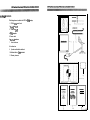
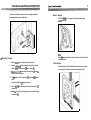
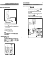
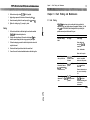
Distributed by
Any reference to Raytheon or
RTN in this manual should be
interpreted as Raymarine.
The names Raytheon and RTN
are owned by the
Raytheon Company.
;
I
Autohelm@
.if
:i
a
.
.
.
-.
_
i
(
WlND & CLOSE
HAULED/WIG
..
Operation and
installation
.
*
c
Ir’
-
ackage Contents
The following items are included in the ST50 Plus Wind package:
1 . ST50 Plus Wtnd control head
2 . Fixing studs (2 offI
3. Thumb nuts (2 oftI
4. Fitting template
5. Power cable
6. Masthead transducer
7 . Control head cover
8. Junction box
9. Operation and Installation handbook
10. Worldwide Service Centre handbook
11. Warranty document
contents
1
.........................................................................
Chapter1:ContmIHeadlnstallation..
.......................................
1.1 Sing ...........................................................................
1.2 Mounting Procedure ........................................................
1.3 Power Supply (stand-alone operation) ..................................
1.4 Power Supply (SeaTalk operation) .......................................
1.5 Connection of Separated Instruments ..................................
1.6 Ring Connection ..............................................................
.3
3
4
.6
6
.7
8
1.7 Connection to SeaTalk Compatible Autopilots ....................... .8
Chapter2:Transd~lnstaUation ............................................
9
2.1 Connection to the Control Head ........................................... 9
2.2 Masthead Transducer Installation ........................................ 9
................................
11
3.1 Fat&Finding.. ..............................................................
.ll
3.2 Maintenance ................................................................
.12
Chaptw3:FaultFindingandMaintenance
chapwkoperation
...........................................................
13
4.1 True/ApparentWlnd Selection .......................................... 14
4.2 Illumination ..................................................................
Chapter 5: CODE Lock Security .............................................
5.1SecurityCode ..............................................................
Chapter 6: Calibration ..........................................................
14
15
15
17
6.1 Initial Calibration ............................................................
18
6.2Extended Cabration ......................................................
20
Chapter7:GeneralSpecitication ............................................
23
Chapter8: CloseHauled)AlG ..............................................
.25
8.1 Package Set .................................................................
25
8.2 Operation .................................................................... 26
,-SC
* 3 ,“,-+&+&. . e... A h”&.+n--..n~ .-. ........................................... ..L”
“.~,II~~,,“““,,U,,“,“,Ul,,~~,l”ll\r~
Introduction
The ST50 Plus Wind instrument features a 360 degree apparent wind scale
and a sensitive yet stable needle drive that delivers accurate information under
even the most demanding conditions.
The unit can be configured to operate as a master or a dedicated repeater unit.
When used as a master the unit displays data received directly from the
masthead transducer, whereas repeater mode displays wind information
already on the SeaTalk bus.
These instruments also incorporate a security feature to protect units
mounted in vulnerable areas, such as the cockpit, helm or mast.
Thank you for purchasing an Autohelm product. May we take this opportunity
to wish you years of trouble free operation.
Chapter 1: Control Head Installation
1lOmm (4.33in)
38.75mm (1.5in)
r-1
I~_24mm10.!35ini
1lOmm
(4.33ird
1.1 siting
The ST50 plus Wind is designed for above or below deck installation
where it is:
l
Easily read by the helmsman
l
Protected against physical damage
l
At least 230mm (9in)from a compass
l
At least 500mm (2Oin) from radio receiving equipment
l
Accessible from behind for ease of installation and cable running.
CUiOll:
To prevent moisture forming on the display window, the unit
‘breathes’through a small vent in the cable boss. Therefore, the
control head must be sited where the rear case is protected from
contactwithwater.
The rear case is fitted with a foam gasket to form a water-tight seal between
the instrument and the selected installation face.
.2 Mounting Procedure
1 . Make sure ibatthe selected location is clean, smooth and flat.
2. Apply the seffadhesiie template (supplied) to the selected location and
mark the centres for the fixing studs (21 and the cable boss (1).
3. Drilltio 4mm(5/32in) clearance holes for the fixing studs (2) through the
bulkhead. Remove the template.
4. Cut the clearance hole for the cable boss (1) using a 50mm (2ir-r) diameter
cutter.
5. Screw the two fixing studs (2) into the control head.
6. Pass the SeaTalk cable and transducer tails through the cableboss (1)
clearance hole.
7. Assemble the control head to the bulkhead and secure from behind using
the thumb nuts (3).
Bracket Mounting
The ST50 Plus Wind can, as an alternative, be bracket mounted using the
Autohelm Mounting Kii.
NO@.?:
Because the instrument breathes through the vent in the rear case, this bracket
is for interior use only.
Flush Mounting
A flush mounting kii is available for installations where a flush mount is required
or more desirable. Full installation instructions are provided with the kit.
1.5 Connection of Separated lnstnments
3 Power Supply (stand-alone operation)
Separated instruments can be connected using one of the range of SeaTalk
Extension Cable. These cables are supplied with a SeaTalk connector fitted to
each end. A junction box can be used to join the cable if it is cut for easier
routing or shortening.
if preferred, any 2 core, screened cable conforming the following specification
may be used instead of the SeaTalk cable.
22 AWG, 2 core screened cable with a minimum copper area of 0.5mm2.
l
5 Amp circuit breaker
12v supply
1 . Connect the 2m (6ft.I power supply cable to the distribution panel.
2 . Cut the cable to length and connect the red wire totbe +12V terminal and
screen to the OV terminal.
3. Cut back and insulate the yellow wire.
I I
4. Protectthe circuitwith a 5Acircuitbreaker.
1 1
Note:
Longer runs to the power supply can be made using the 9m (3Oftl SeaTalk
Extension Cable (D131).
. Power Supply (SeaTalk qperation)
I
I
All instruments in a SeaTalk system receive power and information from the
SeaTalk bus. Each instrument has two SeaTalk connectors (3 pin) on 15Omm
(6in) tails. To supply power and information to the instrument simply plug the
adjacent instrument tails into the ST50 Plus tails.
To transducer
.r a ,
SeaTalk tails
I
SeaTaik
tails
~,,3i
Junction
box
I\ 1
r
’
Yellow
1
‘-1 Screen-J L Red -I Ucreen
1
I
I
“llll
i
cTllapm2:Twm
Chapter 2: Transducer Installation
Installations with a large number of instruments on a SeaTalk bus may require
a second riigmain connection to the power supply breaker to prevent
excessive voltage drops. Whether a second ring main is required can be
determined from the following:
Cable run upto 1Orn (33ft)
Single connection:
13 instruments maximum
Secofd connection:
26 instruments maximum
7 instruments maximum
Second connection:
13 instruments maximum
The ST50 Plus Wind is supplied with a transducer cable tail and connector
which simply plugs into the 30m f10Ofbiransducer cable.
2.2 Masthead Transducer Installation
n
Cable runupto 20m (66ft)
Single connection:
2.1 Connection to the Control Head
The second ringmain should be connected to the spare lead on the last
instrument in the chain and directed back to the circuit breaker.
Connection to SeaTalk Compaljble Autopilots
lf the installation includes a SeaTalk compatible Autopilot fhe ST50 instru
ments may be connected to the SeaTalk bus at any point. No independent
connection to the 12V power supply is necessary as the instruments receive
power from the Autopilot course computer.
For best performance the mounting block must be fixed to a horizontal
surface. lfthe mast top is not horizontal, make up a wedged packing piece (1).
To autopilot
SeaTalk BUS
Connection
To any further
ST50 Instruments
or Autopilot
Control Units
D1134-
1 . W~the~readedendofthemountingblock(2)facingfoMlards,markthe
position of the two self-tapping screws.
Chapter 3: Fault Finding and Maintenance
2. Drill two holes using the 4mm (5/32in) drill bii (supplied).
Chapter 3: Fault Finding and Maintenance
3 . Apply sealing compound to the bottom of the mounting block (2).
4.
3.1 Fault Finding
Secure the mounting block to the mast top using the two screws (4).
5. Tighten the locking ring (3) securely by hand.
Cabling
1 . Cut the cable so that there is sufficient length to run from the masthead
iransducer to the below deck junction box.
2. Feed the cable down the mast -if the mast is deck stepped the cable
should be passed through the deck using a proprietary deck gland.
f
I
All Autohelm products are, prior to packing and shipping, subjected to
comprehensive test and quality assurance programmes. However, if a fault
arises with the ST50 Plus Wind, the following table will help to identify the
probable cause and provide the most likely cure.
Fault
Cause
Action
Instrument display
blank.
No supply.
Check supply.
Check cabling and
security of SeaTalk
connectors.
3 . To allow for unstepping, connect the cable to the junction box close to its
entry into the vessel.
4. Run the cable from the junction box back to the control head.
Check fuse/breaker.
5. Connect the control head and masthead transducer cable tails together.
Return unit for repair.
CL is displayed when
unit is powered on.
CODELOCK security
system has been
activated.
Correct code number
must be transmitted
before unit will operate
SeaTalk cabling
No exchange of
information between
problem.
SeaTalk instruments fie,
illumination levels).
Check security of
SeaTalk connectors.
SeaTalk
Failure of a group of
instruments in SeaTalk cabling/connector
chain.
problem.
Check security of
SeaTalk connectors
between functioning and
non-functioning
instruments.
Remove instruments one
by one to isolate faulty
unit.
ST50 plus Wind & Close Hauled,MWG
Operation and Installation Handbook
! Maintenance
Chapter 4: Operation
Instrument
Certain atmospheric conditions may cause condensation to form on the
control head window. This will not harm the instrument and can be cleared by
increasing the illumination setting to Level 3.
Chemical and abrasive materials must not be used to clean the ST50 Plus
Wind instrument; if it is dirty, clean with a soft, damp cloth.
Transducer
Apply silicone grease to the mounting block and transducer contacts every
season.
Always remember to remove the masthead transducer when stepping or
unstepping the mast.
Cabling
Examine all cables for chafing or damage to the outer shield and, where
necessary, replace and resecure.
Advice
For advice, or further information regarding the installation of this product,
please contact the Autohelm product Support Department or your own
National Distributor.
The ST50 Plus Wind can be used as a standalone unit or, when connected
to other SeaTalk instruments, part of a fully integrated instrumentation
system. This integrated system can then be linked to any of the Autohelm
SeaTalk compatible autopilots.
When the unit is powered-up apparent wind speed and angle or true wind
speed and angle will be displayed, depending on the last selection prior to the
power being turned off.
If the < > key is pressed while in this mode, the TRUE or APP (apparent)
legend will flash to indicate a maximum recorded reading. Also, a 1 second
press and hold of this button will return the display to the current reading.
ST50 Plus Wind 81 Close Hauled,NMG
Operation and installation Handbook
True/Apparent Wind Selection
Chapter 5: CODE Lock Security
PressCAL momentarily to alternate (toggle) between true or apparent wind.
Once selected a solid marker appears above the selection.
CAL
I
D
arent wind speed and direction
True wind speed and direction
0246
Note:
If vessel speed is not available on the SeaTalk bus when true is selected, the
LCD will display a series of dashes and the pointer will continue to show the
apparentwind direction.
5.1 Secubty Code
The ST50 Plus range of instruments is equipped with a security code feature
(called ‘CODE Lock’) to protect your system against possible theft. Entered
using the keypad on digital instruments, this is a four figure number of your
choice that can be entered at every power-up or, alternatively, transmitted
automatically on the SeaTalk bus when there is a secure belowdecks master
instrument.
The analogue ST50 Plus Wind will only respond to transmissions on the
SeaTalk bus -a security code cannot be entered from this unit. Once a security
code has been transmitted to this unit itwill not operate until the correct code
number has been received from the master instrument.
Please refer to a digital instrument handbook for complete details on the
CODE Lock security system.
Illumination
The ST50 Plus Wtnd has three levels of illumination plus off.
1 . PressCAL for 1 second to display the current illumination level.
Correct security code received
2. PressCAL within 8 seconds to selectthe required level: L3 High, L2
Medium, Ll Low and LO off.
Note:
The LCD display will return to normal operation 8 seconds after the last key
press.
incorrect security code or
master missing
DLlll
17
Cha@rG:-
Chapter 6: Calibration
The ST50 Plus Wind must be calibrated before it is used for navigational
purposes. Also, as it leaves the factory the instrument is setwith units in knots,
zero wind angle off set, and damping set at 4 seconds. These settings can be
adjusted as described in the following sections.
19
cThpterS:-
Initial Calibration
Windspeed Unit Selection
1.
Windvane Alignment
Press and hold CAL until Ul (Knots) or U2 (Metres/secondl is displayed.
Before the unit is used for navigational purposes the masthead transducer
must be accurately aligned to thevessel. Before this procedure is carried out
the windvane should be linearised as follows.
1 . Powerup lhe ST50 Plus Wind instrument.
2. Tumthevessel through two complete circles, making sure that the
windvane remains in line with the wind -the instrument will automatically
linearise the windvane.
Alignment
2. Press CALwithin 8 seconds to change the windspeed units selection.
1. Press and hold CAL for 2 seconds until CO is displayed by the LCD.
3. After 8 seconds the wind instrument returns to normal operation.
2. Press < > to move the pointer to the correct wind angle.
-
WIND
l
Press < > once to move the pointer by 1 degree.
l
Press < > for 1 second to move the pointer by 10 degrees/second.
NOk
The LCD will now display the applied correction.
3. Press and hold CAL for 2 seconds to exit and store windvane alignment.
Chapter
6:
Calibration
Extended Calibration Notes
Extended Calibration
Boat Show Mode
Boat show mode ‘S’ is a dealer demonstration program only. Under no
circumstances must this program be engaged when this unit is installed on
your vessel.
display must, therefore, always be set to ‘SO’ (inactive).
r\ firen w--..L
l3ulkdEgle Damping
Apparent wind angle damping is identified by an upper case ‘H’ and a number
between 1 and 9 (seconds).
Apparent Wind Speed Damping
Apparent wind speed damping is identified by an upper case ‘J’ and a number
between 1 and 9 (seconds).
True Wind Speed Damping
True wind speed damping is identified by a lower case ‘c’ and a number
between 1 and 9 (seconds).
APPARENT WIND
DAMPING
APPARENT WIND
SPEED DAMPING
TRUE WIND
SPEED DAMPING
TRUE WIND
ANGLE DAMPING
The options in extended calibration are changed using the < > rocker key.
True Wind Angle Damping
True wind angle damping is identified by a lower case ‘d’ and a number
between 1 and 9 (seconds).
ST50 plus Whd & Close Ifaulad~G Operadon
and lnsta~ladm Handbook
Chapter 7: General Specification
Dimensions:
110x11omm(4.33x4.33m)
Power supply:
10to16v
Power consumption:
70ma (normal) lOOma (illumination on)
Temperaiure range:
oto7odeg.c
PQparentwind speed:
Oto99knotsorme~es/sec
Apparent wind angle:
Oto18Odegreesportorstarboard
calculations:
TruewindangleOto18Odegreesportor
Starboard
Truewindspeedknotsormetres/sec
Maximum wind speed, apparent or true
UIitS:
software
Damping:
ltol5seccxlds
Repeater capability:
Software
Im:
3k?velsplusoff
programmable
programmable
Chapter8: Close Hauled/VMG
The ST50 f%s Close Hauled,AMG provides an expanded close hauled
display~2oto6oqonthedial.whenboatspeedinformationisavailableonthe
SeaTaikbustheLCDprovidesacontinuousreadoutofVelociiMadeGood
WAG).
/
8.1 Package Set
lheST5OPlusCloseHauled/VMGpackagecomprisesofthefollowingitems:
1. ST5OPlusCloseHa&QVh4Gcontrolhead
2. Fixing studs
3. Thumbnuts
4. Ftingtempbte
5. Operation and installation handbook
6. WoddwideServiceCentrehandbook
7. Warrantydocument
_
.:.-!
..:.
.
8.2 Operation
ThelefthandbuttonQamp)isusedtotumtheillwninationonandoff,whilethe
rigMhandbuttonisadummywithoutany~on.
There are four ilhnination settings: L3 0&jhtestI, L2, Ll and LO (off).
8.3 lnstaMion and Maintenance
Control head installation and maintenance procedures are identical to the Wind
unitPleaserefertotherelevantsectionsin~shandbodc.
_
.
.
.
.
.:
I
.
!
.
- .
81016.1
:
!-<
.,