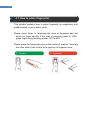
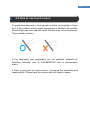
1
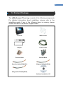
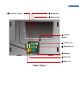
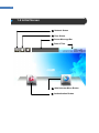
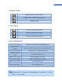
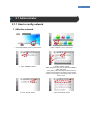
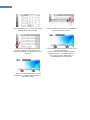
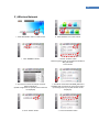
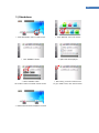
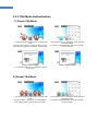
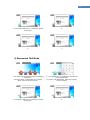
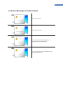
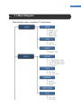
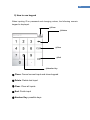
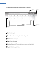
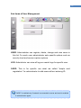
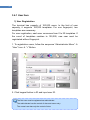
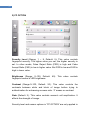
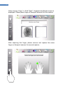
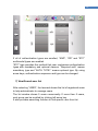
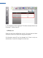
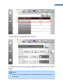
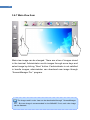
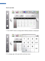
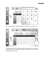
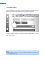
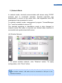
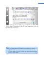
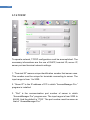
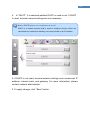
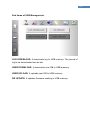
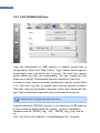
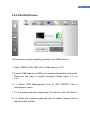
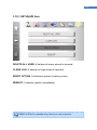
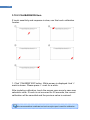
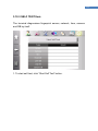
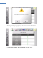
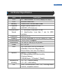
2 © Copyright 2013, NITGEN&COMPANY Co., Ltd. All rights reserved. ` Unauthorized reproduction of part or all of this manual’s content in any form is prohibhited. Product specification may change whithout prior notice to improve functionality. NITGEN&COMPANY and NITGEN logos are registered trademarks of NITGEN & COMPANY. Other names and trademarks belong to resprective companies. NITGEN & COMAPY Customer Service Center Tel: +82.2.513.2147 Fax: +82.2.513.2191 Email: [email protected] ` 3 Table of Contents CHAPTER 1 .................................................................................................. 4 GETTING STARTED .................................................................................... 4 1.1 PRODUCT INTRODCUTION ...............................................................................5 1.2 PRODUCT PACKAGE ......................................................................................6 1.3 PRODUCT DETAIL ..........................................................................................7 1.4 INITIAL SCREEN .............................................................................................9 CHAPTER 2 .................................................................................................11 BASIC OPERATIONS .................................................................................11 2.1 ADMINISTRATOR ..........................................................................................12 2.2 NORMAL USER ............................................................................................26 CHAPTER 3 ................................................................................................ 37 ADMINISTRATOR MENU ........................................................................... 37 3.1 MENU DIAGRAM ..........................................................................................38 3.2 MENU USAGE .............................................................................................41 3.3 ADMINISTRATOR REGISTRATION ....................................................................46 3.4 USER MANAGEMENT ....................................................................................49 3.5 AUTHENTICATION OPTIONS ...........................................................................69 3.6 SYSTEM MANAGEMENT ................................................................................80 3.7 NETWORK OPTIONS .....................................................................................96 3.8 USB MANAGEMENT ..................................................................................105 3.9 EXTERNAL CONNECTION ............................................................................ 112 3.10 INITIALIZATION ......................................................................................... 118 CHAPTER 4 APPENDIX ........................................................................... 124 4.1 HOW TO PLACE FINGERPRINT ......................................................................125 4.2 HOW TO USE TOUCH SCREEN ......................................................................126 4.3 TROUBLESHOOTING ...................................................................................127 4.4 PRODUCT SPECIFICATION ...........................................................................130 4 Chapter 1 Getting Started 1.1 Product Introduction 1.2 Product Package 1.3 Product Detail 1.4 Initial Screen ` 5 1.1 Product Introdcution The eNBioAccess-T5 Access Control Terminal developed by NITGEN combines core technologires such as fingerprint recoginition algorithms, robust optical sensors, embedded system design, and application programs. The eNBioAccess-T5 allows administrator to remotely monitor and manage geographically dispersed terminals efficiently. User-friendly software Biometric Ergonomic technology Design For easy interactive interface, the eNBioAccess-T5 has 4.3” Touch TFT-LED screen. It provides not only fingerprint recognition, but also various authentication methods and combination. 6 1.2 Product Package The eNBioAccess-T5 package consists of the following components. For detailed information about installation, please refer to the installation guide. If any of the following items is missing, please contact NITGEN “Cumstomer Support Team”. Terminal Wall Bracket Adaptor Power Cable Terminal Bolts Bracket Bolts Door/Aux Cable(6PIN)-2EA Wiegand IN Cable(5PIN) Wiegand OUT Cable(4PIN) Software Installation CD ` 7 1.3 Product Detail ① Touch Screen LCD ② Camera ③ Status LED Blue: Stand-by Green: Success Red: Fail ④ Fingerprint Scanner ⑤ Card Scanner < Front View > ① Reset Button ② USB Port ③ Speaker < Bottom View > 8 ① Door/Aux Jumper ② Wiegand In ③ Battery Area ④ Tamper Switch ⑤ Power Con. ⑥ Wiegand Out ⑦ Network ⑧ Aux Con. ⑨ Door Con. < Rear View > ` 9 1.4 Initial Screen ① Network Status ② Door Status ③ Server Message Bar ④ Date & Time ⑤ Administrator Menu Button ⑥ Authentication Button 10 ① Network Status Network mode, Connected to server Network mode but not connected to server Standalone Mode ② Door Status Door1 is used and is now closed Door1 is used and is now opened Door2 is used and is now closed. Server Message Bar Terminal is not registered in “AccessManager Pro” Terminal not registered MAC Address not There is a terminal having same ID in “AccessMaanger Pro” matched User count not matched The number of user is different with server Download user from Server is downloading users. server Update user from server Server is updating user’s status. Set option from server Server is seting options for terminal. Delete user from server Server deletes an user. Delete all from server Server deletes all users. eNBioAccess-T5 is supported inAccesssManager Professional V1.2.0.0(file version 1.2.1.0) or above. ` 11 Chapter 2 Basic Operations 2.1 Administrator 2.2 Normal User 12 2.1 Administrator 2.1.1 How to config network 1 ) Wireline network ⒜ Click administrator menu in initial screen ⒝ Click “Network” icon in sub menus. ⒞ Click “NORMAL” Button. ⒟ Select “wireline” button. Data encryption mode can be selected as DES or AES_256 mode. If any option value is changed, please click left bottom “Save” button to maintain current values. If there is no changed, click “Back” button to go to above menu. ⒠ Click “TCP/IP” button. ⒡ Click “Terminal ID” button. ` 13 ⒢ Input terminal ID from 1 to 2000. Do not input the same ID with other terminal. ⒣ Input IP address of PC used as AccessManger server and click “OK” button. ⒤ Above shows the display after setting. To save configuration, click “Save” button. (When setting “DHCP” off, please refer to “3.7.2 TCP/IP”). ⒥ Connect LAN cable to network connector in the back of the terminal. Network status shows unregistered terminal. Register terminal in “AccessManager Pro” (For more information, please refer to “AccessManager Pro user guide”) ⒦ After successfully registering in “Access Manager Pro.”, network status changed to registered terminal. 14 2 ) Wireless Network ⒜ Click administrator menu in initial screen. ⒝ Click “Network” icon in sub menus. ⒞ Click “NORMAL” Button. ⒟ Select “wireline” button. Data encryption mode can be selected as DES or AES_256 mode. Click “AP list” ⒠ The above is shows the sample of AP list. Select wireless AP. (If WIFI dongle does not operate, AP list does not be displayed) ⒡ The above shows when NITGEN_RND AP is seledted. After re-confirm AP, click “Save” button. (According to AP, key request window can be displayed). ⒢ Click “TCP/IP” button.. ⒣ Click “Terminal ID” button. ` 15 ⒤ Input terminal ID from 1 to 2000. Do not input the same ID with other terminal. ⒥ Select “Server IP”, keypad will be displayed. To input number, click “Num” button. ⒦ Above shows the display after setting. To save configuration, click “Save” button. (When setting “DHCP” off, please refer to “3.7.2 TCP/IP”). ⒧ Network status shows unregistered terminal. Register terminal in “AccessManager Pro” (For more information. Please refer to “AccessManager Pro user guide”). ⒨ After successfully registering in “Access Manager Pro.”, network status changed to registered terminal. To use wireless network, WIFI dongle must be included in the terminal. WIFI dongle is an optional component. AP means Access Point that can supports wireless network. 16 3 ) Standalone ⒜ Click administrator menu in initial screen. ⒝ Click “Network” icon in sub menus ⒞ Click “NORMAL” Button. ⒟ Option lists are displayed. ⒠ Select “Disable” button. Click “Save” button to maintain current values. ⒡ After saving, it moves to above menu. To go to initial screen, click “Home” button. ⒢ Network status shows standalone terminal ` 17 2.1.2 How to add user 1 ) Administrator Registration Fingerprint Only ⒜ Click administrator menu in initial screen. ⒝ Click “User” icon in sub menus ⒞ Click “USER” butoon. ⒟ To add new user, click “+” button. ⒠ Registration scrren is displayed. The first user will be registered with master privilege Select “ID” input window. ⒡ ID keypad is displayed. ⒢ After inputing ID, click “OK” button. The default ID length is 4. (The ID length can be changed. For more information, please refer to chapter 3.6.4.) ⒣ In “AUTH TYPE1” select “Finger”. (For more information, please refer to chapter 3.4.1.) 18 ⒤ Select the finger you wish to register. ⒥ The terminal requires fingerprint twice. Place your finger on the scanner after voice instruction. ⒦ The terminal displays fingerprint image. After capturing first image, please remove the finger and replace the same finger. ⒧ The above displays screen when fingerprint is successfully captured twice. ⒨ Click ‘Save” button. (10 fingerprints can be saved for each ID.) ⒩ If fingerprint is registered successfully, “Finger” button is changed with blue mark. Click ‘Save” button to finish registration. The above image shows the registration of ID “1234” with only fingerprint. ⒪ It shows that ID “1234” is added. In network mode, user can be added by using “AccesssManager Pro.” ` 19 2 ) Normal User Registration Password Only ⒜ Click administrator menu in initial screen ⒝ Click “User” icon in sub menus ⒞ Click “USER” butoon. ⒟ To add new user, click “+” button. ⒠ Registration scrren is displayed. The first user will be registered with master privilege Select “ID” input window. ⒡ ID keypad is displayed ⒢ After inputting ID, click “OK” button. The default ID length is 4. (The ID length can be changed. For more information, please refer to chapter 3.6.4.) ⒣ In “AUTH TYPE1” select “Passwordr”. (For more information, please refer to chapter 3.4.1.) 20 ⒤ Keypad for password is displayed. ⒥ After inputing password, click “OK” button. To confirm password, please input password again. ⒦ If password isregistered, “Password” button is changed with blue mark. Click ‘Save” button to finish registration. The above image shows the registration of ID “0001” with only password. ⒧ shows that ID “0001” is added. ` 21 2.1.3 How to delete user 1 ) How to delete single user ⒜ Click administrator menu in initial screen ⒝ Click “User” icon in sub menus ⒞ Click “USER” button. ⒟ Select user to be deleted. In example, ID”0001” is selected. ⒠ Click “Wastebasket” icon to delete. ⒡ The above warning message is displayed. To continue, click “Yes” button. ⒢ It shows that ID “0001” is deleted. 22 2 ) How to delete all users ⒜ Click administrator menu in initial screen ⒝ Click “Initialization” icon in sub menus ⒞ Click “INITIALIZE” button. ⒟ Click “DELETE ALL USER” button. ⒠ The above warning message is displayed. To continue, click “Yes” button. ⒡ After deleting all users, above message is displayed. To Continue, click “OK” button. ⒢ To check the deletion of all users, select “System” icon in top line. ⒣ Click “INFORMATION” button. ` 23 ⒤ It shows “User/Template” and “Admin” count as ‘0’. 24 2.1.4 How to change options 1 ) How to config Door The following example shows how to config door to open when authentication succeeds. ⒜ Click administrator menu in initial screen. ⒝ Click “External Connection” icon in sub menus ⒞ Click “DOOR” button. ⒟ In this screen, select whether to use or not. Click “Right Arrow” button. ⒠ In this screen, when to open door can be selected. The default is that door1 is configured as to open door when ahtuentication succeeds. ⒡ As configured correctly, Successful authentication displays popped-up window and door-open icon in initial screen. eNBioAccess-T5 supports two doors. ` 25 2 ) How to config T&A ⒜ Click administrator menu in initial screen. ⒝ Click “Authenticiation Management” icon in sub menus ⒞ Click “T&A” button. ⒟ Select T&A mode from Simple/Normal/Expanded/Auto TNA. (For more information, refer to chapter 3.5.2.) ⒠ After selecting T&A type, “T&A Auth Only” table is enabled. If this option is enabled, authentication with function key is only possible. To maintain configuration, click “Save” button. ⒡ To quit menu, click “Home” button. . ⒢ The initial screen is changed. New icons for T&A are added. 26 2.2 Normal User 2.2.1 Authentication There are two authentication mode – 1:1 verficiation and 1:N identification. For 1:1 verification, an user inputs ID and try to authenticate. For 1:N identification, an user try to authenticate without ID. For more information, please refer to chaper 3.5.1. 1 ) 1:1 Verification (A) Fingerprint authentication ⒜ For 1:1 verifiation, click “Authentication” icon in initial screen. ⒝ The keypad for ID is displayed. ⒞ Input user ID. ⒟ Fingerprint request window is pop-uped. Place finger to scanner. ⒠ Fingerprint image is captured. ⒡ If succeeded, the welcome window is pop-uped. ` 27 (B) Password Authentication ⒜ For 1:1 verifiation, click “Authentication” icon in initial screen. ⒝ The keypad for ID is displayed. ⒞ Input user ID. ⒟ The keypad for password is displayed. ⒠ Input password. ⒡ If succeeded, the welcome window is pop-uped. 28 2 ) 1:N Identification (A) Fingerprint Authentication ⒜ Place finger on the scanner in initial screen. ⒝ Fingerprint image is captured. ⒞ If succeeded, the welcome window is pop-uped. (B) Card Authentication ⒜ Place card on card scanner in initical screen. ⒞ If succeeded, the welcome window is pop-uped. ⒝ The card request window is pop-uped. ` 29 2.2.2 Multimodal Authentication 1) AND Method AND method is used to combine more than two authentication types to authenticate users only if all of types are satisfied. The following example explains how to authenticate user having “Fingerprint AND Password” multimodal method. ⒜ For 1:1 verifiation, click “Authentication” icon in initial screen. ⒝ The keypad for ID is displayed. ⒞ Input user ID. ⒟ Fingerprint request window is pop-uped Place finger to scanner. ⒠ Fingerprint image is captured. ⒡ If succeeded in fingerprint authenticataion, the keypad for password is displayed. 30 ⒢ Input password. ⒣ If succeeded, the welcome window is pop-uped. 2) OR Method OR method is used to combine more than two authentication types to authenticate user if any of type is satisfied. The following example explains how to authenticate user having “Password OR Card” multimodal method. ⒜ For 1:1 verifiation, click “Authentication” icon in initial screen. ⒝ The keypad for ID is displayed. ⒞ Input user ID. ⒟ The keypad for password is displayed. ⒠ Input password. ` 31 (A) If correct password is used, ⒡ succeeded, the welcome window is pop-uped. (B) If password is wrong, The terminal fails to authenticate user and requests card accoriding to predefined multimodal method. ⒡ The card request window id pop-uped. Place card on card scanner. ⒢ If succeeded, the welcome window is pop-uped. 32 3) ETC In this mode, administrator can sort authentication types to the mandatory and the optional. “Required auth” column means mandatory types and “AUTH TYPE1” means optional types. User must satisfy all of mandatory types and any of optional types. (If there is only one optional type, it must be satisfied). The following table explains some examples. ⒜ The mandatory types are card, password and fingerprint. Three authentication types must be satisfied in the following sequences “Card password fingerprint” ⒝ Authentication is granted if any of optional types such as card, password and fingerpint is to be satisfied. The option types are tried as the following sequence is “Card Fingerprint Password”. ⒞ Mandatory type: Fingerprint Option type: Card Password Fingerprint must be authenticated before trying to authenticate card or password. Option types are tried aso the following sequence “Card Password”. ⒟ Mandatory type: Card Password Optional type: Fingerprint Card and password must be authenticated as the following sequence “Card -> Password”. After that, fingerprint is authenticated. Fingerprint is only optional type, it must be satisfied. ` 33 2.2.3 T&A Mode Authentication 1) Simple T&A Mode ⒜ The above image is initial screen in simple T&A mode. The left icon is used for “Coming to Work”. On the other hand, the right icon is used for “Leaving work” ⒝ For password or 1:1 verification, Input user ID to be authenticated. For card or 1:N identification, place card or finger on each scanner. ⒞ If succeedd, “Welcome” or “Good-bye” window is pop-uped. ⒟ 2) Normal T&A Mode ⒜ The above image is initial screen in normal T&A mode.. “Coming to Work”, “Going Out”, “Comming Back”, and “Leaving Work” icons are shown from left. ⒝ For password or 1:1 verification, Input user ID to be authenticated. For card or 1:N identification, place card or finger on each scanner. 34 ⒞ If succeedd, “Welcome” or “Good-bye” window is pop-uped. ⒟ ⒠ ⒡ 3) Expaneded T&A Mode ⒜ The above image is initial screen in expaneded T&A mode.. “Coming to Work”, “Expaneded”, and “Leaving Work” icons are shown from left. ⒝ ⒝ For password or 1:1 verification, Input user ID to be authenticated. For card or 1:N identification, place card or finger on each scanner. ⒞ If succeedd, “Welcome” or “Good-bye” window is pop-uped. ⒟ ` 35 ⒠ When selecting “Expanded” icon, user can input function key number from 1 to 98. The above image shows an example of ‘24’. ⒢ The result of expanded T&A can be checked in log. The above image shows the examplel log of (e). Funckey value is ‘24’. (For more information about log, please refer to chapger 3.4.2.) ⒡ If succeedd, result window is pop-uped. 36 2.2.4 Error Message of Authentication ⒜ ID does not exist. ⒝ Authentication fails. ⒞ The terminal does not finish capture fingerprint during pre-defined time. of ⒟ The terminal does not get password or card during pre-defined time. ` 37 Chapter 3 Administrator Menu 3.1 Menu Diagram 3.2 Menu Usage 3.3 Administrator Registration 3.4 User Management 3.5 Authetication Options 3.6 System Management 3.7 Network Options 3.8 USB Management 3.9 External Connection 3.10 Initialization 38 3.1 Menu Diagram Administrator menu consists of 7 sub-menus. ` 39 40 ` 41 3.2 Menu Usage After entering administrator menu, Sub-menus are displayed as icons and each sub-menu has several lists. For intuitive and easy interface, lists are displayed when each sub-menu is selected. And for easy switching, sub-menus are shown in top area of screen. ① Home Button ② Sub Menus ③ Lists ④ Save Button ⑤ Back Button 42 ① Home Button: Going to initial screen regardless of current position. ② Sub Menus: Switching to other sub menus ③ Lists: A group of items of selected sub-menu. ④ Save Button: It is activated when current configuration is changed. To maintain changed configuration, click this button. ⑤ Back Button: Going to above stage. ` 43 1) How to change value ① If the change of option is possible, a related button is activated. To change, click button. The current value is displayed as blue color or blue dot. ② If the value you want is shown, click number to select. If not, click arrow to find value. 44 2) How to use keypad When inputing ID or password and changing values, the following numeric keypad is displayed. ①Close ②Delete ③Clear ④End ⑤Number Key ① Close: Cancel current input and close keypad ② Delete: Delete last input ③ Clear: Clear all inputs ④ End: Finish input ⑤ Number Key: possible keys ` 45 For alpha-numeric keypad, the following keypad is displayed. ①End ④Clear ⑤Number/Alpabet ⑥Capital ① End: Finish input ② Close: Cancel current input and close keypad ③ Delete: Delete last input ④ Clear: Clear all inputs ⑤ Number/Alphabet: Change between number and alphabet ⑥ Capital: Switch capital letter ②Close ③Delete 46 3.3 Administrator Registration Administrator has the right to change system options, manage users, and enter the administrator menu. The first user will be registered as administrator. Administrator can be added in terminal or “AccessManger Pro.”. ⒜ Click administrator menu in initial screen. If there is no user, anyone can enter administrator menu ⒝ Click “User” icon in sub menus. ⒞ Click “USER” butoon. ⒟ To add new user, click “+” button (E) Registration screen is displayed. The first user will be registered with master privilege Select “ID” input window. ⒡ ID keypad is displayed. ` 47 ⒢ After inputting ID, click “OK” button. The default ID length is 4. (The ID length can be changed. For more information, please refer to chapter 3.6.4.) ⒣ In “AUTH TYPE1” select “Finger”. (For more information, please refer to chapter 3.4.1.). ⒤ Select the finger that you wish to register. (j) The terminal requests fingerprint twice. Place your finger on the scanner after voice instruction. ⒦ The terminal displays fingerprint image. After capturing first image, please remove finger from scan and replace finger. ⒧ The above displays screen when fingerprint is successfully captured twice. ⒨ ‘Click ‘Save” button. (10 fingerprints can be saved for each ID.) ⒩ If any fingerprint isregistered, “Finger” button is changed with blue mark. The above image shows the registration of ID “1234” with only fingerprint. To config timezone and authentication options, click right arrow. 48 ⒪ “TIMEZONE” and “FP Option” are applied to current regiatration user. For timezone, Select configration from 1 to 16. ‘0’ means disable. ⒬ To finish configuration, click ‘Save” button. It moves to above screen. New user ID “1234” is added to list. ⒫ If “FP OPTION” is seletected, security level, and sensor options such as brightness, contrast, and gain are selected. ` 49 3.4 User Management In user management menu, adminstirator registration/delete/change, check users and logs. controls user To enter “User Management”, click “USER” icon in administrator menu. 50 Sub items of User Management USER: Administrator can register, delete, change and view users in this list. For each user, administrator sets specific options such as security level and sensor capture options. LOG: Adminitrator can view all logs or search logs for specific user. CARD: This is for specific use what we called “simple card registration” for administrator to add users without entering ID. “CARD” is enabled only if network is connected to server and card is enabled in authentication types. ` 51 3.4.1 User Item 1) User Registration The terminal has capacity of 100,000 users. In the limit of user capacity, it supports 100,000 templates. For one fingerprint, two templates are necessary. For user registration, each user consumes from 0 to 20 templates. If the count of templates reaches to 100,000, new user must be registrated without fingerpint. 1. To registration users, follow the sequence “Administrator Menu” “User” Icon “+” Button. 2. Click keypad button in ID and input user ID. The first user must be registered as administrator. The administrator has the control of door and menu entry. The normal user has only the control of door. 52 3. Select privilege of user – administrator or normal. 4. If selecting “Use Custom”, administrator can change security level and sensor capture options such as brightness, contrast, and gain. Normally, the default values are used. The custom setting is recommended to be used restrictly for wet or dry finger. ` 53 2) FP OPTION Security Level (Range: 1 ~ 9, Default: 5): This value controls fingerprint security. The higher value you set, the higher security is set. In other words, False Reject Ratio (FRR) is high and False Accept Ratio (FAR) is low in higher value. But FRR is low and FAR is high in lower value. Brightness (Range: 0~100, Default: 40): This value controls fingerprint sensor’s LED brightness. Contrast (Range:0~100, Default: 20): This value controls the contrasts between white and block of image before trying to authentication for enhancing success ratio. ‘0’ means no contrast. Gain (Default: 2): ‘This value controls sensor’s cell ampllication. It affects the strength of image. Security level and sensor options in “FP OPTION” are only applied in 54 1:1 verification. To restore default value, select “Use Default” and click “Save” button. 5. More than one of “Auth Type1” must be selected. For multimodal authentication, select type in “Auth Type2” 3) Fingerprint Enrollment ` 55 When selecting “Finger” in “Auth Type1”, fingerpint enrollment screen is displayed. Please place finger on finerprint scanner for first capture. After capturing first finger, please remove and replace the same finger on finerprint scanner for second capture. 56 If the fingerpint enrollment is finished successfully, green dot glows on finger. To cancel finger, click green dot to disable. Please click “Save” button to save current fingerprint. 4) Password Enrollment When selecting “Password” in “Auth type1”, numeric keypad is poped-up. Please input password (from 4 to 8 digits) and click “OK” button. ` 57 5) Card Enrollment When selecting “Card” in “Auth Type1”, card request image is displayed. Please contact card on card scanner. 6) Multimodal Authentication If more than two authentication types are enrolled, multimodal type can be used. And multimodal type is selected in “Auth Type2”. If “AND” type is seleteted, all of authentication types are satisfied to be granted. On the otherhand, if “OR” type is selected, any of authentication type is used to be granted. 58 If all of authentication types are enrolled, “AND”, “OR” and “ETC” multimodal types are enabled. “ETC” type provides the method that user contomizes authentication types with mandatory and optional classes. “Required auth” means mandatory type and “AUTH TYPE1” means optional type. By using arrow keys, authentication sequence and type can be changed. 7) View/Search user list After selecting “USER”, the terminal shows the list of registered users to help administrator to manage users. The list window shows 5 users concurrently. If more than 5 users, next group can be scrolled by clicking left arrow key. It also provides searching function to find specific user from list. ` 59 1. Administrator can view all users in the list. 2. If more than 5 users, administrator scrolls user list using left or right arrow key. 60 3. To find specific user, click blank list shown as the above image to popped-up numeric keypad and input ID. Partial ID is possible. 4. Click “Search” button to start. ` 61 5. The searching result is displayed. The above example shows user ID having “1” string in their ID. 8) Modify user Select an user to be modified from user list. If an user does not show current list, scroll list or search list using specific pattern. All information except ID can be changed, but if there is only one administrator, it cannot be changed to normal user. 62 1. Click user to be modified from user list. 2. Modify items such as privilege, password, and so on. Click “Save” button. Caution If there is only one administrator, the administrator cannot be changed to normal user. ` 63 9) Delete user The terminal processes deleting user in the same way processing modifying to protect user from being deleted by mistake. Click user from user list and click wastebasket. The warning window is pop-uped. To continue, click “OK” button. 64 3.4.2 Log Item The authentication result is saved in the terminal as log data for future use. Log data consists of log-type, result and time. By selecting log, more information can be viewed such as who is authenticated, which type of authentication is used and so on. 1. To enter “Log Management”, click “LOG” icon in user mangement sub-menu. ` 65 Log list shows the basic information such as log-type, result and time. To find specific data log, click block window above log list and input the date. To check more information of log, click log. The above image shows detail information of one log. 66 3.4.3 Card Item This function is for administrator to register users with card. In this registration, a terminal does not require other information. This is for special case when administrator wishes to add many users having cards. These users are registered with auto-gernerated ID and also viewed in user list. 1. Click “LOG” icon in user mangement sub-menu. “CARD” is enabled only if network is connected to server and card is enabled in authentication type. ` 67 2. Present the card on card scanner when card request image is displayed. User ID is generated automatically. 3. User registered by simple card mode can be viewed in user list, but name is blank. 68 4. To authenticate, present the card on card scanner. ID is gernerated from “0000”. If there is user having same ID, ID is increased to find blank ID. Simple card registration is only available in network mode ` 69 3.5 Authentication Options In this menu, administrator can change options for authentication, sensor options for system, T&A mode, and Card type. 70 Sub Items of Authentication Options Default: In this item, administrator can set terminal security level, the use of 1:N identification, and 1:N timout. T&A: In this item, administrator can set T&A mode. CAMERA: In this item, administrator can control the use of snapshot camera and snapshot display. TIMEZONE: Administrator can view current timezone setting and timezone information. ETC: Administrator can configure the save of log and the operation of result pop-up window. ` 71 3.5.1 Default Item In this item, Administrator can set authentication base operation config such as terminal security level for 1:1 verification and 1:N identification, the use of 1:N identification, and 1:N timeout. Security Level This value is used as the threshold to decide whether fingerprint is granted or not. There are two security level for 1:1 verification and 1:N identification. The input range for 1:1 verification is from 1 to 9 and the default value for 1:1 verification is 5. The input range for 1:N identification is from 5 to 9 to prevent from high false acception and the default valule for 1:N indentification is 8. Security level has the trade-off between FAR and FRR. The lower security value you set, the higher FAR will show. And the higher seucurity level you set, the higher FRR will result. We would recommend the default value if there is no inconvenience. 72 1:1/1:N Authentication options The eNBioAccess-T5 provides two fingerpint authentication methods such as 1:1 verfication and 1:N identification. For 1:1 verfication, ID must be input before authenticating fingerprint, while for 1:N identification, ID does not need to authenticate fingerpint. Normally 1:1 is used for speeding up authentication, and 1:N is used for easy authentication. This is for administrator to prevent 1:N identification for specific application. To disable 1:N identification, select “Not use” button and save. SID SID is an acronym which stands for Short ID. Afther inputing the partial of ID, try to authenticate in 1:N identification. It speeds up the authentication by searching users who have the partical string in their ID. The following shows simple example of SID. ① There is an user “1004”. ③ Fingerprint request window is popped-up. Please place finger on the scanner. The terminal searches users having “1” in their ID and try to authenticate finger with their records. ② Input short ID. For example, If user ID is “1234”, input “1” and click “OK” button. ④ It speeds up 1:N indentifcaition using smaller condidates than normal 1:N identification. SID function is only available for fingerprint users. ` 73 1:N Identification Timeout 1:N identification uses similarity sorting method. It sorts out all registered fingerprints template data according to the similarity with current inputed fingerpint. And it searches from most similar templates. The terminal cannot find matching template, it takes long time. To prevent unwanted long searching time, 1:N identication timeout is provided. This value can be set in range from 3 to 9, and the default value is 3. If searching is not finished in 1:N identification time, it result in “Timeout” error. 74 3.5.2 T&A Item In T&A mode, user must click function key before authentication. And the log is transferred to server with information which function key is selected. According function keys, It is recorded as “Coming to Work”, “Going Out”, “Leaving Work”, and “Coming Back” for more efficient T&A How to Configure T&A Type 1. Select “T&A” item in ‘Authentication Options” sub-menu. 2. There are three types in T&A mode – Simple, Normal and Expanded type. Select T&A type. Simple type supports 2 function keys fixed as “Coming to Work” and “Leaving Work”. Normal type supports 4 function keys fixed as “Coming to Work”, “Going Out”, “Coming Back”, and “Leaving Work”. And expanded type supports up to 98 function keys which are freely configured by software. ` 75 3. Enable “T&A Only” for the enterance to be granted only if user is authenticated through T&A mode. 4. Click “Save” button to maintain current configuration. Caution After enabling “T&A Only”, user must select function key before trying to authenticataion. 3.5.3 Camera The terminnal has internal snapshot camera for capturing user according to options. Administrator can define weather camera is used or not and when camera capture snapshot. 76 How to configure camera 1. Select “Camera” item in ‘Authentication Options” sub-menu. 2. In “Capture” mode, select when to capture user’s snapshot. For example, if “Auth success” is selected, the terminal captures user’s snapshot only when authentication is succeeded. 3. “Resolution” supports low (320x240 pixels) mode. 4. If “Display” is enabled, snapshot image is displayed after displaying authentication result. Snapshot image is saved in PC directory “C:\Program Files\AccessManager Professional\log_image” in network mode. This directory can be changed according to the installation environment. ` 77 3.5.4 Timezone Item The terminal provides door access timezone configuration that door can be opened or closed in pre-defined time. User’s timezone can be viewed in “User Management” “USER” item. But, Timezone configuration is only possible through “AccessManager Pro” program. 1. Terminal Timezone: It shows current timezone index ‘0’ as shown above means timezone is disabled. To change or enable timezone, click button and input index. 78 2. The above image shows the example when timezone 1 is viewed. Timezone can be scrolled using left or right arrow key. The allowance table is expressed with hour-base cell. Caution for timezone Timezone can be made up to 16 different types through “Access Manager Pro.”. ` 79 3.5.5 ETC Item Save Log Administrator selects whether log is saved or not after authentication. Logs can be viewed in “USER” icon “LOG” item or “AccessManager Pro.” User Name Administrator selects whether user name is displayed or not in authentication result window. 80 3.6 System Management In this menu, administrator selects main view background image, language, time, sound, and so on for user’s preference. ` 81 Sub Items for System Management DISPLAY: Administrator can select system language and LCD brightness. SOUND: Administrator can select soucnd effect, the use of voice, and the volume. SENSOR: Adminitsrator can configure sensor capture timeout and LFD (Live Finger Detection) level. USER: Administrator can configure user information such as ID length, the number of templates for one finger. INFORMATION: This item shows the current system configuration of terminal. CARD: Administrator can select card type and the use of card. 82 MAIN VIEW: Administrator can change main view background image. TIME & DATE: Administrator can change system time and date. ` 83 3.6.1 Display Item LANGUAGE You can select the system language of a terminal, it affects display language and voice. The terminal supports English, Korean, Chinese, Portuguese, French, Indonesian, Mongolian, Spanish, Thai, Vietnamese LCD Brightness LCD brightness can be set from 10 to 100. The default valuel is 80. The higher value you set, the brighter LCD it shows. 84 3.6.2 Sound Item Sound The sound consists of voice and effect. It selects which sound is played. It provides four modes – “Voice and Effect”, “Only Voice”, “Only Effect” and “Not in use” Volume It controls the volume of sound. It can be set from 0 to 100. And the default is 20. To change value, click icon and input volume. If volume is set to ‘0’, there is no sound regardless of sound mode. ` 85 3.6.3 Sensor Item In this item, administrator can set sensor capture-timeout, LFD level and sensor options such as brightness, contrast, and gain. These valules are system options and are applied to all users except whose options are defined individually. Time out It defines how long sensor waits for fingerpint to quit capturing. It can be set from 3 to 9. And the default is 5 seconds. LFD(Live Finger Detection) Level It defines which level of LFD algorithm is used. 86 Sensor Options These options – Brightness, Contrast, and Gain – are used for fingerpint image tunning. The above shows the default values. We recommend that these default values do not change. If there is any case for changing these values, please contact technical support. ` 87 3.6.4 USER Item In this item, ID length of user can be changed. To change ID length, there must be no users in terminal. Please delete all users before changing ID length of user. The template count is currently fixed to 2. Click what you wish to change or click input keypad. The range of ID length is from 4 to 20. And the default is 4 digits. The template count is currently fixed 2 and disabled. 88 3.6.5 INFORMATION Item Administrator views system information such as terminal ID, network mode, firmware version, OS version, the number of user, the number of template, the number of administrator, T&A mode, and card type. This information is read-only. ` 89 3.6.6 Card Item Administrator can configure the usage of card and card type. 1. To enable card, select “Normal” button. 90 2. If the usage of card is enabled, Select card type. The terminal supports Mifare, EM, HID, and iClass. To use card authentication, card module must be installed in the terminal. ` 91 3.6.7 Main View Item Main view image can be changed. There are a few of images stored in the terminal. Administrator scrolls images through arrow keys and select image by clicking “Save” button. If administrator is not satisfied in bundle images, administrator can download new image through “AccessManager Pro.” program. The image used in main view can be downloaded through “AccessManager Pro.”. But new image is recommended in size 640x480. If not, main view image can be distorted. 92 3.6.8 DATE & TIME Item In this item, Administrator can set system date & time. ` 93 How to set date 1. Click “DATE” button to change date. Monthly calendar is displayed. 2. To change year, click year button and input value. 94 3. To change month, click month button and input value from 1 to 12. 4. Administrator scrolls monthly calendar through left or right arrow keys to find correct month and click date. (The previous or next month is displayed in gray color.) ` 95 How to set time 1. Click “TIME” button to change time. Digital clock is displayed. 2. To change value, click up/down arrow or click number to pop-up numeric keypad. 96 3.7 Network Options eNBioAccess-T5 provides two operation modes – network or standalone. Wireline and wireless(Optional) networks are all supported. ` 97 Sub Items of Network Options NORMAL: Administrator configures network type, encryption type, connection interval and so on. TCP/IP: Administrator sets server IP address, network mask, port, IP addres, DHCP, and so on. 98 3.7.1 NORMAL Item Type Network mode is configured. There are three modes – standalone, wireline, and wireless. Encryption It defines which encryption method is used on data when terminal communicates with server. DES and AES 256bit are supported. Ping time It defines the interval time that terminal checks the connection to server. The range of interval is from 2 to 20. And the default is 10 seconds. If this value is too small, network traffic is increased. AP list This button is enabled only when wireless mode is used. In wireless mode, click this button to select AP (Access Point) from available list. ` 99 1 ) Standalone Mode If external network is not used, terminal operates in standalone mode. All functions are processed through touch-screen interface. 1. Select “Disable” button to operate terminal in standalone. To apply, click “Save” button. In standalone mode, all functions including registration and deletion are processed in terminal. 100 2 ) Network Mode In network mode, terminal communicates with server using TCP/IP protocol and is controlled remotely. Several terminals are manipulated in server at the same time. And registration and DB management are processed in server. To operate network mode, management program “AccessManager Pro.” must be installed in server PC. The terminal operating in standalone mode is also changed to network mode. But users in terminal are deleted when terminal is connected and synchronized with server. (A) Wireline Network 1. To select wireline network, click “Wireline” button. To apply configuration, click “Save” button. To use wireline network, LAN cable must be connected to LAN port in the backside of terminal. ` 101 (B) Wireless Network 1. To select wireless network, click “Wireless” button and click “AP List” to view AP list. 2. The above shows the samples of AP. Select appropriate AP. (If WIFI Dongle is not initialized correctly, blank AP list can be displayed.) 102 3. After selecting AP, the name of AP is displayed. To apply, click “Save” button. (According to the AP, more information such as protection key is required.) To use wireless network, WIFI dongle must be installed in the terminal. This dongle is an option. AP means Access Point and is a device that allows wireless devices to connect to a wired network. ` 103 3.7.2 TCP/IP To operate network, TCP/IP configuration must be accomplished. The necessary informations are the use of DHCP, terminal ID, server IP, server port and terminal network settings. 1. “Terminal ID” means unique identification number that server uses. This number must be unique for terminals connecting to server. The input range is from 1 to 2000. 2. “Sever IP” is the IP-address of PC in which “AccessManager Pro.” program is installed. 3. “Port” is the communication port number of server in which “AccessManager Pro” program use. The input ragne is from 2000 to 65535. And the default is ‘7332’. The port number must be same as that of “AccessManager Pro.” 104 4. In “DHCP”, it is selected whether DHCP is used or not. If DHCP is used, terminal network settings are not necessary. What is DHCP(Dynamic Host Configuration Protocol)? DHCP is a network protocol that is used to configure devices which are connected to a network so that they can communicate on an IP network. 5. If DHCP is not used, terminal network settings such as terminal IP address, subnet mask, and gateway. For more information, please contact network administrator. 6. To apply change, click “Save” button. ` 105 3.8 USB Management The terminal supports USB memory which is used for upgrading firmware, uploading/downloading user DB, and downloading log data. To manipulate log, “log saving” option must be enabled. Downloading log is possible in network and standalone mode. But, uploading/downloading user DB is only possible in standalone mode. To enter “USB Management”, click “USB Management” icon. 106 Sub Items of USB Management LOG DOWNLOAD: It downloads log to USB memory. The period of log to be downloaded can be set. USER DOWNLOAD: It downloads user DB to USB memory. USER UPLOAD: It uploads user DB to USB memory. FW UPDATE: It updates firmware exsiting in USB memory. ` 107 3.8.1 LOG DOWNLOAD Item Logs are downloaded to USB memory in specific period that is configured by “Start” and “Stop” button. “Type” defines which logs are downloaded from logs which are in period. “Not sent log” means newly added log from last downloading. “All logs” means all logs those are in period. Downloaded logs are checked as “sent log”. In network mode, logs are normally transferred to server, so that there is no “Not sent” log. But, in special case such as network problem, “Not sent” logs can be existed in terminal. In this case, download “Not sent” logs to download logs which are not transferred to server. In network mode, all logs are transferred to server. Logs are saved as “SW300_Log.nlg” in root directory of USB memory. If there exists the same name file, postfix “_number” is added to filename such as “SW300_Log_1.nlg”, “SW300_Log_2.nlg” and so on. The “.nlg” file can be loaded in “AccessManager Pro.” program. 108 3.8.2 FW UPDATE Item The terminal provides updating firmware from USB memory. 1. Save “SW300_Cab.CAB” file to USB memory in PC. 2. Connet USB memory to USB port located in the bottom of terminal. There are two ways to update firmware. Please select 3.1.1 or 3.2.1. 3.1.1. Select “USB Management” Icon “FW UPDATE” item in administrator menu. 3.1.2. A warning window is popped-up. To continue, click “OK”button. 3.1.3. Status bar shows progressing rate of update. System will be rebooted after update. ` 109 3.2.1. Press reset button in the bottom of terminal or select “Initialize” icon “Initialize” item in administrator menu to reboot system. 3.2.2. After rebooting, firmware reads new firmware from USB memory. Updating firmware is also possible through “AccessManage Pro.” in network mode. For more information, please refer to the “AccessManager Pro.” user manual. 110 3.8.3 USER DOWNLOAD Item After clicking “USER DOWNLOAD” item, download status window is popped-up. To start downloading, click “Download” button. User DBs are saved as “SW300_User.ndb” in root directory of USB memory. If there exists the same name file, postfix “_number” is added to filename such as “SW300_User_1.ndb”, “SW300_User_2.ndb” and so on. The “.ndb” file can be loaded in “AccessManager Pro.” program. ` 111 3.8.4 USER UPLOAD Item After clicking “USER UPLOAD” upload status window is popped-up. To start uploading, click “Upload” button. User DB file named as “SW300_User.ndb” file must exist in the root directory of USB memory. It there exists user having the same ID, this user is ignored when uploading. Uploading/Downloading uses is only available in standalone mode. If there exists user having the same ID, this user is ignored when uploading. 112 3.9 External Connection The terminal provides various external connections such as Wiegand and Door. In this menu, Administrator controls external connection’s configraution. ` 113 Sub Items of External Connection WIEGAND: In this item, administrator can configure wiegand output format when authentication is succeeded. The output data can be user ID or card number. Door: In this item, administrator can configure door control signals and operation. 114 3.9.1 WIEGAND This item configures wiegand output format and information when authenticaton is succeeded. Type It selects which wiegand format is used. The terminal supports two types – 26-bit format or 34-bit format. Normally, 34-bit format is used for Mifare card whereas 26-bit format is used for HID, iClass, or EM card. Send data It selects which information is output to wiegand data. The terminal supports two data – user ID or card number. The output data is consists of leading-parity(normally even parity), facility code, ID, and ending-parity(normally odd parity). The following table shows the data structure for every cases. ` 115 User ID Card number Off 26 Bit 34 Bit Off 26 Bit 34 Bit None E.Parity(1)+ Facility(8) + ID (16) + O.Parity(1) E.Parity(1)+ Facility(16) + ID (16) + O.Parity(1) None E.Parity(1) + 24bit Card CSN + O.Parity(1) E.Parity(1) + 32bit Card CSN + O.Parity(1) Facility Code This data is used when user ID is outputted through wiegand output. Facility code can be set from 0 to 255 fro 26-bit format whereas set from 0 to 32767. How to use Wiegand Input (External RF Reader Connection) To link with external RF reader, connect RF reader’s wiengand output to wiegand in connector located in backside of the terminal. To use wiegand input, enable “System Manamgeemtn -> Card” and “External Connection -> Wiegand”. 26-bit fomat (EM and HID) and 34-bit format (Mifare) are supported. We recommend that external RF reader is installed closely to the terminal for multimodal authentication, registerataion, T&A those requests LCD touch or fingerpint input. 116 3.9.2 Door Item In this item, administrator controls door operation. There are two operation modes. The first is that the terminal controls door signals such as contact signal and door monitor signal. And the second is that door signals are used as the auxiliary interfaces – fire alarm or light alarm. 1. Select “Door” item in “External Connection” sub-menu. Click appropriate function for door1 and door2. 2. There are four available fuction types – “Not in use”, “Use”, “Fire alram” and “Light alarm”. 3. If “Not in use” is selected for door, corresponding door is disabled. If “Use” is selected, the terminal generates contact signals according to the configuration of “Result signal”. “Light alarm” is special function mode to provide easy configuration to turn on/off success/fail light indicator according to authentication result. ` 117 “Fire alram” is input signal to receive fire warning signal. If the terminal receives fire warning, it displays warning message on screen. 1. “Result signal” is available only if corresponding door is selected as “Use” or “Light alarm” in “Function”. It selects when to output signal. 2. “Open Duration” is available only if corresponding door is selected as “Use” or “Light alarm” in “Function”. The input range is from 5 to 20. And the default is 5 seconds. It defines how long output signal is maintained. 3. Emergency alarm occurres when door is not closed in period defined in “Warning Duration”. The input range is from 5 to 20. And the default is 5 seconds. Door and Timezone Timezone is applied only if door is selected as “Use” in “Function”. 118 3.10 Initialization There are cases when the terminal needs to be cleared by deleting all users and deleting all logs, or be initialized to factory options. And there are also cases when touch calibration is needed. this sub-menu. Those functions are available in ` 119 Sub Items of External Connection INITIALIZE: In this item, administrator can delete all users/logs and initialize options/configuration to factory values. CALIBARATION: In this item, administrator can calibrate touch panel. SELF TEST: In this item, administrator makes terminal self-test to diagnosis by itself. 120 3.10.1 INITIALIZE Item DELETE ALL USER: It deletes all users stored in terminal. CLEAR LOG: It deletes all logs stored in terminal. RESET OPTION: It initializes options to factory value. REBOOT: It reboots system immediately. “RESET OPTION” is available only if there is no user in terminal. ` 121 3.10.2 CALIBARAION Item If touch sensitivity and response is slow, use this touch calibration fucnton. ① ② ③ ④ ⑤ 1. Click “CALIBRATION” button. White screen is displayed. And ‘+’ mark is shown. Please press ‘+’ mark for a while. After impleting calibration, touch the screen once more to save new cabration value. If touch is not occurred for 30 seconds, the current calibration will be cancelled and the previous value is restored. We recommend that a delicate tool such as stylus pen is used for calibration.. 122 3.10.3 SELF TEST Item The terminal diagnosises fingerprint sensor, network, time, camera and DB by itself. 1. To start self-test, click “Start Self Test” button. ` 123 2. Warning message is popped-up. To continous, click “OK” button. 3. The test result for each part is marked as “OK” or “FAIL”. 124 Chapter 4 Appendix 4.1 How to place fingerpint 4.2 How to use touch screen 4.3 Troubleshooting 4.4 Product Specfications ` 125 4.1 How to place fingerprint This chapter explains how to palce fingerpint for registration and authentication to get a better result. Please place finger to maximize the area of fingerpint and put stress on finger equally. If the max of pressing power is 100%, press finger using pressing power 70% to 80%. Please place the finperprint core on the center of scanner. Normally, the other side of nail cuticle is the position of fingerpint core. Correct Incorrect 126 4.2 How to use touch screen To press accurate point in touch screen, please use fingertip or finger nail. If the position where finger was placed is different the position where finger was removed, the touch function may not work properly. There needs a caution. If the sensivitiby and reponsiblity are not satisfied, calibrate by selecting “Initialize” icon “CALIBRATION” item in administrator menu. If there is any dust on touch screen, it reduces the sensitivity and responsibility. Please clear the screen with soft towel or paper. ` 127 4.3 Troubleshooting <If the touch function does not work properly> 1. Please check if there is any dust on the touch screen, and clear the scrren with soft towel or paper. 2. If finger touching area is too large, sensitivity may drop. Please use fingertip when touching the screen. 3. If there are scratches or damage on touch screen, malfunction may be occurred. 4. Please calibrate by selecting “Initialization” icon “INITIALIZE” item “CALIBRATION” button. 5. The touch screen is designed to respond when finger is removed from screen. If placing finger is moving on screen, touch function may not work properly. < If fingerprint authentication takes too long> 1. If the terminal uses 1:N identification in network mode, server may be overloaded because of a lot of request. Exclusive server for authentication is recommended. 2. Please check fingerprint’s condtion. If there is any dust on fingerprint, please clean finger. If there is a newly added scar, please contact administrator for re-registration. 3. If the fingerprint is weak, pelase lower the 1:1 verificatgion security level and use 1:1 verification. 4. To check the existence of ID, try ID in 1:1 verfication mode. <If fingerpint is not registered> If the finger is too dry or wet, fingerpint image quality may be poor and may not be registered. Pleae moisturize the finger for dry finger or 128 wipe finger with cloth for wet finger. < If RF card authentication fails> 1. Select “Authenication Options” icon “CARD” item in administarto menu and check if the card type matches the actual card. 2. In T&A mode, check if “T&A Only” is enabled. If so, user must click T&A button to be authenticated. < If network cannot be connected> 1. Select “Network Options” in administrator menu. And check all settings are correct. 2. Check TCP/IP settings. IP address of server in which “AccessManager Pro.” is installed Port number of server and terminal DHCP server is available. <If the door does not open after success authentication> 1. Please check timezone in which user is allowed. 2. Select “External Connection” icon “Door” item in administrator menu. And Check if door is set to “Success” on the “Result signal”. ` 129 <If user cannot be registered> The terminal operates in network mode which requires a proper netowkr connection for user registration by default. Check network connection or change the terminal to standalone mode. <If the terminal is unstable or does not operate> 1. Select “Initialization” icon “SELF Test” item to diagnosis terminal. 2. Reboot terminal 3. Restart the server if the server management program is in use. 4. Reset terminal by opening the rubber cover and use pin to press small button near USB slot. 5. If the problem remains after the above actions are taken, please contact the customer support team. 130 4.4 Product Specification Item Description LCD 4.3” Touch Screen TFT-LCD, 480(H) x 272(W) CPU 667MHz 32Bit RISC Memory Fingerpint sensor Authentication Speed 256MB RAM, 256MB Nand Flash Nitgen Optical sensor OPP06 (500 DPI, LFD, Auto-on) 1:1 Verfication; Less than 0.5 sec 1:1 Identification: Less than 1 sec for 4000 temlates FAR/FRR 0.001% /0.1% Capacity 100,000 templates or 100,000 users(PW, Card) Communication Dimensions Power TCP/IP, WIFI, Wiegand 167.4(W) x 146.5(L) x 67(H) mm DC 12V, 2A Door Up to two doors can be connected. (DeadBolt, Electronic Magnetic-lock, Elecric Strike, Auto door Fire Alarm) Options Battery(7.4V/2000mAh), RF Module(Mifare,HID,EM,iCLASS), Wireless Network POE(48Vinput / 12Voutput / 12watt) Temperature/ Humidity Etc -20 ~ 60℃ without battery -10 ~ 40℃ with battery Voice announcement,USB Port, Warning/Alarm function, snapshot camera