1
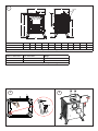
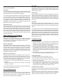
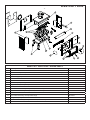
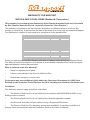
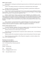
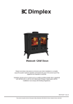
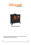
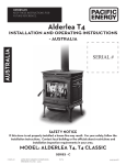
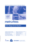
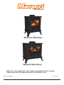
Westcott 1000 Stove
Westcott 2000 Stove
WESTCOTT 1000 & WESTCOTT 2000 STOVES HAVE BEEN TESTED TO SHOW
COMPLIANCE WITH THE EMISSION LIMITS OF AS/NZS4013:1999
PART NO.592006
2011-02-03
CONTENTS
DIMENSIONS
1
DIAGRAMMES
2
SAFETY ADVISE
3
ASSEMBLY
3
INSTALLATION
3
OPERATING INSTRUCTIONS
4
SAFETY NOTES
5
GENERAL MAINTENANCE
5
TROUBLE SHOOTING
5
AFTER SALES SERVICE
6
SPARE PARTS WESTCOTT 1000
7
SPARE PARTS WESTCOTT 2000
8
WARRANTY
9
WARRANTY REGISTRATION FORM
11
-1-
1
(
#
$
,$IA
*
'
!
"
+
&
%
Table 1 - Dimensions
A
B
C
D
E
F
G
H
J
K
L
Westcott 1000
580
540
416
208
434
105
55
336
120
425
128
Westcott 2000
602
554
544
272
564
102
55
309
126
418
154
Note: All Dimensions in mm. Dimensions stated may be subject to a slight ± variation.
Table 2 - Dimensions
Flue Outlet Size
Weight
Westcott 1000
125
73
Westcott 2000
150
88
Note: All Dimensions in mm. Dimensions stated may be subject to a slight ± variation.
2
3
!
X
- 2-
4
5
6
#
"
$
!
7
8
-3-
Wescott 1000 & 2000
IMPORTANT: THESE INSTRUCTIONS SHOULD BE READ CAREFULLY AND RETAINED FOR FUTURE REFERENCE
Important Safety Advice
Assembly of the stove
Please read these instructions carefully before installing
or using this appliance. Failure to do so may result in
damage to persons and property.
To make the product easier for handling on installation, remove
the baffle plate, side bricks, back brick and door. Place these in
a secure place to avoid damage. These must be refitted after
installation.
Installation of this appliance must be carried out by a
suitably qualified competent person in accordance with
all Building Regulations, including those referring to
Local Authority Bye-Laws, National Standards and Codes
of Practice.
Do not install this appliance on a shared flue.
This appliance operates at very high temperatures and
retains its heat for a period after use. Do not touch any
surfaces while in use. All persons including children and
the infirm should be warned of this and not allowed to
touch any surfaces while in use. Please use a suitable
fireguard to prevent contact when in use.
Do not place any photographs, paintings, TV’s or other
combustible items near the appliance as exposure to
hot surfaces will cause damage. Maintain safe distances
from combustibles in all cases in accordance with these
instructions – please refer to installation.
The operator must use the tools provided. The mitten
provided is a tool.
Ensure that there is adequate ventilation in the room in
accordance with building standards. Do not obstruct any
of the air inlets or outlets on the appliance.
A flue damper should not be fitted.
This appliance is for domestic heating use only in
accordance with these operating instructions. Do not
make any unauthorised changes to the appliance.
Only use recommended fuels. Do not burn petroleum coke
fuels, household waste or plastic in this appliance.
Use hardwood only with a moisture content of less than
25%. Burning soft or wet fuels such as unseasoned timber,
painted or treated timber will only result in a build up of
tar in the stove and the flue pipe and will cause staining
of the glass.
Do not use flammable liquids to ignite the fire.
Avoid the use of aerosols in the vicinity of the stove when
it is in operation.
Clean your flue pipe at once a year (Check your House
Fire Insurance) to ensure there are no blockages. Do not
allow a build up of ash to occur in the ash pan as this will
cause the grate to burn out prematurely.
Regular maintenance should be carried out by a
Competent Engineer.
The legs and other fixings are packed in the ashpan for safe
keeping in transport. Fix the legs to the underside of the product
using the bolts provided (Fig 2).
The stove is supplied ready for top flue connection. For Rear flue
connection remove the collar and blanking plates and fit in the
desired position. The collar can be fitted on the top or the rear of
the product. Seal with fire cement to ensure it is air tight (Fig 3).
The primary air sealing plate is located on the front of the grate.
To locate in position, slacken the screws beneath the grate and
pull forward, then close the door fully, open again and tighten the
screws (Fig 4).
Installation Instructions
General
These instructions give a guide for the installation of the stove but
in no way absolves the installer from responsibilities to conform
to all relevant standards relating to the installation of solid fuel
appliances.
In the interests of your safety, most building regulatory Authorities
in Australia and New Zealand require any wood fire installation to
comply with Installation Standard AS/NZS 2918. They may also
have local requirements in addition to those in the Standard. Check
with your local Building Authority before commencing installation
to find if you will require a Permit and whether there are extra
requirements. All our Wood fires have been tested to ensure
that they will meet the appropriate safety Standard requirements
if the instructions in this book are followed. As the safety and
emissions performance can be affected by altering the appliance,
no modifications are allowed without written permission from the
manufacturer.
We recommend that a qualified specialist installer should
be used.
Please note that to the best of our abilities these instructions are
correct at time of printing, however we cannot be held responsible
for any differences in legislation which may occur in the future.
An extractor fan must not be used in the same room as this
appliance.
NOTE: WHILE ALL MODELS HAVE BEEN TESTED TO
SHOW COMPLIANCE WITH THE EMISSION LIMITS OF AS/
NZS.4013:1999, ONLY SOME MODELS MAY BE INSTALLED IN
DISTRICTS HAVING LOWER ALLOWABLE EMISSION LIMITS.
PLEASE CHECK WITH YOUR BOROUGH OR SHIRE COUNCIL
BEFORE PURCHASING A HEATER OR INSTALLING A WATER
BOOSTER.
WARNING: APPLIANCES INSTALLED IN ACCORDANCE WITH
THIS STANDARD SHALL COMPLY WITH THE REQUIREMENTS
OF AS/NZS 4013 WHERE REQUIRED BY THE REGULATORY
AUTHORITY, I.E. THE APPLIANCE SHALL BE IDENTIFIABLE
BY A COMPLIANCE PLATE WITH THE MARKING ‘TESTED
TO AS/NZS 4013’. ANY MODIFICATION OF THE APPLIANCE
THAT HAS NOT BEEN APPROVED IN WRITNG BY THE
TESTING AUTHORITY IS CONSIDERED TO BE IN BREACH
OF THE APPROVAL GRANTED FOR COMPLIANCE WITH AS/
NZS 4013.
-4-
Floor Protection & Installation Clearances
Please refer to the specific ‘Installation Specifications’ for the stove
concerned supplied with the stove.
Flue Connection
You MUST use a flue system, which complies with the current
installation Standard AS/NZS 2918.
Full instructions are supplied with the flue kit, and these MUST be
followed closely, including the minimum flue exit height from the
top of the floor protector and the minimum exit height above the
roofline or roof ridge as detailed in the instructions.
Other Flue Systems
Flues and flue heat shields other than those listed on the Installation
Specification Sheets may be used, but if they have not been tested
with these heaters, their installation clearances will be those
specified in AS/NZS 2918:2001 for untested flue installations.
Unless otherwise specified, all heat sensitive wall material must
be kept at least 600mm away from any flue, which is not fitted
with a flue heat shield.
Always seal the flue to the flue socket of the firebox using firebox
cement or fiberglass rope.
Connect the flue pipe to the stove making sure that it fits snugly
into the base of the flue collar (Fig.5). Seal the collar and flue
connection with fire cement or with other suitable high temperature
sealant. Add flue sections as required; note that all flue sockets
must face upwards.
Avoid using bends greater than 45° to the vertical. All flue pipes
should be as close to vertical where possible. For rear flue
connection the length of the horizontal run of the flue pipe should
not exceed 150mm.
This product should not be installed on a shared flue.
Commissioning
Upon completion of installation, the stove and flue system should
be tested by a suitably qualified person to make sure it is safe for
normal use. A smoke draw test should be completed to check for
soundness of joints and seals and also that all smoke and fumes
are taken from the appliance up the chimney and emitted safely.
First warm the flue with a blowlamp or similar for about 10 minutes.
Place a lit smoke pellet on the centre of the grate with the air
controls open. Close the door – the smoke should be drawn up the
flue and be seen to exit from the flue terminal. Complete the test
with all windows and doors shut in the room where the appliance
is fitted. If a ceiling fan is present it must be operated on max for
the duration of the test. If there are any extraction fans in adjacent
rooms these too must be operated on maximum setting during the
test with the interconnecting doors open. If any spillage occurs,
recheck the suitability of the flue system making sure there is
adequate air supply to the room (as per Building Regulations).
Light the appliance and slowly increase the temperature to
operating levels. Open the main fire door when the appliance
reaches normal operating condition and carry out a spillage test
using a smoke match or pellet around the door opening. If any
spillage occurs, open all windows, allow the fire to go out and
recheck the flue system and ventilation.
Operating Instructions
Warning: The door and operating handles become hot when
the stove is in use. For your safety use the glove provided.
Initial Firing of Stove
We recommend that you have two to three small fires before you
operate your stove to maximum heat output. This is to allow the
paint to cure and the castings to relax and consolidate location.
We recommend this ‘running in’ procedure after long idle periods
to preserve the life of the stove. During this you may notice an
unpleasant smell. It is not toxic but for your own sake we would
suggest that during this period you leave all doors and windows
open.
Air Controls
Primary air is controlled via the sliding vents (A - Fig 6) in the
bottom of the door; this provides a conventional air draught to the
bed of the fire. (+) indicates more air, (-) indicates less air, (+) and
(-) are marked on the primary and secondary air controls.
Secondary air is controlled via the sliding vent (B - Fig 6) above
the door. It is this ‘Airwash’ that keeps a clean and uninterrupted
view of the fire, also aiding in good secondary combustion of fuel
and reducing emissions into the chimney and environment.
Lighting the Stove
Place fire lighters or paper and kindling on the grate. Light the
fire at base leaving all air controls open. Allow the fuel to reach
a steady glow and build the fire up gradually. Once you have a
good fire established across the grate bed, further fuel can be
added as required.
Running the Stove
When your fuel is well alight you can start to restrict the primary
air intake. If you are only burning wood the primary air control can
be fully closed. If you are burning solid fuel you will require more
primary air. Your stove is burning with maximum efficiency when
a bright fire is achieved using minimum air inlet.
The stove can be banked up for long periods. When burning solid
fuel empty the ash pan. Open air controls and let the fire burn
brightly for a short period. Refuel and close air controls; the exact
setting required will depend on the fuel used and the chimney draw
so some practice may be necessary. To revive the fire, open air
controls until the fire is burning brightly, de-ash if necessary and
refuel. Set air controls as required. The stove is not suitable for
overnight burning.
Notes on Wood Burning
Wood burns best on a bed of ash and it is therefore only necessary
to remove surplus ash from the grate occasionally. Burn only
dry, well seasoned wood, which should have been cut, split and
stacked for 12 months with free air movement around all sides
of the stack to enable it to dry out. Burning wet or unseasoned
wood will create tar deposits in the stove and chimney and will not
produce a satisfactory heat output. When loading wood, make sure
that the end grain of the wood in the stove is pointing away from
the glass otherwise the moisture and gases coming from the end
grain of the wood will dirty the glass.
Table 5 - Maximum log lengths
Westcott 1000
300mm (12”)
Westcott 2000
400mm (16”)
-5-
Petroleum coke fuels or household waste should not be
burned on this appliance.
De-Ashing
To de-ash the grate insert the notch on the riddle hand tool into the
peg on the side of the stove (D - Fig 6), then draw the tool forwards
and backwards with a slow positive action (Fig 7).
The ash pan should be emptied each time after operating the stove
so not to let build up of ash occur. Where possible, it is best to
wait until the stove and ash has cooled before removing the ash
pan. To remove, open the stove door by lifting the handle upward
(C - Fig 6 then using the riddle handle lift the ash pan out of the
fire (Fig 8). For efficient burning of your appliance, make sure the
grate is clear of burnt debris; e.g. nails, etc.
Shut down Periods
If shutting down the stove for long periods (e.g. for summer months)
make sure that all ash is removed from the stove and that the
chimney flue ways and baffle plate are brushed clean. When the
stove is cold a vacuum cleaner may be used to remove any residual
ash or soot. Close the door and leave all air inlets open fully. This
action will ensure air circulation through the appliance and will help
to avoid corrosion and condensation within the appliance during
this shut down period.
Safety Notes for Your Guidance
FIRES CAN BE DANGEROUS.
Always use a fire guard in the presence of children, the elderly
or the infirm. Inform all persons the dangers of high temperatures
during operation of the appliance including the stove pipe.
Use operating tools provided.
DO NOT OVER FIRE.
It is possible to fire the stove beyond its design capacity. This could
damage the stove, so watch for signs of over firing. If any part of
the stove starts to glow red, the stove is in an over fire situation
and the controls should be adjusted accordingly to reduce air
intake. Never leave the stove unattended for long periods without
adjusting the controls to a safe setting. Careful air supply control
should be exercised at all times.
Warning - Fume Emissions
Properly installed and operated, this appliance will not emit fumes.
Occasional fumes from de-ashing and refuelling may occur.
Persistent fume emission must not be tolerated. If fume emission
does persist, then the following immediate action must be taken:
1. Open doors and windows to ventilate the room.
2. Let the fire out, or eject and safely dispose of fuel from the
appliance.
3. When the stove has cooled, check for chimney flue blockage
and clean if required.
Do not attempt to relight the fire until the cause has been identified.
If necessary seek professional advice.
General Maintenance
Baffle Plate
This should be removed at least once a month to prevent any
build up of soot or ash, which could lead to blocked flue ways
and dangerous fume emission. If the baffle plate is removed the
flueway can be swept through the appliance.
Stove Body
The stove is finished with a heat resistant paint and this can be
cleaned with a soft brush. Do not clean while the stove is hot,
wait until it has cooled down. The finish can be renovated with a
suitable brand of paint.
Glass Panels
Clean the glass panels when cool with a proprietary glass cleaner.
Highly abrasive substances should be avoided as these can
scratch the glass and make subsequent cleaning more difficult. Wet
logs on heated glass, a badly aimed poker or heavy slamming of
the doors could crack the glass panels. The glass will not fracture
from heat.
Flue Pipes
Check your flue pipe each year before starting to use your stove
for the winter. Birds may have nested in the flue cowl. The flue
pipe must be swept at least once a year by a Qualified Chimney
Sweep.
To avoid a build up of soot on the baffle plate (the plate inside the
stove above the grate) it must be removed and cleaned periodically.
This plate locates the back and side firebricks so note its position
before removal. To remove, lift plate and remove one side brick;
this will allow the plate to drop and aid removal. To replace, position
baffle plate on back and side plate, lift plate and replace remaining
brick, making sure it has located in position. This must be done
when the stove is cold.
Troubleshooting
1. Poor heat output
a. Stove too small for room: Seek advice from a Qualified Heating
Engineer as to (kW) output required for the room size. As a
guideline the volume of the room in cubic feet divided by 500;
e.g. room 15’x15’x8’ would require 3.6kW approx.
b. Chimney and/or flue pipe restricted, room ventilation restricted:
On installation these should have been checked but regular
maintenance is necessary as conditions can change; e.g. soot
build up, birds nesting, masonry fall, dust build up or furniture
blocking vents.
c. Poor quality fuel: Only burn dry seasoned timber, soft woods
have a lower heat output than hard woods per hour.
2. Dirty Glass Panel
a. Generally caused by poor fuel quality, see (1c)
b. Use secondary air slide (Airwash) for glass panel
c. Fire burning too low, open air vents on stove to create hot fire;
this may ‘burn’ glass clean.
d. If glass requires cleaning use glass cleaner recommended by
your supplier; only use glass cleaner on cold glass. DO NOT
USE any abrasives or scrapers as these will scratch glass and
increase future tar build up making it harder to clean.
3. Unburnt Fuel in Firebox
Insufficient air reaching fuel. Open primary air slide, this will supply
combustion air to burn fuel fully (unless it has reached a ‘point of
no return’)
Check if the ash pan is full and empty if required. De-ash with the
riddler to make sure the grate is not blocked and check for jammed
clinker or nails when the fire is out and the stove has cooled.
-6-
4. Smoke and Fumes Entering Room
These are very dangerous and must NOT be tolerated. Open
window and allow fire to burn out. Seek expert advice immediately.
DO NOT USE stove until the problem is solved.
5. Fire inside the Flue Pipe
Identified by loud roaring sounds, dense smoke and sparks emitting
from top of flue. Shut down the air supply by closing air vents,
close stove door fully and call fire brigade immediately. Regular
flue cleaning will prevent flue fires. Seek advice from a Qualified
Chimney Sweep. Flues must be checked annually and more often
when bitumas coal and poor quality smokey fuels are used.
After Sales Service
Please see warranty details at rear of this manual.
Should you require after sales service or should you need to
purchase any spares, please contact the retailer from whom the
appliance was purchased. Please do not return a faulty product
to us in the first instance as this may result in loss or damage and
delay in providing you with a satisfactory service. Please retain
your receipt as proof of purchase.
-7-
WESTCOTT 1000
6
14
3
2
7
5
15
12
9
8
11
4
16
13
10
1
WESTCOTT 1000 STOVE - SPARE PARTS
Item
Description
Part No
1
Door
MF09015
2
Grate Accessory Pack (incl Grate Outer, Grate inner, Con Rod)
MF09016
3
Adjustable Grate Plate
MF09017
4
Front Bar (log bar)
MF09018
5
Air Wash Deflector Plate
MF09019
6
Baffle Plate
MF09020
7
Grate/Ashpan Operating Tool
MF09007
8
Legs Accessory Pack (x2 off)
MF09009
9
Primary Air Slide
MF09021
10
Air slide knob Accessory Pack (x1 steel, x1 black finish)
MF09011
11
Door Handle Accessory Pack (x1 steel, x1 black finish)
MF09010
12
Ash Pan
MF09022
13
Hinge Pins (x2 off)
MF09035
14
Heat Bricks Accessory Pack (x2 side bricks, x1 rear brick)
MF09023
15
Door Glass Accessory Pack (includes clips)
MF09024
16
Mitten
MF09036
WESTCOTT 2000
-8-
WESTCOTT 2000 STOVE - SPARE PARTS
Item
Description
Part No
1
Door
MF09025
2
Grate Accessory Pack (incl Grate Outer, Grate inner LH & RH, Connector, Con Rod)
MF09026
3
Adjustable Grate Plate
MF09027
4
Front Bar (log bar)
MF09028
5
Air Wash Deflector Plate
MF09029
6
Baffle Plate
MF09030
7
Grate/Ashpan Operating Tool
MF09007
8
Legs Accessory Pack (x2 off)
MF09009
9
Primary Air Slide
MF09031
10
Air slide knob Accessory Pack (x1 steel, x1 black finish)
MF09011
11
Door Handle Accessory Pack (x1 steel, x1 black finish)
MF09010
12
Ash Pan
MF09032
13
Door Glass Accessory Pack (includes clips)
MF09033
14
Hinge Pins (x2 off)
MF09035
15
Heat Bricks Accessory Pack (x2 side bricks, x1 rear brick)
MF09034
16
Mitten
MF09036
-9-
WARRANTY FOR MASPORT
WOOD & MULTI-FUEL FIRES (Radiant & Convection)
This warranty is provided in New Zealand by Glen Dimplex Australasia Ltd and in Australia
by Glen Dimplex Australia Pty Ltd. (together referred as “Glen Dimplex”)
This warranty is provided to the first domestic purchaser of a Masport wood or multi-fuel fire
(radiant or convection). It applies from the date of purchase from or through an authorized Masport
Fire Distributor in relation to each product or component for the period below.
TYPE OF PART
WOOD FIRE FIRE BOX, CAST IRON
WOOD FIRE FIRE BOX, STEEL
MULTI FUEL FIRE BOX, CAST IRON
MULTI FUEL FIRE BOX, STEEL
DOOR GLASS & SEAL
FIREBRICKS / BOARDS & RETAINERS
SECONDARY AIR TUBES
BAFFLE COMPONENTS
WATER BOOSTER
GLEN DIMPLEX FLUE SYSTEMS
FANS & ELECTRICAL COMPONENTS
WARRANTY (In Years)
PARTS
LABOUR
10
5
10
5
5
2.5
5
2.5
1
1
1
1
1
1
1
1
1
1
1
1
1
1
During the warranty period, Glen Dimplex will repair or replace (at its option) any Masport Wood
Fire which is found to be defective in materials or workmanship. Repairs will be carried out by an
approved Masport Heating Service Agent.
What is covered under this warranty?
•
Repair or replacement of parts
•
Labour costs relating to the Wood or Multi-fuel Fire
•
Reasonable transport or travel costs.
Consumers may have additional rights under the Consumer Guarantees Act 1993 (New
Zealand) or the Australian Trade Practices Act 1974 including the Australian Consumer Law.
Conditions
This warranty does not apply and will be void where:
•
The Wood or Multi-fuel Fire is not installed in accordance with AS/NZS2918/:2001 or any
building code or consent;
•
The Wood or Multi-fuel Fire is not installed by a qualified specialist installer;
•
Any electrical work has not been carried out by a Registered Electrician;
•
The Wood or Multi-fuel Fire has been moved and reinstalled, or has been modified in a
manner that is not consistent with the Installation Guide or the Owner's Manual;
- 10 -
What is not covered?
•
Wear and tear, including wear and tear through normal use on Multi-fuel fire grates and cast
iron fire box liners.
•
Labour costs relating exclusively to components not manufactured by Glen Dimplex.
•
Damage caused by incorrect use or the burning of treated or painted wood, driftwood or
other fuels which are not recommended;
•
Travel costs for a distance greater than 50 km from the nearest approved Masport Heating
Service Agent. (The location of the Wood Fire must be advised to Glen Dimplex or its sales agents
at the time of purchase or using warranty registration form)
•
Defects, malfunctions or failures caused by incorrect installation, poor installation, normal
wear and tear, misuse, neglect, accidental damage or failure to follow operating instructions in the
Owner's Manual (including fuel selection, product operation and maintenance instructions), repairs
or modifications by persons not authorised by Glen Dimplex, use of parts not supplied by Glen
Dimplex, or damage or other events which have occurred since the product left the control of Glen
Dimplex.
•
Direct, indirect or consequential losses or special damages of any kind (including costs of
collection and delivery) other than repair or replacement of products or components under this
warranty, where any goods are acquired or used for the purposes of a business;
How to obtain warranty service?
•
Completed Warranty registration form (previous page) needs to be mailed within 30 days of
installation to your Glen Dimplex Warranty Registration Department.
•
Warranty Claims must be made at place of purchase.
•
Reasonable proof of purchase date is required to make a warranty claim. You should keep
your purchase receipt.
•
Warranty repair will be completed according to normal work practices of the service agent.
•
Make the faulty part(s) available to Glen Dimplex for inspection so that the validity of the
claim can be established by them.
Distributed in Australia by:
GLEN DIMPLEX AUSTALIA PTY LTD
Unit 2, 205 Abbotts Road, Dandenong South
Victoria, 3175
Phone: 1 300 556 816
Fax
: 1 800 058 900
Email : [email protected]
Web
: www.glendimplex.com.au
- 11 -
GLEN DIMPLEX WARRANTY REGISTRATION
WOOD & MULTI-FUEL FIRES (RADIANT & CONVECTION)
Thank you for purchasing a Masport Fire. We ask you to complete the following information
and return to the Glen Dimplex Warranty Registration Department on following address:
New Zealand:
P O Box 58473, Botany, Manukau 2163, Auckland
Australia:
Unit 2, 205 Abbotts Road, Dandenong South, Victoria 3175
Mr / Mrs / Miss / Ms Name:
_______________________________________________
Cut Here
Address:
_______________________________________________________________
_____________________________________ Post Code:
Telephone:
_________________________
Email
______________________________________________________________
Model:
_________________________
Serial Number: ______________________
Retailer:
_________________________
Purchase Date: ______________________
Price:
_________________________
Installed By: _________________________
Fax: _______________________________
Date Installed: _______________________
We at Glen Dimplex strive to provide you with quality products and have continuous product
development program. To help achieve our objectives to our mutual benefit we would
welcome your feedback on the following questionnaire.
Question
Please tick appropriate remark
1. General presentation of Product
□ Excellent
□ Good
□ Ok
□ Needs to Improve
2. Styling and Looks
□ Excellent
□ Good
□ Ok
□ Needs to Improve
3. Packaging
□ Excellent
□ Good
□ Ok
□ Needs to Improve
4. Is documentation easy to follow?
□ Excellent
□ Good
□ Ok
□ Needs to Improve
5. Fixtures & Fittings (Loose parts)
□ In order
□ Items missing
6. Do you currently own Masport or Dimplex product?
□ Yes
□ Needs to Improve
□ No
Which? ______________
7. Why did you decide on Masport? (tick one or more options)□ Knew this brand □ Suggested by Friend
□ Dealer Recommended
□ Better Price□ Performance
□ Features
8. Other Comments: _________________________________________________________________
Privacy Act Notice: the owner named on the Warranty Registration consents and agrees that Glen Dimplex may retain and use the
information in this warranty card, including details about the owner for marketing and development purposes. The owner also agrees
that Glen Dimplex may also share purposes with [intended recipients of such information]. In accordance with the New Zealand Privacy
Act 1993 and the Australian Privacy Act 1988, the owner shall have the right to request the correction of, as well as inspect, all personal
information held by Glen Dimplex on that owner.
Cut Here
Please cut and mail this completed form within 30 days of installation to your
Glen Dimplex Warranty Registration Department at the above address