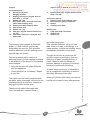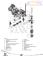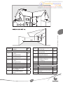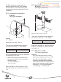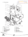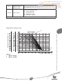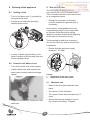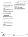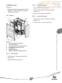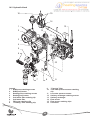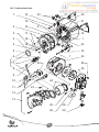
1
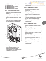
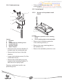
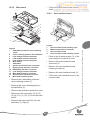
HIGH EFFICIENCY CONDENSING COMBINATION BOILER
Instructions for use
Installation and servicing
ISOTWIN CONDENS F 35 E
GUARANTEE REGISTRATION
Thank you for installing a new Saunier Duval appliance in your home.
Saunier Duval appliances are manufactured to the very highest standard so we are
pleased to offer our customers a Comprehensive Guarantee.
This product is guaranteed for 24 months from the date of installation or 30 months from
the date of manufacture, whichever is the shorter, for parts. In addition, this product is
guaranteed for 12 months from the date of installation or 18 months from the date of
manufacture, whichever is the shorter, for the labour.
The second year of the parts guarantee, from the beginning of the 13th month onwards
after installation or manufacture, is conditional upon the boiler having been serviced by a
CORGI registered gas installer,
in accordance with the manufacturer’s recommendations. We strongly recommend
regular servicing of your gas appliance, but where the condition is not met, any
chargeable spare parts or components issued within the applicable guarantee period still
benefit from a 12 month warranty from the date of issue by the manufacturer.
We recommend you complete and return as soon as possible your guarantee registration
card.
If your guarantee registration card is missing, you can obtain a copy or record your
registration by telephoning the Saunier Duval Customer Service number below.
For customer service call:
01773 525 914
Technical helpline: 01773 828400
For General and Sales enquiries:
Tel. 0870 6064351
To register your Saunier Duval appliance call:
0800 073 2144
Please complete the Benchmark Log Book at the end of this manual, if the appliance fails
to operate then the condition should be reported immediately to our service organisation
Saunier Duval Service 01773 525 914.
DO NOT REMOVE the appliance from the system until the engineer has confirmed and
signed the report allowing the return of the appliance to the merchant.
The merchant will NOT accept any returns unless supported by Saunier Duval Service
the engineer’s signed report.
Instructions for use
1
General points .........................................................................2
2
Documents .............................................................................2
3
Safety ......................................................................................2
3.1
3.2
Gas Leak or Fault ..............................................................................2
Safety regulations and recommendations ..........................................2
4
Guarantee / Responsibility ......................................................3
5
Appliance use..........................................................................4
6
Servicing .................................................................................4
7
Recycling.................................................................................4
8
Appliance use..........................................................................6
8.1
8.2
8.3
Control panel ......................................................................................6
Commissioning and lighting ...............................................................6
Temperature adjustment ....................................................................7
9
Turn the boiler off ....................................................................7
10
Fault finding.............................................................................7
11
Frost protection .......................................................................8
11.1 Boiler frost protection .........................................................................8
11.2 Installation frost protection .................................................................8
12
Maintenance/After Sales Service ............................................8
1
Instructions for Use
Index
1 General points
2 Documents
ISOTWIN CONDENS F 35 E boiler
is an appliance that uses condensing
technology, which recovers heat present
in waste gas.
Thanks to this operating principle,
the boiler consumes less energy and
decreases NOx and CO2 emissions.
• Please keep this manual as well as any
documents enclosed with it safe for
future reference.
We accept no liability in case of damage
due to the non-compliance of the
instructions of the present manual.
ISOTWIN CONDENS F 35 E boiler has a
double use (heating + instantaneous hot
water).
3 Safety
3.1
This appliance of the room-sealed type
is equipped with a flue exhaust and air
intake for combustion products called the
flue system. This flue system connection
principle offers the possibility to install the
appliance in any room and with no specific
ventilation requirements.
Gas Leak or Fault
• Do not switch on nor switch off the light.
• Do not activate the electrical switch.
• Do not use the phone in this risky area.
• Do not light up a flame (for example, a
lighter or a match).
The installation and the commissioning
of the appliance has to be carried out by
a skilled professional who is responsible
for the compliance of the installation and
the commissioning according to current
regulations.
• Do not smoke.
You also have to call on a skilled
professional for the maintenance and the
repairing of the appliance as well as for
any gas adjustment.
• Warn any person in the house.
• Turn off the gas emergency control
valve immediatly.
• Open all windows and doors to
ventilate the area.
• Inform the Gas Utility company or a
skilled professional.
3.2
Saunier Duval has specially designed
different accessories for your appliance
depending on your installation.
Safety regulations and
recommendations
Please observe the following safety
regulations and recommendations:
If you want to have a detailed list, please
contact your supplier or visit our website
www.saunier-duval.co.uk.
• Do not use any aerosols, solvents,
abrasive cleaner, detergents with
chlorine, paint, glue, etc. near the
appliance. Under unfavourable
conditions, these substances can be
very corrosive even for the flue.
2
Your appliance is guaranteed for a
period of 24 months from the date of
installation or 30 months from the date of
manufacture whichever is the shorter and
covers manufacturing defects only.
• Never switch off the safety devices and
do not try to handle these devices as
this could lead to a malfunction.
We, Saunier Duval, undertake to repair or
replace parts free of charge which
are recognised by us to be of faulty
manufacture - if necessary after return to
our factory for examination - on condition
that:
• Do not change:
- The appliance,
- The appliance environment,
- Water, air, gas and electric supply,
- Flue system.
• Never carry out by yourself
maintenance or repairing operations on
the appliance.
• The appliance was installed by a
qualifled gas installer in accordance
with installation instructions, and all the
relevant codes of practice, standards
and legislation in force.
• In case of a water leakage, immediately
close the cold water inlet of the
appliance and call a skilled professional
to repair the leakage.
• The appliance has been used for
normal domestic purposes and in
accordance with the manufacturer’s
operating and maintenance
instructions.
• Do not break sealed mechanisms.
• Do not modify the technical conditions
close to the appliance, as these are
very important as far as the appliance
safety is concerned.
For example: the minimum clearances
of the external sides.
• The appliance has not been serviced,
maintained, repaired dismantled or
tampered with during the guarantee
period, by anyone other than a
competent person.
Warning!
A heating safety valve with a discharge
pipe and a domestic hot water pressure
relief valve with a discharge pipe are fitted
to this appliance. The valves must not be
touched except by a skilled professional.
• The repair or replacement of parts
during the guarantee period does not
have the effect of extending the period.
This guarantee does not cover:
• If the valves discharges at any time, switch
•
Warning!
We advise you to be very careful when
adjusting hot water temperature: water
can be very hot when releasing from the
draw off tap.
• Any defects in the system to which the
appliance is connected.
the appliance off and isolate it from the
electrical supply.
3
Any defects or damage resulting
from incorrect or poor installation,
inadequate servicing, or maladjustment
of the gas or water used.
Instructions for Use
4 Guarantee / Responsibility
• Do not use or store any explosive
material or easily flammable (for
example, petrol, paint, etc.) in the room
where the appliance is situated.
6 Servicing
• Any deterioration or maladjustment
following changes in the nature or
pressure of the gas or the water used,
or a change in the characteristics of the
electrical supply voltage.
• Clean the case of the appliance with
wet soapy cloth.
• Do not use any abrasive cleaning
product as they could damage the
housing or plastic parts.
Notification of any fault should be made
to the appliance installer. No repairs
should be undertaken upon the appliance,
intending it to be covered by the product
guarantee without prior authorisation from
Saunier Duval.
7 Recycling
The appliance comprises many recyclable
parts. The packaging, the appliance and
the content of the package shall not be
thrown together with domestic waste
but eliminated according to the current
regulations.
IMPORTANT: The appliance serial number
must be quoted on all correspondence/
contact made with Saunier Duval.
This guarantee is in addition to your
statutory and other legal rights, which
will not be excluded or diminished by the
return of the guarantee registration card.
5 Appliance use
Saunier Duval’s appliances are
manufactured according to the latest
technical evolutions and current safety
regulations.
This appliance is used to produce
hot water using gas. Any other use
is considered as inappropriate and is
forbidden.
The manufacturer shall not be responsible
for any damage caused by another
use. In that case the user shall be the
responsible.
4
5
Instructions for Use
8 Appliance use
8.1
Control panel
1
5
2
6
3
4
7
Legend
1
Operating indicator
2
Display of the available pressure in the
heating circuit
3
Operating mode selection
4
DHW temperature adjustment
8.2
5
6
7
Commissioning and lighting
Display of the measured temperature in
the heating circuit
On/off switch
Heating temperature adjustment
• Push “MODE” to modify the operating
mode of the boiler. The ◄ symbol is
then situated in front of the selected
mode:
• Make sure that:
- the boiler is connected to the electrical
supply.
Central heating and
domestic hot water
- the gas service cock is open.
• Push the switch (6) until the “I” symbol
appears.
The operating indicator on the control
panel turns on: the boiler is ready to
run.
Central heating only
Domestic hot water only
Appliance frost protection
6
9 Turn the boiler off
Temperature adjustment
• Push the switch (6) until the “O” symbol
appears.
The appliance is no longer supplied
with electric power.
8.3.1 Domestic hot water temperature
adjustment
The domestic hot water must be set at
max 63°C.
• Push + or – on the
side to adjust the
max temperature.
The ECO symbol remains until 49°C.
We advise you to turn off the appliance
gas supply if you leave home for a long
period.
8.3.2 Heating temperature adjustment
10 Fault finding
• Push + or – on the
side to change
water temperature between 22°C and
the maximum value allowed by your
installer.
If there is a fault, then a fault symbol
displays and the operating indicator on the
control panel flashes red.
Warning !
Never try to service or repair the appliance
by yourself and only start the appliance
once a skilled professional repaired the
fault.
Observation:
/
side
A quick push on +/- or
displays the temperature value previously
selected
Symbol and
fault code
Cause
Corrective action
The operating
indicator is OFF.
Power failure
Check the mains power supply is on and that
the appliance is switched on at the spur or
socket. The appliance starts automatically
once the power supply is on. If the fault
persists, please contact a skilled professional.
Ignition fault
Air flow failure
Deactivate the boiler
Wait 5 seconds and then start the boiler again.
If the fault continues, please contact a skilled
professional.
Overheating fault
Please contact a skilled professionnal
Insufficient water
pressure in the system
Open the blue tap situated under the boiler
until you obtain a pressure between 1 and
2 bars on the indicator. If you have to fill it
this might be caused by a leakage in your
appliance. In this case, contact a skilled
professional to check the boiler and system.
Other defects
Please contact a skilled professionnal
code F1, F4
code F2, F3
code F5
7
Instructions for Use
8.3
11 Frost protection
12 Maintenance/After Sales Service
11.1 Boiler frost protection
Please note that an incorrect servicing can
affect the safety of the appliance and can
lead to injury.
In case of frost risk, do as follows:
• Make sure the boiler is supplied with
electrical power and gas.
To ensure the continued efficient and
safe operation of the appliance it is
recommended that it is checked and
serviced as necessary at regular intervals.
The frequency of servicing will depend
upon the particular installation conditions
and usage, refer to guarantee registration.
• Select the
operating mode on the
control panel.
The frost protection system operates the
boiler as soon as the temperature in the
heating circuit is under 4°C. The boiler
stops as soon as the water temperature in
the heating circuit reaches 16°C.
If this appliance is installed in a rented
property there is a duty of care imposed
on the owner of the property by the current
issue of the Gas Safety (Installation and
Use) Regulations, Section 35. Servicing/
maintenance should be carried out by
a competent person in accordance with
the rules in force in the countries of
destination. To obtain service, please call
your installer or Saunier Duval service.
11.2 Installation frost protection
• If you leave home for a few days, select
the minimum heating temperature on
the control panel of the boiler and just
decrease the setpoint temperature on
your room thermostat.
• If you leave home for a long period, see
chapter “Draining of the appliance” in
the installation manual.
8
Installation and servicing
1
Comments on the instructions............................................... 11
2
Appliance description ............................................................ 11
2.1
2.2
2.3
Data label ......................................................................................... 11
Mandatory WARNING for EEC countries ......................................... 11
Block diagram ..................................................................................12
3
Appliance location .................................................................13
4
Safety instructions and regulations .......................................14
4.1
4.2
Safety instructions ............................................................................14
Regulations ......................................................................................15
5
Appliance installation ............................................................16
5.1
5.2
5.3
5.4
5.5
5.6
5.7
5.8
5.9
Recommendations before mounting ................................................16
Dimensions ......................................................................................18
List of delivered equipment ..............................................................18
Fixing to the wall ..............................................................................18
Gas and water connection ...............................................................20
Connection to the condensate trap ..................................................24
Flue connection ................................................................................24
Electrical connection ........................................................................27
Wiring diagram .................................................................................28
6
Commissioning......................................................................30
7
Specific adjustments .............................................................30
7.1
7.2
Heating circuit adjustment ................................................................30
Access to the boilers technical data
(for professional and After Sales Service use only) .........................32
8
Draining of the appliance ......................................................34
8.1
8.2
Heating circuit ..................................................................................34
Domestic Hot Water circuit ...............................................................34
9
Installation and servicing instructions strictly reserved for qualified gas installers
Index
9
Gas conversion .....................................................................34
9.1
9.2
9.3
Maximum rate ..................................................................................34
Minimum rate ...................................................................................35
Reactivation .....................................................................................35
10
Fault finding...........................................................................36
11
Control / Commissioning .......................................................38
12
User information ....................................................................38
13
Spare parts............................................................................38
14
Maintenance..........................................................................39
14.1
14.2
14.3
14.4
14.5
Casing ..............................................................................................39
Hydraulic block .................................................................................40
Heating Return Filter ........................................................................41
Condensate trap ..............................................................................41
Combustion block ............................................................................42
15
Remplacement of parts .........................................................44
15.1
15.2
15.3
15.4
15.5
Hydraulic block .................................................................................46
Combustion block ............................................................................48
DHW storage vessel / Expansion vessel .........................................50
Condensate trap ..............................................................................52
Control panel ....................................................................................52
16
Technical data .......................................................................54
10
1 Comments on the instructions
Member States relating to appliances
burning gaseous fuels.
• Please give all of the instructions to
the user. The user shall keep them for
future reference.
We accept no liability in case of damage
due to the non-compliance of the
instruction manual.
- Directive 73/23/EEC on the
harmonisation of the Laws of the
Member States relating to electrical
equipment designed for use within
certain voltage limits.
2 Appliance description
2.1
Data label
The data label certifies the origin where
the product was manufactured and the
country for which it is intended.
Warning! The appliance shall only be used
with the gas types indicated on the data
label.
• Clear the route before attempting the
lift.
2.2
• Ensure safe lifting techniques are used
- keep back straight - bend using legs.
Mandatory WARNING for EEC
countries
• Keep load as close to body as possible.
This appliance is designed, approved and
inspected to meet the requirements of the
intended market. The data label indicates
where the product was manufactured and
the country for which it is intended.
• Do not twist - reposition feet instead.
• If two persons performing lift, ensure
co-ordinated movements during lift.
• Always use assistance if required.
Manufacturer’s instructions must not be
taken as overriding statutory requirements.
Reference in these instructions to British
standards and statutory regulations/
requirements apply only to the United
Kingdom. For Ireland the current edition of
I.S.813 «Domestic Gas Installations» must
be used.
This appliance meets the requirements
of Statutory Instrument, No. 3083 The
Appliance (Efficiency) Regulations,
and therefore is deemed to meet the
requirements of Directive 92/42/EEC
on the efficiency requirements for new
hot water appliances fired with liquid or
gaseous fuels.
This appliance certificated to the
current issue of EN 483: 2000 for
performance and safety. It is important
that no alteration is made to the appliance,
without permission, in writing, from
Saunier Duval. Any alteration that is
not approved by Saunier Duval could
invalidate the warranty and could also
infringe the current issue of the Statutory
Requirements.
Type test for purposes of Regulation 5
certified by: Notified body 0063. Product/
production certified by: Notified body
0086.
The CE mark on this appliance shows
compliance with:
- Directive 90/396/EEC on the
approximation of the laws of the
11
Installation and servicing instructions strictly reserved for qualified gas installers
- Directive 89/336/EEC on the
approximation of the Laws of
the Member States relating to
electromagnetic compatibility.
IMPORTANT. With regards to the
Manual Handling Operations, 1992
Regulations, the following lift operations
are recommended as the appliance weight
exceeds a one-man lift.
2.3
Block diagram
D1
D2
12
26
27
28
29
30
31
32
33
34
35
36
37
38
A
B
C
D
D1
D2
E
F
3 Appliance location
Filter on cold water inlet
Filling system
Filter on heating circuit
Heating isolating valve
Domestic cold water isolating valve
Heating isolating valve
Gas isolating valve
DHW pump
Storage anode protection
Non return valve
Temperature / pressure relief valve
Tapping (plug connection) for the
recirculation loop
Pressure reducing valve and check
valve
Heating return
Cold water inlet
Heating flow
Domestic hot water outlet
Discharge from HTG safety valves
Discharge from temp / press and
expansion valve (to tundish)
Gas
Cold water supply
• Make sure you keep an appropriate
distance between the sides of the
appliance to ensure total accessibility
for servicing.
• This appliance is not suitable for
outdoor installation.
• The appliance must be mounted on a
flat wall, which is sufficiently robust to
take its weight.
• This appliance may be installed in any
room, although particular attention is
drawn to the installation of an appliance
in a room containing a bath or shower
where reference must be made to the
relevant requirements. In GB this is the
current I.E.E. WIRING REGULATIONS
and BUILDING REGULATIONS.
• The appliance is room sealed, so when
it is installed in a room or space, a
permanent air vent is not required.
• Do not install the appliance above
another appliance that could damage
it (for example, above a cooker that
might emit steam or grease) or in a
room, which has a lot of dust in the
atmosphere which is corrosive.
• In IE reference should be made to the
current edition of I.S.813 «Domestic
Gas Installations» and the current ETCI
rules.
13
Installation and servicing instructions strictly reserved for qualified gas installers
Legend
1
Flue outlet
2
Main heat exchanger
3
Burner
4
Ignition and control electrode
5
Fan
6
Gas control valve
7
DHW storage vessel
8
Condensate drain
9
Overheat safety thermostat
10 Temperature sensor for DHW storage
vessel
11 Expansion vessel
12 Heating return thermistor
13 Heating flow thermistor
14 Ignition module
15 Heating Pump
16 Water pressure sensor
17 Domestic plate to plate heat exchanger
18 Three way valve
19 Domestic expansion vessel
20 Drain cock
21 Flow switch
22 Heating discharge safety valve
23 DHW temperature sensor
24 DHW discharge safety valve
25 Heating isolating valve
4 Safety instructions and
regulations
Warning! This appliance must be
earthed. This appliance must be wired in
accordance with these instructions. Any
fault arising from incorrect wiring cannot
be put right under the terms of the Saunier
Duval guarantee.
This appliance is tested and certificated
for safety and performance. It is, therefore,
important that no alteration is made to the
appliance, without permission, in writing,
from Saunier Duval.
Any alteration not approved by Saunier
Duval, could invalidate the certification,
appliance warranty and may also
infringe the current issue of the statutory
requirements.
4.1
The following safety instructions must
be imperatively followed during the
maintenance and the replacement of
spare parts.
• Stop the appliance (see chapter “Turn
the boiler off” of the Instructions for
use).
Safety instructions
If the gas pressure at the inlet of the
appliance is outside the range specified,
you shall not start the appliance. If the
cause of the problem cannot be found
nor solved, please contact the Gas Utility
company.
• Disconnect the appliance from the
mains power supply with the socket or
the double-pole switch (with a minimum
gap of 3mm for both poles).
• Turn off the gas control valve.
• Close the shut off valves located on the
connection sockets.
Warning! Incorrect installation can cause
electric shock or appliance damage.
• Drain the appliance if you want to
change hydraulic parts of the appliance.
- When making the connections, locate
the sealing washers properly so as to
avoid any gas or water leakage.
• Let the appliance cool down before
undertaking any maintenance work.
- Never use a wire brush or stiff-bristle
scrubbing brush to clean the heat
exchanger as this could damage the
appliance.
• Protect all the electrical components
from water when you carry out any
work.
- Under no circumstances must the User
interfere with or adjust sealed parts.
Under Section 6 of The Health and
Safety at Work Act 1974, we are required
to provide information on substances
hazardous to health.
The adhesives and sealants used in this
appliance are cured and give no known
hazard in this state.
• Use only new O-rings and gaskets.
• After having completed work on gas
components, check their tightness.
• When the replacement work is
completed, perform an operation test of
the replaced parts and the appliance.
In the event of the appliance overheating
the safety devices will cause a safety
shutdown. If this happens, call your
installation/servicing company.
14
Regulations
In IE: I.S.813, BS5546, BS 5449, BS
7074, BS 7593.
When installing and commissioning the
appliance, the regulations below shall be
observed in their current version:
Where no British Standard exists,
materials and equipment should be fit
for their purpose and of suitable quality
and workmanship. The installation of
this appliance must be carried out by
a competent person in accordance
the rules in force in the countries of
destination. Manufacturer’s instructions
must not be taken as overriding statutory
requirements.
In your own interests and that of safety, it
is the Law that ALL gas appliances must
be installed by a competent person only,
in accordance with the current issue of the
above regulations.
In GB the installation of the appliance
must be carried out by a competent
person as described in the following
regulations:
If the appliance is to be installed in a
timber frame building it should be fitted
in accordance with the Institute of Gas
Engineers document IGE/UP/7/1998. If
in doubt seek advice from the local gas
undertaking or Saunier Duval.
- The manufacturer’s instructions
supplied.
- The Gas Safety (Installation and Use)
Regulations.
- The appropriate Buildings Regulations
either The Building Regulations, The
Building Regulations (Scotland), The
Building Regulations (Northern Ireland).
The installation is subject to building
regulation approval, notify the Local
Authority of intention to install.
- The Water Fittings Regulations or
Water byelaws in Scotland.
- The Health and Safety at Work Act,
Control of Substances Hazardous to
Health (COSHH).
- The Current I.E.E. Wiring Regulations.
Where no specific instructions are given,
reference should be made to the relevant
British Standard Code of Practice.
In IE, the installation must be carried out
by a competent person and installed in
accordance with the current edition of
I.S.813 «Domestic Gas Installations»,
the current Building Regulations and
reference should be made to the current
ETCI rules for Electrical Installation.
In GB the following Codes of Practice
apply: BS4814, BS6798, BS5440 Part 1
and 2, BS5546 Part 1, BS5449, BS6891,
BS6700, BS7074 Part 1 and 2, BS7593,
BS7671.
15
Installation and servicing instructions strictly reserved for qualified gas installers
4.2
5 Appliance installation
chapter “Technical Data” at the end of this
instruction manual.
All the dimensions in this chapter are
expressed in mm.
5.1
The piping route should be designed in
such a way that it avoids any air locks
and make purging of gas from the system
easier. Bleeders should be placed at each
high point of the system as well as on any
radiators.
Recommendations before
mounting
5.1.1 Domestic hot water circuit design
The circuit should be designed to avoid
any unnecessary flow losses (decrease
the number of elbows).
Total water volume accepted by the
heating circuit depends, amongst
other things, on the cold static load.
The expansion tank fitted in the boiler
is delivered factory set (see chapter
“Technical Data” at the end of this
instruction manual). At commissioning, it
is possible to change this pressure in case
of a larger static load. We advise you to
provide a drain valve at the lowest point of
the system.
The boiler will operate with a minimum
supply pressure but with a low flow.
Optimum performance will be achieved
with a pressure of 1 bar.
5.1.2 Heating circuit design
ISOTWIN CONDENS boilers can be used
for any kind of installation: serial or
derivated double tube, single tube, hot
floor, etc...
Heating surfaces can be made up with
heaters, convectors or unit heaters.
If thermostatic radiator valves are used,
we advised you not to fit in a room where
a room thermostat is fitted.
• In case of an old installation, flush the
heating system before installing the
new boiler.
Warning: If the materials used are of
a different type, some corrosion can
occur. In that case, we advise you to
add an inhibitor to the heating circuit
water (according to the manufacturer’s
recommendations) that could avoid gas
production and oxide formation.
• If the boiler is not immediately installed,
protect all the pipe fittings so as to
avoid that any plaster or paint that
could impede the connection.
The pipework sections should be fixed by
using the following flow/pressure curve
(see chapter “Heating circuit adjustment”).
The system will be calculated according
to the flow corresponding to the power
that is really required without taking into
account the maximum power that the
boiler can supply. Nevertheless, we advise
you to have a flow big enough so that the
temperature difference between outgoing
and return is under or equal to 20°C. The
minimum flow rate is indicated in the
16
5.1.3 Tundish discharge
clear visibility at one or these of these
locations. Examples of acceptance
discharge arrangements are:
The internal safety valves, 24 and 36 have
been tee’d together and the discharge
pipe run so that it exits at the right hand
bottom of the boiler (see chapter «Block
diagram»). The tundish (supplied) must
be used with this outlet within the normal
guidelines and code of practice and must
be installed so that it is visible to the
occupants and positioned away from any
electrical devices.
- Ideally below a fixed grating and above
the waterseal in a trapped gully.
It is necessary, during installation,
to connect a 22 mm diameter metal
discharge pipe to a suitable position
outside the building. It is permissible to
use copper pipe.
- Discharges at high level; e.g into metal
hopper and metal down pipe with
the end of the discharge pipe clearly
visible (tundish visible or not) or into
a roof capable of withstanding high
temperature discharges of water and
3m from any plastics guttering systems
that would collect such discharges
(tundish visible).
Warning! The discharge pipe from the
tundish should terminate in a safe place
where there is no risk to persons in the
vicinity of the discharge, be of metal and:
• Be at least one pipe size larger than
the nominal outlet size of the safety
device unless its total equivalent
hydraulic resistance exceeds that of
a straight pipe 9m long i.e. discharge
pipes between 9m and 18m equivalent
resistance length should be at least
larger than the nominal outlet size of
the safety device, between 18m and
27m at least 3 sizes larger, and so on.
Bends must be taken in to account in
calculating the flow resistance.
• Be positioned away from any electrical
appliances.
- Where a single pipe serves a number
of discharges, such as in blocks of
flats, the number served should be
limited to not more than 6 systems
so that any installation can be
traced reasonably easily. The single
common discharge pipe should be
least one pipe size larger then the
largest individual discharge pipe to
be connected. If unvented hot water
storage systems are installed where
discharges from safety devices may not
be apparent i.e. in dwellings occupied
by blind, infirm or disabled people,
consideration should be given to the
installation of an electronically operated
device to warn when discharge takes
place.
• Have discharges visible at both the
tundish and the final point of discharge
but where this is not possible or
practically difficult there should be
Note: the discharge will consist of scalding
water and steam. Asphalt, roofing felt
and non-metallic rainwater goods may be
damaged by such discharges.
• Have a vertical section of pipe at least
300mm long, below the tundish before
any elbows or bends in the pipework.
• Be installed with a continuous fall.
17
Installation and servicing instructions strictly reserved for qualified gas installers
- Downward discharges at a low level;
i.e. up to 100mm above external
surfaces such as car parks, hard
standing, grassed areas etc. are
acceptable providing that where
children may play or otherwise come in
to contact with discharges, a wire cage
or similar guard is positioned to prevent
contact, whilst maintaining visibility.
5.2
5.1.4 Water treatment
In the case of an existing installation, it is
Essential that prior to installing the new
boiler the system is thoroughly flushed.
For optimum performance after
installation of a new system, the boiler and
its associated central heating system
should also be flushed.
Flushing should be carried out in
accordance with BS7593: 1992 using a
cleanser such as Sentinel X300 or X400,
Fernox Superfloc or Salamander corrosion
guard cleaner.
Dimensions
301
890
For long-term corrosion protection, after
flushing, an inhibitor suitable for stainless
steel heat exchangers should be used,
refer to the current issue of BS 5449 and
BS 7593 on the use of inhibitors in central
heating systems. Examples are Sentinel
X100 Fernox or Salamander corrosion
guard inhibitor.
480
700
5.3
List of delivered equipment
The boiler is delivered in two packages:
- The boiler and the hanging bracket.
- One documentation pack:
- 1 user and installation manual
- 1 guarantee envelope
- 1 Wiring diagram
- 1 gasket pack
One parts pack:
- 1 connection pack 1
- 1 connection pack 2 + wall template
- 1 safety valves drain pack
The flue is supplied separately and will
depend upon the configuration of the
installation.
5.4
Fixing to the wall
• Make sure the material you use fits
those of the appliance.
• Chose the location of the appliance.
See chapter “Appliance location”.
18
• Remove front panel, unscrew and
remove the two retaining screws from
the bottom of the front panel. Remove
front panel by lifting up and forward.
n.
mi
kg
5
1
n.
mi
kg
15
• To remove the self adhesive wiring
diagram label from the document
envelope, fit the self adhesive wiring
diagram label to the inside of the front
panel, put front panel in a safe place to
avoid damaging it.
15
• The hanging bracket will be adapted to
the features of the bearing wall and will
have to take into account the weight of
the boiler filled with water.
165
85
n.
mi
kg
n.
5
mi in.
1
kg
m
5
1
kg
15
• Slowly lower the boiler.
• Set the seals on the different pipe
fittings.
• Make connections to boiler, gas,
water and heating cocks with the tube
assemblies supplied in piping pack.
45
• Do not forget to connect
the filling loop extension
on the filling tap.
Ø105
104.5
50
min.
• Screws mechanical features will match,
at least, the values indicated on the
following sketch.
19
Installation and servicing instructions strictly reserved for qualified gas installers
250
n.
mi
• Place the boiler above the hanging
bracket.
• Drill the holes for the fixing screws
in accordance to the diagram below
and to the size of the wall template
delivered with the appliance.
45
kg
5.5
Gas and water connection
• Before undertaking any operation,
carefully clean the pipes with an
appropriate product in order to remove
impurities such as filings, welds,
different oils and greases that may
be present. These foreign bodies
may enter the boiler and disrupt the
operation.
• Do not use any solvents that could
damage the heating circuit.
• Take care when soldering pipes as the
heat could damage the seals and cause
leakage. Fit washers after joints have
cooled.
1
2
3
4
18
5
17
6
16
7
15
8
230
256
9
10
11
5
5
12
8
A
3
13
20
14
6
6
angular bush to weld Ø 15 + nut 1/2"
Legend
Connection pack 1 :
A
Pressure test point
1
Hanging bracket
2
Heating return pipe: angular bush to
weld Ø 22 + nut 3/4"
5
Gasket 3/4" (x3)
8
Cold water inlet + domestic hot water
outlet with isolating valve
12 Heating flow with isolating valve
13 Gas service cock
14 Gasket 1/2" (x3)
15 Gas pipe: angular bush to weld Ø 15 +
nut 1/2"
16 Cold water inlet pipe + domestic hot
water pipe:
17
Heating flow pipe: angular bush to weld
Ø 22 + nut 3/4"
Connection pack 2 :
4
Heating return with isolating valve
9
Nut / Pressure gauge connection
10 Gasket
11 Heating return filter
the boiler fittings pack.
This must be extended, using not less
than 15mm o.d. pipe, to discharge, in a
visible position, outside the building, facing
downwards, preferably over a drain.
The heating return adapter is fitted with
a filter (11) that could be reached by
unscrewing the end nut. This operation
must be achieved once the heating return
shut-off taps are closed.
The pipe must have a continuous fall
and be routed to a position so that any
discharge of water, possibly boiling, or
steam cannot create any danger to
persons, damage to property or external
electrical components and wiring.
The test pressure will be read on a
pressure gauge (9) (not supplied) screwed
in the position of the first nut of the heating
return adapter.
• Only use the genuine seals delivered
with the appliance.
To ease future servicing it is advisable to
use a compression type fitting to extend
the safety discharge valve tube.
• Check that there is no leakage. Repair
if need be.
Warning! Cylinder relief valve connections
should not be used for any other purpose.
The pipes from the heating and domestic
hot water safety discharge valves must not
discharge above an entrance, window or
any type of public access area.
Take the short safety discharge tube,
union nut and seal, supplied loose in
21
Installation and servicing instructions strictly reserved for qualified gas installers
Gasket pack :
Cold water flow rate limiter
3
6
Gasket (x2)
7
Gasket (x3)
23
1
22
2
21
3
20
24
4
19
18
17
16
15
14
5
6
7
8
9
9
7
10
8
13
12
11
Legend
1
Domestic hot water safety valve
2
Drain cock
3
Filling loop extension knob
4
Gasket
5
Nut
6
Discharge valve for PRV (BLUE) on
domestic hot water circuit
7
Nut (x2)
8
Gasket (x2)
9
Gasket (x2)
10 Union coupling
11 Nut
12 Biconical ring
13
14
15
16
17
18
19
20
21
22
23
24
22
Tundish
Biconical ring
Nut
Nozzle
Nut
Inner tee
Biconical ring coupling
Biconical ring
Discharge pipe for PRV (RED) on
heating circuit
Gasket
Nozzle
Tube for drain valve
Valve outlet size
Minimum size
of discharge
to tundish D1
Minimum size of
discharge pipe
D2 from tundish
G 1/2”
15 mm
22 mm
28 mm
35 mm
G 3/4”
22 mm
28 mm
35 mm
42 mm
G 1”
28 mm
35 mm
42 mm
54 mm
1
500 mm
Maximum resistance
allowed expressed as
a length of straight pipe
i.e. no elbows or bends
0.8 m
1.0 m
1.4 m
up to 9 m
1.0 m
1.4 m
1.7 m
up to 18 m
up to 27 m
D1
Resistance
created by
each elbow
or bend
1.4 m
1.7 m
2.3 m
D2
300 mm max.
1
2
Legend
1
Tundish (supplied)
2
Gully
D1 Discharge pipe
D2 Discharge pipe
4
3
Discharge pipe D1: from heating safety
valve on jig.
Discharge pipe D2: from domestic hot
water safety valve.
Legend
1
Safety device eg. temperature relief
valve
2
Tundish (supplied)
3
Trapped gully
4
Fixed grating
Discharge pipe D1: from temperature relief
valve to tundish.
Discharge pipe D2: from tundish with
continuous fall.
• See table above for size examples.
23
2
Installation and servicing instructions strictly reserved for qualified gas installers
max.
5.6
Connection to the condensate
trap
3
1
OK
2
OK
Legend
1
Acces plugs for cleaning purposes
2
Condensate drain connection
3
Condensate trap
• Connect the flexible pipe to a discharge
system leading to the sewer in
compliance with the instructions below:
5.7
Flue connection
Different flue outlet configurations can be
carried out.
• Use the condensate drain flexible
connection pipe supplied (2).
• Consult your supplier for more
information about the other possibilities
and associated accessories.
• Ensure there is a conbinual fall of 2.5°
(44 mm/m).
• Do not let the condensate drain flexible
connection fall into the trap.
Warning! You can only use flue
accessories approved for the ISOTWIN
CONDENS.
• Do not use copper pipes.
Important notice:
The float of the condensate trap also
ensures fume tightness. Therefore, it
is not necessary to add water in the
condensate trap.
Saunier Duval’s horizontal flue
automatically provides a 3° angle that
enables the return of the condensates to
the appliance.
• Whatever the kind of flue system
chosen, observe the minimum
distances indicated in the chart below
to position the flue terminals.
24
Position of the flue
terminal
Horizontal flues
directly below an opening,
air brick,
A
opening windows
above an opening, air brick,
B
opening windows
horizontally to an opening,
air brick,
C
opening windows
D
below gutter, drain/soil pipe
E
below eaves
F
below a balcony or car port
from vertical drain pipes
G
and soil pipes
from internal/external
H
corners
Position
to a boundary alongside
the terminal
above adjacent ground or
I
balcony level
from surface or a boundary
J
facing the terminal
K
facing terminals
from opening (door/
window) in car port
L
into dwelling
M
vertical from a terminal
N
horizontally from a terminal
Vertical flues
P
from another terminal
Q
above roof level
from adjacent opening
R
window
S
from adjacent wall to flue
mm
H*
300
300
300
25
25
25
25
25
25
300
300
600
1200
1200
1500
300
600
300
1000
300
Installation and servicing instructions strictly reserved for qualified gas installers
S
R
5.7.2 Vertical concentric flue
Ø 60/100
(C33 type installation)
H*: This dimension comply with the
building regulations, but it may need to
be increased to avoid wall staining and
nusance from pluming depending on site
conditions.
5.7.1 Horizontal concentric flue
Ø 60/100
(C13 type installation)
L
L
1
72
Maximum flue index: 150 Pa
This value is reached with the length of
the maximum duct (L) + 1 90° elbow.
Legend
1
Gasket
Flue model
Ø 60/100
Maximum flue index: 150 Pa
Every time an extra 90° elbow is used (or
2 off 45°), the length (L) should be reduced at by 1 m.
This value is reached with the length of
the maximum duct (L) + 1 90° elbow.
Flue model
Ø 60/100
Max. length
5.5 m
Max. length
5m
5.7.3 Twin flue 2 x Ø 80
(C53 type installation)
Warning!
A Plume mangement kit can be installed at
the extremity of the duct.
- Any duct that goes through a wall
and whose temperature is over 60°C
from the room temperature will be
thermally insulated at this passage.
The insulation will be composed of an
appropriate insulating material whose
thickness is ≥ 10 mm and thermal
conductibility λ ≤ 0.04 W/m.K.
• Refer to the instructions sheet of the
accessory and take it into account the
following length:
- L1 ≤ 6 m whatever L
- L2 = L = 5 m
Every time a 90° elbow is used (or 2 off
45°), the length (L) should be reduced by
1 m.
26
LL11
The mains cable integrated in the boiler is
specific: if you want to change it, order it
exclusively from Saunier Duval service.
L2
188
Maximum flue index: 150 Pa
This value is reached with 2 elbows, the
separator and the maximum duct length
(L1+L2) of 40 m.
5.8
Installation and servicing instructions strictly reserved for qualified gas installers
Every time an extra 90° elbow is used (or
2 off 45°), the length (L) should be reduced by 1 m.
Electrical connection
Warning! Incorrect installation can cause
electric shock or appliance damage.
• Connect the power cable of the boiler to
the 230 V single-phase + earth network.
• Observe the live and neutral connection
on the boiler.
Important: A skilled professional should
achieve the electric connection of the
appliance. All the interventions achieved
inside the appliance will be made by
the After Sales Service or a skilled
professional.
Isolation should be by a double pole
switched fused spur box, with a minimum
gap of 3mm for both poles.
The fuse of the PCB must be connected to
the neutral.
27
5.9
Wiring diagram
1
2
3
4
5
6
18
7
17
16
8
9
10
11
13
12
Legend
1
Overheat thermostat
2
Fan
3
Gas valve
4
Heating return thermistor
5
Heating flow thermistor
6
Water pressure sensor
7
Water flow sensor
8
DHW pump
9
Heating pump
10
11
12
13
14
15
16
17
18
28
14
15
Main board
User interface
Main reset switch
Chassis earth
Fuse
Three way valve
Ignition module
DHW temperature sensor
Ignition and controle electrode
29
Installation and servicing instructions strictly reserved for qualified gas installers
6 Commissioning
7 Specific adjustments
• Slide the switch until the “I” symbol
appears.
The operating indicator on the control
panel turns on: the boiler is ready to
operate.
7.1
Heating circuit adjustment
This flow rate will be adjusted according to
the system calculations.
When it is delivered, the (1) integrated
bypass screw is open by half a turn.
• Open the isolating valves located on
the pipes: they will be placed in the
direction of the flow.
• Open the auto air vent on the pump as
well as the automatic bleeders of the
system.
1
• Open the blue filling loop valve situated
under the boiler until you obtain a 2
bars pressure on the indicator.
• Bleed each radiator to remove the air,
re-tighten bleed screws.
Legend
1
Bypass screw
• Leave the cap on the pump auto air
vent open.
• Depending on the requirements, adjust
this screw (for example, screw for
closing) in order to fit the available
pressure head to the system energy
loss according to the output/pressure
curve.
• Flush the domestic hot water system by
openning the hot water taps for several
minutes.
• Make sure the display indicates a
system pressure of between 1 and 2
bars. Re-fill system as necessary.
1
2
3
4
Legend
1
Speed III
2
Speed II
3
Speed I
4
Speed selector of pump
• Turn the selector (4) to choose pump
speed I, II or III in relation to the output/
pressure curve.
30
Available pressure (kPa)
between heating flow and return
Output/pressure curve
70
60
1
50
2
3
40
4
30
8
20
7
9
10
6
5
500
1000
1400
Heating circuit flow rate (l/h)
Legend
Installation and servicing instructions strictly reserved for qualified gas installers
Speed III
1
By-pass fully shut
2
Open 1/4 turn
3
Open 1/2 turn
4
Open 2 turns
Speed II
5
By-pass fully shut
6
Open 1/4 turn
7
Open 1/2 turn
Speed I
8
By-pass fully shut
9
Open 1/2 turn
31
7.2
Access to the boilers technical
data (for professional and After
Sales Service use only)
• When “0” and “ ” appear, use the
keys + or - until “96” appears on the
indicator.
The access to the boilers technical data
allows you to make some adjustments and
to analyse potential malfunctions.
• Once again press the “MODE” key to
display the first parameters menu, i.e.
the heating maximum power (menu
COD.1).
For example, you can adjust the maximum
power of the boiler in heating mode on all
the values included between the powers
indicated in the chart at the end of this
manual. This makes it possible to adapt
the power supplied to the real needs of
the system so as to avoid any over-power,
while maintaining a high efficiency.
Note: the heating power decrease has no
effect on the domestic hot water power.
• When the COD menu.1 displays on the
indicator, press the “MODE” key if you
want to alter this parameter.
- keys to set the
• Press the +
required value.
• Validate by pressing the “MOD” key.
key to go to the
• Press the +
following menu.
Do as follows:
Note: the indicator goes back to its normal
position after 10 minutes without any
operation or after having pressed the
“MODE” key for more than 10 s.
• Press for more than 10 seconds on
the “MODE” key to access the setting
menu.
N° menu
Title
Action
COD. 1
maximum heating
power
Press the +
setting: 20)
COD. 2
flue configuration
No adjustment required for this kind of boiler. Flue codes have
no effect on the boiler operation.
COD. 3
minimum heating
temperature
Select a value: 22°C, 28°C, 38°C or 50°C
(factory setting: 22°C)
COD. 4
maximum heating
temperature
Select a value: 50°C, 65°C, 73°C or 80°C
(factory setting: 73°C)
COD. 5
pump mode
Select an operating mode:
1 - intermittent with room thermostat (factory setting)
2 - intermittent with burner
3 - permanent
- keys to set the required value (factory
The two following menus require an outdoor sensor:
COD. 6
outdoor sensor:
regulation slope
Among the 16 slopes numbered from 0 to 15, select one
regulation slope (see following sketch).
Example: if you select the slope n°10 (factory setting), the
heating temperature will be set at its maximum for an outdoor
temperature of -5.5°C.
32
COD. 7
COD. 8
outdoor thermostat :
regulation slope
reference point
Move the reference point of the regulation slopes by moving
the parameter from -9 to 10.
burner forcing
Select an operating mode:
0 - normal operation.
1 - forcing at P. mini.
2 - forcing at P. maxi.
3 - forcing at P. ignition
COD 8 menus and following would only be used by After Sales Service Engineers.
Temperature setting curves.
2
Outdoor temperature (°C)
Legend
1
Menu 6 setting
2
Menu 7 setting
33
Installation and servicing instructions strictly reserved for qualified gas installers
Heating flow temperature (°C)
1
8 Draining of the appliance
8.1
9 Gas conversion
The ISOTWIN CONDENS can be
converted to run on LPG-Propane (G31).
This conversion should only be carried out
by a competent person.
Heating circuit
• Turn on the drain cock (1) provided at
the system low point.
• During the conversion to Propane,
use of a suitable flue gas analyser is
necessary.
• Provide an air intake by opening a
radiator bleed screw.
As an option, a chargeable boiler only
commissioning service can be provided
by Saunier Duval Service by calling
telephone number located at the begining
of the manual (customer service).
Tools required to make the conversion
are a 2 mm Allen key and an electricians
screwdriver.
1
• Ensure that the appliance supply
pressure = 37 mbar.
• In order to drain only the water in the
boiler, first shut off the heating flow and
return isolating valves.
8.2
1
2
Domestic Hot Water circuit
• Turn off the water cock of the system.
• Install a drain hose and unscrew the
bleed valve located under the storage
vessel.
Legend
1
Adjustment screw min. power
2
Adjustment screw max. power
9.1
Maximum rate
• Remove the front panel and the inner
panel
• Turn screw 2 fully colckwise.
• Turn screw 2 back anti-clockwise by 5.5
turns.
• Ensure that the gas analyser is set to
the correct fuel setting - Propane.
• Create an air intake by turning on a hot
water tap.
34
• Attach combustion analyser to the
combustion test point.
• Ensure that the gas analyser is set to
the correct fuel setting - Propane.
• Turn on the mains electrical supply and
turn on the gas service clock. Switch
the boiler on.
• Attach combustion analyser to the
combustion test point.
• Turn on the mains electrical supply and
turn on the gas service cock. Switch
the boiler on.
• Fully open a hot water tap.
• Wait for 2 minutes or so, until the CO2
reading has stabilized.
• Adjust the heating output to minimum
using menu 1 described in the chapter
‘‘Access to the boilers technical data’’.
• Adjust the screw (2) to obtain the CO2
value stated in the following table using
the following principal:
- To increase the CO2 value, turn the
screw anti-clockwise.
- To decrease the CO2 value, turn the
screw clockwise.
Note: After re-fitting the inner front case,
the CO2 values must correspond to that
given in the following table.
• Adjust the screw (1) to obtain the CO2
value stated in the following table using
the following principal:
- To increase the CO2 value, turn the
screw clockwise.
- To decrease the CO2 value, turn the
screw anti-clockwise.
Note: After re-fitting the inner front case,
the CO2 values must correspond to that
given in the following table.
Minimum rate
• Remove the front panel and the inner
panel
Gas changing adjustment
Unit
G20
G31
Heating output max. hot water
kW
Heating output min. heating
kW
CO2 case on
%
9 +/- 0.2
10.1 +/- 0.2
CO2 case off
%
9.2 +/- 0.3
10.3 +/- 0.3
9.3
34.2
8
Reactivation
• After setting and reassembly, restore
the maximum heating power to its initial
value (20 kW).
• Stick the gas data label close to the
nameplate.
35
Installation and servicing instructions strictly reserved for qualified gas installers
9.2
• Wait for 2 minutes or so, until the CO2
reading has stabilized.
10 Fault finding
Important: a central heating system cannot
operate efficiently if it is not filled with
water and if the air it contains at first has
not been completely removed. If those
requirements are not fulfilled, some noise
originated by the water boiling inside the
boiler and noise of water chute inside the
radiators could appear.
You will find the list of some fault codes in
the operating instructions.
The faults described in this chapter should
be carried out by a skilled professional
and if need be by SAUNIER DUVAL’s After
Sales Service.
Code
Description
F1, F4
Ignition fault, boiler fialed to
light
F5
F6
F7
F8
F9
F10
F11
F12
F13
F14
F16
F17
F18
F19
F20
F23
F26
Overheat fault
Possible cause
No gas / Insufficient gas
Incorrect gas valve adjustment
Electrode ignition lead defect
Electronic igniter defective
Check air inlet duct
Check connections to igniter unit
Overheat stat operated
Maximum temperature exceeded
Check thermistor connections
Air in system with thermistor at maximum setting
Faulty overheat stat connection
Central heating flow thermistor
Thermistor cable defective/broken
fault
Thermistor faulty
DHW thermistor fault
Check that thermistor attached correctly to pipe
Tank thermistor fault
Faulty sensor connection
Water pressure sensor fault
Check wiring
Thermistor cable defective/broken, thermistor faulty
Central heating return
thermistor fault
Check that thermistor attached correctly to pipe
User interface connection fault Check wiring between mainboard and user interface
Main board connection fault
Check connection and wires
Main board connection fault
System fault / Possible pump failure
Central heating flow T° > 95°C
Check thermistor on flow
Flame detection fault (flame
presence for more than 5
Gas valve defective
seconds after burner stopped)
Power supply is less than
Check electrical supply / polarity
170V
Faulty user interface
User interface fault
Central heating thermistor
Thermistor cable defective/broken, thermistor faulty
Check that thermistor attached correctly to pipe
unplugged
Incorrect user interface or main board
Software incompatibility
Incorrect product code
Possible pump failure
Water circulation fault
Water circulation fault
Maximum delta temperature
Check central heating flow and return connection
36
37
Installation and servicing instructions strictly reserved for qualified gas installers
11 Control / Commissioning
13 Spare parts
Once the appliance is installed, check
whether it runs:
In order to guarantee a long-lasting
operating of the parts of the appliance
and keep it in good condition, only original
spare parts from SAUNIER DUVAL should
be used when repairing and servicing the
appliance.
• Start the appliance according to the
indications of the operating instructions
and check whether it runs.
• Check the appliance for leaks (gas
and water) and eliminate any leakage
found.
• Only use original spare parts.
• Make sure that these parts have been
correctly assembled with regards to
their position and basic sense.
• Check that the ignition is correct and
that the flames of the burner are
uniform.
• Check that the flue exhausts properly.
• Check the whole control and safety
devices, their setting and their
operating state.
12 User information
The user should know how to use the
appliance.
• Explain to the user the appliance
operating principles and demonstrate if
required.
• Have a look at the operating
instructions together and answer any
questions if need be.
• Give the user all of the manuals and
documents concerning the appliance
and tell the user to keep them near the
appliance.
• Explain more precisely the safety
principles they should observe.
• Remind the user to regularly service the
appliance.
38
14 Maintenance
14.1.2
Warning!
• Remove the front panel (5).
• Before starting the maintenance of the
appliance, read carefully the chapter
“Safety instructions”.
• Remove the right side panel retaining
screws (7).
• Remove the right side panel (6).
14.1 Casing
14.1.3
7
1
Right side panel
Inner front panel
• Remove the inner front panel retaining
screws (3).
2
6
Installation and servicing instructions strictly reserved for qualified gas installers
• Remove the inner front panel (2).
3
4
5
Legend
1
Inner front panel insulation
2
Inner front panel
3
Inner front panel retaining screws
4
Front panel retaining screws
5
Front panel
6
Right side panel
7
Right side panel retaining screws
14.1.1
Front panel
• Remove the 2 front panel retaining
screws (4).
• Remove the front panel (5).
39
14.2 Hydraulic block
16
15
14
1
13
12
2
P
TO
11
3
4
5
6
10
7
8
Legend
1
DHW pump retaining screws
2
DHW pump motor
3
Heating pump retaining screws
4
Heating pump motor
5
Cold water filter retaining clip
6
Cold water filter
7
Filling tap retaining clip
8
“Foaming” filter retaining clip
9
10
11
12
13
14
15
16
40
9
“Foaming” filter
Low water pressure sensor retaining
clip
Low water pressure sensor
Sanitary exchanger retaining screws
Sanitary exchanger
Flow sensor
Flow sensor retaining clips
Connector
14.2.1
14.4 Condensate trap
Cold water filter
• Turn off the cold water main inlet.
• Relieve the filter retaining clip (5).
1
• Remove the cold water filter (6) and
clean it.
2
“Foaming” filter
3
The “foaming” filter improves the heating
circuit gas purging operation.
4
• Turn off the heating flow and return
insulating valves, and then drain the
boiler.
5
• Relieve the filter retaining clip (8)
located under the pump.
Legend
1
Flexible
2
Float
3
Condensate trap retaining screw
4
Condensate trap
5
Draining flexible
6
Siphon adapter
• Relieve the “Foaming” filter (9).
• Clean and put back in place, and then
correctly position the lock pin.
14.3 Heating Return Filter
• Disconnect the connector flexible (5)
located under the condensate trap.
• Remove the inner front panel.
• Loosen both retaining screw (3) of the
condensate trap (4).
1
• Remove the condensates recovery
equipment by loosening flexibles (1);
take care do not spray liquid.
2
• Clean flexibles and remove potential
wastes.
• Clean the float (2) located inside the
condensate trap.
Legend
1
Heating Return Filter
2
Isolating valves
• Rinse the condensate trap to clean it.
• Close both shut off isolating valves (2)
located on the heating return.
• Reassemble the unit taking care to
correctly place the seals.
Warning: do not connect the condensate
trap to copper pipe.
• Loosen the pipe fitting end, then relieve
the heating return filter (1) and clean it.
41
Installation and servicing instructions strictly reserved for qualified gas installers
14.2.2
6
14.5 Combustion block
1
14
27
20
30
31
15
2
16
21
3
17
3
18
1
4
19
32
14
S10415
14
5
6
1
7
22
34
8
35
9
10
11
33
24
23
12
13
25
28
26
29
42
Legend
1
Heat exchanger retaining screws
2
Gasket
3
Viewing window gasket
4
Viewing window circlip
5
Gasket
6
Ignition and controle electrode gasket
7
Ignition and controle electrode
8
Ignition and controle electrode
connector
Ignition and controle electrode
9
retaining screws
10 Ignition module harness connector
11 Ignition module retaining screws
12 Fan connector
13 Mixing arm
14 Heat exchanger hanging brackets
15 Burner assembly retaining screws
16 Insulation
17 Heat exchanger retaining nuts
18
19
20
21
22
23
24
25
26
27
28
29
30
31
32
33
34
35
14.5.1
• Pull sealing grommet down gas pipe.
• Push the gas pipe upwards further into
gas valve connection and then rotate
anti-clockwise until the gas pipe end
is over the large hole in boiler chassis.
Withdraw the gas pipe from gas valve
connection and remove.
• Remove the ignition and controle
electrode connector (8).
• Remove the 2 ignition and controle
electrode retaining screws (9).
• Remove the ignition and controle
electrode (7).
• Note : When replacing ensure that the
sealing grommet, situated below the
gas valve is correctly re-seated.
• Clean both ends of the electrode with a
dry cloth if necessary.
• Disconnect the gas valve connector
(28).
• Inspect the tips for damage.
• Clean away any debris and check the
spark gap is 3.5 to 4.5 mm.
• Disconnect the fan connector (12).
• Check the electrode gasket for signs of
damage and replace if necessary.
• Remove the five heat exchanger
retaining nuts (17).
14.5.2
• Gently remove the fan (33), gas valve
(35) and burner assembly from the heat
exchanger (31).
Burner
• Disconnect the gas supply at the gas
service cock.
• Clean the burner with a soft brush
taking great care not to damage the
front insulation.
• Remove the two gas pipe retaining
clips (29), one located below gas valve
(35) and the other one located on the
underside of the boiler chassis.
• Do not use wire or sharp instruments to
clean the holes of the burner.
43
Installation and servicing instructions strictly reserved for qualified gas installers
Ignition and controle electrode
Spring leaf
Viewing window
Heat exchanger hydraulic coupling
Gasket
Ignition module
Mixing arm retaining screws
Gasket
Gas valve connector retaining screw
Gas valve connector retaining plate
Burner retaining screws
Gas valve connector
Gas valve retaining clip
Burner
Heat exchanger
Combustion chamber
Fan
Fan retaining screws
Gas valve
15 Remplacement of parts
• Inspect the burner for any signs of
damage.
Warning!
• Inspect the sealing rings and replace if
necessary.
• Before starting the remplacement of
parts, read carefully the chapter “Safety
instructions”.
• Removal of the burner is not necessary
during a normal service.
14.5.3
Heat exchanger
• Remove the 2 mixing arm retaining
screws (23) bolted on the fan (33).
• Remove the 5 heat exchanger retaining
nuts (17).
• Remove the “burner + mixing arm” unit
from the heat exchanger.
• Remove loose debris from combustion
chamber using a soft brush and
vacuum cleaner. Carefully flush by
spraying water removing any remaining
debris through the condensate trap
(Ensure the water is kept away from
electrical components).
14.5.4
Combustion Check.
• If a gas carrying component has
been replaced, the combustion of the
appliance should be checked.
• Once the appliance has been reassembled (apart from the front and
inner casing panels) connect a CO2
combustion analyser to the test point
on the flue adapter (see chapter «Gas
conversion»).
44
45
Installation and servicing instructions strictly reserved for qualified gas installers
15.1 Hydraulic block
29
26
28
25
27
24
23
22
TO
P
1
2
3
4
5
6
21
20
19
18
7
9
11
8
10
12
Legend
1
DHW pump retaining screws
2
DHW pump motor
3
Heating pump retaining screws
4
Heating pump motor
5
Cold water filter retaining clip
6
Cold water filter
7
Filling tap
8
Filling tap retaining clip
9
Filling device nozzle
10 Filling tap retaining clip
11 “Foaming” filter
12 “Foaming” filter retaining clip
13 DHW exchanger retaining screws
14 Filling device nozzle retaining clip
15 Heating safety valve
13
16
17
18
19
20
21
22
23
24
25
26
27
28
29
46
15
17
14
16
Heating safety valve retaining clip
Low water pressure sensor retaining
clip
Filling device
DHW safety valve retaining clip
DHW safety valve
Three way valve
Low water pressure sensor
Low water pressure sensor connector
Automatic air vent
DHW exchanger
Three way valve connector
Flow sensor
Flow sensor retaining clips
Flow sensor connector
DHW pump or heating
• Remove the low water pressure sensor
(22).
• Loosen the 4 pump retaining screws
(1)/(3).
15.1.7
• Remove the pump motor (2)/(4).
15.1.2
• Remove the connector (26).
DHW exchanger
• Remove the three way valve (21).
• Remove both retaining screws (13)
accessible from the boiler front face.
15.1.8
DHW safety valve or heating
• Relieve the clips (16)/(19).
Be careful with the direction of
reassembly : the word “TOP”, printed on
the edge of the exchanger (25) will be set
upward.
15.1.3
Three way valve
• Remove the safety valve (15)/(20).
15.1.9
Filling device
• Disconnect the drain connection (5)
located under the filling device (18).
Flow sensor
• Turn off the cold water inlet.
• Relieve the clip (14).
• Relieve the clips (28).
• Remove the filling device (18).
• Remove the connector (29).
15.1.10 Automatic air vent
• Remove the flow sensor (27).
15.1.4
• Remove the retaining clip and remove
the automatic air vent (24).
Cold water filter
• Fit the new automatic air vent and ‘O’
ring ensuring the vent cap is left loose.
• Relieve the filter retaining clip (5).
• Remove the cold water filter (6).
15.1.5
• Refill, vent and pressurise the boiler.
“Foaming” filter
• Check for leaks.
The “foaming” filter improves the heating
circuit gas purging operation.
15.1.11 Filling tap
• Turn off the heating flow and return
insulating valves, and then drain the
boiler.
• Remove the clips (8)/(10).
• Relieve the filter retaining clip (12)
located under the pump.
• After replacing the filling tap, open the
cold water isolation valve and slowly
open a hot water tap to remove air.
Close the hot water tap and check for
any leaks.
• Fit new ‘O’ rings.
• Relieve the “Foaming” filter (11).
15.1.6
Low water pressure sensor
• Relieve the clip (17).
• Remove the connector (23).
47
Installation and servicing instructions strictly reserved for qualified gas installers
15.1.1
15.2 Combustion block
1
14
27
20
30
31
15
2
16
21
3
17
3
18
1
4
19
32
14
S10415
14
5
6
1
7
22
34
8
35
9
10
11
33
24
23
12
13
25
28
26
29
48
15.2.1
18
19
20
21
22
23
24
25
26
27
28
29
30
31
32
33
34
35
Mixing arm
• Remove the “burner + mixing arm” unit
of the heat exchanger.
• Remove the 2 mixing arm retaining
screws (23) bolted on the fan (33) and
the burner door.
• Remove the heat exchanger retaining
screws (1) and relieve the heat
exchanger retaining plates (14).
• Remove the mixing arm (13).
• Relieve the 2 heat exchanger hydraulic
coupling (20).
• Fit the new mixing arm and the new
gaskets in the reverse order.
15.2.2
Warning: There will be water in the heat
exchanger (31).
Burner
• Remove condense pipe connector from
bottom of heat exchanger.
• Remove the mixing arm (13).
• Remove the 5 heat exchanger retaining
nuts (17).
• Carefully remove the heat exchanger
(31) out.
• Remove the burner retaining screws
(27) and remove the burner (30).
• Fit the new heat exchanger in the
reverse order.
• Fit the new burner and the new gasket
in the reverse order.
15.2.3
Spring leaf
Viewing window
Heat exchanger hydraulic coupling
Gasket
Ignition module
Mixing arm retaining screws
Gasket
Gas valve connector retaining screw
Gas valve connector retaining plate
Burner retaining screws
Gas valve connector
Gas valve retaining clip
Burner
Heat exchanger
Combustion chamber
Fan
Fan retaining screws
Gas valve
15.2.4
Heat exchanger
Gas valve
• Relieve the gas valve retaining clip
(29).
• Remove the 2 mixing arm retaining
screws (23) bolted on the fan (33).
• Relieve the 4 gas nozzle retaining
screws located under the gas valve
(35).
• Remove the 5 heat exchanger retaining
nuts (17).
49
Installation and servicing instructions strictly reserved for qualified gas installers
Legend
1
Heat exchanger retaining screws
2
Gasket
3
Viewing window gasket
4
Viewing window circlip
5
Gasket
6
Ignition and controle electrode gasket
7
Ignition and controle electrode
8
Ignition and controle electrode
connector
Ignition and controle electrode
9
retaining screws
10 Ignition module harness connector
11 Ignition module retaining screws
12 Fan connector
13 Mixing arm
14 Heat exchanger hanging brackets
15 Burner assembly retaining screws
16 Insulation
17 Heat exchanger retaining nuts
• Remove the screw (25) and the
retaining plate (26) from the gas valve
connector.
electrode retaining screws (11).
• Fit the new ignition and controle
electrode and the new gasket in the
reverse order.
• Remove the gas valve connector (28).
• Remove the fan retaining screws (34).
15.2.8
• Remove the gas valve (35).
• Remove the circlip (4).
• Fit the new gas valve and the new
gasket in the reverse order.
• Remove the gaskets (3) (18), the
viewing window (19) and the spring leaf
(18).
• When re-fitting the gas valve take care
as it can be fitted more than one way.
• Fit the new viewing window and the
new gaskets in the reverse order.
• After re-fitting check the combustion
CO2 and adjust if necessary (see
chapter «Gas conversion»).
15.2.5
Viewing window
15.3 DHW storage vessel / Expansion
vessel
Fan
14
• Remove the mixing arm (13).
13
• Remove the fan retaining screws (34).
• Relieve the fan connector (12).
• Relieve the fan (33).
1
• Fit the new fan and the new gasket in
the reverse order.
2
3
15.2.6
Ignition module
• Remove the ignition and control
electrode connector (8) from the ignition
module (22).
4
5
• Remove the ignition module harness
connector (10).
6
7
• Remove the 2 ignition module retaining
screws (11).
8
9
10
11
Legend
1
Hanging bracket retaining screws
2
DHW storage vessel retaining screws
3
Heating expansion vessel retaining
screws
Tie-rod retaining screws
4
5
Heating expansion vessel
6
Heating expansion vessel coupling
7
DHW storage vessel retaining screws
8
DHW expansion vessel coupling
• Fit the new ignition module in the
reverse order.
15.2.7
12
Ignition and controle electrode
• Remove the connector from the ignition
and control electrode connector (8).
• Remove the 2 ignition and controle
50
• Refill, vent and pressurise the boiler.
DHW expansion vessel retaining screw
DHW expansion vessel
Drain nozzle nut
DHW storage vessel coupling
DHW storage vessel
DHW storage vessel coupling
15.3.1
• Check for leaks.
15.3.2
DHW expansion vessel
• Relieve the DHW expansion vessel
coupling (8).
Heating expansion vessel
• Relieve the heating expansion vessel
coupling (6).
• Relieve the DHW expansion vessel
retaining screw (9).
• Loosen the screws (2) and (3) of the
hanging bracket and remove it.
• Remove the DHW expansion vessel
(10).
• Remove the heating expansion vessel
(5).
• Fit the new DHW expansion vessel and
the new gasket in the reverse order.
• Fit the new heating expansion vessel
and the new gasket in reverse order.
• Refill, vent and pressurise the boiler.
• Check for leaks.
15.3.3
DHW storage vessel
• Remove the heating expansion vessel
(5).
• Relieve the DHW storage vessel
coupling (12) (14) the drain nozzle nut
(11).
• Remove the screws (1) (4) and (7), and
take off the tie-rod.
1
• Relieve the DHW storage vessel
harness.
2
• Relieve the DHW storage vessel (6).
• Fit the new DHW storage vessel and
the new gasket in the reverse order.
• Refill, vent and pressurise the boiler.
• Check for leaks.
Legend
1
Pressure test point
2
Heating expansion vessel
• Check the supply pressure of the
expansion vessel (see chapter
“Technical Data”) with the pressure tap
(1) and adjust it if necessary.
51
Installation and servicing instructions strictly reserved for qualified gas installers
9
10
11
12
13
14
15.4 Condensate trap
• Fit the new condenstae trap in the
reverse order.
15.5 Control panel
1
15.5.1
6
Access to the printed circuit
board
2
3
4
5
1
2
Legend
1
Switchbox protective cover retaining
screw
2
Cover retaining plate on the switchbox
Legend
1
Flexibles
2
Float
3
Condensate trap retaining screw
4
Condensate trap
5
Draining flexible
6
Siphon adapter
• Remove the 2 switchbox protective
cover retaining screws (1).
• Remove the cover retaining plate on
the switchbox (2).
• Remove the switchbox protective cover.
• Disconnect the connector flexible (5)
located under the condensate trap.
• Remove the front face of the tight
chamber.
• Loosen both retaining screw (3) of the
condensate trap (4).
• Remove the condensates recovery
equipment by loosening flexibles (1);
take care do not spray liquid.
Warning: condensate is acidic: use
protective gloves.
52
15.5.2
Main board
• Fit the new main board in the reverse
order.
15.5.3
User interface board
1
1
2
3
11
2
3
4
12
10
5
13
9
6
8
7
Legend
1
User interface board retaining clips
2
Main board harness connector
3
User interface board
4
User interface board retaining screws
Legend
1
Switchbox protective cover retaining
screw
Cover retaining plate on the switchbox
2
3
Low voltage harness connector
4
Low voltage harness connector
5
Low voltage harness connector
6
Main board
7
Switchbox
8
Ignition module harness connector
9
Heating pump harness connector
10 DHW pump harness connector
11 Low voltage harness connector
12 Main board harness connector
13 On/Off switch harness connector
A
Main board retaining clips
• Push on the 2 retaining clips (1) of the
user interface to make it tip over.
• Remove the main board harness
connector (2).
• Remove the user interface board
retaining screws (4).
• Remove the user interface board (3).
• Fit the new user interface board in the
reverse order.
• Remove the 2 switchbox protective
cover retaining screws (1).
• Remove the cover retaining plate on
the switchbox (2).
• Remove the switchbox protective cover.
• Disconnect the connectors (3) (4) (5)
(8) (9) (10) (11) (12) (13) from the main
board.
• Remove the main board (6) from the
switchbox (7) clips (A).
53
Installation and servicing instructions strictly reserved for qualified gas installers
4
A
16 Technical data
Boiler type C13, C33, C53
Description
Gas category
Unit
ISOTWIN CONDENS F 35 E
ll2H3P
kW
%
7.6 - 28
95.8 - 97.8
Heating
Heating output at 80°C/60°C (P)
Efficiency calculated on net calorific value at
80/60°C
Heating output at 50°C/30°C (P)
Efficiency calculated on net calorific value at
50/30°C
Minimum calorific flow rate (Q min)
Maximum calorific flow rate (Q max)
Heating minimum flow rate
Maximum heating temperature
Minimum heating temperature
Expansion vessel, useful capacity
Expansion tank initial pressure
Maximum system capacity at 75°C
Safety valve, maximum service pressure (PMS)
kW
%
8.6 - 30.6
107
kW
kW
l/h
C°
C°
l
bar
l
bar
8
28.6
500
80
22
12
0.75
240
3
Domestic hot water
Heating output (P)
kW
7.6 - 33.2
kW
kW
°C
°C
l/min
l/min
l
min
min
bar
bar
°C
l/min
bar
bar
bar
8
34.2
38
63
21
0
42
6
4
16
7
90
16
10
0.7
10
Minimum calorific flow rate (Q min)
Maximum calorific flow rate (Q max)
Minimum hot water temperature
Maximum hot water temperature
Specific flow rate (D) (ΔT 30°C)
Threshold flow rate
DHW storage vessel
DHW storage vessel heat up time
Time to reheat 70% of the storage to 60°C
Maximum supply pressure
Temp./pressure relief valve operating pressure
Temp./pressure relief valve operating temperature
Cold water flow rate regulator
Safety valve, maximum service pressure
Minimum operating pressure
Maximum operating pressure
54
Combustion
Fresh air flow rate (1013 mbar - 0°C)
Product outlet flow rate
Product outlet temperature
Values of product outlet (measured on nominal heating
CO2
NOx balance
Dimensions:
Height
Width
Depth
Net weight
Weight of appliance when full
Supply voltage
Maximum absorbed power
Electrical rating
Fuse
Electric protection
Class
CE number
mm
mm
mm
kg
kg
V/Hz
W
A
mA
890
700
480
75
120
230/50
241
1.05
630
IPX4D
1
1312 BP 4108
Technical data depending on the gas type
Unit
ISOTWIN CONDENS F 35 E
Natural gas G 20 (1)
Sanitary flow rate at maximum input
m3/h
3.62
3
m /h
3.02
3
0.68
Heating flow rate at maximum input
Flow rate at minimum input
m /h
mbar
mm
Inlet pressure
Burner injector diameter
(1) 15 °C, 1013,25 mbar
55
20
5.65
Installation and servicing instructions strictly reserved for qualified gas installers
CO
m3/h
43
g/s
15.3
°C
68
output with G20 reference gas):
ppm
86
mg/kWh
92
%
9.2
ppm
21.1
mg/kWh
37.3
0020003998-02 - 02/05
Saunier Duval, Nottingham Road
Belper,Derbyshire
DE56 1JT
Tel. 00 44 (0)1773 525914
Fax. 00 44 (0)1773 828070
www.saunier-duval.co.uk