1
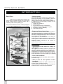
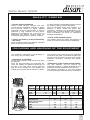
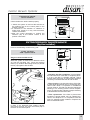
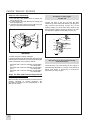
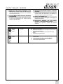
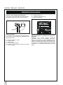
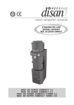
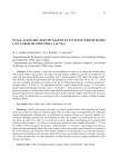
Central Vacuum Systems
OWNER’S MANUAL
CENTRAL VACUUM CLEANERS
DS MODULAR
MOD. DS A01
MOD. DS B02
MOD. DS C03
MOD. DS D02
MOD. DS F03
MOD. DS HK175i
MOD. DS B01
MOD. DS BC100i
MOD. DS CD125i
MOD. DS EF125i
MOD. DS H02
© Copyright by DISAN S.r.l.
Technical drawings and layout: Disan S.r.l.
Any unauthorized reproduction, even partial, is
forbidden.
Photos, drawings and descriptions in this handbook reflect the state of the art at the moment
when this catalogue was printed. The company
Disan reserves the right to update its production,
previous catalogues and handbooks. For further
information, please contact “DISAN”’s technical
office.
Disan acknowledges a 2 years guarantee for parts
having manufacturing defects. The guarantee is
valid only if the instructions set out in this handbook are fully complied with.
Ediz. 2011 • Printed in Italy • A. Weger
INDEX
Introduction
4
Quality controls
5
Unloading and handling of the power unit
5
Technical features and main parts
6
Central vacuum cleaner DS A01 100 l – 125 l – up to 1 operator .. 6
Central vacuum cleaner DS B01 100 l – 125 l – up to 2 operators 6
Central vacuum cleaner DS B02 100 l – 125 l – up to 2 operators 6
Central vacuum cleaner DS BC100i - 100 l – up to 2+1 operators 6
Central vacuum cleaner DS C03 100 l – 125 l – up to 3 operators 7
Central vacuum cleaner DS CD125i - 125 l – up to 3+1 operators 7
Central vacuum cleaner DS D02 100 l – 125 l – up to 4 operators 7
Central vacuum cleaner DS EF125i – 125 l – up to 5+1 operators 7
Central vacuum cleaner DS F03 125 l– up to 6 operators ............. 7
Central vacuum cleaner DS H02 175 l– up to 8 operators ............ 7
Central vacuum cleaner DS HK175i – up to 8+1 operators ............ 7
Technical data of the central vacuum cleaner ................................ 8
Main parts....................................................................................... 9
Optional parts
10
Installation of the power unit
11
Regular maintenance (by the person in charge of the central
vacuum system)
15
11
Regular filter cleaning ............................................ 11
Emptying of the dust container................................ 11
Check of the functioning of the automatic filter
shaker..................................................................... 12
Check of the functioning of the turbine ................... 13
Extraordinary maintenance
13
Filter control and replacement ............................... 13
Check of the lid tight ............................................... 14
Sequence of the starting of the turbines ................ 14
Safety instructions
15
Troubleshooting
16
Identification data
18
Check list for the installer
19
Yearly maintenance contract
19
Certificate and guarantee terms
20
3
Central Vacuum Systems
INTRODUCTION
Dear Client
Thank you for trusting and choosing our
brand. We are confident that the use of this three
phase central vacuum cleaning system with a
modular system will fully satisfy you.
This product’s details have been carefully designed
so as to make it durable and always fully efficient.
• System quality
The components of the central vacuum cleaner have
been manufactured in full compliance with EU
directives on the safety of electrical systems.
Disan’s central vacuum cleaner was engineered for
a professional use, particularly focusing on the
following elements:
1. solidity and resistance;
2. suction power;
3. long life with minimum maintenance;
4. safety of the low voltage electric system;
5. technologic quality, reliability;
6. reduced dimensions.
• Purpose of these instructions
The use of the central vacuum cleaning system is
very simple and does not require specific technical
knowledge. Nevertheless, a number of instructions
have to be carefully followed in order to avoid any
inconvenience during operation.
The purpose of this handbook is to convey to
operators the fundamental criteria for the operation
of the system. A table of failures at the end of this
handbook helps troubleshoot the causes of
malfunctions, if any.
Please treat this handbook with care and keep it for
future reference.
• Appointment of the person in charge of
the system
We suggest to nominate a person in charge of the
vacuum cleaning system, who attends to the
emptying of the dust canister and to the maintenance
of the system, who teaches cleaners how to use the
system and who serves as an interlocutor with the
technical assistance (to be provided by the installer).
• Loss of the handbook
If you lose or damage this handbook, ask the installer
for another copy.
• State of the art and updates of this
handbook
This handbook reflects the state of the art at the
moment when it has been printed.
The manufacturer reserves the right to update its
products and the corresponding handbooks.
4
Central Vacuum Systems
QUALITY CHECKS
It is the purchaser’s responsibility always to control
the goods on delivery and check that they
were not damaged during their transport. If a
damage is found, accept the goods with
reservation, specifying your observations on the
delivery note. In case of damage of the material,
inform immediately the carrier for subsequent
damage compensation.
• Checks during production
Disan’s central vacuum cleaners and their
components are repeatedly subjected to quality
and functional checks by highly qualified
technicians during its manufacturing, in order to
guarantee a long operation life and perfect
operation for professional use. In this way it is
guaranteed that Disan’s products leave the
manufacturing department in perfect conditions.
• Check of the finished system
• Checks on delivery (to be performed by
the client)
The installer checks the system and performs a
series of functional checks during its installation.
All the material shipped was carefully controlled
before its delivery to the forwarder.
UNLOADING AND HANDLING OF THE EQUIPMENT
The modulus of the motor suction are separately
furnished on the pallet. In the waste container you
will find a pipe connection for the dust and motor
separator, connection couplings and tighten
wrappers.
This handbook is attached to the packaging in
such a way as to be clearly visible.
• Indications on handling
Lift the pallet carefully using the lift truck fitting
this purpose.
Since the dust separators are particularly tall,
check the stability and balanced positioning of
the load on the forks. When moving, keep the
load as low as possible for more stability and
visibility, then operate with the maximum caution.
• Dimensions of the central vacuum cleaner
The dust separator and the motor(s) are
separately mounted on pallets designed for this
purpose and shrink-wrapped and box packing.
The following calculation of sizes and weights
includes packaging. Measures are in centimeters.
Z 820
H
W
D
Engines
A01
Weight kg
Width
Depth
Height
78
B01 BC100i CD125i EF125i B02
C03
D02
F03
185
190
80
120
162
358
532
94
80
120
75
Dust separator
H
D
Weight without automatic
filter-shaker kg
Weight with automatic
filter-shaker kg
Width
Depth
Height
192
260
80
120
132
135
H02
HK
465
80
120
219
367
80
120
142
Separator 100l Separator 125l Separator 175l
57
95
–
62
100
173
86
70
175
86
70
175
95
88
216
W
5
Central Vacuum Systems
CHARACTERISTICS OF THE CENTRAL VACUUM
CLEANER AND MAIN PARTS
Central vacuum cleaner
model DS A01 100l – 125l
1 x 2,2 kW for 1 operator
Code A100 – A125
Central vacuum cleaner consisting of:
- one silenced SIEMENS turbine with three-phase side
channel motor without transmission, secured on a
metal frame, IP55 safety degree;
- cyclonic dust separator in steel, painted with epoxy
powder, secured on a metal frame, filter chamber
equipped with industrial-conceived star filter made of
special polyester cloth with high withholding properties, deflector for the mechanical-gravitational separation of dust, dirt receptacle on wheels with disposable
plastic bags and cushioned fasteners, safety and
compensation system in the dust bag, manual filter
shaker;
- electric control box with IP56 safety degree, realized
in accordance with CEI norms, with low-voltage (12 V)
outlet and equipped with electric chart for linkage;
- connections for correct linkage to the piping network
and all other parts and accessories for the professional setting of the system;
- CE certificate.
Central vacuum cleaner
model DS B01 100 l – 125 l
1 x 5,5 kW for 2 operators Code B100ST – B125ST
Central vacuum cleaner consisting of:
- one silenced SIEMENS turbine with three-phase side
channel motor without transmission, secured on a
metal frame, IP55 safety degree;
- cyclonic dust separator in steel, painted with epoxy
powder, secured on a metal frame, filter chamber
equipped with industrial-conceived star filter made of
special polyester cloth with high withholding properties, deflector for the mechanical-gravitational separation of dust, dirt receptacle on wheels with disposable
plastic bags and cushioned fasteners, safety and
compensation system in the dust bag, manual filter
shaker;
- electric control box with IP55 safety degree, realized in
accordance with CEI norms, with low-voltage (12 V)
outlet and equipped with electric chart for linkage;
- connections for correct linkage to the piping network
and all other parts and accessories for the professional setting of the system;
- CE certificate.
Central vacuum cleaner
model DS B02 100 l - 125 l
2 x 2,2 kW for 2 operators
Code B200 – B225
Central vacuum cleaner consisting of:
- Two silenced SIEMENS turbines with three-phase side
channel motor without transmission, secured on a metal
frame, IP55 safety degree;
- cyclonic dust separator in steel, painted with epoxy
powder, secured on a metal frame, filter chamber
equipped with industrial-conceived star filter made of
special polyester cloth with high withholding properties, deflector for the mechanical-gravitational separation of dust, dirt receptacle on wheels with disposable
6
plastic bags and cushioned fasteners, safety and
compensation valves, arranged for pressure compensation system in the dust bag, manual filter shaker;
- electric control box with IP55 safety degree, realized in
accordance with CEI norms, with low-voltage (12 V) outlet
and equipped with electric chart for linkage;
- connections for correct linkage to the piping network
and all other parts and accessories for the professional setting of the system;
- CE certificate.
Central vacuum cleaner
model DS BC 100i
+
1 x 4,5 kW for 2+1 operators
Code BC100i
Central vacuum cleaner consisting of:
- one silenced SIEMENS turbine with three-phase side
channel motor without transmission, secured on a
metal frame;
- electronic inverter for continuous modulation of the
frequency and the other motor parameters with
electromagnetic shielding of type B (for applications
within the private and the industrial sector)
- cyclonic dust separator in steel, painted with epoxy
powder, secured on a metal frame, filter chamber
equipped with industrial-conceived star filter made of
special polyester cloth with high withholding properties, deflector for the mechanical-gravitational separation of dust, dirt receptacle on wheels with disposable
plastic bags and cushioned fasteners, safety and
compensation valves, arranged for pressure compensation system in the dust bag;
- automatic self-cleaning filter device through programmable shaking device;
- electric control box with IP55 safety degree, realized
in accordance with CEI norms, with low-voltage (12 V)
outlet and equipped with electric chart for linkage;
- Ø70 metal muffler for low noise level;
- connections for correct linkage to the piping network
and all other parts and accessories for the professional setting of the system;
- CE certificate.
Central vacuum cleaner
model DS C03 100 l – 125
3 x 2,2 kW for 3 operators
Code C100 – C125
Central vacuum cleaner composed of:
- three silenced SIEMENS turbines with three-phase
side channel motor without transmission, secured on
a metal frame, IP55 safety degree;
- cyclonic dust separator in steel, painted with epoxy
powder, secured on a metal frame, filter chamber
equipped with industrial-conceived star filter made of
special polyester cloth with high withholding properties, deflector for the mechanical-gravitational separation of dust, dirt receptacle on wheels with disposable
plastic bags and cushioned fasteners, safety and
compensation valves, arranged for pressure compensation system in the dust bag, manual filter shaker;
- electric control box with IP55 safety degree, realized
in accordance with CEI norms, with low-voltage (12 V)
outlet and equipped with electric chart for linkage;
- connections for correct linkage to the piping network
and all other parts and accessories for the professional setting of the system;
- CE certificate.
Central Vacuum Systems
Central vacuum cleaner
model DS CD 125i
+
1 x 5,5 kW for 3+1 operators
Code CD125i
Central vacuum cleaner consisting of:
- one silenced SIEMENS turbine with three-phase side channel motor
without transmission, secured on a metal frame;
- electronic inverter for continuous modulation of the frequency from 34
to 84 Hertz with electromagnetic shielding of type B (for applications
within the private and the industrial sector);
- cyclonic dust separator in steel, painted with epoxy powder, secured
on a metal frame, filter chamber equipped with industrial-conceived
star filter made of special polyester cloth with high withholding
properties, deflector for the mechanical-gravitational separation of
dust, dirt receptacle on wheels with disposable plastic bags and
cushioned fasteners, safety and compensation valves, arranged for
pressure compensation system in the dust bag;
- automatic self-cleaning filter device through programmable shaking
device;
- electric control box with IP55 safety degree, realized in accordance
with CEI norms, with low-voltage (12 V) outlet and equipped with
electric chart for linkage;
- Ø100 metal muffler for low noise level
- connections for correct linkage to the piping network and all other
parts and accessories for the professional setting of the system;
- CE certificate.
Central vacuum cleaner
model DS F03 125 l
3 x 5,5 kW for 6 operators
Code F125ST
Central vacuum cleaner consisting of:
- three silenced SIEMENS turbines with three-phase side channel
motor without transmission, star-triangle starting, secured on a metal
frame, IP55 safety degree;
- cyclonic dust separator in steel, painted with epoxy powder, secured
on a metal frame, filter chamber equipped with industrial-conceived
star filter made of special polyester cloth with high withholding
properties, deflector for the mechanical-gravitational separation of
dust, dirt receptacle on wheels with disposable plastic bags and
cushioned fasteners, safety and compensation valves, arranged for
pressure compensation system in the dust bag, manual filter shaker
predisposed for self-cleaning filter device;
- electric control box with IP55 safety degree, realized in accordance
with CEI norms, with low-voltage (12 V) outlet and equipped with
electric chart for linkage;
- connections for correct linkage to the piping network and all other
parts and accessories for the professional setting of the system;
- CE certificate.
Central vacuum cleaner
model DS H02 175 l
Central vacuum cleaner
model DS D02 100 l - 125 l
2 x 5,5 kW for 4 operators
Code D100 – D125
Central vacuum cleaner consisting of:
- two silenced SIEMENS turbines with three-phase side channel motor
without transmission, star-triangle starting, secured on a metal frame,
IP55 safety degree;
- cyclonic dust separator in steel, painted with epoxy powder, secured
on a metal frame, filter chamber equipped with industrial-conceived
star filter made of special polyester cloth with high withholding
properties, deflector for the mechanical-gravitational separation of
dust, dirt receptacle on wheels with disposable plastic bags and
cushioned fasteners, safety and compensation valves, arranged for
pressure compensation system in the dust bag, manual filter shaker;
- electric control box with IP55 safety degree, realized in accordance
with CEI norms, with low-voltage (12 V) outlet and equipped with
electric chart for linkage;
- connections for correct linkage to the piping network and all other
parts and accessories for the professional setting of the system;
- CE certificate.
Central vacuum cleaner
model DS CD 125i
- connections for correct linkage to the piping network and all other
parts and accessories for the professional setting of the system;
- CE certificate.
+
1 x 7,5 kW for 5+1 operators
Code EF125i
Central vacuum cleaner consisting of:
- one silenced SIEMENS turbine with three-phase side channel motor
without transmission, secured on a metal frame;
- electronic inverter for continuous modulation of the frequency from 34
to 84 Hertz with electromagnetic shielding of type B (for applications
within the private and the industrial sector);
- cyclonic dust separator in steel, painted with epoxy powder, secured
on a metal frame, filter chamber equipped with industrial-conceived
star filter made of special polyester cloth with high withholding
properties, deflector for the mechanical-gravitational separation of
dust, dirt receptacle on wheels with disposable plastic bags and
cushioned fasteners, safety and compensation valves, arranged for
pressure compensation system in the dust bag;
- automatic self-cleaning filter device through programmable shaking
device;
- electric control box with IP55 safety degree, realized in accordance
with CEI norms, with low-voltage (12 V) outlet and equipped with
electric chart for linkage;
- Ø100 metal muffler for low noise level
2 x 7,5 kW for 8 operators
Code H175ST
Central vacuum cleaner consisting of:
- two silenced double-V shaped SIEMENS turbines with three-phase
side channel motor without transmission, star-triangle starting,
secured on a metal frame, IP55 safety degree;
- cyclonic dust separator in steel, painted with epoxy powder, secured
on a metal frame, filter chamber equipped with industrial-conceived
star filter made of special polyester cloth with high withholding
properties, deflector for the mechanical-gravitational separation of
dust, dirt receptacle on wheels with disposable plastic bags and
cushioned fasteners, safety and compensation valves, arranged for
pressure compensation system in the dust bag, manual filter shaker
predisposed for self-cleaning filter device;
- electric control box with IP55 safety degree, realized in accordance
with CEI norms, with low-voltage (12 V) outlet and equipped with
electric chart for linkage;
- connections for correct linkage to the piping network and all other
parts and accessories for the professional setting of the system;
- CE certificate.
Central vacuum cleaner
model DS HK175i
+
1x11kW for 8+1 operators Code HK175i
Central vacuum cleaner consisting of:
- one silenced double-V shaped SIEMENS turbine with three-phase
side channel motor without transmission, secured on a metal frame;
- electronic inverter for continuous modulation of the frequency from 34
to 84 Hz with electromagnetic shielding type B;
- cyclonic dust separator in steel, painted with epoxy powder, secured on
a metal frame, filter chamber equipped with industrial-conceived star
filter made of special polyester cloth with high withholding properties,
deflector for the mechanical-gravitational separation of dust, dirt
receptacle on wheels with disposable plastic bags and cushioned
fasteners, safety and compensation valves, arranged for pressure
compensation system in the dust bag;
- automatic self-cleaning filter device through programmable shaking
device;
- electric control box with IP55 safety degree, realized in accordance
with CEI norms, with low-voltage (12 V) outlet and equipped with
electric chart for linkage;
- double Ø'3f100 metal muffler for low noise level;
- connections for correct linkage to the piping network and all other parts
and accessories for the professional setting of the system.
7
8
1x2,2
1x5,5
2
1x5,5
2
2x2,2
2
632
552
316
h
h
m3/
m3 /
Airflow max
Airflow @ 140 mbar
47,5
65
97
160
59,5
96
65
210
59,5
96
65
160
47,5
65
50
210
47,5
65
50
160
cm
cm
cm
l
Engine width
Engine depth
Engine height
153
157
153
157
153
cm
Separator height
63
72
63
72
63
cm
Separator depth
65
80
65
80
65
cm
Separator width
57
95
57
95
57
kg
Separator weight
19.500
45.000
19.500
45.000
19.500
Filter surface
100
125
100
cm2
capacity
l
Dirt receptacle
100
106
156
156
51,5
51,5
kg
Engine weight
125
68
78
78
68
68
dB
Sound level
440
407
407
224
224
552
320
360
360
320
320
mbar
Suction power
316
12
12
12
12
12
Filter chamber capacity
2x2,2
2
1x4,5
2+1
3x2,2
3
3x2,2
3
1x5,5
3+1
2x5,5
4
2x5,5
4
1x7,5
5+1
3x5,5
6
2x7,5
8
1x11
8+1
145
210
125
210
125
160
65
210
97
210
97
65
63
80
72
153
57
157
100
1810
1640
125
210
185
96
59
486
78
175
580
145
97
59,5
369
78
1470
380
360
1210
12
12
175
580
70
97
67
195
84
1220
1490
320
12
95
80
72
157
57
65
63
153
95
80
72
157
95
80
72
157
57
65
63
153
95
80
72
157
157
72
80
95
210
92
85
175
210
92
85
175
19.500 19.500 45.000 45.000 19.500 45.000 45.000 45.000 62.000 62.000
100
160
58
125
96
96
96
97
65
65
63,5
125
59,5
59,5
59,5
67
47,5
47,5
53
100
200
325
325
163
157
157
65
125
78
78
78
71
68
68
68
125
1036
805
805
223-784
655
655
165-565
95
45.000
125
210
97
65
47,5
106
68
440
160
1431
1100
1100
868
942
942
690
632
360
360
360
360
320
320
340
320
12
12
12
12
12
12
12
12
380-400 380-400 380-400 380-400 380-400 380-400 380-400 380-400 380-400 380-400 380-400 380-400 380-400 380-400 380-400 380-400
1x2,2
1
Volt
Volt
kW
1
Mod. Mod. Mod. Mod. Mod. Mod. Mod. Mod. Mod. Mod. Mod. Mod. Mod. Mod. Mod. Mod.
DS
DS
DS
DS
DS
DS
DS
DS
DS
DS
DS
DS
DS
DS
DS
DS
F03 H02
A01 A01 B01 B01 B02 B02
CD
C03 C03
EF
D02 D02
BC
HK
100L 125L 100L 125L 100L 125L 100i 100L 125L 125i 100L 125L 125i 125L 175L 175i
requirement
Inlets voltage
requirement
Voltage
Nominal motor powe
Operators
Central vacuum cleaner
Mod. DS MODULAR
Central Vacuum Systems
Central Vacuum Systems
Main parts
1. Frame of the motor 2,2 kW
Frame of the motor 5,5 / 7,5 / 11kW
2. Suction motor 2,2 kW
Suction motor 5,5 kW
Suction motor 7,5 kW
3. Support foot 2,2 kW
Support foot 5,5 kW/7,5kW /11kW
4. Flexible Air tube 100 l
Flexible Air tube 125-175 l
5. Rubber hose 2,2kW Ø70mm
Rubber hose 7,5kW Ø100mm
6. Hose-coupling 2,2kW Ø70mm
Hose-coupling 5,5kW Ø100mm
Hose coupling 7,5kW Ø100mm
7. Cap 2,2 kW Ø70mm
Cap 5,5 kW Ø100mm
Cap 7,5 kW Ø100mm
8. Filter chamber 100 l
Filter chamber 125 l
Filter chamber 175 l
9. Visual indicator “too full” 100 l
Visual indicator “too full” 125-175 l
10.Lever Open/Close
dust container 100 l
Lever Open/Close
dust container 125-175 l
11. Frame support sep. 100 l
Frame support sep. 125 l
Frame support sep. 175 l
code IE102
code IE101
code CE660
code CE662
code CE663
code CE111
code CE111
code CE211
code CE212
code CE412
code CE411
code CE908
code CE909
code CE909
code CE450
code CE451
code CE451
code CE702
code CE701
code CE713
code CE213
code CE214
code CE215
code CE216
code CE217
code CE218
code CE219
12. Knob of filter shaker 100 l
code CE706
Knob of filter shaker 125 l
code CE707
13. Bracket blocking the knob 100 l
code CE708
Bracket blocking the knob 125-175 l code CE709
14. Cover 100 l
code CE700
Cover 125 l
code CE703
Cover 175 l
code CD704
15. Cover locking clasp 100 l
code CE710
Cover locking clasp 125-175 l
code CE710
16. Separator handle 100 l
code CE711
Separator handle 125-175 l
code CE712
17. Dust container 100 l
code CE317
Dust container 125-175 l
code CE318
18. Wheels 100 l
code CE219
Wheels 125-175 l
code CE220
19. Main electric control box
· Mod. DS A01
code IE201
· Mod. DS B01
code IE203
· Mod. DS B02
code IE202
· Mod. DS C03
code IE204
· Mod. DS D02
code IE208
· Mod. DS F03
code IE209
· Mod. DS H02
code IE218
20. Automatic filter-shaker device
code IS92
100L + control box
Automatic filter-shaker device
code IS01
125-175 l + control box
21. filter cleaner device wire for IS01code IS91
Z 821
5
12
13
14
4
19
4
15
5
8
1
6
9
16
2
17
10
6
3
7
11
18
21
19
20
Mod. DSB02 125 l
9
Central Vacuum Systems
LIST OF OPTIONALS
Automatic self-cleaning
filter
device
with
electronic card. This
device permits the automatic, daily cleaning of
the filter, thereby always
guaranteeing its full
vacuum efficiency.
- Mod. with separator
100 l
code IS92
- Mod. with separator
125-175 l code IS01
Z 822
Plastic bags for dust
collection,
20-piecepackage.
- Mod. with separator
100 l
code IE601
- Mod. with separator
125-175 l code IE602
Z 222
Zinc-coated muffler with
couplings
- Diam. 70 mm
code IS10
- Diam. 100 mm
code IS11
Z 279
Inlet resistance
4700 Ω
code IS06
Grill and pipe complete
with two plastic bags.
It allows the insertion in
the dust container of the
plastic bags to collect
the dust
- Mod with separator
100 l
code IE601
- Mod with separator
125 l
code IE602
Cyclone
The
upper
cyclone
protects the filter and
improves dust storage
inside the container.
- Mod. with separator
100 l
code IS08
Electronic
control-sequential
starting device.
- 2 motors
code IS02
- 3 motors code IS03
Z 277
Z 278
Z 287
Z 288
For their installation, please see the instructions attached to each optional.
10
Central Vacuum Systems
INSTALLATION OF THE CENTRAL VACUUM CLEANER
The central vacuum cleaner must be installed and
hooked up by an authorized installer. Instructions
for a correct installation of the system are given in
the corresponding handbook “DESIGN INSTALLATION – INSPECTION OF DS SUPER
COMPACT AND DS MODULAR SYSTEMS”.
ORDINARY MAINTENANCE
(by the person in charge of the central vacuum cleaner)
Filter self-cleaning system
Regular filter
cleaning
The system works perfectly only if the filter in the
filter chamber is cleaned with particular care.
Cleaning operations are carried out when the
system is switched off.
If you intend to empty the dust container or the
plastic bag after cleaning, first operate the filter
cleaning devices and then wait a few minutes for
the dust to deposit on the bottom of the container.
Manual operation
Manual cleaning of the filter must be carried out at
regular time intervals, depending on the use of the
system (e.g. every 3-34 weeks if the system is
used daily), before emptying the dust container or
in any case if you notice a reduction in suction
power.
An automatic filter shaking device (optional) is
available for three-phase central vacuum
cleaners, ensuring the automatic self cleaning of
the filter every 12-24 hours.
- To start the command-operated filter shaking
device, press the switch (21) on the control panel
of the shaker. We suggest performing this
operation before emptying the dust container
and in any case if you notice a reduction in
suction power.
- The automatic shaking device works only when
the system is switched off.
Please notice: shaking times exceeding one
minute do not improve cleaning but do contribute
to an early wear of the filter.
Z 824
21
Sequence procedure
1. Lower the blocking bracket (13).
2. Energetically raise and lower the knob (12) with
one hand, several times (approx. 10-15 times).
3. Bring back the blocking bracket (13) to its
original position.
Z 823
12
13
Emptying of the
dust container
It is essential to control the dust level every month.
Dust may be collected directly in the container or
in the plastic bag fitting this purpose. If necessary,
dispose of the dust in compliance with the rules
envisaged for separate waste collection and
replace the bag. Before emptying, shake the filter
(see “Regular filter cleaning”).
Wait a few minutes for the dust to deposit on the
bottom of the container.
11
Central Vacuum Systems
Sequence procedure
In the containers without dust bag the visual
indicator (9) shows how full the dust container (17)
is and when it is covered by dust it must be
emptied.
1. Release slowly the lever (10) until when the
wheels of the container (17) are perfectly leant
on the floor.
3. Reinsert the container by setting it under the
vacuum cleaner. Please pay attention that the
visual indicator (9) remains outside. Push the
lever to the bottom so that the container (17)
goes up so that it fits tightly again in the filter
chamber (8). During the operation of hooking of
the dust container, please pay attention not to
crush the suction pipe.
Z 827
8
Z 825
10
9
17
17
2. Grasp the handle (16) and extract the container
(17). Empty the container or replace the plastic
bag (20).
Functional check of the
automatic filter shaking device
Check whether the filter shaking device works
properly:
Plastic bag for separator 100 l
code IE601
Plastic bag for separator 125-175 l
code IE602
Z 826
1. Keep pressed for a few seconds button (21) on
the control panel of the shaker.
2. If noisiness or the emission of vibrations is
higher than normal or in any case excessive,
contact the installer.
Z 824
21
20
16
17
Please notice: The insertion of the plastic bag in
the dust container is possible only through the
installation of the grill and pipe (see attached
instruction of the article)
Griglia e depressore per separatori l 100 Cod. IS05
Griglia e depressore per separatori l 125 Cod. IS07
12
Central Vacuum Systems
Z 828
Functional check
of the turbine
Check whether the turbine works properly:
1. Switch the system on and set the switches of
the turbines (22) on the control panel in the
position “manual”.
2. If noisiness or the emission of vibrations is
higher than normal or in any case excessive,
contact the installer.
3.After the control remember to replace the
switches (22) of the turbine control in the
position “automatic”.
22
EXTRAORDINARY MAINTENANCE
(by the installer)
Perform the following controls every year:
Z 830
Filter control
and replacement
Stages to disassemble the lid:
While the system is switched off, detach the hose
(4) from the lid fitting (23). Lower the blocking
device (13). Unblock the locking hooks (15) and lift
the lid (14) together with the filter.
25
24
Z 829
23
4
13
14
15
- Checking the filter conditions: check whether
the internal surface of the filter is completely white.
If it isn’t, the filter is probably pierced. Check
whether there are holes. To check, follow the steps
necessary to disassemble the lid and the filter.
- Filter cleaning: if the internal surface of the filter
is white while the external one is excessively dirty,
clean it with a brush, a compressor or a traditional
vacuum cleaner. The filter can also be cleaned by
washing it in a washing machine at low temperatures. To clean the filter, follow the steps necessary
to disassemble the lid and the filter.
- Filter replacement: if the filter is pierced and
therefore no longer usable, put it in a plastic bag,
close it and dispose of it in compliance with the
rules for separate waste collection. Replace the
filter as described below.
If there is an automatic filter shaking device,
disconnect the plug (24) from the socket (25) on
the back of the control panel.
13
Central Vacuum Systems
Steps for filter dismantling:
1. Turn the filter (26) upside down to expose the
fixing clamps (27).
2. Cut the clamps (27) and detach the housing (28)
from the filter (26).
3. Unscrew the clamp (29) from the filter ring (30),
remove it from the filter and set aside.
Z 831
27
Control of the tight
of the lid
Control the tight of the lid (14) with the filter
chamber (8). If the seal under the lid (14) has given
way unscrew the blocking screws (31) of the
locking clasps (15), and make them slide to the
bottom until the perfect closing of the lid (14). After
this operation tighten the blocking screws (31).
Z 832
30
28
14
29
31
15
26
!WARNING!
The filter must be carefully replaced.
It must be replaced by another filter with the same
characteristics, otherwise you risk jeopardising the
correct operation of the vacuum cleaner.
Star filter with a 460 mm diameter for separator
160 l
Cod. ER17080
Star filter with a 560 mm diameter for separator
210 l
Cod. ER17081
Star filter with a 780 mm diameter for separator
580 l
Cod. ER17082
Steps for filter and lid mounting onto the
central vacuum cleaner:
Mount the filter and the lid onto the central vacuum
cleaner following in reverse sequence the
procedure indicated for the disassembly of the
filter and of the lid.
14
8
Sequence of the functioning
of the motors
The sequence of the functioning of the engine is
automatically adjusted by a meter in the electrical
panel. This allows a functioning in work-hours
equivalent for every engine.
Central Vacuum Systems
SAFETY INSTRUCTIONS
(read carefully)
Failed observance of the safety instructions may
compromise the operation of the system or
seriously damage it. The following “safety instructions” contain essential indications for the system’s
safety and for the safety of the people using it.
System’s safety prearranged during its
production
The vacuum cleaner was made paying particular
attention to the safety of operators. Each component was designed on the basis of strict safety
guarantees which Disan has adopted.
Electrical safety
FConnect the central vacuum cleaner only to a
current with the same tension indicated on the
“identification data” plate (see chapter “IDENTIFICATION DATA”, page 18) .
F Establish the electrical connection provided
with efficient grounding and with a neutral
phase.
F The safety of the electronic system is guaranteed only if there is a suitable safety ground
fault circuit-breaker complying with the regulations in force.
!WARNING!
For models with electronic inverter it’ s necessary
to provide a safety switch (FI) of 300mA at least.
System’s safety
F Before using it for the first time, make sure – via
the installer - that the entire system works
perfectly.
F Do not expose the central vacuum cleaner to
the direct action of the weather (e.g. rain, snow
F Check at regular time intervals the dust
container or the plastic bag, if the machine is
provided (see paragraph “Emptying of the dust
container”, page 11).
F At regular time intervals, shake the filter
manually (see paragraph “Periodic filter
cleaning”, page 11).
F Never vacuum-clean without having the filter
installed and, under any circumstance, use only
original Disan star-filters
F Leave always the switch of the electric box in
the position “automatic”.
F Do not start the system when out of order.
Technical assistance
F If the green light signalling connection to the
mains (at the centre of the control panel)
remains on and if the causes of the failed
operation cannot be found among those listed
in the “TABLE OF FAILURES”, page 16, please
contact your dealer or an authorised installer.
F Any intervention must be carried out only when
the system is switched off and disconnected
from the mains.
FWe suggest checking the system and
overhauling the central vacuum cleaner every
4-5 years.
!WARNING!
Safety devices must never be tampered with!
15
Central Vacuum Systems
TROUBLESHOOTING
The ground fault
circuit-breaker trips
The system turns on
and off intermittently
The system remains
on
The system does
not start
Low vacuum
power
No vacuum
power
The inlet socket
whistles
SYMPTOM
CAUSE
1 Filter clogging
2 Hose clogging
3 Wrong closing of the dust container – cyclone’s gasket
(optional) damaged or out of place
4 Simultaneous use of several inlet sockets
5 Tubes clogging – air infiltration
6 Thermal contact breaker
7 Defective or dirty microswitch of the socket
8 Wear of the inlet socket’s contacts
9 12 Volt mains lead to inlet sockets
is damaged
10 Defective electric parts– motor failure
11 Dust container full
12 Defective gasket of the inlet socket – protruding screws
1. FILTER CLOGGING
If suction power at the inlet socket is low, the
filter may be excessively clogged.
In this case:
- if the machine has a manual shaking device,
clean it as indicated on page 15;
- if it equipped with an automatic shaking
device, see page 11.
2. HOSE CLOGGING
If the suction power at the inlet socket is good,
clogging is in the hose or in the brushes. If – on
the contrary - suction power at the inlet socket is
weak, clogging is
a. in the socket (visible to the naked eye)
b. in the tubing (see item 5)
If necessary, clean them manually (for precaution, wear latex gloves, as those used in the
kitchen).
3. WRONG CLOSING OF THE DUST CONTAINER – CYCLONE’S GASKET (OPTIONAL)
DAMAGED OR OUT OF PLACE
After emptying, make sure that the dust
container closes tightly to avoid suction power
reductions. Furthermore, check that the gasket
is positioned correctly and that it is not damaged.
4. SIMULTANEOUS USE OF SEVERAL INLET
SOCKETS
The central vacuum cleaners are designed for a
number of operators depending on the model of
the machine. The simultaneous use of several
inlet sockets on the same network entails a
considerable suction power reduction.
16
5. TUBES CLOGGING – AIR INFILTRATION
If the procedures listed under 1,2,3 and 4 do not
increase the air flow rate, clogging is in the
tubing. (caused by punctures, drillings, or nails
driven into the wall).
If the system is provided by sphere valve for the
manual closing of the different pipe lines, close
the valve corresponding to the defective line
until the intervention of the installer. The system
can be used on the pipe line corresponding to
the others closing valves.
6. THERMAL CONTACT BREAKER
The contact breaker (the main switch) blows
when
- the vacuum motor has been subjected to a
considerable electric current overload;
- the motor is defective;
- the motor has overheated due to filter
clogging, clogging of the tubing or a narrowing
in the breather pipe.
Before switching the system on again, wait 8-10
minutes for the motor to cool down. If after completing the procedures as of items 1, 2 and 5 the
switch continues to trip, switch the system off
and contact your installer
7. DEFECTIVE OR DIRTY MICROSWITCH OF
THE SOCKET
If the central vacuum cleaner remains
switched on or does not start despite the
closing or opening of the inlet socket, check
whether the microswitch on the socket itself
works properly. If you cannot find the cause,
contact your installer.
Central Vacuum Systems
8. WEAR OF THE INLET SOCKET’S CONTACTS If the system does not start and you
use inlet sockets with contacts, check whether
the contacts are worn.
9. 12 VOLT MAINS LEAD TO INLET SOCKETS
IS DAMAGED
It happens rarely that the mains lead connecting the inlet sockets to the central vacuum
cleaner gets damaged.
10. DEFECTIVE ELECTRIC PARTS – MOTOR
FAILURE
If the procedures listed above do not start the
vacuum motor, the cause lies in the damage of
an electric part. Contact your installer.
11. DUST CONTAINER FULL
Empty the container (see page 11 “Emptying of
the dust container”)
12. DEFECTIVE GASKET OF THE INLET
SOCKET – PROTRUDING SCREWS
Replace the gasket or tighten the screws
correctly
Clogging of the tubes – air infiltrations
ANALYSIS
Drop in
suction
power
insufficient
suction
PROGNOSIS
clogged
air infiltrations
REMEDY
1A Open the dust container
1B Vacuum the other way round, connecting a powerful vacuum
cleaner to the inlet sockets
2 Explore the tubes with a spiral probe (used for plumbing
works)
3 Contact Disan’s technical office
1A If there is no noise, switch on the system keeping the inlet
sockets closed
1B Locate the source of whistling due to air infiltrations
2 Use the suitable inspection camera (code GE903)
3 Contact Disan’s technical office
17
Central Vacuum Systems
IDENTIFICATION DATA
Position of the identification data plate
The position of the identification data plate indicating
the machine’s data is as shown in the picture:
G = supply tension (V)
H = operating frequency (Hz)
I = year of construction
Z 834
Z 833
00
22
330
30
A
9S
3
X
50
64
0
28 6
50
B
DS B01 100 l
0 0 610 I
B100ST
D
5,5
3
G
380
50
C
E
2850
F
H
X
I
Data on the plate
All technical and construction data pertaining to
your central vacuum cleaner are indicated on the
identification plate.
A = vacuum cleaner’s model
B = serial number
C = article code
D = motor absorption (kW)
E = number of revolutions per minute of the motor
F = motor’s stages
18
Data identification for assistance or guarantee
purposes
Whenever you contact Disan’s “technical
assistance service” or the installer, specify the
data of your machine. A clear indication of the
“machine’s model” and of the “serial number” will
help the constructor answering you and will avoid
inaccuracies or mistakes. Please refer to the data
indicated in your guarantee certificate (see last
page).
Central Vacuum Systems
CHECK LIST FOR THE INSTALLER
Check of inlet socket’s tightness
Check of the turbine’s operation
Check of the starting of the system at the
inlet sockets
Check of the functioning of the starting
device system*
Check of the wear of vacuum cleaning
accessories
Check of the correct adjusting of the
by-pass valves
Check of the suction value
Inversion of sequence of the starting of
the turbines.
Filter check and cleaning
* if available
Check of the functioning of the automatic
filter-shaking device*
YEARLY MAINTENANCE CONTRACT
We suggest entrusting your installer with the yearly maintenance
of the modular systems in order to always keep the system at its maximum efficiency
19
e
t
a
c
i
f
i
t
r
a
r
a
Gu
e
c
e
nte
To be filled in by the manufacturer
Tested by:
Model:
Serial number:
GUARANTEE CERTIFICATE
!IMPORTAN T!
Please send us this card, filled in, within
30 days to allow the recording of your
guarantee right.
Guarantee certificate
Seller’s stamp and signature
Model:
Date of purchase:
Serial number:
Purchaser’s name and address:
24 MONTH GUARANTEE
GUARANTEE TERMS
Terms valid when purchased
The central vacuum cleaner has been delivered to
the user under the terms in force at the time of
purchase.
24 months
The Disan company undertakes to replace under
warranty the parts which have manufacturing
defects during a period of 24 months from their
date of purchase.
Guarantee certificate
The guarantee is valid if the detachable coupon
(see last page, GUARANTEE CERTIFICATE) is
filled-in in a readable way and is returned within 30
days maximum from the date of purchase.
Contact your installer
For any abnormal condition, please contact your
installer, always indicating the identification data.
Disan’s reserve
For the guarantee to be acknowledged, the defective part must be sent to the Company’s seat in
Bolzano so that it can be tested at the technical
assistance laboratories. Disan reserves to establish
the cases when the defective parts meet the conditions allowing for a “replacement under warranty”.
Non acknowledgement:
For the guarantee to be valid, the instructions
contained in this booklet have to be compulsorily
followed.
Otherwise Disan may choose not to make the
repairs. Furthermore, the manufacturer holds
himself relieved from any liabilities for damage to
people and things resulting from non-compliance
in the following cases:
- incorrect installation;
- improper use of the central vacuum cleaner or of
the accessories;
- the foreseen maintenance has not been made or
has been made improperly;
- use of non original spare parts;
- total or partial inobservance of the instructions
for use;
- natural wear;
- attempts to disassemble, modify or in general
tamper with any component of the central
vacuum cleaner by the user or unauthorised
personnel;
- the guarantee certificate has not been sent in;
- non regular payment.
Area of Jurisdiction
The Tribunal of Bolzano (Italy) is exclusively
competent for any dispute.
Expenses charged to the client
Installation, disassembly and transport expenses
for the defective parts are charged to the purchaser.
Please
stamp
Srl
Central Vacuum Systems
Via di Mezzo ai Piani 13/A
39100 BOLZANO
ITALY
PR051(E)
Central Vacuum Systems
Disan S.r.l
I - 39100 Bolzano
Via di Mezzo ai Piani, 13/A
Tel. +39 0471/ 971000
Fax +39 0471/ 978888
e-mail: [email protected]
internet: www.disan.com