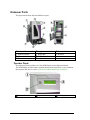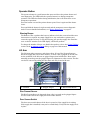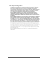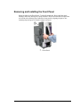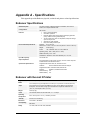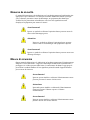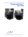
1
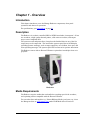
Endeavor ™ User Guide 110747-000, Rev. C Use this manual to help you: • Operate the Endeavor • Troubleshoot the Rimage Endeavor autoloader Notice for USA Federal Communications Commissions (FCC) Statement This device complies with Part 15 of the FCC Rules. Operation is subject to the following two conditions: (1) This device may not cause harmful interference, and (2) this device must accept any interference received, including interference that may cause undesired operation. Additional FCC Statement Any unauthorized modification to this equipment may result in the revocation by the FCC of the user’s authority to operate this equipment. Product Safety Statement This product is in compliance with UL 1950 3rd Edition. Notice for Canada Canadian Department of Communications (DOC) Statement This digital apparatus does not exceed the Class A limits for radio noise for digital apparatus specified in the Radio Interference Regulations of the Canadian Department of Communications. Product Safety Statement This product is in compliance with CSA C22.2 No.950. Notice for Europe European Standards This product is in conformity with the EMC Directive (89/336/EEC) and the LowVoltage Directive (73/23/EEC) through compliance with the following European standards: EN 60950, EN 55022, EN 50082-1. The CE mark has been affixed in accordance with the CE Marking Directive 93/68/EEC. In English: The information is provided in French, Italian, German and Spanish in Appendix B of this manual. En Français: L'information ci-dessus est répétée en français, italien, allemand et l'Espagnol dans l'annexe B de ce manuel. In Italiano: Le informazioni qui sopra sono ripetute in francese, italiano, tedesco e lo Spagnolo nell' appendice B di questo manuale. Auf Deutsch: Die Informationen oben werden auf französisches, italienisches, deutsch und spanisch in Anhang B dieses Handbuches wiederholt. En Español: La información arriba se repite en francés, italiano, alemán y español en el apéndice B de este manual. 2 Rimage Corporation 7725 Washington Avenue South Minneapolis, MN 55439 Service: (952) 946-0004 (International) (800) 553-8312 (North America) E-mail: [email protected] Technical Web Site: www.rimage.com/technical/ Fax: (952) 944-6956 Rimage Europe, GmbH Hans-Böckler-Straße 7 63128 Dietzenbach, Germany Tel: +49-(0) 6074-8521-0 FAX: +49- (0) 6074-8521-21 Record of Revisions - 110747-000 Revision Date Description B 09/26/03 Added PSS version 6.2, GemUtil version 5.2, and warning beeper information. C 3/9/04 Updated Printer Alignment Copyright© 2003 – 2004, Rimage Corporation. Rimage, Everest, and Endeavor are trademarks of Rimage Corporation. Perfect Image is a registered trademark of Rimage Corporation. All other trademarks and registered trademarks are the property of their respective owners. Changes The material in this document is for informational purposes only and is subject to change without notice. While reasonable efforts have been made in the preparation of this document to assure its accuracy, Rimage assumes no liability resulting from errors or omissions in this document, or from the use of the information it contains. Rimage is not responsible for inactive or changed website links, nor is it responsible for the content of any third party websites. Disclaimer YOU MUST OWN OR HAVE PERMISSION FROM THE COPYRIGHT OWNER OF ANY MATERIALS YOU COPY TO AVOID VIOLATING THE LAW, WHICH COULD RESULT IN DAMAGES OR OTHER REMEDIES AGAINST YOU. 3 Limited 1 Year Warranty Rimage warrants, to the original end user only, that all non-consumable parts of the Rimage Endeavor of automated products will be free from defects in material or workmanship for 12 months, according to the following terms: • Rimage will replace or repair, at Rimage's discretion, any non-consumable parts found defective within the Warranty period. • Valid from the date Rimage ships the product to you. • Factory depot repair to Rimage Minnesota or Rimage Germany with a typical response of 15 business days (25 business days for International). On-site repair, Advanced Replacement, or faster response Maintenance Contracts are available for an additional fee. • Rimage will pay ground service freight charges for components shipped to you. This Warranty Does Not include the following: • Work done at the customer's location, or customer's loss of data. • Shipment costs of equipment or components returned to the Rimage factory. • Software and/or firmware enhancements released after purchase of the product. • Equipment or parts that were tampered with, misused, neglected, or that were modified in any respect without the written consent of Rimage. • Equipment or parts that have been damaged due to shipping or accidents, or damaged by lightning, storms, water, or power surges. • Printer consumables including ribbons, ink cartridges, transfer sheets, or print head. You may not assign this Warranty without Rimage's written consent. Rimage is the intended beneficiary of this Warranty; if there is any inconsistency between this Warranty and any other agreement included with or relating to Rimage products, this Warranty shall govern. If any term of this Warranty is illegal or unenforceable, the legality and enforceability of the remaining provisions are not affected or impaired. This Warranty is to be interpreted under the laws of the State of Minnesota, without giving effect to conflict of law rules. Rimage must receive written notice of any claimed defect or failure to perform within five (5) days after such failure or defect is first observed. For warranty service, call Rimage at (952) 946-0004. The Limited Warranty set forth above is Rimage's only Warranty in connection with the Rimage Endeavor and Everest products. All other Warranties, whether written or oral, express or implied, contractual or statutory, including, but not limited to any Warranties of merchantability or fitness for any particular purpose are specifically excluded and disclaimed. In no event shall Rimage's liability under this Warranty exceed the obligation to repair or replace, at Rimage's discretion, a Warranted product, and, without limiting the foregoing, Rimage's liability under this Warranty shall not exceed the cost of the covered product. To check order shipment information, return goods data, shipping details, or tracking specifics on the Rimage web site go to www.rimage.com and select Order Status. 4 Table of Contents Limited 1 Year Warranty ..................................................................................................... 4 Precautions ........................................................................................................................... 6 Chapter 1 - Overview ................................................................................................................. 7 Introduction .......................................................................................................................... 7 Description............................................................................................................................ 7 Media Requirements............................................................................................................. 7 Endeavor Parts ..................................................................................................................... 8 Operator Panel ................................................................................................................ 8 Operator Button .............................................................................................................. 9 Lift Arm ........................................................................................................................... 9 Output Trays ................................................................................................................. 10 Output Bin..................................................................................................................... 10 Disc Output Configuration............................................................................................ 11 System Switches ............................................................................................................ 12 Cable Connections .............................................................................................................. 13 Chapter 2 – User Operations................................................................................................... 14 Introduction ........................................................................................................................ 14 Loading Discs ...................................................................................................................... 14 Installing Ribbons............................................................................................................... 15 Powering on Endeavor ....................................................................................................... 15 Power-Up Sequence Display Messages .............................................................................. 15 Remove Discs from Output Tray ....................................................................................... 16 Removing and Installing the Front Panel ......................................................................... 17 Chapter 3 - Maintenance ......................................................................................................... 18 Introduction ........................................................................................................................ 18 Preventive Maintenance Schedule..................................................................................... 18 Clean the Endeavor ............................................................................................................ 18 Printer Alignment .............................................................................................................. 18 Gemini Utilities .................................................................................................................. 22 Enable/Disable Warning Beeper ................................................................................... 22 GemUtil Help................................................................................................................. 22 Chapter 4 - Diagnostics and Error Messages.......................................................................... 23 Introduction ........................................................................................................................ 23 Starting Diagnostics ...................................................................................................... 23 Selecting a Diagnostic Test ........................................................................................... 23 Exiting Diagnostic Test................................................................................................. 23 Exiting Diagnostic Mode ............................................................................................... 23 Diagnostic Tests ............................................................................................................ 24 Operator Panel Error Messages.................................................................................... 28 Everest Printer Errors .................................................................................................. 29 Appendix A - Specifications ..................................................................................................... 31 Endeavor Specifications ..................................................................................................... 31 Endeavor with Everest II Printer ...................................................................................... 31 For More Information ........................................................................................................ 32 Appendix B - Safety Precautions............................................................................................. 33 Precautions ......................................................................................................................... 33 Mesures de sécurité. ........................................................................................................... 34 Misure di sicurezza ............................................................................................................. 34 Sicherheitsanweisungen..................................................................................................... 35 Medidas De Seguridad ........................................................................................................ 35 5 Precautions CAUTION Any equipment that has AC line voltage, or low DC voltages, such as switches, power supplies, fuses, fans, non-stepper motors, must be replaced with Rimage–approved components to maintain the safety approval issued by UL. WARNING The laser beam used by this CD-R recorder can be harmful to the eyes. Do not attempt to open the recorder. Do not attempt to view the laser beam. An authorized field technician should perform all service procedures. WARNING Never use any optical instrument in conjunction with this unit. To do so will greatly increase the hazard to your eyes. WARNING Please observe all warning and caution labels to ensure safety of personnel. WARNING Replace all fuses with the same voltage and current ratings to maintain UL safety approvals. WARNING Use the supplied AC power cord, or use a safety agency-approved power cord. 6 Chapter 1 - Overview Introduction This chapter introduces you to the Rimage Endeavor components, front panel operations and other user operations. For specifications, go to Appendix A on page 31. Description The Endeavor is a robotic-controlled CD-R or DVD-R autoloader ("transporter"). It has two recorders, a high quality thermal printer, a lift arm to move discs, and output trays to store completed discs. The system records and prints discs, then places the finished discs in one of the five output trays or the output bin. The autoloader's operator panel has an LCD display providing operator messages, such as empty supply bin, out of ribbon, door open, and other operating messages. The operator panel has one button for operator interaction. The Endeavor comes with an Everest II Printer to print discs in multiple colors or in grayscale. Endeavor Media Requirements The Endeavor requires media that can handle the recording speed of the recorders, and a printing surface compatible with the Everest II Printer. You can order discs and supplies (e.g., Printer Ribbons, Media, jewel cases, etc.) from the Rimage web site at www.rimage.com/ under CD-R Media select -Everest II. 7 Endeavor Parts The figure below shows the basic Endeavor parts. Everest II Printer Operator Button ! Operator Panel " Front Cover # Supply Door $ Supply Bin % Output Drop Bin & Output Trays ' Transfer Slides Recorder Operator Panel The Operator Panel provides a two-Line LCD Display and an Operator Button. The LCD Display provides status reporting during normal operation, or any condition that requires the user to resolve. A buzzer is employed that beeps on failures. Operator Panel Operator Button 8 ! LCD Display Operator Button The operator button is a push button that opens and closes the printer drawer and runs diagnostics. The LED inside the operator button is on during transporter operation. The LED also flashes during initialization, but is off when there are no transporter operations. Press the button once and the printer drawer opens. Press it again and the drawer closes. Press and hold the button for eight seconds and the transporter enters diagnostic mode. For more detailed information, see “Button Diagnostics” on page 23. Warning Beeper The Endeavor has a speaker that beeps to indicate a fault has occurred and that user intervention is required. An empty supply bin or any autoloader or printer error causes the speaker to beep. To stop the beeping, just open the supply door. Read the error on the PC monitor or the LCD display, and fix the problem. To change the number of beeps or to disable the speaker, refer to the Gemini Utilities section (in the # of Beeps on Fault dialog) on page 22 of this manual. Lift Arm The Lift Arm picks, transports, and releases discs. It has a Disc Present Sensor to detect the supply bin, the recorder drawers, or when a disc is gripped on the lift arm. At the underside of the lift arm are gripper fingers that hold the disc. Discs can be manually pressed up onto the gripper fingers for alignment or other reasons. The disc can also be removed by pulling the disc down and away from the lift arm. Lift Arm Gripper Fingers ! Disc Present Sensor Disc Present Sensor The Disc Present Sensor is depressed when a disc is secured on the gripper fingers. It is also used to detect the supply bin and recorder drawers. Door Sensor Switch The door sensor switch detects if the door is opened or if the supply bin is missing. If the supply bin is installed, it may not be seated firmly. Verify that the supply bin is in place. 9 Output Trays There are five output trays on the outside of the Endeavor. When a disc is recorded and printed, the lift arm moves to a tray position and releases the disc. The disc slides down and out to the end of the tray. There are sensors located on each output tray to detect if a disc is in the tray. See Disc Output Configuration” on page 11 to understand how discs are distributed to the output trays and output bin. The output trays are numbered 1 through 5, with #1 located at the top. Output Trays Output Bin Output Bin The output bin receives finished and/or failed discs. The output bin handles up to 75 discs. To remove discs from the output bin, hold the output bin with one hand while moving the Bin Latch up and lower the bin down. This provides easy access to the output bin to remove the discs. Lift the Output Bin with one hand and then pull the bin latch down to lock it in place. Do not use the latch to lift the output bin! Bin Latch 10 Output Bin Disc Output Configuration The Endeavor autoloader has five output trays numbered 1 through 5. Production Server software handles these trays in various ways depending on the settings. The Transporter Configuration tab in the Parameters dialog has a Mailbox combo-box with three options for the Endeavor outputs: “Output”, “Res. Output”, and “Don’t Use”. Refer to the Production Server online Helps for more information. When the Mailbox parameter is set to “Output”, the Production Server places completed discs in the first available tray, until all of the trays have a single disc. After that, completed discs are placed in the output bin, until one or more of the trays are emptied. When the Mailbox parameter is set to “Res. Output” (reserved output), the Production Server places discs in the trays only if the order specifies it. The order may specify a tray number (0 – 5) or ‘X’ (‘ANY’ in the messaging architecture). If the order specifies a tray number of ‘0’, or doesn’t specify, the completed disc will be placed in the Output Bin. If the order specifies a tray number of 1 – 5, then one disc can be placed in each tray. After each tray has a disc, the operator is prompted to remove the discs from the specified tray so more can be placed in that tray. If the order specifies tray ‘X’, then the completed disc is placed in the first empty tray and the order is updated with the tray number where the disc was placed. An order that specifies tray ‘X’ can only be set for 1 copy, since there is no way to report back multiple tray numbers in the order. Any order that specifies tray 1 – 5, or ‘X’, must also set the ‘target server’ and ‘target line’ fields in the order. When the Mailbox parameter is set to “Don’t Use”, no discs will be placed in the output trays. 11 System Switches Power Switch The Power Switch is located on the back corner of the Endeavor. The power switch controls the power for the Endeavor, which then supplies power to the Everest Printer. Voltage Selector Switch The voltage selector switch on the Everest printer must be set to match the AC voltage from the outlet. Selections are 110 VAC or 220 VAC. Mode Switch The Mode Switch is to set the operational mode of the Everest printer. The accepted positions are ‘0’ and ‘1’. After changing the mode switch, the printer must be powered on again to recognize the change. The recessed line on the switch indicates the selected mode. Power Switch ! Mode Switch " Recessed Line Voltage Selector Switch 12 Cable Connections Endeavor has cable connections coming out the back of the transporter frame and the Everest Printer that require connections. These connections are listed here, but the directions for connecting a PC are in the “QuickStart Instructions”. AC Power # Printer Power Cord $ Printer Control Cable Printer Control Cable ! Serial Control Cable (RS-232) " Firewire Cable 13 % USB Cable Chapter 2 – User Operations Introduction This chapter describes Endeavor setup, including: • Loading Discs • Installing Ribbons • Powering on Endeavor • Power-Up Sequence Display Messages • Remove Discs from Output Tray • Removing and Installing the Front Panel Loading Discs You can load up to 50 discs in the supply bin. Use thermal printable discs compatible with the Everest II Printer. 1. Open the autoloader door. 2. Hold the discs by the outer edge so you do not put fingerprints on either the top or the bottom surface and place them in the supply bin. Fingerprints on the top can affect printing. Ensure that the discs are oriented correctly. There is an extruded ridge called a stacking ring that can barely be seen, but can be felt, on one side of a disc. This ridge distinguishes the bottom of the disc. Some DVD-R discs have a stacking ring on both sides. Be sure to place the recording side facing down. Stacking Ring Orient the discs so the top of the disc is facing upward as shown above. 5. Close the door. 14 Installing Ribbons To install ribbons in the Everest Printer, stop any operations. Hold the side cover and press the two cover latches. Then allow the side cover to hinge open. See the Everest II Printer User Guide. Cover Latches Everest Printer ! Side Cover Powering on Endeavor Endeavor is powered on by a single switch at the back of the autoloader. Before powering on the Endeavor, be sure the print ribbons are installed, printer latches are closed, printer side cover is closed, and the front door is closed. Note: If this is the first time powering the system up, make sure the printer’s shipping screw was moved to the storage position. See the Everest Unpacking and Setup directions. The Endeavor must be powered on before the PC is started so the recorders are recognized by the Windows Operating System. Anytime the Endeavor is powered off, the PC must be rebooted so the recorders are recognized. Power-Up Sequence Display Messages When the Endeavor is powered on, the Endeavor proceeds through a sequence of messages, which are displayed on the Operator Panel. The LED in the operator button flashes during some of the initialization processes. When the autoloader has completed the initialization, the panel displays “EVEREST ENDEAVOR READY” and the LED inside the operator button is off. Here is the sequence of messages: 1. EXECUTING FLASH INITIALIZING 2. CHECKING FOR PRINTER 3. EVEREST PRINTER INITIALIZING 4. EVEREST ENDEAVOR READY 15 5. EVEREST PRINTER WARMING UP – The Everest printer takes about 5 minutes to warm up when it is first powered up. The LED is no longer flashing. 6. EVEREST ENDEAVOR READY If any error messages occur during the power up sequence, refer to the possible error messages on page 28. Note: The carrot symbol (^) in the upper right corner of the display indicates the Production Server is currently communicating with the Endeavor. Remove Discs from Output Tray Remove discs from the output tray by gripping the disc from the lowest edge as shown. If the disc is grabbed from the front edge, the disc above it may be lifted up over the stop of the output tray and slide out. Lowest Edge Front Edge 16 ! Stop Removing and Installing the Front Panel Grasp the sides of the Front Panel and pull straight out. Do not pull the panel sideways which may damage the operator button. The Front Panel has four pins that are held in with retaining clips. Install the front panel by aligning the pins to the retaining clips and press it in until it snaps in securely. – Front Panel 17 Chapter 3 - Maintenance Introduction This chapter provides the preventive maintenance required to keep the Endeavor running in top performance. The sections are: • Preventive Maintenance Schedule and Procedures • Cleaning the Endeavor • Printer Alignment • Run the GemUtil program Check the Rimage technical website at http://www.rimage.com/technical/ for additional documentation and procedures. Preventive Maintenance Schedule Maintenance Procedure Schedule Clean the Endeavor Once a week. Remove dust from Endeavor and surrounding work area. Clean Everest Print Head Clean Everest Printer Filter As needed, or at each print ribbon change. See the Everest Printer User Guide for specific cleaning directions. Dependant on environment. Clean at least every month. Refer to the Everest Printer User Guide for specific directions. Clean the Endeavor Clean the dust from the autoloader and the surrounding area. Clean the autoloader from dust once a week. The dust causes problems with printing the discs and the recording. It is best to place the Endeavor in a dust-free environment. Printer Alignment After installing the printer, it may need an alignment to the gripper arm. The alignment was initially done at the factory, but shipment may have shifted the original alignment. You will need a T10 Torx driver and a 5/32” Allen wrench. 1. Power on the Endeavor by pressing the Endeavor power switch. Wait for the unit to complete the initialization. The Everest Printer takes about 2 to 3 minutes to complete the initialization. 2. Press the operator button to open the Everest Print drawer. 3. Press and hold the operator button for 8 seconds. This places the Endeavor into diagnostic mode. The operator panel shows when to release the button. 4. Once the operator panel displays “01 CYCLE OUTPUTS DIAGNOSTIC”, press the operator button four times and hold on the fourth press. This selects the Jog Lift Diagnostic Test. The lift arm moves down closer to the print drawer. 18 5. Press the operator button one more time to move the disc closer to the print pad. 6. Insert a Disc up into the Lift Arm as shown below. The gripper fingers (not shown) will hold the disc. Lift Arm ! Print Pad Disc 7. Manually rotate the leadscrew counterclockwise to move the lift arm all the way down to the print pad. The disc should be placed in the print pad (recessed area). Leadscrew Lift Arm 19 8. If the disc is not centered side-to-side on the print pad, continue to step 9. You can see if the disc is not centered by observing the gap between the disc and the edges as shown by the arrows. If the side-to-side alignment is good, go to step 10. 9. To perform the side-to-side alignment procedure, loosen the two Torx side-to-side screws. Slide the printer, NOT the drawer, in small increments until the side edges of the disc and print pad are aligned. Then tighten the two Torx side-to-side screws. (The picture below shows the printer drawer closed so the adjustment screws can be seen.) Front-to-Back Alignment Screw 20 Side-to-Side Alignment Screws 10. Turn Front-to-Back Alignment Screw until there is a 1/16” (1.5mm) gap between the front edge of the disc and the raised edge of the disc retainer. Disc Retainer Gap Distance 11. Once the printer is aligned, rotate the leadscrew to raise the lift arm. 12. Pull the disc down from the gripper fingers. 13. Press and hold the operator button to exit diagnostic test 4. 14. Press the operator button fourteen times and hold on the last press to exit diagnostics. 15. Press the operator button once more to close the print drawer. 21 Gemini Utilities The Rimage Gemini Utilities program is used to update the controlling autoloader’s firmware and to check the number of discs printed. It can also be used to change the serial number of the autoloader and the name of the Endeavor. You must close Production Server before starting Gemini Utilities. To start Gemini Utilities, select Windows' Start|Programs|Rimage|Utilities|Gemini Utilities. When the autoloader is found, the Gemini Utilities dialog displays: Enable/Disable Warning Beeper Use the Gemini Utilities version 5.2.7.0 or above to enable the front panel LCD error warning beeper. Set the #of Beeps on Fault selection as desired. The factory default setting is 0 beeps (beeper disabled). GemUtil Help To open the GemUtil online help system, place the cursor over a Gemini Utilities item and then press the keyboard F1 key. Click on About to check the version. Click on Exit to close the Gemini Utilities program. The Status area provides the results of the last attempted operation. 22 Chapter 4 - Diagnostics and Error Messages Introduction This chapter provides Endeavor diagnostic testing and error message information. The Button Diagnostics allows you troubleshoot the Endeavor autoloader and components. The Button Diagnostics include: Diagnostic Test Page Diagnostic Test Page 01 – Cycle Outputs Diagnostic 24 08 – Door Open Diagnostic 27 02 – Cycle Media Diagnostic 24 09 – Output Tray 1 Diagnostic 27 03 – Calibrate Diagnostic 25 10 – Output Tray 2 Diagnostic 28 04 – Jog Lift Diagnostic 26 11 – Output Tray 3 Diagnostic 28 05 – Solenoid Test Diagnostic 26 12 – Output Tray 4 Diagnostic 28 06 – Lift Home Diagnostic 26 13 – Output Tray 5 Diagnostic 28 07 – Gripper Media Diagnostic 27 14 – Exit Test Mode Diagnostics 28 Starting Diagnostics If the autoloader is connected to the Control Center and the Production Server is running, there is a carrot symbol ‘^’ on the upper right corner of the LCD Display. 1. Press and hold the operator button about eight seconds and release the operator button when the display panel shows: “BUTTON DIAGNOSTICS” The operator panel shows “01 CYCLE OUTPUTS DIAGNOSTIC”. 2. Go to “Selecting a Diagnostic Test” section. Selecting a Diagnostic Test Press the operator button the number of times of the test number and hold on the last press to start the selected test. As you press the operator button, the panel shows the test number and name. To display each diagnostic test number and name, press the operator button at a slow rate just enough to read each test but do not hold down the button too long, otherwise the test starts. After a short time, the operator panel returns to test 01. If you have lost your count in selecting a test, just release the button and the operator panel returns to the first test. Exiting Diagnostic Test If an error message displays, locate the problem and fix any issues. Press the operator button to exit the error message. Exiting Diagnostic Mode See test 14 – Exit Test Mode Diagnostics on page 28. 23 Diagnostic Tests 01 – Cycle Outputs Diagnostic This test runs discs from the supply bin and places a disc in tray #1, the next disc into tray #2, and continues through tray #5, and then the output bin. Once the output trays are filled, the rest of the discs are placed in the output bin. The process stops when the supply bin is empty or the user presses the operator button. Place six discs in the supply bin to run one disc to each output tray and output bin. Press the operator button once to stop the test. 02 – Cycle Media Diagnostic This test has three modes depending on where a disc is placed or not placed: • Cycle a disc from recorder • Cycle disc from supply bin • Burn-in mode (no disc in the supply bin) Cycle a Disc from Recorder The printer must be aligned before running this test. 1. Open the recorder drawer by pressing the recorder’s button. 2. Place a disc on the recorder drawer. 3. Select Diagnostic #2. The process starts by detecting what elements (printer, or recorder) are in the autoloader. It moves the lift arm down to the recorder, and then moves the arm to the top of the lift. Opens the print drawer and closes it to see if there is a disc in the printer. The lift arm moves down to the recorder and retrieves the disc. The print drawer opens and the lift arm places the disc on the print drawer. The drawer closes and reopens, and the lift arm retrieves the disc. The lift arm moves the disc to the recorder and the cycle repeats until the operator button is pressed. Once the operation has stopped, the disc is moved to output tray #1. Cycle Disc from Supply Bin The printer must be aligned before running this test. 1. Place a disc on the recorder drawer. 2. Select Diagnostic #2. The process starts by detecting what elements (printer, or recorder) are in the autoloader. It moves the lift arm down close to the supply bin, and then moves the arm to the top of the lift. Opens the print drawer and closes it to see if there is a disc in the printer. The lift arm moves down to the supply bin and retrieves the disc. The print drawer opens and the lift arm places the disc on the print drawer. The drawer closes and reopens, and the lift arm retrieves the disc. The lift arm moves the disc to the supply bin again and the cycle repeats until the operator button is pressed. Once the operation has stopped, the disc is moved to output tray #1. Burn-in Mode 1. Close the recorder and print drawers if they are currently open. 24 2. Remove disc from the supply bin. 3. Select Diagnostic #2. The process starts by detecting what elements (printer, or recorder) are in the autoloader. It moves the lift arm down close to the supply bin, and then moves the lift arm to the top of the column. The Endeavor opens the print drawer and closes it to see if there is a disc in the printer. It moves the lift arm down to retrieve a disc from the supply bin. If the supply bin is empty, an error message displays (INPUT BIN NO MEDIA) on the operator panel and the LED flashes three times with a pause and repeats the flash cycle. Press the operator button again and the autoloader starts a lift arm cycle. This moves the lift arm up and down and counts the cycles until the button is pressed to stop the test. 03 – Calibrate Diagnostic This diagnostic test is to calibrate the distance of the lift arm homing position to the supply bin with one disc. Select the test and the panel displays “Press/Rel to Go Hold to Exit”. Press and release the operator button to start the calibration process. The panel displays the next step “PLACE ONE DISC TO SUPPLY BIN”. Place only one disc in to the supply bin and press the supply bin down to make sure it is properly seated. Press the operator button again. The lift arm moves down and picks the disc. It drops it back in the bin. The arm moves back above the print drawer. After this test is completed, the autoloader is calibrated. Endeavor restarts and it exits the diagnostic mode. 25 04 – Jog Lift Diagnostic Use this test to help align the printer and recorders. PRESS/REL to JOG HOLD to EXIT. After pressing the operator button, the motor energy is released so the Leadscrew can be rotated by hand to move the lift arm for finer movements. A disc can be placed in the gripper fingers to check alignments. See “Printer Alignment” directions on page 18. Press and hold the operator button to exit this test. Leadscrew Lift Arm ! Recorder Drawer 05 – Solenoid Test Diagnostic This test powers on and off the Gripper Finger Solenoid, which moves the gripper fingers. Press the operator button to stop the test. Gripper Finger Solenoid Lift Arm ! Gripper Media Sensor 06 – Lift Home Diagnostic This test is used to check the Lift Home Sensor located inside the lift arm. The sensor is blocked when the lift arm is at the top of the lift column. Once this test is selected, the leadscrew can be rotated by hand to move the lift arm up and down to test the 26 sensor. When the lift arm is at the top, the sensor is blocked. Move the lift arm down to unblock the sensor. Press the operator button to exit the test. Below is the bottom view of the lift arm. Lift Home Sensor ! Gripper Fingers Media Plunger/Disc Present Sensor " Lift Arm 07 – Gripper Media Diagnostic This test is to check the Disk Present Sensor located inside the lift arm. The sensor is blocked when the Media Plunger is pressed upward when a disc is gripped in the Gripper Fingers. Run this test and push up on the Media Plunger and the panel displays “Blocked”. Press the operator button to exit the test. 08 – Door Open Diagnostic This test is to check the Door Open Sensor located at the rear of the supply bin area. Run this test and close the door and the panel displays “Blocked”. Open the door and the panel displays “Unblocked”. Press the operator button to exit the test. Door Open Sensor Supply Bin 09 – Output Tray 1 Diagnostic This test is to check the Tray Sensor (optical reflective sensor) in the Output Tray. Tests 9 through 13 are selected for each tray sensor. Trays are numbered on the edge 27 of the tray with tray #1 located at the top. Select this test and place a disc in the tray and the panel displays “Blocked”. Remove the disc from the tray and the panel shows “Unblocked”. Press the operator button to exit the test. Tray Sensor Output Tray 10 – Output Tray 2 Diagnostic See diagnostic test #9. 11 – Output Tray 3 Diagnostic See diagnostic test #9. 12 – Output Tray 4 Diagnostic See diagnostic test #9. 13 – Output Tray 5 Diagnostic See diagnostic test #9. 14 – Exit Test Mode Diagnostics This is not a test, but it is used to exit the diagnostic mode and returns to the normal operation mode. Operator Panel Error Messages CLAMP FAILURE – the Everest Printer tried to clamp a disc but it failed. Check the alignment of the printer to the gripper fingers. ENDEAVOR PAUSED CHECK DOOR/BIN – Endeavor stopped all movements because the door is open. EVEREST PRINTER … – For an Everest Printer error, go to the “Everest Printer Error” section to locate the error and possible solution. NO PRINTER DETECTED – The printer’s serial cable is not connected to the autoloader, or the printer has no power. Check the cabling and the mode switch setting. The mode switch should be set to 0 or 1. 28 NO DISPENSER DETECTED – The dispenser is the mechanism that contains the output trays, transfer slides, and dispenser circuit board. The circuit board detects discs as they move down the transfer slide. Check the cable connection to the dispenser circuit board or connection to the internal circuit board. OUTPUT TRAY X OUTPUT FAIL – A disc was dropped into the #X output tray and the tray sensor detected that the disc did not slide past the tray sensor. This stops the autoloader from further movement. SUPPLY BIN NO MEDIA – The supply bin is empty. If the supply bin is not empty, run diagnostics test 03 to re-calibrate the lift arm movement. Everest Printer Errors Possible error messages from the Everest Printer that could display on the Endeavor operator panel: EVEREST PRINTER #1 NOT LOCKED – Open the Everest printer cover and close latch #1. EVEREST PRINTER #2 NOT LOCKED – Open the Everest printer cover and close latch #2. EVEREST PRINTER #3 NOT LOCKED – Open the Everest printer cover and close latch #3. EVEREST PRINTER CLAMPING FAILURE – Check the printer alignment so the discs can be clamped properly on the print drawer. EVEREST PRINTER CLOSING ERROR – The print drawer could not close. This is usually because the drawer was catching on something. Check the alignment of the printer and look for obstructions. EVEREST PRINTER COVER OPEN – Close the Everest printer cover. EVEREST PRINTER DATA ERROR – Label file could be corrupt or the label file was built by the wrong print driver. Check selected print driver, rebuilt the label, and try again. EVEREST PRINT DRAWER ENCODER – Send the Everest Printer to the factory for service. EVEREST PRINTER HALOGEN LAMP OUT – Halogen lamp in the Everest printer must be replaced. EVEREST PRINTER INK RIBBON GONE – The print ribbon is not installed and a ribbon must be installed. EVEREST PRINTER INK RIBBON SENSR – Clean the print ribbon sensor or send the printer to the factory for service. EVEREST PRINTER LOWER P.H. ERROR – Send the Everest Printer to the factory for service. EVEREST PRINTER NO MEDIA – The lift arm could not pick a disc off the printer. There was not a disc on the print pad or the printer is not aligned to the gripper fingers. The gripper solenoid may not be working or it needs adjustment. EVEREST PRINTER OPENING ERROR – The print drawer could not open or the drawer was hitting something. Check the alignment of the printer. 29 EVEREST PRINTER RAISE P.H. ERR. – Send the Everest Printer to the factory for service. EVEREST PRINTER RETRANSFER OUT – The retransfer ribbon is at the end of the roll and a retransfer ribbon must be installed. EVEREST PRINTER RETRANSFER GONE – The retransfer ribbon is not installed and a retransfer ribbon must be installed. EVEREST PRINTER RIBBON OUT – The print ribbon is out and a print ribbon must be installed. EVEREST PRINTER R.T. DOWN SENSOR – Send the Everest Printer to the factory for service. EVEREST PRINTER R.T. UP SENSOR – Send the Everest Printer to the factory for service. EVEREST PRINTER R.T. ROLLER FAIL – Send the Everest Printer to the factory for service. EVEREST PRINTER R.T. MOTOR FAIL – Send the Everest Printer to the factory for service. EVEREST PRINTER R.T. THERMISTOR – The retransfer roller thermister is bad and must be replaced. Send the Everest Printer to the factory for service. EVEREST PRINTER SET SWITCH TO 1 – Endeavor detected the mode switch on the Everest Printer is not set to position 1. Change the switch to position 1 and recycle the power on the Endeavor. EVEREST PRINTER P.H. THERMISTOR – The printhead thermister is bad and must be replaced. Send the Everest Printer to the factory for service. 30 Appendix A - Specifications This appendix provides Endeavor physical, technical and printer-related specifications. Endeavor Specifications Standard System Two disc recorders; a Rimage Endeavor autoloader, an Everest II Printer, and complete software suite. Configurations CD or DVD. Features • • • Environmental Specifications Easy to read LCD display. One button operation. External collating discs trays prevents interrupting operation (5-tray collator for sorting individual jobs). • 75-disc output bin for short run duplication; Output bin swings open for easy access. • Small (9 inch wide) footprint. • Easy front-loading 50-disc input. Footprint: W 9" x D 23.5" Dimensions: H 23.0" x W 14.0" x D 23.5" (58.5cm x 35.6cm x 59.7cm) Weight: 90 lbs. (41kg) Power: 100 -120V/220 -240V, 0.7-.29A, 50/60 Hz Operating Temp: 60ºF – 86ºF (15.5ºC – 30ºC) Relative Humidity: 40% – 80% Certifications Emissions: FCC Class B; Safety: UL, cUL, CE. Input Bin Capacity One 50-disc bin. Output Capacities Five output trays to hold one disc per tray, and one 75-disc output bin located outside of the Endeavor frame. Operational Specifications Supported Client OSs: 2000, XP, and Mac OS 10.2. Software: Producer Software Suite and CD Designer Supported Host OSs: Windows 2000, Windows XP. Interface: FireWire™; USB to Printer/Loader. Data Streaming: Yes. Network Ready: Yes. Endeavor with Everest II Printer Height 23 inches (58.5 cm) Width 9.5 inches (24.2 cm) plus output bin 5.0 inches (12.7 cm) total of 14.5 inches (36.8 cm) Depth 23.5 inches (59.7 cm) Leave an additional 2.5” (6.4 cm) for cabling in the rear of the transporter. The front door swings opens forward which requires an additional 7.25” (18.4 cm). Total depth of 28.5” (72.4 cm). Weight 90 lbs (41 kg) Power 100–220VAC, 60/50 Hz, 500 watts max, 4.7 – 2.3 Amps Operating Temperature 60° F–80º F (15.5º C–27° C). Limited by recorder Humidity 40–80% non-condensing Emissions FCC Class A, EN 55022 Susceptibility EN 50024 Safety UL 1950, CAN C22.2 No. 950, EN 60950 31 For More Information Complete the Rimage Product Activation at www.rimage.com/activation to activate your free year of software updates and support. Rimage manuals (product Installation and User Guide manuals) are provided on the Producer Software Suite disc under the Rimage menus and on the Rimage web site at www.rimage.com/Technical/Producer/index.html under Procedures and Manuals. Rimage general information is at www.rimage.com/. To obtain supplies (e.g., CD-R Media, Jewel Cases, Ink Cartridges, and Printer Ribbons) go to www.rimage.com/Products/1116/cdmedia.htm. To complete the Rimage Installation Survey go to www.rimage.com/gs_form/survey.htm. The Everest printer page is at www.rimage.com/Everest/Index.html. 32 Appendix B - Safety Precautions This instruction manual and the indications on the product allow proper and safe operation. The indication marks below help protect you and other persons from injury, and equipment from damage. To ensure safety, please read the precautions and familiarize yourself with their meaning before using the equipment. Serial Cable Warning: This product contains chemicals, including lead, known to the State of California to cause birth defects or other reproductive harm. Wash hands after handling. Precautions CAUTION Any equipment that has AC line voltage, or low DC voltages, such as switches, power supplies, fuses, fans, non-stepper motors, must be replaced with Rimage–approved components to maintain the safety approval issued by UL. WARNING The laser beam used by this CD-R recorder can be harmful to the eyes. Do not attempt to open the recorder. Do not attempt to view the laser beam. An authorized field technician should perform all service procedures. WARNING Never use any optical instrument in conjunction with this unit. To do so will greatly increase the hazard to your eyes. WARNING Please observe all warning and caution labels to ensure safety of personnel. WARNING Replace all fuses with the same voltage and current ratings to maintain UL safety approvals. WARNING Use the supplied AC power cord, or use a safety agency-approved power cord. 33 Mesures de sécurité. Ce manuel d'instruction et les indications sur le produit permettent l'exploitation sûre appropriée et par l'utilisateur. Les marques suivantes d'indication aident à protéger vous et d'autres personnes contre des dommages, et équipement des dommages. Veuillez lire les précautions et familiarisez-vous avec leur signification avant d'employer l'équipement pour assurer la sûreté. Avertissement! Ignorer ce symbole et effectuer l'opération fausse peuvent causer la mort ou des dommages graves. Attention Ignorer ce symbole et effectuer l'opération fausse peuvent causer le mal ou les dommages aux équipments corporels. Avertissement! Ignorer ce symbole et effectuer l'opération fausse peuvent causer une décharge électrique. Misure di sicurezza Questa manuale d'istruzione e le indicazioni sul prodotto permettono il funzionamento adeguato e sicuro dall'utente. I seguenti contrassegni di indicazione contribuiscono a proteggere voi ed altre persone dalla ferita e le attrezzature da danni. Legga prego le precauzioni e rendasi familiare al loro significato prima di usando l'apparecchiatura per accertare la sicurezza. Avvertimento! Ignorare questo simbolo e realizzare il funzionamento errato possono provocare la morte o ferite severe. Attenzione Ignorando questo simbolo e realizzando il funzionamento errato può causare il danno corporeo o il danno all'attrezzatura. Avvertimento! Ignorare questo simbolo e realizzare il funzionamento errato possono causare una scossa elettrica. 34 Sicherheitsanweisungen Anweisungen im Handbuch und Markierungen auf dem Produkt erlauben korrekten und sicheren Betrieb des Druckers. Die folgenden Markierungen helfen vor Verletzung zu schützen und das Gerät vor Beschädigung zu bewahren. Um Schäden an Mensch und Gerät zu vermeiden, lesen Sie bitte alle Hinweise und Warnungen genau durch, bevor Sie das Gerät einschalten und machen Sie sich mit deren Bedeutung vertraut Warnung! Wird dieses Symbol ignoriert und das Gerät falsch bedient, kann dies zu schweren Verletzungen mit Todesfolge führen. Vorsicht Das Ignorieren dieses Symbols und falsche Bedienung kann zu Verletzungen oder Beschädigung des Gerätes führen. Warnung! Das Ignorieren dieses Symbols und Fehlbedienung des Druckers kann einen elektrischen Schlag nach sich ziehen. Medidas De Seguridad Este manual de instrucción y las indicaciones en el producto permiten la operación apropiada y segura del usuario. Las marcas siguientes de la indicación ayudan a proteger le y otras personas contra lesión, y el equipo del daño. Para asegurar seguridad, lea por favor las precauciones y familiarícese con su significado antes de usar el equipo. ¡Advertencia! No hacer caso de este símbolo y la ejecución de la operación incorrecta pueden causar muerte o lesión severa. Precaución No hacer caso de este símbolo y la ejecución de la operación incorrecta pueden causar daño corporal o el daños de equipo. ¡Advertencia! No hacer caso de este símbolo y la ejecución de la operación incorrecta pueden causar una descarga eléctrica. 35 PN 110747-000, Revision C Rimage Corporation * 7725 Washington Avenue South * Minneapolis, MN 55439 USA Rimage Europe, GmbH * Hans-Böckler-Straße 7 * 63128 Dietzenbach, Germany 36