1
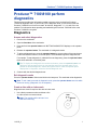
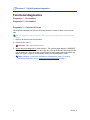
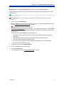
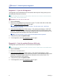
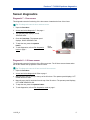
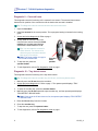
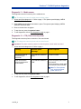
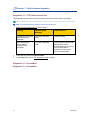
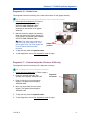
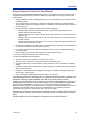
This manual provides the information needed to operate the Rimage Producer III, identify the autoloader parts, and align the printer. This manual provides the information needed to operate the Producer 7100 and the Producer 8100 autoloaders. These products are part of the Rimage Producer III family of products. The term ‘Producer III’ is used throughout this document to refer to the Producer 7100 or the Producer 8100. Producer 7100 ™ Producer 8100 ™ Perform diagnostics Corporate Headquarters: Rimage Corporation 7725 Washington Avenue South Minneapolis, MN 55439 USA 800 553 8312 (toll free US) Service: +1 952 946 0004 (International) Fax: +1 952 944 6956 European Headquarters: Rimage Europe GmbH Hans-Böckler-Straße 7 63128 Dietzenbach, Germany Tel: +49-(0) 6074-8521-0 Fax: +49-(0) 6074-8521-21 CD and DVD Recording Software Disclaimer This product, software, or documentation may be designed to assist you in reproducing material in which you own the copyright or have obtained permission to copy from the copyright owner. Unless you own the copyright or have permission to copy from the copyright owner, you may be violating copyright law and be subject to payment of damages and other remedies. If you are uncertain about your rights, you should contact your legal advisor. If you are neither in possession of the copyright nor have authorization from the owner of the copyright, unauthorized copying of CDs and DVDs violates national and international legislation and can result in severe penalties. Rimage Corporation reserves the right to make improvements to the equipment and software described in this document at any time without any prior notice. Rimage Corporation reserves the right to revise this publication and to make changes from time to time in the content hereof without obligation of Rimage Corporation to notify any person or organization of such revisions or changes. This document may contain links to web sites that were current at the time of publication, but may have moved or become inactive since. This document may contain links to sites on the Internet that are owned and operated by third parties. Rimage Corporation is not responsible for the content of any such third-party site. ©2006 Rimage Corporation Producer™ is a trademark of the Rimage ® Corporation. Dell is registered trademark of Dell ® Computer Corporation. FireWire is a registered trademark of Apple Computer, Inc. All other trademarks and registered trademarks are the property of their respective owners. Support information US, Asia/Pacific, Mexico/Latin America Europe Rimage Corporation 7725 Washington Avenue South Minneapolis, MN 55439 USA Attn: Rimage Services Rimage Europe GmbH Hans-Böckler-Straße 7 63128 Dietzenbach, Germany Service: FAX: +49-(0) 6074-8521-21 Tel: +49-(0) 6074-8521-0 Rimage Europe Technical Website North America: 800-553-8312 Asia/Pacific, Mexico/ Latin America: 952-946-0004 FAX: 952-946-6956 When you contact Rimage Services, please provide: http://www.rimage.de/support.html Select the appropriate Support link to learn more. If you cannot find a solution on our website, email Rimage Services, Europe at [email protected]. • Unit serial number and software version. • Functional and technical description of the problem. • Exact error message received. Learn more online At www.rimage.com/support.html, you can experience Rimage’s world-class Support and Services. 1. Select your product family. 2. Select your product. 3. Learn more on your product page. From your product page you can access: • Information about the latest software and firmware updates • Product specifications • Troubleshooting tips and FAQs • The latest documents • Printing tips • Current firmware and driver downloads Contents Contents Producer™ 7100\8100 perform diagnostics................................... 1 Diagnostics ......................................................................................................1 Access and select diagnostics .............................................................................. 1 Exit diagnostic mode ............................................................................................. 1 Create a disc with an index mark .......................................................................... 1 Functional diagnostics .....................................................................................2 Diagnostic 1 – Not enabled ................................................................................... 2 Diagnostic 2 – Not enabled ................................................................................... 2 Diagnostic 3 – Calibrate lift home.......................................................................... 2 Diagnostic 4 – Cycle media between the recorder and the printer........................ 3 Diagnostic 5 – Cycle the lift diagnostic.................................................................. 4 Diagnostic 6 – Cycle the mailslot (Producer 8100 only)........................................ 4 Sensor diagnostics ..........................................................................................5 Diagnostic 7 – Door sensor ................................................................................... 5 Diagnostic 8 – Lift home sensor ............................................................................ 5 Diagnostic 9 – Carousel home .............................................................................. 6 Diagnostic 10 – Tray detect sensor....................................................................... 6 Diagnostic 11 – Media sensor ............................................................................... 7 Diagnostic 12 – CTS (Clear to send) printer ......................................................... 7 Diagnostic 13 – CTS (Clear to send) host............................................................. 8 Diagnostic 14 – Not enabled ................................................................................. 8 Diagnostic 15 – Not enabled ................................................................................. 8 Diagnostic 16 – Rotate home ................................................................................ 9 Diagnostic 17 – External output bin (Producer 8100 only) .................................... 9 Diagnostic 18 – Diverter home position sensor (Producer 8100 only) ................ 10 Learn More ...................................................................................... 11 Technical support and product updates .............................................................. 11 Safety information ............................................................................................... 11 Safety testing....................................................................................................... 12 Rimage Producer III Limited One Year Warranty................................................ 13 112155_A i Producer™ 7100\8100 perform diagnostics . ii Producer™ 7100\8100 perform diagnostics Producer™ 7100\8100 perform diagnostics This document provides the information needed to access, select, and perform Producer 7100\8100 diagnostic tests. To perform any of the diagnostic tests, you must ensure that the Producer 7100\8100 is not in an error state. At this time, diagnostics 1, 2, 14, and 15 are not enabled. For information about operating and maintaining the Producer 7100\8100 refer to the Producer 7100\8100 user guide. Diagnostics Access and select diagnostics 1. Power on the autoloader. 2. Open the front door of the autoloader. 3. Press and hold the operator button until BUTTON DIAGNOSTICS displays on the operator panel. 4. Release the operator button. The autoloader is in diagnostic mode. 5. To select a diagnostic test, press the operator button the same number of times as the test number and hold the button in on the last press. The autoloader begins the diagnostic test. For example: To start diagnostic 3 (calibrate lift home diagnostic), press the operator button three times and hold it on the third press. # Tip: To display each diagnostic test number and name, press the operator button at a rate that is slow enough so that you can read the test on the operator panel. If you passed the desired diagnostic, release the operator button. After the operator panel displays the 01 diagnostic, select the desired diagnostic test. 6. Continue with the desired diagnostic test. Exit diagnostic mode Press the operator button 19 times and hold on the last press. The autoloader exits diagnostics. Note: To exit a test but remain in diagnostic mode, press the operator button one time while the test is running. (Diagnostic 3 is an exception). Create a disc with an index mark Diagnostic tests 4 and 5 require a disc with an index mark. 1. Use a black permanent marker and draw a line on a disc near the center as shown. Note: The mark should be at least 1 mm wide and 4 mm long. 112155_A 1 mm 4 mm 1 Producer™ 7100\8100 perform diagnostics Functional diagnostics Diagnostic 1 – Not enabled Diagnostic 2 – Not enabled Diagnostic 3 – Calibrate lift home This diagnostic calibrates the lift arm to accurately detect the number of discs in the carousel bins. # Tip: This diagnostic uses the carousel motor, lift motor, carousel sensor, and the lift home sensor. 1. Remove all discs from the carousel bins. 2. Place one disc in bin 1. - Important: Place only one disc in bin 1. 3. Access and select diagnostic 3. Refer to page 1. The operator panel displays, CALIBRATE DIAGNOSTIC. The lift arm moves to the supply bin, picks up the disc and then drops the disc into the supply bin. Then, the lift arm moves back to its home position above the printer tray. When this cycle is complete, the autoloader restarts and exits diagnostics mode. Note: Diagnostic 3 causes the autoloader to exit diagnostics mode. To continue performing diagnostics, refer to Access and select diagnostics on page 1. 2 112155_A Producer™ 7100\8100 perform diagnostics Diagnostic 4 – Cycle media between the recorder and the printer This diagnostic cycles a disc from an open recorder tray to the printer tray and returns it to the recorder tray. # Tip: This diagnostic uses the lift motor, printer, rotate motor, index sensor, media sensor, and the drawer sensor. - Important! Before you cycle media, ensure that the printer and recorders are properly aligned. 1. Open one of the recorder trays. 2. Place one disc with an index mark on the recorder tray. To create a disc with an index mark, refer to Create a disc with an index mark on page 1. - Important: Do not close the recorder tray. 3. Access and select diagnostic 4. Refer to page 1. The operator panel displays, CYCLE MEDIA cycle = 000000. The printer tray opens and closes. The lift arm moves to the recorder tray to sense the disc. The following sequence repeats until you stop the test, • The lift arm picks up the disc from the recorder tray and rotates the disc to locate the index mark. • After locating the index mark, the lift arm places the disc on the printer tray. • The printer tray clamps and unclamps the disc. • The lift arm picks up the disc from the printer tray and places it on the recorder tray. • The cycle count increments by one. 4. To stop the test, press the operator button. 5. Remove the disc from the recorder tray. 6. Close the recorder tray. 7. To exit diagnostics, refer to Exit diagnostics mode on page 1. 112155_A 3 Producer™ 7100\8100 perform diagnostics Diagnostic 5 – Cycle the lift diagnostic This diagnostic cycles media between the carousel bins and the printer. During each cycle, the test locates the index mark on the disc. # Tip: This diagnostic uses the lift motor, printer, rotate motor, the carousel, carousel sensors, index sensor, and the media sensor. - Important: Use a disc with an index mark. 1. Open the front door. 2. Place one or more discs with an index mark in any bin. To create a disc with an index mark, refer to Create a disc with an index mark on page 1. Note: The lift arm starts to pick discs from bin 1. If a disc is not in bin 1, the lift arm proceeds to the next bin. 3. Access and select diagnostic 5. Refer to page 1. The operator panel displays, CYCLE LIFT cycle = 00000. The lift arm moves down to the carousel and picks up the disc with an index mark on it. The printer tray opens. The lift arm releases the disc on top of the printer tray. The lift arm picks up the disc and drops it into a bin in the carousel. Note: The test continues to cycle media until the operator button is pressed. 4. To stop the test, press the operator button. 5. To exit diagnostics, refer to Exit diagnostics mode on page 1. Diagnostic 6 – Cycle the mailslot (Producer 8100 only) This diagnostic cycles a disc from bin 1 of the carousel to the output bin. # Tip: This diagnostic uses the lift motor, carousel, diverter, mailslot sensor, and media sensor. 1. Open the front door. 2. Place one or more discs in bin 1. 3. Access and select diagnostic 6. Refer to page 1. The operator panel displays, CYCLE MAILSLOT DIAGNOSTIC. The lift arm picks a disc from bin 1 of the carousel and moves past the diverter. The diverter drops and the lift arm releases the disc onto the diverter. The diverter moves the disc to the output bin. 4. To stop the test, press the operator button. 5. To exit diagnostics, refer to Exit diagnostics mode on page 1. 4 112155_A Producer™ 7100\8100 perform diagnostics Sensor diagnostics Diagnostic 7 – Door sensor This diagnostic tests the functioning of the door sensor located at the front of the frame. # Tip: This diagnostic uses the door and door sensor. 1. Open the front door. 2. Access and select diagnostic 7. See page 1. 3. The operator panel displays, DOOR SENSOR HIGH. 4. Close the front door. The operator panel displays, DOOR SENSOR LOW. 5. To stop the test, press the operator button. 6. To exit diagnostics, refer to Exit diagnostics mode on page 1. Door sensor Diagnostic 8 – Lift home sensor This diagnostic tests the functioning of the lift home sensor. The lift home sensor detects when the lift arm reaches the top position of the lift column. # Tip: This diagnostic uses the lift arm and the lift home sensor. 1. Open the front door. 2. Access and select diagnostic 8. Refer to page 1. 3. Manually move the lift arm up to the top of the lift column. The operator panel displays, LIFT HOME SENSOR HIGH. 4. Manually move the lift arm down from the top of the lift column. The operator panel displays, LIFT HOME SENSOR LOW. 5. To stop the test, press the operator button. 6. To exit diagnostics, refer to Exit diagnostics mode on page 1. 112155_A 5 Producer™ 7100\8100 perform diagnostics Diagnostic 9 – Carousel home This diagnostic tests the functioning of the carousel home sensor. The carousel home sensor detects the bin position of the carousel as well as whether the carousel is installed. # Tip: This diagnostic uses the carousel and the carousel home sensor. 1. Open the front door. 2. Install the carousel in the correct position. The top support bearing is inserted in the bearing guide. 3. Access and select diagnostic 9. Refer to page 1. 4. Slowly rotate the carousel. When the carousel home sensor detects the home position, the operator panel displays, CAROUSEL HOME SENSOR LOW. # Tip: You can rotate the carousel in either direction. The sensor must detect the gap in the metal carousel base once per revolution. Note: The home position is a gap in the metal carousel base. 5. To stop the test, press the operator button. Carousel home position 6. To exit diagnostics, refer to Exit diagnostics mode on page 1. Diagnostic 10 – Tray detect sensor This diagnostic tests the functioning of the tray detect sensor. # Tip: This diagnostic uses the recorder tray, the lift arm, and the tray detect sensor. 1. Manually move the lift arm above the recorders. 2. Access and select diagnostic 10. Refer to page 1. The operator panel displays, TRAY DETECT SENSOR LOW. 3. To open the recorder tray, press the recorder button. 4. Manually move the lift arm toward the open recorder tray, until the operator panel displays, TRAY DETECT SENSOR HIGH. Note: If you move the lift arm down too far, the operator panel displays TRAY DETECT SENSOR LOW. 5. Raise the lift arm away from the recorder. 6. Close the recorder tray. 7. To stop the test, press the operator button. 8. To exit diagnostics, refer to Exit diagnostics mode on page 1. 6 112155_A Producer™ 7100\8100 perform diagnostics Diagnostic 11 – Media sensor This diagnostic tests the functioning of the media sensor. # Tip: This diagnostic uses the media sensor and the gripper. 1. Access and select diagnostic 11. Refer to page 1. The operator panel displays, MEDIA GRIPPER SENSOR LOW. 2. Press a disc onto the gripper and hold it in place. The operator panel displays, MEDIA GRIPPER SENSOR HIGH. 3. Remove the disc from the gripper. 4. To stop the test, press the operator button. 5. To exit diagnostics, refer to Exit diagnostics mode on page 1. Diagnostic 12 – CTS (Clear to send) printer This diagnostic tests the printer connection to the control board. # Tip: This diagnostic uses the printer and the control board. - Important: The printer must be powered on with the printer control cable connected. 1. Access and select diagnostic 12. Refer to page 1. Sensing Operator panel message Action required Senses the printer is connected to the autoloader CTS PRINTER SENSOR HIGH No action needed. Does not sense the printer is connected to the autoloader CTS PRINTER SENSOR LOW Ensure the printer power cable is connected. Ensure the printer control cable is connected to the autoloader. Note: For Prism printers only, ensure the printer power switch is on. 2. To stop the test, press the operator button. 3. To exit diagnostics, refer to Exit diagnostics mode on page 1. 112155_A 7 Producer™ 7100\8100 perform diagnostics Diagnostic 13 – CTS (Clear to send) host This diagnostic tests the cable connection between the control center and the autoloader. # Tip: This diagnostic uses the USB cable connection, the control center, and the autoloader. Note: The Production Server must be running during this test. 1. Access and select diagnostic 13. Refer to page 1. Sensing Operator panel message Action required Senses the control center is connected to the autoloader CTS HOST SENSOR HIGH No action needed. Does not sense the control center is connected to the autoloader CTS HOST SENSOR LOW Ensure Production Server was initiated and is running. If Production Server is running, verify the USB cable is connected from the control center to the autoloader. 2. To stop the test, press the operator button. 3. To exit diagnostics, refer to Exit diagnostics mode on page 1. Diagnostic 14 – Not enabled Diagnostic 15 – Not enabled 8 112155_A Producer™ 7100\8100 perform diagnostics Diagnostic 16 – Rotate home This diagnostic tests the functioning of the rotate home sensor on the gripper assembly. # Tip: This diagnostic uses the gripper assembly and the rotate home sensor. 1. Access and select diagnostic 16. Refer to page 1. The operator panel displays, ROTATE HOME SENSOR LOW or ROTATE HOME SENSOR HIGH depending on the position of the gripper assembly. 2. Manually rotate the gripper hub assembly. When the rotate home sensor detects the home position, the operator panel displays, ROTATE HOME SENSOR HIGH. Note: The rotate home position is a gap in the ring of the gripper hub. There are two gaps in the ring of the gripper hub. Home is detected two times each revolution. Rotate home position 3. To stop the test, press the operator button. 4. To exit diagnostics, refer to Exit diagnostics mode on page 1. Diagnostic 17 – External output bin (Producer 8100 only) This diagnostic tests the functioning of the dispenser full sensor. # Tip: This diagnostic uses the dispenser full sensor. 1. Access and select diagnostic 17. Refer to page 1. 2. Empty the external output bin. The operator panel displays, SENSOR LOW. Dispenser full sensor 3. Place your finger in front of the sensor window. The operator panel displays, SENSOR HIGH. 4. Move your finger away from the sensor window. The operator panel displays, SENSOR LOW. 5. To stop the test, press the operator button. 6. To exit diagnostics, refer to Exit diagnostics mode on page 1. 112155_A 9 Producer™ 7100\8100 perform diagnostics Diagnostic 18 – Diverter home position sensor (Producer 8100 only) This diagnostic tests the functioning of the diverter home position sensor. # Tip: This diagnostic uses the diverter home position sensor. 1. Access and select diagnostic 18. Refer to page 1. 2. With the diverter tray in the vertical position, the operator panel displays, SENSOR HIGH. Move the diverter tray down. The operator panel displays, SENSOR LOW. 3. To stop the test, press the operator button. 4. To exit diagnostics, refer to Exit diagnostics mode on page 1. 10 112155_A Learn More Learn More Technical support and product updates Support for the Producer III is available through your authorized reseller. - Important! Register your Producer III online or complete and return the registration card so Rimage can notify you of upgrades as they become available. Safety information This manual and the indications on the product allow proper and safe operation. The indication marks below help protect you and other persons from injury, and equipment from damage. - Important! Any equipment that has certain components using AC line voltage, or in some cases low DC voltages, such as power switches, power supplies, fuses, fans, non-stepper motors, must be replaced with Rimage–approved components to maintain the safety approval issued by UL. n Warning! According to ANSI (American National Standards Institute) standards, a warning is used to indicate situations that could result in bodily injury to personnel operating or maintaining the equipment. p Caution: Indicates that failure to observe this guideline could result in loss or damage to the equipment, product, software, or data. Safety precautions To ensure safety, please read the precautions in the user guide and familiarize yourself with their meaning before using the equipment. p Caution: For continued protection against risk of fire, replace the fuse only with the same type and rating. An authorized technician should perform all service procedures. p Caution: Use only the supplied AC power cord, or use a safety agency approved power cord. For applications outside North America, refer to the nearest Rimage office for assistance in selecting a locally approved power cord. p Caution: Use of controls or adjustments or performance of procedures other than those specified herein may result in hazardous radiant exposure. n Warning! The laser beam used by the CD recorder is a Class 1 laser. Do not attempt to open the recorder. An authorized technician should perform all service procedures. n Warning! The laser beam used by the DVD-R recorder is a Class 2 laser and can be harmful to the eyes. Do not attempt to open the recorder. An authorized technician should perform all service procedures. 112155_A 11 Producer™ 7100\8100 perform diagnostics Safety testing Product name: Producer 7100, Producer 8100 Model: Producer 7100: RAS19 Producer 8100: RAS18 Notice for USA NOTE: This equipment has been tested and found to comply with the limits for a Class A digital device, pursuant to part 15 of the FCC Rules. These limits are designed to provide reasonable protection against harmful interference when equipment is operated in a commercial environment. This equipment generates, uses, and can radiate radio frequency energy and, if not installed and used in accordance with the instruction manual, may cause harmful interference to radio communications. Operation of this equipment in a residential area is likely to cause harmful interference, in which case the user will be required to correct the interference at their expense. This product complies with UL 60950-1 1st edition. Notice for Canada C This Class A digital apparatus complies with Canadian ICES-003Issue 3:1997. Cet appareil numerigue de la classe A est conforme a la norme NMB-003 du Canade. This product complies with CAN/CSA-C22.2 No. 60950-1-03 1st edition. Notice for Europe This product is in conformity with the EMC Directive (89/336/EEC) and the Low-Voltage Directive (73/23/EEC) through compliance with the following European standards: EN 60950:2000, EN 55022:1998 + A1: 2000 & A2: 2003, EN 55024:1998 & A1: 2001 & A2: 2003, EN 61000-3-2:2000, EN 61000-3-3:1995 & A1: 2001. The CE mark has been affixed in accordance with the CE Marking Directive 93/68/EEC. Notice for Japan VCCI This product complies with VCCI V.3/2005.04 12 Notice for Australia CTICK This product complies with AS/NZS CISPR22:2004 112155_A Learn More Rimage Producer III Limited One Year Warranty Rimage warrants, to the original end user only, that all non-consumable parts of the Producer III family of automated products will be free from defects in material or workmanship for 12 months, according to the following terms: • Rimage will replace or repair, at Rimage's discretion, any non-consumable parts found defective within the Warranty period. • The 12 month warranty period begins on the date of valid system activation on the Rimage website. Where system activation on the Rimage website is not available, the warranty start date is the date the product ships to you. • Factory depot repair: Equipment requiring service should be shipped to: Rimage in Minnesota from a location within the US or Canada with a typical response of 15 business days from the date of receipt. Rimage in Germany from a location in Europe with a typical response of 15 business days from the date of receipt. Rimage in Japan from a location in Asia / Pacific with a typical response of 15 business days from the date of receipt. Rimage in Minnesota from a location that is not in the US or Canada with a typical response of 25 business days from the date of receipt. • On-site repair is available for an additional fee. Advanced Exchange replacement or other Maintenance Contracts are available to enhance your warranty service. • For systems with valid end user activations, Rimage will provide one year of software updates during the warranty period. • Rimage will pay ground service freight charges for components shipped to you. The use of non-Rimage certified parts may void this warranty. This Warranty does not include the following: • Work done at the customer's location, or customer's loss of data. • Shipment costs for equipment or components returned to the Rimage factory. • Equipment malfunctions as a result of repairs made by persons who are not authorized or certified by Rimage. • Equipment or parts that were tampered with, misused, neglected, or modified in any respect without the written consent of Rimage. • Equipment or parts that have been damaged due to shipping or accidents, or damaged by lightning, storms, water, or power surges. • Printer consumables including ribbons, retransfer ribbons, or print head. YOU MAY NOT ASSIGN THIS WARRANTY WITHOUT RIMAGE'S WRITTEN CONSENT. RIMAGE IS THE INTENDED BENEFICIARY OF THIS WARRANTY; IF THERE IS ANY INCONSISTENCY BETWEEN THIS WARRANTY AND ANY OTHER AGREEMENT INCLUDED WITH OR RELATING TO RIMAGE PRODUCTS, THIS WARRANTY SHALL GOVERN. IF ANY TERM OF THIS WARRANTY IS ILLEGAL OR UNENFORCEABLE, THE LEGALITY AND ENFORCEABILITY OF THE REMAINING PROVISIONS ARE NOT AFFECTED OR IMPAIRED. This Warranty is to be interpreted under the laws of the State of Minnesota, without giving effect to conflict of law rules. The provisions of the United Nations Convention on Contracts for the International Sale of Goods or the United Nations on the Limitation Period in the International Sale of Goods, as amended from time to time, shall not apply. Rimage must receive written notice of any claimed defect or failure to perform within five (5) days after such failure or defect is first observed. For warranty service, call Rimage US at +952-9460004, Rimage Asia/Pacific at +81-3-5283-8465, or Rimage Europe at +49-0-6074-8521-0. 112155_A 13