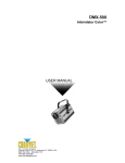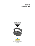
1
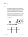
ST-200X
Techno Strobe™ 200X
USER MANUAL
Chauvet, 3000 N 29th Ct, Hollywood, FL 33020 U.S.A
(800) 762-1084 – (954) 929-1115
FAX (954) 929-5560
www.chauvetlighting.com
TABLE OF CONTENT
BEFORE YOU BEGIN........................................................................................................................................................... 3
WHAT IS INCLUDED ................................................................................................................................................................................ 3
UNPACKING INSTRUCTIONS .................................................................................................................................................................... 3
SAFETY INSTRUCTIONS .......................................................................................................................................................................... 3
INTRODUCTION ................................................................................................................................................................... 4
FEATURES ............................................................................................................................................................................................ 4
DMX CHANNEL SUMMARY ..................................................................................................................................................................... 4
PRODUCT OVERVIEW ............................................................................................................................................................................ 4
SETUP ................................................................................................................................................................................... 5
LAMP ................................................................................................................................................................................................... 5
Lamp installation ................................................................................................................................................................................................ 5
MOUNTING ........................................................................................................................................................................................... 6
Orientation .......................................................................................................................................................................................................... 6
Rigging ............................................................................................................................................................................................................... 6
Wall Mount.......................................................................................................................................................................................................... 6
USING A COLOR GEL ............................................................................................................................................................................. 6
OPERATING INSTRUCTIONS.............................................................................................................................................. 7
MENU NAVIGATION ................................................................................................................................................................................ 7
OPERATING MODES............................................................................................................................................................................... 8
Stand Alone ........................................................................................................................................................................................................ 8
Master/Slave....................................................................................................................................................................................................... 8
DMX Mode.......................................................................................................................................................................................................... 8
MENU FUNCTIONS ................................................................................................................................................................................. 8
DMX-512 addressing {Addr} ......................................................................................................................................... 8
Setting the starting address ............................................................................................................................................................................... 9
Master/Slave settings {SHNd} ¾ {4LSH} ¾ {8LSH} ...................................................................................................... 9
Selecting Between 4-Light & 8-Light Show........................................................................................................................................................ 9
Addressing Slave Units .................................................................................................................................................................................... 10
Segment Display Configurations {IdSP} ..................................................................................................................... 10
Display Inverse {IdSP}...................................................................................................................................................................................... 10
Fixture Test and Service Functions {teSt}, {FhrS}, {rSet} ........................................................................................... 11
Fixture Self-Test {teSt} ..................................................................................................................................................................................... 11
Fixture Reset {rSet} .......................................................................................................................................................................................... 11
Fixture Hours {FhrS}......................................................................................................................................................................................... 11
CA-8 & CA-8F Easy Controller (Optional) .................................................................................................................. 12
APPENDIX........................................................................................................................................................................... 13
DMX PRIMER ..................................................................................................................................................................................... 13
Fixture Linking .................................................................................................................................................................................................. 13
DMX CHANNEL VALUES ...................................................................................................................................................................... 14
GENERAL MAINTENANCE ..................................................................................................................................................................... 14
RETURNS PROCEDURE ........................................................................................................................................................................ 15
CLAIMS .............................................................................................................................................................................................. 15
GENERAL TROUBLESHOOTING .............................................................................................................................................................. 15
TECHNICAL SPECIFICATIONS ................................................................................................................................................................ 17
ST-200X User Manual
2
Revision: 2004-11-02/11:00
BEFORE YOU BEGIN
What is included
¾
¾
¾
¾
ST-200X
Power cord with plug
200w Xenon lamp (Installed)
Warranty Card
Unpacking Instructions
Immediately upon receiving a fixture, carefully unpack the carton, check the contents to ensure that
all parts are present, and have been received in good condition. Notify the shipper immediately and
retain packing material for inspection if any parts appear damaged from shipping or the carton itself
shows signs of mishandling. Save the carton and all packing materials. In the event that a fixture
must be returned to the factory, it is important that the fixture be returned in the original factory box
and packing.
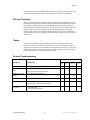
Safety Instructions
Please read these instructions carefully, which
includes important information about the installation,
usage and maintenance?
•
•
•
•
•
•
•
•
•
•
•
•
•
Caution!
Please keep this User Guide for future consultation. If you sell the unit to another user, be sure that
they also receive this instruction booklet.
Always make sure that you are connecting to the proper voltage and that the line voltage you are
connecting to is not higher than that stated on decal or rear panel of the fixture.
This product is intended for indoor use only!
To prevent risk of fire or shock, do not expose fixture to rain or moisture. Make sure there are no
flammable materials close to the unit while operating.
The unit must be installed in a location with adequate ventilation, at least 50cm from adjacent
surfaces. Be sure that no ventilation slots are blocked.
Always disconnect from power source before servicing or replacing lamp or fuse and be sure to
replace with same lamp source.
Secure fixture to fastening device using a safety chain. Never carry the fixture solely by its head. Use
its carrying handles.
Maximum ambient temperature is Ta: 40°. Do not operate fixture at temperatures higher than this.
In the event of serious operating problem, stop using the unit immediately. Never try to repair the unit
by yourself. Repairs carried out by unskilled people can lead to damage or malfunction. Please
contact the nearest authorized technical assistance center. Always use the same type spare parts.
Don’t connect the device to a dimmer pack.
Make sure power cord is never crimped or damaged.
Never disconnect power cord by pulling or tugging on the cord.
Avoid direct eye exposure to lamp.
There are no user serviceable parts inside the unit. Do not any repairs yourself. In
the unlikely event your unit may require service, please contact CHAUVET.
ST-200X User Manual
3
Revision: 2004-11-02/11:00
INTRODUCTION
Features
•
•
•
•
•
•
DMX control
strobe speed control
intensity control
wall-mountable fixture
LED control panel display
Master/Slave mode
DMX Channel Summary
Channel
Function
1
Strobe speed
2
Intensity
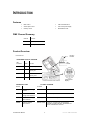
Product Overview
Product Overview
Hanging
bracket
LED SEGMENT DISPLAY OVERVIEW
Gel
Holder
LED
Indicators
Status
Function
DMX
On
DMX input is present
MASTER
On
Unit is in the Master
operating ode
Slave
On
Unit is in the Slave
operating mode
Sound
Flashing
Sound Active mode is on
I/O Panel located on bottom of fixture
SEGMENT BUTTONS
Buttons
LED Segment
Display
I/O PANEL OVERVIEW
I/O Panel
MENU
Toggles programming
functions
DMX Out & In
DMX-512 connectors
DOWN
Steps backward
through menu functions
MIC
Built in microphone
UP
Steps forward through
menu functions
Sensitivity POT
Sets audio sensitivity
ENTER
Confirms selected
menu function
Remote control
Accepts ¼” connector from the “CA-8 Easy
Controller” providing Stand By, Strobe/Next and
Show1 1/Slow/Show 2 functions.
ST-200X User Manual
4
Revision: 2004-11-02/11:00
SETUP
Lamp
The xenon 200 watt lamp comes pre-installed from the factory.
Warning!
When replacing the lamp, please wait 15 minutes after powering down to allow the
unit to cool down! Always disconnect from main power prior to lamp replacement.
Do not touch the envelope (glass area) of the bulb with bare hands. If this happens, clean the lamp
with alcohol and wipe it with a lint free cloth before installation.
LA M P IN STA LLA T ION
1)
Unscrew the three most left and right screws on the back of the ST-200X and lift the front cover
carefully. The segment display can remain attached to the PCB during lamp replacement.
2)
Unscrew the three lamp wires from their respective terminals on the PCB as illustrated in Figure
3. You may need to clip the tie-wraps that restrain the loose wires to the screw posts on the PCB
in order to free the lamp.
3)
Slide lamp socket out of the thin metal plate one end at a time.
4)
Replace strobe with new lamp and re-fasten wires to the terminals. (CHAUVET lamp model #
BL-200ST)
Top view
ST-200X Lamp Installation
Lamp side with 2 wires;
Lamp side with 1
wire molded into
ceramic base
gets fastened to
terminal labeled
J3.
J3
J4
1.
Wire molded into
ceramic base is
fastened to
terminal labeled J4
2.
Wire coiled around
the envelope of the
bulb gets fastened
to terminal labeled
J5.
J5
5)
If you are replacing the lamp, you may want to log the fixture hours in order to track the lamps
use. Navigate to the {FhrS} on the menu display to obtain this information.
6)
Replace front cover and screws.
ST-200X User Manual
5
Revision: 2004-11-02/11:00
Setup
Mounting
ORIENTATION
This fixture may be mounted in any position provided there is adequate room for ventilation.
R IG G IN G
Figure 1 - Hanging Bracket
It is important never to obstruct the fan or vents pathway. Mount the
fixture using, a suitable “C” or “O” type clamp. Adjust the angle of the
fixture by loosening both knobs and tilting the fixture. After finding
the desired position, retighten both knobs.
•
•
•
When selecting installation location, take into consideration lamp
replacement access and routine maintenance.
Safety cables should always be used.
Never mount in places where the fixture will be exposed to rain, high
humidity, extreme temperature changes or restricted ventilation.
Note!
Clamp is sold separately.
W A L L M OU N T
The ST-200X is light enough that it can be hung from a wall by its wall-mount hole located centered
near the top of the back of the fixture. Side ventilation panels allow breathing room so it is important
to allow at least 12 inches of unencumbered space on both sides.
Using a Color Gel
The ST-200X is equipped with a detachable clear front cover that doubles as a gel holder as
illustrated below.
1)
Open the clear lamp cover by removing the thumbscrew.
2)
Cut a piece of gel filter to match the size of the cover or slightly
larger. The size of the gel used in the illustration was a 6.5” by
6.5”.
3)
Lay the gel over the opening, close cover and replace the
thumbscrew securely.
ST-200X User Manual
6
Revision: 2004-11-02/11:00
OPERATING INSTRUCTIONS
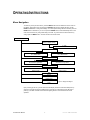
Menu Navigation
To select any of the pre-set functions, press the MENU button until the desired function is shown on
the display. Select the function by pressing the ENTER button and the display will blink. Use the
DOWN and UP button to change the settings. Once the required setting has been selected, press the
ENTER button to activate it. If you don not press the ENTER button, it will automatically return to the
main functions without any change after idling 8 seconds. To go back to the functions without any
change press the MENU button. The main functions are shown below:
MENU
Addr
DMX-512 Address Setting
1 ~ 512
NASt
no
YeS
No to Master Mode
Yes to Master Mode
SHNd
8LSH
4LSH
Show Mode “8 Light Show”
Show Mode “4 Light Show”
IdSP
IdSP
dSPI
Display Inverse
Display Normal
test
Self test
FhrS
Fixture hours
rSeT
Reset
Figure 2 - Display Panel Diagram
Upon powering up the unit, you will notice that it will display a fixture ID. After this initial power-up
sequence, if the fixture receives no DMX signal, it will enter into a stand alone mode. Be sure to
power up your DMX controller device before the lighting fixture to avoid unwanted auto mode
operation.
ST-200X User Manual
7
Revision: 2004-11-02/11:00
Operating Instructions
Operating Modes
•
•
•
A stand-alone mode will listen to sound and run through its diverse range of built in programs.
Master/Slave mode will allow the command of up to as many units you want in a synchronized light
show to the sound.
DMX control mode will provide the greatest flexibility and creativity. Each fixture trait can be controlled
individually using any universal DMX-512 controller.
STAND ALONE
The Stand Alone mode is activated automatically when the fixture is absent of DMX signal or a
controller is not connected. All models will run through their built in programs as they listen to the
sound.
MASTER /SLAVE
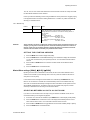
The Master/Slave mode will allow you to link up to as many units you want in a daisy chain fashion. In
this mode, the first unit in the daisy chain will automatically command all other units following. A CA-8
and CA-8F Easy controller connected to the first unit in the chain will allow enhanced simple control
functions. Master/Slave operation does not require any menu or setting selections. Simply connect
each fixture in a daisy like fashion using qualified 3 pin DMX cables as described below.
1)
Connect the (male) 3 pin connector side of the DMX cable to the output (female) 3 pin connector
of the first fixture.
2)
Connect the end of the cable coming from the first fixture which will have a (female) 3 pin
connector to the input connector of the next fixture consisting of a (male) 3 pin connector. Then,
proceed to connect from the output as stated above to the input of the following fixture and so on
as illustrated below.
Daisy Chain Connection
Optional Controller
D MX MODE
Operating in a DMX Control mode environment gives the user the greatest flexibility when it comes to
customizing or creating a show. In this mode you will be able to control each individual trait of the
fixture independently.
Menu Functions
DMX-512 addressing {Addr}
This mode enables the use of a universal DMX controller device. Each fixture requires a "start
address" from 1 to 511. A fixture requiring one or more channels for control begins to read the data
on the channel indicated by the start address. For example, a fixture that occupies or uses 6 channels
of DMX and was addressed to start on DMX channel 100, would read data from channels: 100, 101,
ST-200X User Manual
8
Revision: 2004-11-02/11:00
Operating Instructions
102, 103, 104, and 105. Choose start addresses so that the channels used do not overlap and notate
the start address selected for future reference.
If this is your first time addressing a fixture using the DMX-512 control protocol than I suggest jumping
to the Appendix Section and read the heading “DMX Primer”. It contains very useful information that
will help you understand its use.
Table 1 - DMX Addressing
Caution!
Fixture
DMX Channels
Notes
ST-200X
2
When calculating the next starting address for a particular fixture,
simply add the number of channels used by the last fixture to the
starting address of the last fixture. The result is the starting address of
the next fixture.
Example:
ST-200X 2Channels,
set to Addr 001
Add 2 to the previous start address 002 +
Next Fixture,
set to Addr 003 Total
Add 2 to the previous start address 002 +
Next Fixture,
set to Addr 005 Total
Some controllers are factory configured to control a specific range of channels per fixture. For
example, you may have a controller pre-set to control 10 channels per fixture for a total of 12
fixtures. In this case you would be required to separate all fixtures in 10 channel increments
instead of the true number of channels your particular fixture utilizes.
SETTING TH E STAR TING ADDRESS
1)
Press the MENU button until the display reads {Addr}.
2)
Press the ENTER button to select DMX addressing. Once selected the display will read either a
1 or any other number that may have previously been set. You must make a selection within 6
seconds.
3)
Press the UP and DOWN buttons to increase or decrease values until the desired value is
achieved.
4)
Press the ENTER button to activate selection.
Master/Slave settings {SHNd} ¾ {4LSH} ¾ {8LSH}
By linking the units under a master/slave control mode, the first unit can direct additional units to
create a sound activated, synchronized light show. This is very useful for mobile DJs who want to
setup and run a show quickly.
In this mode the fixture is assigned a master status and is indicated by the MASTER LED. If the
fixture is not connected to a controller then it will automatically enter a sound activated state. Any
other units connected will automatically be assigned to Slave mode status and will operate in unison
with the Master designated unit. To make the most of the 4 and 8-light show programs, it will be
necessary to address the units according to the instructions below.
S E L ECT IN G B E TWE EN 4 - L IGH T & 8- L IGHT SH OW
If you have 8 or more strobes and are currently running the strobes in the Master mode, then we
recommend switching to the 8-light show playback.
1)
On the first unit in the chain set to Master, tap the MENU button until the display reads {SHNd}.
2)
Press the ENTER button to select this function. The display will immediately read the current
show mode the device is set to. You must make a selection within 6 seconds.
3)
Press the UP and DOWN buttons to toggle between the two shows available {4LSH} or {8LSH}.
4)
Press the ENTER button to activate selection.
ST-200X User Manual
9
Revision: 2004-11-02/11:00
Operating Instructions
ADDR ESSING SLAVE UN IT S
To make the most of the 4 and 8-light show programs, it will be necessary to address the units
according to the table illustrated below. The process for addressing slave units is the same as DMX
addressing.
1)
Press the MENU button until the display reads {Addr}.
2)
Press the ENTER button to select DMX addressing. Once selected the display will read either a
1 or any other number that may have previously been set. You must make a selection within 6
seconds.
3)
Press the UP and DOWN buttons to increase or decrease values until the desired value is
achieved.
4)
Press the ENTER button to activate selection.
Table 2 - 4-Light Show Addressing
4-Pattern
Show
Activity
Fixture Address {Addr}
SH-0
SH-1
SH-2
SH-3
SH-4
SH-5
SH-6
SH-7
SH-8
SH-9
SH-A
SH-B
1234 Full On
1-2-3-4
4-3-2-1
1-2-3-4-3-2
12-34
24-13
23-14
1-12-123-1234-123-12-1-stop
4-43-432-4321-432-43-4-stop
1-2-1-2-3-4-3-4
4-1-4-1-2-3-2-3
3-1-3-1-2-4-2-4
Master
Slave 1
Slave 2
Slave 3
8-Pattern
Show
Activity
Fixture Address {Addr}
SH-0
SH-1
SH-2
SH-3
SH-4
SH-5
SH-6
SH-7
SH-8
SH-9
SH-A
SH-B
12345678 Full On
1-2-3-4-5-6-7-8
8-7-6-5-4-3-2-1
81-72-63-54-63-72-81
15-26-37-48
84-73-62-51
1357-2468
1234-5678
1256-3478
12-23-34-45-56-67-78-81
87-76-65-54-43-32-21-18
54-63-72-81
Master
Slave 1
Slave 2
Slave 3
Slave 4
Slave 5
Slave 6
Slave 7
=
=
=
=
001
003
005
007
Table 3 - 8-Light Show Addressing
=
=
=
=
=
=
=
=
001
003
005
007
009
011
013
015
Segment Display Configurations {IdSP}
The display can be inverted making it easier to read the menu depending on the orientation of your
fixture.
D I S PL A Y IN V ER SE { Id S P }
1)
ST-200X User Manual
Tap the MENU button until the display reads {IdSP}.
10
Revision: 2004-11-02/11:00
Operating Instructions
2)
Unlike in other instructions, pressing the ENTER button will toggle between { IdSP} for normal
and {dSPI} for reversed.
3)
Press the MENU button to confirm or leave alone for 8 seconds.
Fixture Test and Service Functions {teSt}, {FhrS}, {rSet}
F I X T URE SEL F - TE S T { t e St }
The test sequence will run through all of the projection capabilities of each individual fixture, including
gobo and color effects.
1)
Tap the MENU button until the display reads {teSt}.
2)
Press ENTER and the fixture will immediately begin to play back a test sequence. Observe
tentatively for any abnormalities.
3)
Press the MENU button to leave this mode.
F I X T U R E R E S ET { r Se t }
This function will re-initialize the fixture by returning all motors to its startup positions or otherwise
known as (home position).
1)
Tap the MENU button until the display reads {rSet} and press ENTER.
FIXTUR E HOUR S {FhrS}
The (fixture hours) readout displays the number of hours the fixture has been in use. It is not
uncommon to find new fixtures with a few logged hours. This means the fixture was thoroughly tested
prior to delivery.
1)
Tap the MENU button until the display reads {FhrS}.
2)
Press ENTER to view the total working hours.
3)
You can leave alone and the display will return to the regular menu or press MENU button to
return to main menu.
ST-200X User Manual
11
Revision: 2004-11-02/11:00
Operating Instructions
CA-8 & CA-8F Easy Controller (Optional)
The CA-8 Easy Controller is used only in master/slave mode. Connect the controller to the 1/4”
microphone plug in the first unit. The table below describes the different preset shows the CA-8
Controller can command.
CA-8 BUTTONS
Stand By
Mode Button
Function button
Blackout
Audio
(LED off)
Press function and all units will
strobe quickly.
Figure 3 - CA-8 Easy Controller &
the CA-8F Foot Controller
(Audio triggered)
Manual
(LED on)
Steps to the next preset pattern.
Auto
(LED blinks)
Tap to select from 12 patterns
with preset speeds.
(Audio triggered)
Hold for 3 seconds to select 1 of
3 brightness levels.
Note! You must reselect the desired pattern
after setting a brightness level. Pressing the
Function key in this mode will automatically
step to the next pattern regardless of how
long you hold the key.
ST-200X User Manual
12
Revision: 2004-11-02/11:00
APPENDIX
DMX Primer
There are 512 channels in a DMX-512 connection. Channels may be assigned in any manner. A
fixture capable of receiving DMX-512 will require one or a number of sequential channels. The user
must assign a starting address on the fixture that indicates the first channel reserved in the controller.
There are many different types of DMX controllable fixtures and they all may vary in the total number
of channels required. Choosing a start address should be planned in advance. Channels should
never overlap. If they do, this will result in erratic operation of the fixtures whose starting address is
set incorrectly. You can however, control multiple fixtures of the same type using the same starting
address as long as the intended result is that of unison movement or operation. In other words, the
fixtures will be slaved together and all respond exactly the same.
DMX fixtures are designed to receive data through a serial Daisy Chain. A Daisy Chain connection is
where the DATA OUT of one fixture connects to the DATA IN of the next fixture. The order in which
the fixtures are connected is not important and has no effect on how a controller communicates to
each fixture. Use an order that provides for the easiest and most direct cabling. Connect fixtures
using shielded two conductor twisted pair cable with three pin XLR male to female connectors. The
shield connection is pin 1, while pin 2 is Data Negative (S-) and pin 3 is Data positive (S+). CHAUVET
carries 3-pin XLR DMX compliant cables, DMX-10 (33’), DMX-4.5 (15’) and DMX-1.5 (5’)
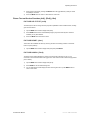
F I X T URE L I NKING
Figure 4 - DMX connector configuration
1
3
2
COMMON
INPUT
Note!
1
3
2
1
3
2
DMX +
Resistance 120
ohm 1/4w between
pin 2 (DMX -) and
pin 3 (DMX +) of
the last fixture.
OUTPUT
DMX -
Termination reduces signal errors and to
avoid signal transmission problems and
interference, it is always advisable to connect
a DMX signal terminator.
If you use a controller with a 5 pin DMX output connector, you will need to use a 5
pin to 3 pin adapter. Chauvet Model No: DMX5M.
The chart below details a proper cable conversion:
3 Pin to 5 Pin Conversion Chart
Conductor
3 Pin Female (output)
5 Pin Male (Input)
Ground/Shield
Pin 1
Pin 1
Data ( - )signal
Pin 2
Pin 2
Data ( + ) signal
Pin 3
Pin 3
Do not use
Do not use
Do not use
Do not use
ST-200X User Manual
13
Revision: 2004-11-02/11:00
Appendix
DMX Channel Values
Channel
Value
Function
1
000 Ù 015
016 Ù 031
032 Ù 047
048 Ù 063
064 Ù 079
080 Ù 095
096 Ù 110
111 Ù 127
128 Ù 143
144 Ù 159
160 Ù 175
176 Ù 191
192 Ù 207
208 Ù 223
224 Ù 239
240 Ù 255
Strobe Speed
Stopped
Speed 1
Speed 2
Speed 3
Speed 4
Speed 5
Speed 6
Speed 7
Speed 8
Speed 9
Speed 10
Speed 11
Speed 12
Speed 13
Speed 14
Speed 15
2
000 Ù 015
016 Ù 031
032 Ù 047
048 Ù 063
064 Ù 079
080 Ù 095
096 Ù 110
111 Ù 127
128 Ù 143
144 Ù 159
160 Ù 175
176 Ù 191
192 Ù 207
208 Ù 223
224 Ù 239
240 Ù 255
Dimmer
Blackout
Dimmer 1
Dimmer 2
Dimmer 3
Dimmer 4
Dimmer 5
Dimmer 6
Dimmer 7
Dimmer 8
Dimmer 9
Dimmer 10
Dimmer 11
Dimmer 12
Dimmer 13
Dimmer 14
Dimmer 15
General Maintenance
To maintain optimum performance and minimize wear fixtures should be cleaned frequently. Usage
and environment are contributing factors in determining frequency. As a general rule, fixtures should
be cleaned at least twice a month. Dust build up reduces light output performance and can cause
overheating. This can lead to reduced lamp life and increased mechanical wear. Be sure to power off
fixture before conducting maintenance.
Unplug fixture from power. Use a vacuum or air compressor and a soft brush to remove dust
collected on external vents and internal components. Clean all glass when the fixture is cold with a
mild solution of glass cleaner or Isopropyl Alcohol and a soft lint free cotton cloth or lens tissue. Apply
solution to the cloth or tissue and drag dirt and grime to the outside of the lens. Gently polish optical
surfaces until they are free of haze and lint. Do not to touch the lamp glass when cleaning fixture. Oil
and dirt can cause damage and premature aging of the lamp. In the event that the lamp is touched or
becomes dirty, clean the lamps with an alcohol wipe.
The cleaning of internal and external optical lenses and/or mirrors must be carried out periodically to
optimize light output. Cleaning frequency depends on the environment in which the fixture operates:
damp, smoky or particularly dirty surrounding can cause greater accumulation of dirt on the unit’s
ST-200X User Manual
14
Revision: 2004-11-02/11:00
Appendix
optics. Clean with soft cloth using normal glass cleaning fluid. - Always dry the parts carefully. - Clean
the external optics at least every 20 days. Clean the internal optics at least every 30/60 days.
Returns Procedure
Returned merchandise must be sent prepaid and in the original packing, call tags will not be issued.
Package must be clearly labeled with a Return Merchandise Authorization Number (RA #). Products
returned without an RA # will be refused. Call CHAUVET and request RA # prior to shipping the
fixture. Be prepared to provide the model number, serial number and a brief description of the cause
for the return. Be sure to properly pack fixture, any shipping damage resulting from inadequate
packaging is the customer’s responsibility. CHAUVET reserves the right to use its own discretion to
repair or replace product(s). As a suggestion, proper UPS packing or double-boxing is always a safe
method to use.
Claims
Damage incurred in shipping is the responsibility of the shipper; therefore the damage must be
reported to the carrier upon receipt of merchandise. It is the customer's responsibility to notify and
submit claims with the shipper in the event that a fixture is damaged due to shipping. Any other claim
for items such as missing component/part, damage not related to shipping, and concealed damage,
must be made within seven (7) days of receiving merchandise.
General Troubleshooting
Applies to
Symptom
Solution(s)
Lights
Auto shut off
Check fan thermal switch reset
9
Beam is very dim or not
bright
Clean optical system or replace lamp
Breaker/Fuse keeps
blowing
Check total load placed on device
Chase is too slow
Check users manual for speed adjustment
Device has no power
Check for power on Mains.
Foggers
& Snow
Controllers
Dimmers
& Chaser
9
Check 220/110v switch for proper setting
9
9
9
9
9
9
9
Check device’s fuse. (internal and/or external)
Fixture is not
responding
ST-200X User Manual
Check DMX Dip switch settings for correct addressing
Check DMX cables
Check polarity switch settings
15
9
Revision: 2004-11-02/11:00
Appendix
General Troubleshooting continued…
Applies to
Symptom
Solution(s)
Lights
Fixture is on but there
is no movement to the
audio
Make sure you have the correct audio mode on the control
switches. If audio provided via ¼” jack, make sure a live
audio signal exists
9
Foggers
& Snow
Controllers
Dimmers
& Chaser
9
9
9
9
Adjust sound sensitivity knob
Fluid indicator not
working
The filter tip on the end of the tube inserted into the fluid
container must float freely in order to measure correctly,
check to see if perhaps it is stuck
Fogger or Snow output
has dropped
Clean with distilled water and vinegar
Lamps cuts off
sporadically
Possible bad lamp or fixture is overheating.
Light will not come on
after power failure
Some discharge lamps require a cooling off period before
the electronics in the fixture can kick start it again, wait 5 to
10 minutes before powering up
Loss of signal
Use only DMX cables
9
9
Replace hose
9
Lamp may be at end of its life.
Install terminator
Note: Keep DMX cables separated from power cables or
black lights.
9
9
Motor movements are
jerky or jumpy
Possible bad motor driver or sensors
Moves slow
Check 220/110v switch for proper setting
9
No flash
Re-install bulb, may have shifted in shipping
9
No fog
Check fluid tank if empty
9
9
9
Check polarity switch on controller
9
Make sure green light is on (for power)
No laser output
Bounce mirror motor may have shifted during shipping,
readjust
No light output
Check slip ring & brushes for contact
9
9
Install bulb
Call service technician
Relay will not work
Check reset switch
9
Check cable connections
Remote does not work
Make sure connector is firmly connected to device
9
Stand alone mode
All Chauvet lighting fixtures featuring stand-alone functions
do not require additional settings, simply power the fixture
and it will automatically enter into this mode
9
Unit wobbles when
rotating
ST-200X User Manual
Check for damages possibly incurred during shipping
16
9
9
Revision: 2004-11-02/11:00
Appendix
Technical Specifications
WEIGHT & DIMENSIONS
Length.............................................................................................................................. 330 mm (13 in)
Width .............................................................................................................................. 205 mm (8.1 in)
Height .................................................................................................................................100 mm (4 in)
Weight ........................................................................................................................ 2.24 Kg (4.93 lbs)
POWER
Operating Range ...........................................................................................115V 60 Hz or 240V 50 Hz
AC input............................................................................................................ 3 prongs IEC 60320 C14
LAMPS
Xenon (BL-200ST) ......................................................................................................................... 200W
THERMAL
Maximum ambient temperature............................................................................................ 40° (104° F)
FUSE
Main............................................................................................................... 20mm Glass 3A Fast Blow
CONTROL & PROGRAMMING
Data input ................................................................................................ locking 3-pin XLR male socket
Data output ........................................................................................... locking 3-pin XLR female socket
Data pin configuration ..............................................................................pin 1 shield, pin 2 (-), pin 3 (+)
Protocols........................................................................................................................ DMX-512 USITT
DMX Channel .........................................................................................................................................2
Remote Controller Input ....................................................................................... ¼” MONO phone plug
ORDERING INFORMATION
Techno Strobe™ 200X ...............................................................................................................ST-200X
Techno Strobe™ Replacement Bulb........................................................................................BL-200ST
Fuse 3A ............................................................................................................................P170FUSE003
ST-200X User Manual
17
Revision: 2004-11-02/11:00