1
ThinConnect4
User Manual
EXP Computer, Inc.
Copyright 8
EXP Computer, Inc. and EXP Memory Products.
All right reserved.
1.00 Edition, January 5, 1999
No part of this publication may be reproduced, stored in a retrieval system or transmitted in
any form or by any means, mechanically, electronically, photocopying, or recording without
the prior written consent of EXP Computer Inc. and EXP Memory Products.
All trademarks and registered trademarks are of their respective companies.
The information in this publication has been carefully checked and is believed to be
accurate as of its publication date. EXP will not be held responsible for any inadvertent
errors.
All information in this publication is subject to change without notice.
How to contact us:
EXP Computer, Inc.
141 Eileen Way
Syosset, NY 11791
USA
TEL: (516) 496-7629
FAX: (516) 496-2914
BBS: (516) 496-3753
EXP Memory Products.
12-C Mauchly
Irvine, CA 92618
USA
TEL: (949) 453-1020
FAX: (949) 453-1319
INTERNET:www.expnet.com
EXP Computer, Inc.
EXP Memory Products.
Program License Agreement
READ THE FOLLOWING TERMS AND CONDITIONS BY OPERATING THE
EQUIPMENT INDICATES YOUR ACCEPTANCE OF THESE TERMS AND
CONDITIONS.
License
The program may be copied to any machine-readable for backup purposes to support your
use of the program on a computer.
You may not copy, modify, or transfer the program, or any copy, modification or merged
portion of the program, in whole or in part, except as expressly provided for in this license.
if you transfer possession of any copy, modification or merged portion of the program to
another party, your license is automatically terminated.
LIMITATION OF LIABILITY
IN NO EVENT, EXP COMPUTER, INC. OR EXP MEMORY PRODUCTS. WILL BE
LIABLE FOR ANY DIRECT, INDIRECT, SPECIAL, INCIDENTAL, OR
CONSEQUENTIAL DAMAGES, INCLUDING LOSS OF PROFIT, LOSS OF SAVINGS,
OR ANY OTHER DAMAGES CAUSED BY PRODUCT OR FAILURE OF THE
PRODUCT TO PERFORM.
This limitation of liability applies even if EXP Computer, Inc. or EXP Memory Products
has been advised of the possibility of such damages. Some states do not allow the
exclusion or limitation in incidental or consequential damages, so the above exclusion or
limitation may not apply to you.
EXP Computer, Inc.
EXP Memory Products.
Non-transferable Limited Warranty
EXP Computer Inc., and EXP Memory Products ("EXP") warrants that the Thinconnect4
(“products”) manufactured or distributed by EXP to be free from failures due to defects in
materials or workmanship for a full one year from the date of purchase of the products.
This warranty is void if the product is damaged by abnormal or improper use or by
accident, abuse or if any attempt to repair or modify the product without authorization from
EXP. Your sales receipt or invoice, showing the date of purchase and the name of the
authorized reseller, is your proof of the date of purchase.
During the warranty period, EXP will at its option, replace or repair, at no charge, the
product which in its opinion is defective. Before you return the failed products, contact exp.
You will need to obtain a Return Merchandise Authorization (RMA) number by calling the
Technical Support Dept. of EXP Computer Inc. at (516) 496-7629. The RMA number
should be displayed on the outside of the returned package and on the accompanying
packing list. EXP cannot be held responsible for any package returned without the RMA
number. You are responsible for packaging, providing proof of the date of purchase and
the shipping cost of the failed product to EXP Computer, Inc. You are responsible for
mailing the warranty registration card. The warranty claims may not be honored if there is
no corresponding registration card on file at EXP.
In no event will EXP be liable for any direct, indirect, special, incidental or consequential
damage, including loss of profit, loss of savings; or any other damages caused by product or
failure of the product to perform. This limitation of liability applies even if EXP has been
advised of the possibility of such damages. Some sates do not allow the exclusion or
limitation in incidental or consequential damages, so the above exclusion or limitation may
not apply to you.
FCC COMPLIANCE STATEMENTS
This equipment has been tested and found to comply with the limits for a Class B digital
device, pursuant to Part 15 of the FCC Rules. These limits are designed to provide
reasonable protection against harmful interference in a residential installation. This
equipment generates, uses and can radiate radio frequency energy and, if not installed and
used in accordance with the instructions, may cause harmful interference to radio
communications. However, there is no guarantee that interference will not occur in a
particular installation. If this equipment does cause harmful interference to radio or
television reception, which can be determined by turning the equipment off and on, the user
is encouraged to try to correct the interference by one or more of the following measures:
Reorient or relocate the receiving antenna.
Increase the Distance between the equipment and receiver.
Connect the equipment into an outlet on a circuit different from that to which the receiver
is connected.
Consult the dealer or an experienced radio/TV technician for help.
CAUTION
CHANGE OR MODIFICATIONS NOT EXPRESSLY APPROVED BY PARTY
RESPONSIBLE FOR COMPLIANCE COULD VOID THE USER’S AUTHORITY TO
OPERATE THE EQUIPMENT.
Table of Contents
Chapter 1 Getting Started........................................................................... 1
1.1 Features ............................................................................................................. 2
1.2 Contents in Package ........................................................................................... 3
Chapter 2 Prepare for Installation............................................................... 4
2.1 Components of Systems...................................................................................... 5
2.2 Your NWG......................................................................................................... 6
2.3 How to Prepare Your System.............................................................................. 7
2.4 MODEM/TA Installation on Set-Up PC.............................................................. 8
2.5 Cable Connections.............................................................................................. 9
2.5.1 Serial Cable (MODEM/TA)............................................................. 9
2.5.2 AC Adaptor ..................................................................................... 10
2.5.3 10BASE-T Cable (PC connection) ................................................... 11
2.6 Windows 95 Settings for LAN Connection........................................................ 13
2.6.1 To check TCP/IP protocol ................................................................ 13
2.6.2 TCP/IP Installation .......................................................................... 14
2.6.3 TCP/IP Settings ............................................................................... 16
Chapter 3 Basic Setup (Necessary)........................................................... 20
3.1 Install NWG Setup Utility ................................................................................ 21
3.1.1 Before Installation ........................................................................... 21
3.1.2 Installation....................................................................................... 21
3.2 Setup Road Map............................................................................................... 24
3.3 Common Setup................................................................................................. 25
3.3.1 Start Up NWG Setup Utility ............................................................ 25
3.3.2 Searching NWG............................................................................... 25
3.3.3 Nick Name Setup and Confirmation of Firmware Version ................ 28
3.3.4 NWG LAN Settings ......................................................................... 29
3.3.5 DHCP Server Settings ..................................................................... 34
3.3.6 Password Settings............................................................................ 37
3.3.7 Options of Serial Port ...................................................................... 38
3.3.8 Settings for MODEM/TA connection ............................................... 40
3.3.9 DTE Speed ...................................................................................... 45
Chapter 4 Dial-Up IP Connection Setup ................................................... 47
4.1 ISP Dial-Up IP Connection ............................................................................... 48
4.1.1 Connection Settings ......................................................................... 48
4.1.2 Address Translation......................................................................... 52
4.1.3 Detail Settings of IP Masquerade ..................................................... 54
4.2 ISP Networking Dial-Up IP Connection ............................................................ 60
4.3 Networking Dial-Up IP Connection .................................................................. 63
4.3.1 Connection Settings ......................................................................... 63
4.3.2 Static Routing Table Settings........................................................... 65
4.4 Connection Timer............................................................................................. 68
4.4.1 Automatic Connection...................................................................... 68
4.4.2 Automatic disconnection .................................................................. 69
Chapter 5 RAS IP Connection Setup ........................................................ 71
5.1 RAS Client Dial-Up IP Connection................................................................... 72
5.1.1 Connection Settings ......................................................................... 72
5.1.2 Call Back Function .......................................................................... 74
5.1.3 IP Address Acquiring/ Assigning...................................................... 77
5.1.4 Address Translation......................................................................... 78
5.1.5 Detail settings of IP Masquerade...................................................... 79
5.2 RAS Server IP Connection................................................................................ 80
5.2.1 Connection Types (Setup IP Address) .............................................. 80
5.2.2 Client Access/ Call Back.................................................................. 82
5.3 Connection Timer............................................................................................. 87
5.4 Windows NT4.0 Authentication Settings .......................................................... 88
5.4.1 RAS Server settings......................................................................... 88
5.4.2 Client settings.................................................................................. 90
Chapter 6 Leased Line Setup.................................................................... 91
6.1 ISP Leased Line IP Connection......................................................................... 92
6.2 Leased Line IP Connection ............................................................................... 93
6.2.1 Default Gateway Setup .................................................................... 94
6.2.2 Static Routing Table Setup .............................................................. 95
Chapter 7 Advanced Settings of LAN....................................................... 97
7.1 Firewall - IP Filter Table settings ..................................................................... 98
7.2 Static Routing Settings ................................................................................... 107
7.3 Syslog settings................................................................................................ 110
7.4 E-Mail Sharing Settings ................................................................................. 112
7.4.1 NWG Setup ..................................................................................... 113
7.4.2 To setup mailer useing E-Mail Sharing function............................... 116
7.4.3 To setup mailer sending mail to registered user................................ 120
Chapter 8 Final Setup ............................................................................ 122
8.1 Save your settings........................................................................................... 123
8.2 Return to Default............................................................................................ 126
8.3 To Copy Serial Port Settings........................................................................... 127
Chapter 9 Connect / Disconnect Telephone Network.............................. 128
9.1 Application..................................................................................................... 129
9.1.1 Web browser ................................................................................... 129
9.1.2 E-mail program................................................................................ 130
9.2 Connection Types ........................................................................................... 131
9.3 Disconnect the network .................................................................................. 132
9.3.1 PSTN and ISDN .............................................................................. 132
9.3.2 Leased Line ..................................................................................... 135
Chapter 10 Examples ............................................................................. 136
10.1 An example of ISP <-> Head office <-> Branch office leased line
connection............................................................................................................ 137
10.2 An example with ISDN................................................................................. 139
Chapter 11 Reference Information .......................................................... 140
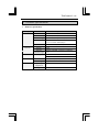
11.1 Product Specifications .................................................................................. 141
ThinConnect4 <1>
Chapter 1 Getting Started
1.1
Feature
1.2
Contents in Package
<2> ThinConnect4
1.1 Features
ThinConnect4 is an integrating HUB, Router, and two high-speed serial interface ports.
The equipment also has IP sharing, E-Mail sharing and Remote Access Service (RAS)
functions. ThinConnect4 is installed as part of Local Area Network (LAN) suitable for a
Small Office Home Office (SOHO).
ThinConnect4 various connection functions
• ISP Dial-Up IP Connection
• ISP Networking Dial-Up IP Connection
• RAS Client Dial-Up IP Connection • Networking Dial-Up IP Connection
• RAS Server IP Connection
• ISP Leased Line IP Connection
• Leased Line IP Connection
• ISP Dial-Up IP Connection + RAS Server IP Connection
• RAS Client Dial-Up IP Connection + RAS Server IP Connection
IP Masquerade
This IP sharing function allows more than one personal computer (PCs) to
simultaneously connect to the Internet.
Call Back
This feature reduces the telephone charges of the individual who calls in and tries to
access a LAN using RAS (Remote Access Service) Server. The ThinConnect4 will call
back a user if the user name and password has been authenticated.
Automatic Connection and Disconnection
Automatic connection:
By starting an Internet application (e-mail, WEB browser
etc.), ThinConnect4 begins Dial-up automatically.
Automatic disconnection: ThinConnect4 automatically disconnects from an ISP when
there is no communication activity for a period of time.
Firewall Protection
By setting the filter information to ThinConnect4 beforehand, the router will monitor all
incoming packet data and protect your network.
DHCP Server
ThinConnct4 has a built-in Dynamic Host Configuration Protocol Server which provides
a dynamic IP address setting for PCs.
E-Mail Sharing
ThinConnect4 has an E-Mail sharing feature which allows all users to have his or her
private e-mail from a single e-mail account.
High Speed Serial Interface
Two RS-232C high-speed serial interfaces with 460.8kbps (Max.) data transmition rate.
Setup Utility
User friendly Setup utility for easy installation, even for a beginner.
Flash ROM
The control program is in Flash ROM. You can easily upgrade firmware if
necessary.
End of 1.1 Feature
ThinConnect4 <3>
1.2 Contents in Package
The following items should be included in your package.
If you are missing any of these items please contact your retailer.
l ThinConnect4
l User’s Manual
l 10BASE-T straight cable
l AC adaptor
l Setup Utility floppy diskette
Note: A copy of the ThinConnect4 Setup Utility diskette is also available at
http://www.expnet.com
End of Contents in Package
<4> ThinConnect4
Chapter 2 Prepare for Installation
2.1
Components of System
2.2
Your ThinConnect4
2.3
How to prepare LAN
2.4
MODEM/TA Installation on Set-Up PC
2.5
2.5.1
2.5.2
2.5.3
Cable Connections
Serial Cable (MODEM/TA)
AC Adapter
10BASE-T Cable (PC connection)
2.6
2.6.1
2.6.2
2.6.3
Windows 95/98 Setting for LAN Connection
Verify the TCP/IP protocol
TCP/IP Installation
TCP/IP Setting
ThinConnect4 <5>
2.1 Components of Systems
The following additional system components needed for setting up a Local Area Network
with the ThinConnect4.
Connecting four PCs or less
• MODEM or Terminal Adapter with DSU (Data Service Unit).
Choose MODEM (regular phone line) or TA (ISDN line) corresponds to your
telephone network. If using TA, please make sure the DSU is included.
• 10BASE-T Ethernet Card (Network Adapter Card)
Install in each PC.
• 10BASE-T Ethernet straight cable (One included in the package)
This cable connects each PC to the ThinConnect4.
Connecting five PCs or more
• All the system’s component in 2.1.1
• Ethernet HUB
If using an Ethernet HUB without a cascade switch, connect a 10BASE-T
crossover cable to the ThinConnect4.
ISP (Internet Service Provider) Connection
Sign up with a reliable ISP (If you do not have one) and obtain the following informations.
• Dial-up communication parameter (Number of Databit, Parity, Stop bit)
• Domain Names Server IP address (Call your ISP customer service)
• Dial-up user ID and Password
• POP3 e-mail server IP address (Call your ISP customer service)
The minimum system requirement using a modem connection
End of 2.1 Components of Systems
<6> ThinConnect4
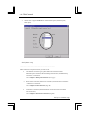
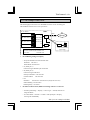
2.2 Your ThinConnect4
l Front Panel
PWR
L1
L2
L3
L4
S1
S2
Monitor LED: Shows ThinConnect4 working status.
S1
Light when serial port 1 is sending/receiving data.
S2
Light when serial port 2 is sending/receiving data.
L1
Light when 10BASE-T port 1 is confirming link or receiving data.
L2
Light when 10BASE-T port 2 is confirming link or receiving data.
L3
Light when 10BASE-T port 3 is confirming link or receiving data.
L4
Light when 10BASE-T port 4 is confirming link or receiving data.
PWR
Light when ThinConnect4 is powered on.
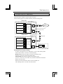
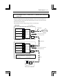
l Rear of ThinConnect4 (Connectors)
9VAC
T1
T2
T3
T4
S1
S2
9 VAC
S1
S2
T4
T3
T2
T1
Port 1: Connects to Ethernet adapter or HUB through 10BASE-T cable.
Port 2: Connects to Ethernet adapter or HUB through 10BASE-T cable.
Port 3: Connects to Ethernet adapter or HUB through 10BASE-T cable.
Port 4: Connects to Ethernet adapter or HUB through 10BASE-T cable.
Serial Port 1: Connects to MODEM or TA.
Serial Port 2: Connects to MODEM or TA.
Power connector: Connects to the AC adapter in the package.
l Right Side of ThinConnect4
OFF
ON
Power Switch: ThinConnect4 power on/off switch.
End of 2.2 Your ThinConnect4
ThinConnect4 <7>
2.3 How to Prepare Your LAN
In order to set up your Local Area Network with the ThinConnect4, we recommend user
set up all the PCs first then the ThinConnect4. One of the PCs on your network should have
ThinConnect4 setup utility installed. A system administrator can configure all the
ThinConnect4 functions from this Set-Up PC.
Setting up your PCs
All PCs should have a 10BASE-T Ethernet card (network adapter card) install along with
associated device driver. Since the installation involves networking, it may need additional
network supporting file or driver. Please have Windows 95/98 CD-ROM or floppy handy
during installation. Some PC may have Windows 95/98 pre-installed. Make sure you know
the path to your Windows 95/98 files.
Note: The ThinConnect4 supports 10BASE-T only. Consult the Ethernet card manual to
verify your card’s interface.
PC running ThinConnect4 Setup Utility (Set-Up PC)
One of the PCs on your LAN should be dedicated as a Set-up PC. Please follow following
steps to complete the installation for the Set-Up PC:
1.
Install ThinConnect4 Setup Utility
(Section 3.1, Page 21 to 32)
Note: The Setup Utility is compatible with Windows 95/98 and Windows NT.
2.
MODEM/TA Installation on Set-Up PC
(Section 2.4, Page 8)
3.
Cable Connections
(Section 2.4, Page 9 to 12)
4.
PC Windows 95/98 settings for LAN Connection (Section 2.6, Page 13 to 19)
Setting up other PCs without ThinConnect4 Setup Utility
For those PCs without the ThinConnect4 Utility, include those PCs connected through a
HUB. Please follow these two steps:
1.
10BASE-T cable (PC Connection)
(Section 2.5.3, Page 11 to 12)
2.
PC Windows 95/98 settings for LAN Connection (Section 2.6, Page 13 to 16)
End of 2.3 How to Prepare Your LAN
<8> ThinConnect4
2.4 MODEM/TA Installation on Set-Up PC
In order to initialize a modem to work with the ThinConnect4 properly, the ThinConnect4
setup utility requires a Modem setup information file (INF file).
User should follow the modem manufacturer instruction. Once the modem is installed the
ThinConnect4 setup utility will be able to select the modem from “Windows” list.
Note: These modem installation procedures apply to the Set-up PC ONLY.
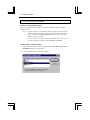
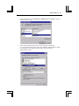
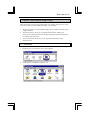
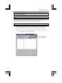
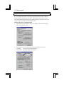
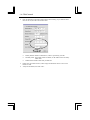
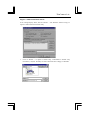
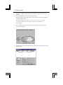
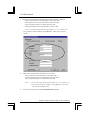
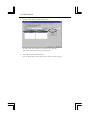
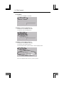
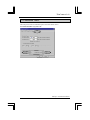
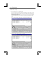
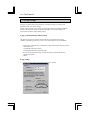
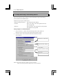
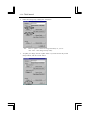
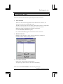
Verify the modem installation
Double-click “My Computer” -> “Control Panel” -> “MODEM”,
the following “Modem Properties” window will show:
Your modem should be listed in the “Modems Properties”.
It is recommended to test the modem by dialing up to your ISP.
Modem or TA setting
The DCD(RLSD) signal from the Modem or TA should be set for active mode.
Example with general AT command:
AT&C1: DCD(RLSD) follows the state of the carrier
Please refer to the modem or TA User’s manual for more details.
Add the AT command to “Extra AT Commands (Page 44)” field if needed.
End of 2.4 MODEM/TA Installation on Set-Up PC
ThinConnect4 <9>
2.5 Cable Connections
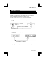
2.5.1 Serial Cable (MODEM/TA)
Use only standard serial cable provided by MODEM or TA. If the cable provided with
MODEM or TA has different shape or PIN assignment, please use proper adapter (not
include) to match the ThinConnect4 serial (S1 or S2) port connector.
Note: Make sure all devices are powered off, before connecting serial cable.
1.
If the modem or TA is currently connected to the PC, remove the serial cable from the
PC side.
PC
Modem/TA
Standard Serial cable for Modem/TA
Removes a cable from
the PC
Modem or TA serial port
2.
Connect a standard serial cable (RS-232) to a serial connector (S1 or S2) on the back
of ThinConnect4.
Modem/TA
ThinConnect4
Standard Serial cable for Modem/TA
Note: If your application need only one modem connects the cable to serial port 1.
Go to next page
<10> ThinConnect4
2.5.2 AC Adapter
Before connecting the AC adapter to ThinConnect4, make sure the power switch
is off.
Connect the power (round) connector into the input socket (9 VAC) in the back of
ThinConnect4.
Plug the AC adapter to a wall receptacle.
ThinConnect4 AC adapter
100-240 VAC input
ThinConnect4 9 VAC power
socket
Observe the following safety precaution
•
•
•
Use the adapter enclosed in this package only. (The output is 9 VAC)
Do not use the power source other than your home/business electric power.
Plug in the AC adapter firmly.
•
•
Do not touch the plug of AC adapter with any metal such as a screwdriver.
Do not pull on the AC cord.
Go to next page
ThinConnect4 <11>
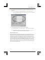
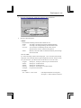
2.5.3 10BASE-T Cable (PC connection)
Turn the PC and ThinConnect4 power off before connecting the Ethernet cable.
1.
Use 10BASE-T straight cable to connect Ethernet adapters and ThinConnect4
10BASE-T ports (T1 to T4).
ThinConnect4
PC
10BASE-T straight cable
ThinConnect4 port T1 to T4
2.
Connecting 10BASE-T port of
Ethernet adapter on PC
Power on ThinConnect4 and PC. Make sure that the Link Rx LED lit up in
correspondence to the 10BASE-T port.
For example: If you connect the cables to port T1 and T3 the Link Rx LED L1 and L3
should light up. If the LED does not light up, go to the next page.
Link Rx LED
PWR L1
Note:
L2
L3
L4
S1
S2
If you are installing your LAN with a HUB to ThinConnect4, make sure the HUB
connection has a cascade (invert lines) switch, otherwise, connect with 10BASE-T
crossover cable.
Insert the RJ-45 connector firmly until you hear a click sound to secure lock of the
cable.
Windows 95 user:
Please proceed to 2.6 PC Windows 95 Settings for LAN Connection
(Page 13 to 19)
<12> ThinConnect4
Troubleshooting the Link RX LED
• Make sure there is power to the ThinConnect4 and PC.
• Check if the RJ-45 connector on both ends is secured.
• Verify the Ethernet card installation on the PC.
Double-click “My Computer”, “Control Panel”, “System”
Click “Device manager”.
Select “Network adapter” from the device menu. Click “+” sign on the left.
Please check if there is mark “!” at front of the Ethernet card name.
If there is a “!” mark, the Ethernet card installation is not complete.
See troubleshooting guide in your Ethernet card User manual for more detail
End of 2.5 Cable connection
ThinConnect4 <13>
2.6 Windows 95/98 Settings for LAN Connection
This section applies to all PCs connect to ThinConnect4.
In order to connect to the Internet successfully, all PCs connected to the ThinConnect4 have
to have the TCP/IP protocol installed and set properly.
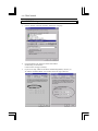
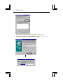
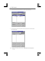
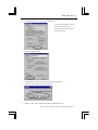
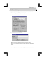
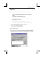
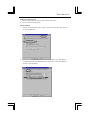
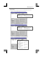
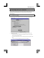
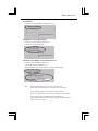
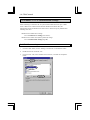
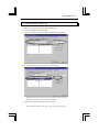
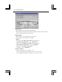
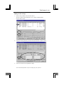
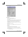
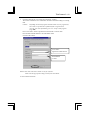
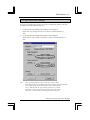
2.6.1 Verify the TCP/IP protocol installation
To verify if TCP/IP protocol is installed properly, please proceed to the following steps.
Double-click on “My Computer” -> “Control Panel” -> “Network”
In Network window, check if TCP/IP is shown and properly set up.
(The following display shows the TCP/IP protocol is already installed.)
If TCP/IP protocol has properly installed, please proceed to 2.6.3 TCP/IP
Settings (Page 16).
If there is NO TCP/IP protocol show in the “Network” window show above, go to the next
page to install TCP/IP protocol.
<14> ThinConnect4
2.6.2 TCP/IP protocol installation
Windows 95/98 CD-ROM requires
During the TCP/IP protocol installation, you will need Windows 95/98 CD-ROM to
complete the task.
Note: 1. If you are working on a PC that has Windows 95/98 pre-installed and the
TCP/IP installation procedures request the Windows 95/98 CD-ROM, you
may try the folder C:\windows\optons\cabs. This is where a copy of the
Windows 95/98 can be found.
2. In some computers the default path for the CD-ROM drive is incorrect. You
may have to adjust the path as needed. (D:\win95 or E:\win95)
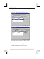
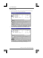
The procedures to install TCP/IP
1.
Please refer to the window on previous page of 2.6.1 Verify the TCP/IP protocol
Installation and click on “Add” button.
2.
Choose protocol and click “Add” below window.
ThinConnect4 <15>
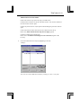
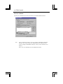
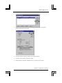
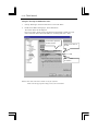
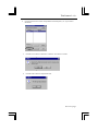
3.
On the window below, choose Microsoft in Manufacturer and TCP/IP in Network
Protocols and click “OK”.
4.
Verify if the TCP/IP protocol has been correctly setup with your Ethernet
card. (The example in the window below using NE2000 compatible adapter) If DialUp Networking is not installed, the system will not show the dial-Up
adapter and the TCP/IP.
<16> ThinConnect4
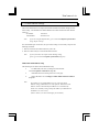
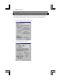
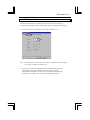
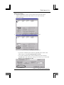
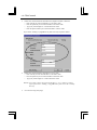
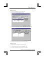
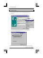
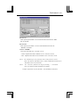
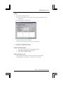
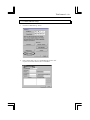
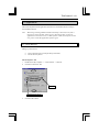
2.6.3 TCP/IP Settings
1.
Choose “TCP/IP -> Ethernet card name” and click on “Property”.
2.
Click “IP Address” Tab and click “Obtain an IP address
automatically”(recommended).
Continue to the next page. (Gateway)
If you are not using “Obtain an IP address automatically (DHCP)” function, set
“IP Address and Subnet Mask”, then continue to the next page. (Gateway)
3.
ThinConnect4 <17>
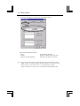
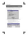
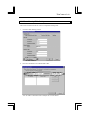
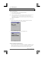
4.
Click the Gateway tab.
In the “New gateway”, put in the ThinConnect4 IP address (Default 192.168.0.1).
Click the “Add” button. New Gateway IP address will be added into the “Installed
Gateways”.
Note:
If you change the ThinConnect4 IP address, make sure the “Installed
gateway” IP address match the ThinConnect4 IP address.
Otherwise the ThinConnect4 Setup Utility will report “No ThinConnect4 on
your network” and prevent further configuration.
The Gateway setting mismatch is the most common mistake in setting the
ThinConnect4 with LAN system.
<18> ThinConnect4
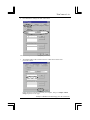
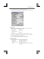
5.
Click “DNS Configuration” Tab and click “Enable DNS” button.
Enter each of the following contents:
• Host:
• Domain:
• DNS Server Searching Order:
PC Host Name (PC name).
DNS Server domain name. (See note)
DNS Server IP Address. (See note)
Note: In general an Internet Service Provider (ISP) will have a Domain Name Server
(DNS). You have to contact the ISP for the name of DNS server and associate IP
address. If there is more than one server, you should enter all of them.
If there is a DNS server on your LAN, you should enter that information here.
ThinConnect4 <19>
6.
Enter DNS Server settings and click “Add” button.
Note: Data example in this window is for reference only.
7.
The DNS IP address will be added on the list of DNS Server Search order.
Click “OK” button.
Please follow the instruction and restart your computer, then go to Chapter 3 Basic
Setup (Required) on next page.
End of 2.6 Windows 95/98 Settings for LAN Connection
<20> ThinConnect4
Chapter 3 Basic Setup
3.1 Installing ThinConnect4 Setup Utility
3.1.1 Before Installation
3.1.2 Installation
3.2 Setup Procedure
3.3 Common Setup
3.3.1 Start Up ThinConnect4 Setup Utility
3.3.2 Searching for ThinConnect4
3.3.3 Nick Name Setup and Confirmation of Firmware Version
3.3.4 ThinConnect4 LAN Settings
3.3.5 DHCP Server Settings
3.3.6 Password Settings
3.3.7 Serial Port option
3.3.8 Settings for MODEM/TA connection
3.3.9 DTE speed
ThinConnect4 <21>
3.1 Install ThinConnect4 Setup Utility
The ThinConnect4 Setup is a utility program helps user configure ThinConnect4’s variety
of functions. Before you start installing the utility, see notes below:
•
•
•
ThinConnect4 utility is on the Installation floppy disk, to install the program requires
a floppy disk drive.
ThinConnect4 utility can only be run under Windows 95/98 or Windows NT.
However, after ThinConnect4 has been properly configured, most Internet functions
are possible from most of OS.
Do not use “Resume” function on your PC (especially notebook PC) under
Windows NT 4.0.
3.1.1 Installation
1.
Double-click on “Control Panel” icon in “My Computer”.
2.
Double-click on “Add/Remove Programs” icon.
<22> ThinConnect4
Click “Install” button.
3.
4.
Insert the ThinConnect4 diskette into the drive and click “Next” button.
The “Add/Remove Program” will search for setup.exe program in the floppy disk and
then display on command line: A:\SETUP.EXE click “Finish”
ThinConnect4 <23>
Follow instructions on the screen. The setup is completed when the following window is
displayed. Click “Finish”
5.
To start the ThinConnect4 setup utility or verify the installation:
• Click the “Start” button on the Task-bar. (Lower left-hand corner)
• Choose “Programs” then ThinConnect4 -> ThinConnect4 Setup Utility.
End of 3.1 Install ThinConnect4 Setup Utility
<24> ThinConnect4
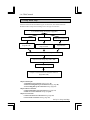
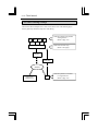
3.2 Setup Road Map
Since the ThinConnect4 have different types of connections, user should consult the
illustration below and proceed according to his or her type of connection.
3.3 Common Setup (Next page to page 47)
Dial-up IP connection
Chapter 4 Dial-up IP
(Page 48 to 69)
RAS Connection
Chapter 5 RAS Connection
(Page 72 to 91)
Leased Line Connection
Chapter 6 Leased Line
(Page 92 to 97)
Chapter 7 Advanced Setting of LAN (Page 98 to 122)
Chapter 8 Final Setting (Page 123 to 128)
Finishing all setup
Chapter 9 Connect/ Disconnect Telephone Network
(Page 129 to 136)
Chapter 4 Dial-up IP:
4.1 ISP Dial-Up IP Connection Settings (Page 48)
4.2 ISP Networking Dial-Up IP Connection Settings (Page 60)
4.3 Networking Dial-Up IP Connection Settings (Page 63)
Chapter 5 RAS Connection:
5.1 RAS Client Dial-Up IP Connection Settings (Page 72)
5.2 RAS Server IP Connection Settings (Page 80)
Chapter 6 Leased Line:
6.1 ISP Leased Line IP Connection Settings (Page 92)
6.2 Leased Line Connection Settings (Page 93)
End of 3.2 Setup Read Map
ThinConnect4 <25>
3.3 Common Setup
3.3.1 Start the ThinConnect4 Setup Utility
Click “Start” button on task bar and select Program ->ThinConnect4 (or other location
assigned during installation) and click on “ThinConnect4 Setup Utility”.
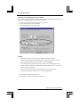
3.3.2 Searching for ThinConnect4
1.
Upon starting up the ThinConnect4 utility, the program will start searching for any
ThinConnect4 connection to the LAN. Click on “Stop” button to stop searching.
Note:
If you have more than one ThinConnect4 on LAN, make sure each one has a
unique IP address to avoid any collision.
Click the button to
stop searching.
<26> ThinConnect4
2.
All ThinConnect4(s) connected with the LAN will be searched and listed.
3.
If the setup utility cannot find any ThinConnect4, check the LAN connection and then
click “Search” again.
Note:
If the list is still empty, please proceed to “ThinConnect4 can not be found” on
next page.
ThinConnect4 <27>
ThinConnect4 can not be found
Follow some of these steps, which may help you trouble shoot:
Check the RJ-45 connectors for the PC and ThinConnect4. The connector should not
be loose and click “Search” again.
Check if the power switch is on (The power LED should light up) and click “Search”
again.
Check if the Link Rx monitor LED in the front of ThinConnect4 is lit up.
Please refer (When Link Rx monitor lamp does not light) page 12.
Check the TCP/IP Protocol setting again.
Please refer to 2.6 Windows 95 Settings for LAN Connection (Page 13 to 19)
PC setup.
4.
Choose the ThinConnect4 to setup by highlighting it and click
“Settings”.
Note: You can exit the ThinConnect4 utility by clicking on “Close” at any time.
<28> ThinConnect4
3.3.3 Nickname Setup and Firmware Version
Nickname Setup
1.
After finishing the setting from 3.3.1 Start the ThinConnect4 Setup Utility
through 3.3.2 Searching for ThinConnect4 (Page 25 to 27), the window below will
be display..
2.
Enter a name you prefer in the “Nickname” field. The maximum string
lengths are 32 characters.
Note: When there are more than one ThinConnect4 on LAN, the nickname will help
user identify each one of them.
In the last window, you can click “Close” button. This will put you back to the
3.3.2 Searching for ThinConnect4 (on page 27 step 4)).
Firmware Version
Below the nickname, there is a field shows the ThinConnect4 firmware version.
You can verify the ThinConnect4 firmware revision here.
ThinConnect4 <29>
3.3.4 ThinConnect4 Settings
This section describes how to setup ThinConnect4 IP address and details setting for LAN
static routing. The IP address and Subnet Mask for the ThinConnect4 have their default
setting as:
IP Address:
192.168.0.1
Subnet Mask:
255.255.255.0
Note:
If you are using the default value, go to section 3.3.5 Options of Serial Port
(Page 37) for next step.
In a normal Dial-Up IP Connection, set up for static routing is not necessary except for the
following conditions:
1. There are more than one ThinConnect4 on your LAN.
2. There are other router(s) on LAN beside ThinConnect4.
Note:
If your system does not require Static Routing setting,
please go to section 3.3.5 Options of Serial Port (Page 37).
ThinConnect4 IP address setup
The following are for ThinConnect4 IP address setup.
•
Use default IP (192.168.0.1) settings for ThinConnect4.
Go to 3.3.5 Options of Serial Port (Page 37).
•
•
Note:
Add ThinConnect4 to existing LAN. Go to next page.
Change IP address. Go to Change/ Confirm ThinConnect4 IP Address
(Page 32).
Even if there is an existing DHCP server in your LAN, the IP
address setting of ThinConnect4 is still required. ThinConnect4 IP
address cannot be distributed from DHCP server automatically.
In this case, manually setting a unique IP address for ThinConnect4
in DHCP server is necessary.
(Please contacts your network manager for all details.)
<30> ThinConnect4
Add ThinConnect4 to existing LAN
If you are adding ThinConnect4 to an existing LAN which IP address setting is different
from ThinConnect4 default value (192.168.0.1, Subnet Mask: 255.255.255.0), then the
ThinConnect4 IP should be changed to meet with those existing setting. Please contact the
network manager for proper IP and Subnet Mask setting.
Changing IP address and Subnet Mask
1.
In the window on page 27 step 4), click on the “Settings”, and then click “Settings”
button in the LAN Port section.
2.
In the window below, enter the IP Address and Subnet Mask you wish to use.
• IP Address:
Enter ThinConnect4 new IP address.
• Subnet Mask: The Subnet Mask of the network.
ThinConnect4 <31>
3.
If all information is correct, click the “OK” button.
The value in the window is just an
example. Please enter your
proper setting to meet with your
LAN requirements.
4.
Click the “Update” button.
5.
Click the “OK” to overwrite the settings made to ThinConnect4, or
click the “Cancel” button to undo the change.
6.
When you click “OK”, ThinConnect4 will be updated and reboot.
The Setup Utility will start searching again. Please refer to section 3.3.2 Searching
for ThinConnect4 (Page 25 to 27) Step 1 to 4) to proceed.
<32> ThinConnect4
Changing and Verifying ThinConnect4 IP Address
If for any reason you wish to change and/or verify the ThinConnect4 IP address, you can do
so by starting the ThinConnect4 set up utility. From the window on page 27 step 4), click
the “Settings” button :
1.
Click the “Settings” button in the LAN Port section.
2.
In the window below, enter the IP Address and Subnet Mask you wish to use.
• IP Address:
Enter ThinConnect4’s new IP address.
• Subnet Mask: The Subnet Mask of the network.
ThinConnect4 <33>
3.
If all information is correct, click the “OK” button.
The value in the window is just an
example. Please enter your
proper setting to meet with your
LAN requirements.
4.
Click the “Update” button.
5.
Click the “OK” to overwrite the settings made to ThinConnect4.
Click the “Cancel” button to undo the change.
6.
When you click “OK”, ThinConnect4 will be updated and reboot.
There is more detail on “Advanced” setting on page 97.
<34> ThinConnect4
3.3.5 DHCP Server Settings
DHCP( Dynamic Host Configuration Protocol) Server provides a dynamic IP address to
PCs connected to the ThinConnect4, follow the steps below to set up the DHCP server:
1.
Click the “Settings” button in LAN Port setup.
2.
Click the “DHCP Server” button.
ThinConnect4 <35>
3.
We recommend user to select “Use DHCP Server Function”.
Otherwise, clear the check mark on “Use DHCP Server Function” and click “OK”.
Factory default:
When the ThinConnect4 IP address is set to default (192.168.0.1), the following
parameters will be set to the DHCP Server setting:
• Start IP Address:
• Subnet Mask:
• Number of Addresses:
192.168.0.2
255.255.255.0
32
• Gateway:
192.168.0.1
As for the above default setting, the IP address distribution pool will start from
“192.168.0.2” for a maximum of 32 Ips which ends at “192.168.0.33”. The DHCP
sever can assign any IP address in this range to a PC.
If you are choosing factory default, continue to the next page.
Change DHCP setting:
Do not set the IP address that will overlap the existing address.
• Start IP Address:
Start IP address pool assign to PC.
• Subnet Mask:
Subnet Mask to assign to PC.
• Number of Addresses:
Setting range is from 1 to 32.
• Gateway:
This setting should be identical to the IP address for
ThinConnect4
<36> ThinConnect4
4.
5.
6.
Enter the DNS Server IP Address both Primary and Secondary (if your ISP have more
than one server) then fill in the Domain name.
•
•
Primary DNS: IP Address of DNS Server, which is provided by your ISP.
Secondary DNS: If Secondary DNS is available, set IP Address in the Secondary
DNS” field.
•
Domain: Enter Domain name from your ISP here.
Please enter the number of hours, which assigns the IP address for PC in the “Lease
Duration” field.
Verify all information, then click “OK”.
ThinConnect4 <37>
3.3.6 Password Settings
To prevent unauthorized changing of ThinConnect4’s operation or parameters, we
recommend setting up a password by follow these steps:
1.
Click the “Password” button.
2.
Enter the same password in two fields.
Make sure you enter an identical password then click the “OK” button.
You are now required to enter a password, in order to change any of ThinConnect4
setting.
Note:
The password will be erased if user upgrades theThinConnect4 firmware.
<38> ThinConnect4
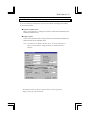
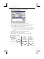
3.3.7 Options for Serial Port
ThinConnect4 has seven basic connecting functions as listed below:
• ISP Dial-Up IP Connection
• ISP Networking Dial-Up IP Connection
• RAS Client Dial-Up IP Connection • Networking Dial-Up IP Connection
• RAS Server IP Connection
• ISP Leased Line IP Connection
• Leased Line IP Connection
When using one serial port, you can choose one of eight types of connections below:
• ISP Dial-Up IP Connection
• ISP Networking Dial-Up IP Connection
• RAS Client Dial-Up IP Connection • Networking Dial-Up IP Connection
• RAS Server IP Connection
• ISP Leased Line IP Connection
• Leased Line IP Connection
• ISP Dial-Up IP Connection + RAS Server IP Connection
• RAS Client Dial-Up IP Connection + RAS Server IP Connection
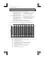
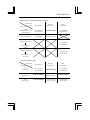
If you are using both serial ports, you can choose one of possible combination below:
Serial Port 1
Serial Port 2
ID
IDS
RC
RCS
RS
IN
N
ND
IL
L
LD
ID
N/A
N/A
N/A
N/A
OK
N/A
OK
N/A
N/A
OK
N/A
IDS
N/A
N/A
N/A
N/A
OK
N/A
OK
N/A
N/A
OK
N/A
RC
N/A
N/A
N/A
N/A
OK
N/A
OK
N/A
N/A
OK
N/A
RCS
N/A
N/A
N/A
N/A
OK
N/A
OK
N/A
N/A
OK
N/A
RS
OK
OK
OK
OK
OK
OK
OK
OK
OK
OK
OK
IN
N/A
N/A
N/A
N/A
OK
N/A
OK
N/A
N/A
OK
N/A
N
OK
OK
OK
OK
OK
OK
OK
OK
OK
OK
OK
ND
N/A
N/A
N/A
N/A
OK
N/A
OK
N/A
N/A
OK
N/A
IL
N/A
N/A
N/A
N/A
OK
N/A
OK
N/A
N/A
OK
N/A
L
OK
OK
OK
OK
OK
OK
OK
OK
OK
OK
OK
LD
N/A
N/A
N/A
N/A
OK
N/A
OK
N/A
N/A
OK
N/A
• ID:
• IDS:
• RC:
• RCS:
• RS:
• IN:
• N:
• ND:
• IL:
• L:
• LD:
• N/A:
• OK:
ISP Dial-Up IP Connection
ISP Dial-Up IP Connection + RAS Server IP Connection
RAS Client Dial-Up IP Connection
RAS Client Dial-Up IP Connection + RAS Server IP Connection
RAS Server IP Connection
ISP Networking Dial-Up IP Connection
Networking Dial-Up IP Connection (without “default gateway” settings)
Networking Dial-Up IP Connection (with “default gateway” settings)
ISP Leased Line IP Connection
Leased Line IP Connection (without “default gateway” settings)
Leased Line IP Connection (with “default gateway” settings)
Not applicable
The serial port combination is allowed.
ThinConnect4 <39>
Serial Port setting
User needs to configure the two high-speed serial ports for usage. Follow step below:
1. Serial port connection setup.
Click “Settings” in “Enable Serial Port 1”
to setup serial port 1.
Click “Settings” in “Enable Serial Port 2”
to setup serial port 2.
2. The “Setting for Serial Port ” will show the Tab for each setting.
• Modem/TA • DTE Speed • Port Usage • Connection timer
Go to next page for each of serial port setup
<40> ThinConnect4
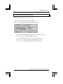
3.3.8 Settings for MODEM/TA connection
Selecting your telephone system
Click on the telephone system type.
• PSTN: Circuit Switched - Tone • PSTN: Circuit Switched - Pulse
• PSTN: Leased Line –Originator • PSTN: Leased Line -Answer
• ISDN: Circuit Switched
• ISDN: Leased Line
Note: Select the telephone system carefully. If the system type is not correct, you may not
be able to connect to your ISP.
ThinConnect4 <41>
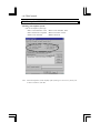
Register a Modem with ThinConnect4
In the “Change Display” below, there are “Browse…” and “Windows” buttons to help you
register a modem with ThinConnect4 utility.
1.
Click on “Browse…” to register a modem using a manufacturer’s modem setup
information (*.inf) file. The utility can either read the file from a floppy or CD-ROM.
<42> ThinConnect4
2.
Click “Windows..” to register a modem from Windows 95/98 or Windows NT modem
list. Select your modem manufacturer from the list. Then click “OK”. Go to the next
step “Choosing MODEM/TA”
Choosing MODEM/TA
1.
2.
Choose a MODEM or TA (Terminal Adapter) from the “Registered MODEM/TA” list
by highlighting the modem.
Click “Select” to confirm your selection. The selected MODEM/TA will be shown in
the “Active MODEM/TA” field.
ThinConnect4 <43>
Change Display
There are three buttons on the ‘Change Display’ to help you select and register a
Modem/TA with the ThinConnect4. The following are the button descriptions:
• “Default” button:
Shows the same list of the modem from My Computer ->Control Panel ->
Modem.
(Usually this is the default list, Window 95 only)
• “Browse” button:
Click to have the ThinConnect4 utility read the modem definition (*.inf file)
from a floppy disk or CD-ROM.
• “Windows” button:
Shows the standard Windows modem for Windows 95 / 98 or
Windows NT. If your modem has been installed in this PC, it will be listed.
If you are connected to “ISDN: Leased Line”, go to next step.
To add “Extra AT Commands” go to Page 44.
Otherwise, skips to 3.3.9 DTE speed Page 45.
ISDN: Leased line Dialing
For user who choose the “ISDN: Leased Line” in Selecting your telephone system type
(Page 40), make sure you enter proper AT command for your modem in “Dial Commands
for leased Line” field. Refer to your Modem/TA user manual. (Default value is ATDT0)
<44> ThinConnect4
Extra AT commands
The extra AT Command may be enter in the Extra AT Command filed show below:
Note:
The AT command entered here overwrites setting for MODEM/TA definition
(INF file). The setting will effect the MODEM/TA in this application only.
It will not modify the MODEM/TA INF file, which you have installed in your
Windows.
Please refer AT commands from your MODEM/TA manual.
ThinConnect4 <45>
3.3.9 DTE Speed
The DTE speed also known as Terminal speed which ThinConnect4 serial ports
communicate with modem. Click on “DTE Speed” Tab, the window below will pop-up.
1. Click on the list box of “DTE Speed”. Then click pull-down arrow.
Note:
The DTE speed is NOT a modem speed, which is usually referred to a telephone
line or DCE, or Modem-to-Modem speed.
2. For a start, try to select the DTE speed equal to the Modem/TA speed or one
selection higher first. This setting will ensure the ThinConnect4 can
communicate with Modem/TA. Later you may experiment with DTE setting
at higher speed. Normally, it set at three times the Modem/TA speed.
<46> ThinConnect4
3.
Please select a proper MODEM/TA communication speed (Terminal speed,
DTE speed).
End of Basic setup
--------------------------------------------Please continue to setup the functions you want to use.
•
For different connection types, please follow the instructions below:
ISP Dial-Up IP Connection, ISP Networking IP Connection, and ISP Dial-Up
Connection + RAS Server
Go to Chapter 4 Dial-Up IP Connection (Next page)
•
RAS Client Connection, RAS Server Connection, and RAS Client Connection
+ RAS Server Connection
Go to Chapter 5 RAS Connection (Page 71)
•
Leased line Connection (ISP Leased line IP Connection and Local Leased
Line Connection)
Go to Chapter 6 leased Line Connection (Page 91)
End of 3.3 Common setup
ThinConnect4 <47>
Chapter 4 Dial-Up IP Connection Setup
4.1 ISP Dial-Up IP Connection
4.1.1 Connection Settings
4.1.2 Address Translation
4.1.3 Detail setting of IP Masquerade
4.2 ISP Networking Dial-Up IP Connection
4.3 Networking Dial-Up IP Connection
4.3.1 Connection Setting
4.3.2 Static Routing Table Settings
4.4 Connection Timer
4.4.1 Automatic Connection
4.4.2 Automatic Disconnection
<48> ThinConnect4
4.1 ISP Dial-Up IP Connection
This section explains how to setup an ISP (Internet Service Provider) dial-up
connection. For details in ISP Networking Dial-Up IP Connection, please go to section 4.2
ISP Networking Dial-Up IP Connection (Page 60).
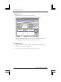
4.1.1 Connection Settings
ISP connection requires a Dial-up user ID, password, and telephone number (point of
present) from your local ISP. Click “Port Usage” Tab for connection setup.
1.
Select “ISP Dial-Up IP Connection” and click “Detail Settings”. If you
want to also use RAS Server at the same port, please select “ISP Dial-Up IP
Connection and RAS Server IP Connection” and click “Detail Settings”.
Note:
The function of the Dial-up relation can be set only to one of
the serial ports 1 or 2. For example, if you set the serial port 1 to
“ISP Dial-UP IP Connection”, you cannot set up another “ISP
Dial-UP IP Connection” or “RAS Client Dial-UP IP Connection”
on serial port 2. You can use “RAS Server IP Connection” or
“Networking Dial-Up IP Connection” or “Leased Line IP
Connection” without the default gateway settings.
Please refer to all the possible function combination of both serial ports
on 3.3.5 Options of serial port (Page 37).
ThinConnect4 <49>
2.
Enter your user ID and password ISP in “User Name” field and “Password” filed
respectively.
Note: For security purpose, the password will show as “****” whatever you
type in. To confirm the password entered please type in your password again in
the “Confirm Password” field.
3.
Fill in the ISP dial-up numbers, in “Phone number #1 through
#3”. The “Phone number #1” is a primary number, # 2 and 3 are alternate numbers.
Note: Please key in the telephone number carefully. If the number is not correct,
ThinConnect4 will keep trying to dial those three numbers.
The Connection process
The Dial-Up Connection (connecting process) to ISP process triggered by user start an
Internet (Web Browser or Mail Software) application. If you have enabled the “Automatic
Connection”(4.4 Connection Timer Page 68) then through the configured serial port the
ThinConnect4 will initialize your MODEM/TA for dialing out. ThinConnect4 will send
commands to MODEM/TA to dial your first phone number “Phone Number #1”. If the line
is busy or cannot connect for some reason, MODEM/TA will reply “Cannot connect” and
ThinConnect4 will attempt to dial your second number “Phone number #2” (if one was
assigned). If “Phone number #2” cannot connect, ThinConnect4 will try to dial your third
phone number “phone number #3” (if one was assigned). If all three attempts fail, please
restart your Internet application again.
<50> ThinConnect4
Internet Application setting
Your Internet application needs to be configured before using with it ThinConnect4.
Follow the instructions
Setting for WEB browser:
•
Choose LAN connection (Do not setup as Dial-up connection)
•
Do not use Proxy server.
Internet Explorer 4.x
1.
Double click on “My Computer” - > “Control panel” -> “Internet”
Click on “Connection” tab.
2.
Choose “Connect to the Internet using a local area network”
Uncheck “Access the Internet using a local area network”
Click “OK’ after you have finished.
3.
ThinConnect4 <51>
Setting for e-mail program:
•
Choose LAN connection. (Do not setup as dial-up connection)
•
Do not check the mail frequently.
Internet Mail 3.0
1. Choose “View” from menu, select “option”, and click “Connection” Tab. Choose “I
use a LAN connection”.
2.
Click the “Read” Tab. Uncheck “Check for new messages every”. This setting is
recommended because the ThinConnect4 does not have to connect to the ISP and
check for e-mail frequently.
<52> ThinConnect4
4.1.2 Address Translation
This section explains two types of the IP address translation available as a part of the many
feature of the ThinConnect4.
IP Masquerade
Normally, when you sign up with a local ISP for the Internet, that account is usually valid
for only one user. This type of address translation allows you to share a single account with
multi-users. The maximum 256 sessions are available. For the popular web browser and
e-mail programs, each PC is considered to occupy 10 sessions. That is, about 20 PCs can
run Internet applications at the same time through one single connection. Some application
softwares may not be compatible under IP Masquerade. In this case select NAT (Network
Address Translation) instead.
NAT (Network Address Translation)
NAT allows multiple PC connection together, but while one PC is connected to the
Internet, others cannot be connected at the same time.
1.
If you want to connect all PCs to Internet at the same time, select “IP Masquerade” in
the “Address Translation” window below.For sequential connection one at a time,
choose “NAT”.
ThinConnect4 <53>
2.
To setup the “Translation Table”, pull down the “Aging Time” list box and
choose a time period.
What is Setup Aging Time?
The “Aging Time” means if a PC is not using the Internet for the setup
time period, ThinConnect4 will relocate the connection to the next PC.
In a situation which ThinConnect4 exceeds 256 sections in the “IP masquerade” or
one user is already logged on in the “NAT”, the other user will not be able to access
the Internet.
If there is an idle connection and the “Aging timer” counter goes to zero,
ThinConnect4 will automatically relocate the connection to the next user.
<54> ThinConnect4
4.1.3 Detail Settings of IP Masquerade
This setup is optional and only needs to be done if IP Masquerade is selected.
This function translates the IP frame, which begins the connection with the Internet.
Maximum entry is 32.
Game Server
Client PC
Internet
Modem
ThinConnect4
PC
Click the “Details” button.
WWW Server
FTP Server
ThinConnect4 <55>
1. Enter the entry number in “No” field. (Maximum entry is 32)
2. Click the “Add” button after entering the entry number.
3. Entry field will show. (If you want to quit listing, click the “Abort” button.)
<56> ThinConnect4
4.
5.
Under the “Translation Table” section, click “Protocol”, and choose the type of
protocol.
Enter the port number in the “Start Port Number” field.
When specifying a range of port numbers, please enter the end of the port number in
“End Port Number” field.
For well-known ports, it is possible to enter it with protocol or service name.
Just click the “Well-known Ports” button and refer to “Well-known Ports:
Keyword Table”
6.
Enter the IP address you want to translate in the “Translation IP Address” field.
7.
Click the “Enter” button.
8.
Selected entry number will be added on the list. When the settings are finished, click
the“OK” button.
ThinConnect4 <57>
Setting Example
Assume the IP address of target PC is 192.168.0.100. Following field will be shown.
Example 1: If you are setting WWW server into your LAN
Protocol
Start Port Number
: TCP
: www-http (Port Number: 80)
Example 2: Starting FTP server into your LAN.
Protocol
Start Port Number
End Port Number
: TCP
: ftp-data (Port Number: 20)
: ftp (Port Number: 21)
Example 3: When playing DIABLO V1.05 (Network battle game).
<Entry Number 1>
Protocol
Start Port Number
<Entry Number 2>
Protocol
Start Port Number
<Entry Number 3>
Protocol
Start Port Number
: TCP or UDP
: 116
: TCP or UDP
: 118
: TCP or UDP
: 6112
<58> ThinConnect4
Editing the setting
1.
Select the entry number from the list you wish to edit.
Selected entry number will be displayed on “No.” field on “Static IP Masquerade
Table”. Click the “Edit” button to make changes.
2.
Change the setting value which you want to edit. Once done, click the “Update” button
for the changes to take effect.
3.
The newly changed items will be displayed on the list.
Note: The data information is just an example for your reference.
ThinConnect4 <59>
Remove the settings
1.
Select the entry number, which you want to delete from the list and click the
number. Selected entry number will be shown on “No” field of “Static IP
MasuqueradeTable”.
2.
Entry number will be deleted if you click the “Remove” button.
Note: The data information is just an example for your reference.
• If you choose “ISP Dial-Up IP Connection” (Page 48), please click the “OK”
button and go to section 4.4 Connection Timer (Page 68).
• If you choose “ISP Dial-Up IP Connection and RAS server IP Connection”
(Page 48), please click “RAS Server Settings” and continue to go to section 5.2
RAS Server IP Connection (Page 80).
End of 4.1 ISP Dial-Up IP Connection
<60> ThinConnect4
4.2 ISP Networking Dial-Up IP Connection
ISP Networking Dial-Up IP Connection service is one of the functions which is provided
by an ISP. To use this function, it is necessary to have an account with a local ISP.
1.
After you choosing “ISP Networking Dial-Up IP Connection” in “Port Usage”, click
the “Detail Settings” button.
2.
In the authentication section, choose your authentication method. In the Dial out
section, enter your user name and password.
•
•
•
Select your authentication as both dialing outs and receiving
calls. Please choose “Dial out and Receive calls”.
If you want to make your authentication to receive calls only, please
choose “Receive calls only”.
If you do not want any authentication, please choose “Nothing”.
ThinConnect4 <61>
About Authentication
• Dial out and receive calls.
Dial-up Connection
ThinConnct4
ISP
The ISP confirms whether the Dial-Out authentication data and the authentication data
of the ISP are the same once ThinConnect4 sends it. At the same time, ThinConnect4
confirms whether the authentication data, which the ISP sent and the Receive Calls
authentication data which ThinConnect4 sent, are the same. Once this confirmation has
been completed, it will connect to the ISP.
Dial-up Connection
ThinConnct4
ISP
ThinConnect4 confirms whether the authentication data, which the ISP sent and the
Receive calls authentication data sent by ThinConnect4, are the same. At the same time,
the ISP authenticates whether the Dial-Out authentication data, which ThinConnect4
sent with the authentication data sent by the ISP, are the same. If both procedures have
been confirmed, ThinConnect4 will start to logon to the ISP.
• Receive calls only.
Dial-up Connection
ThinConnct4
ISP
ISP confirms whether the Dial-Out authentication data, which ThinConnect4 sent and
the authentication data sent by the ISP are identical. If settings are confirmed, it will
logon to the ISP.
Dial-up Connection
ThinConnct4
ISP
ThinConnect4 authenticates whether the Receive calls authentication data it sent and
authentication data sent by ISP are identical. If settings are confirmed, it will logon to
the ISP.
• Nothing
Connect without authentication at both sides.
Dial-up Connection
ThinConnct4
ISP
Dial-up Connection
ThinConnct4
ISP
<62> ThinConnect4
3.
Please enter the authentication information and telephone number to Dial Out.
Enter your user ID you received from ISP in “User Name” field.
Enter the password you received from ISP in “Password” field.
Type your password again in “Confirm Password” field.
Enter phone number you received from ISP in “Dial to” field.
Note: For security reasons, the password will show as “****” whatever you
have typedIf you choose “Nothing” on page 60 item 2, please enter only phone
number.
4.
Please enter the authentication information to receive calls.
Enter user ID you received from ISP in “User Name” field.
Enter the password you received from ISP in “Password” field.
Type your password again in “Confirm Password” field.
Note::
5.
For security reasons, the password will show as “****” whatever you
have typed. If you choose “Nothing” on page 60 item 2 please click
“OK” directly and skip this step.
Click the “OK” button and go to 4.4 Connection Timer (Page 68).
End of 4.2 ISP Networking Dial-Up IP Connection
ThinConnect4 <63>
4.3 Networking Dial-Up IP Connection
Setup for private Networking Dial-Up IP Connection becomes a similar function of
Remote Site Network and Leased Line by connecting both directions dial-up IP for
PSTN and ISDN.
4.3.1 Connection Settings
1.
After you choose “Networking IP Connection” in “Port Usage”, click the “Detail
Settings” button.
2.
In authentication method, please enter your user ID, password and choose your
authentication method.
• If you want to be able to authentication both dial out and receive calls, please
choose “Dial out and Receive calls”.
• If you want to authentication on receive calls only, please choose “Receive calls
only”.
• If you do not want any authentication, please choose “Nothing”.
<64> ThinConnect4
3.
Please enter the authentication information and telephone number to Dial Out.
•
•
•
•
Enter user ID you received from ISP in “User Name” field.
Enter the password you received from ISP in “Password” field.
Type your password again in “Confirm Password” field.
Enter the phone number you received from ISP in “Dial to” field.
If you choose “Nothing” in page 60 item 2) please enter only the phone number.
4.
Please enter the authentication information to receive calls.
• Enter user ID you received from ISP in “User Name” field.
• Enter the password you received from ISP in “Password” field.
• Type your password again in “Confirm Password” field.
Remark: For security reasons, the password will show as “****” whatever you have
typed. If you choose “Nothing” in page 60 item 2 please click “OK” and skip
this step.
5.
Go to the next step (Next page).
ThinConnect4 <65>
4.3.2 Static Routing Table Settings
This section contains instructions on how to setup Static Routing table.
1.
Click the “Static Routing” button.
2.
Enter the “IP Address” and “Subnet Mask” field.
Note: IP address and Subnet Mask will define the network address.
<66> ThinConnect4
3.
Click the “Add” button to add the setting to list.
The value in the above window is for reference only. Enter the
appropriate setting to meet your LAN environment.
4.
Click “OK” after all records are listed.
Note: To edit or delete records, please refer to the steps on the next page.
ThinConnect4 <67>
Edit listed record
1.
Click once to highlight the record you wish to edit.
2.
Click the “Edit” button and make the change.
3.
After you have finished editing, click the “Add” button to save your changes.
4.
Click “OK” when finished with setup (Add, Edit, or Delete).
To delete a record
1.
Highlight the record you want to edit by clicking on it.
2.
Click the “Delete” button to delete the highlighted record.
3.
Click “OK” when finished with setup (Add, Edit, or Delete).
End of 4.3 Networking Dial-Up IP Connection
<68> ThinConnect4
4.4 Connection Timer
This section explains the setup procedures for “Connection Timer”.
Click on the “Connection Timer” Tab.
4.4.1 Automatic Connection
l Enable Auto-Connection
Upon starting an Internet application (web browser, E-mail program),
ThinConnect4 will automatically start dial-up to ISP.
l Disable Auto-Connection
If selected, user will need to start Setup Utility and then click the “Connect”
button which corresponds to a serial that is connected to a MODEM/TA.
The default value is “Disable Auto-Connection”.
ThinConnect4 <69>
4.4.2 Automatic disconnection
Setting the automatic disconnection. There are two types of setup available.
l Non Activity Timers
ThinConnect4 will automatically disconnect when there is no communication for a
certain period of time.
You can setup the “Non Activity Timers” to monitor the transmitting and receiving
data separately.
l Set Non Disconnect Timer Period
ThinConnect4 will automatically disconnect when the clock reaches the ending time.
Non Activity Timers setup
1.
Enter the holding time you want to set (Between 10 seconds to 600 minutes)
in “Non Transmit Timer”.
2.
Enter the holding time you want to set (Between 10 seconds to 600 minutes)
in “Non Receive Timer”.
Note: The default value is 3 minutes.
If you are connecting to a WEB site that is actively showing
advertisement or updated information, the Non-Activity-Timer will not
function.
• If you wish to setup the “Set Non Disconnect Timer Period”, continue on to the next
page.
• If you do not want to setup “Set Non Disconnect Timer Period”, click
“OK” and go to chapter 7 Advanced settings of LAN (Page97).
<70> ThinConnect4
Setting up “Set Non Disconnect Timer Period”
User can stay connected with ISP by specify the time period based on the PC’s time of day
clock. The setting will overwrite the “Non Activity Timer”.
1.
2.
3.
Check on “Set Non Disconnect Timer Period” check box.
Enter starting hour (0 to 23) and minutes.
Enter ending hour (0 to 23) and minutes.
Caution:
• Make sure the clock on your PC is correct. When clicking the “Settings”
button of the Setup Utility, ThinConnect4 will acquire the current time of your PC
and synchronize the internal clock with the PC clock automatically.
• If for some reason the ThinConnect4 power is off, the “Set Non Disconnect Timer
Period” function will becomes invalid. Restart the Setup Utility again so it will read
the correct time from your PC.
• When you select “Set Non Disconnect Timer Period”, ThinConnect4 will
automatically disconnect when the clock reaches the ending time.
Click the “OK” button to exit this setting.
Go to Chapter 7, Advanced settings of LAN (Page97).
End of 4.3 Connection Timer
ThinConnect4 <71>
Chapter 5 RAS IP Connection Setup
5.1 RAS Client Dial-up IP Connection
5.1.1 Connection Settings
5.1.2 Call Back Function
5.1.3 IP Address Acquiring/Assigning
5.1.4 Address Translation
5.1.5 Detail Settings of IP Masquerade
5.2 RAS Server IP Connection
5.2.1 Connection Types (Setup IP Address)
5.2.2 Client Access/Call Back
5.3 Connection Timer
5.4 Windows NT 4.0 Authentication Settings
5.4.1 RAS Server Settings
5.4.2 Client Settings
<72> ThinConnect4
5.1 RAS Client Dial-Up IP Connection
ThinConnect4 (set up as a RAS client) connects to a remote RAS server by using PSTN and
ISDN.
5.1.1 Connection Settings
1.
Click “Port Usage” tab, then choose “RAS Client Dial-Up IP Connection” ,
and click ”Detail Settings” button.
If you want to use RAS Server on the same port, please choose “RAS client Dial-Up IP
Connection and RAS server IP Connection” and click the “Detail Settings” button.
Note:
The function of the Dial-up relation can be set only to one of
the serial ports 1 or 2. For example, if you set the serial port 1 to
“ISP Dial-UP IP Connection”, you cannot set up either “ISP
Dial-UP IP Connection” or “RAS Client Dial-UP IP Connection”
on serial port 2. You can use “RAS Server IP Connection”,
“Networking Dial-Up IP Connection”, or “Leased Line IP
Connection” without the default gateway settings.
Refer to the possible functional combinations of two serial ports
on 3.3.5 Options of serial port (Page 37).
ThinConnect4 <73>
2.
Enter the user name on the “User Name” field.
Enter the password on the “Password” field for this user name.
Note:
For security reasons, the password will show as **** whatever you have
typed. To verify any typing, please enter the password again in the
“Confirm Password” field.
Caution: Make sure there is a matching user name and password on the RAS server
you have tried to access, otherwise you cannot connect with the server.
3.
Enter the RAS Server's phone number in “Phone Number” field.
Caution: Type in the phone number carefully. If the number
is incorrect, ThinConnect4 will keep trying to dial this given number.
<74> ThinConnect4
5.1.2 Call Back Function
This section explains how to set up the call back function. The following are available
functions:
l No Call Back
No Call back setting. (Page 76)
l Call Back to “Preset in RAS Server”
Call Back requests to the telephone number, which has been preset at the RAS
server.
(Page 76)
l Call Back of “Set by RAS Client to”
Call Back requests the telephone number specified in RAS client.
(Page 76).
Note: The call back function should be enabled on both RAS Server side and RAS
Client side. If the settings are different, ThinConnect4 will not connect.
The Call back function is not valid if RAS Server activated
with Windows 95-Plus! Dial-Up Server need to be set as “No Call
Back” in this section.
ThinConnect4 <75>
The ThinConnect4 will perform the following steps if ThinConnect4 client settings are
different with RAS server setting:
Windows 95 with “Microsoft Plus!” RAS Server
Plus! Server
No Call back
ThinConnect4 Client
No Call back
Can connect at
"No call back"
Preset in
RAS Server
Set by
RAS Client
Can not connect
Can not connect
Windows NT 4.0 with standard RAS Server
NT Server
No Call back
ThinConnect4 Client
Preset in
RAS Server
Set by
RAS Client
No Call back
Can connect at
"No call back"
Can not connect
Preset in
RAS Server
Can not connect
Can connect at
"Preset in server"
Can not connect
Set by
RAS Client
Can not connect
Can connect at
"Preset in server"
Can connect at
"Set by client"
“No call back”
connection
ThinConnect4 with RAS Server
ThinConnect4 Server
No Call back
Preset in
RAS Server
Set by
RAS Client
ThinConnect4 Client
No Call back
Can connect at
"No call back"
Can not connect
Preset in
RAS Server
Can not connect
Can connect at
"Preset in server"
Can not connect
Set by
RAS Client
Can not connect
Can connect at
"Preset in server"
Can connect at
"Set by client"
“No call back”
connection
<76> ThinConnect4
No Call Back
• Leave “Use Call Back” unchecked.
Call Back of “Preset in RAS Server”
• Check the “Use Call Back” check box.
• Choose the “Preset in RAS Server”.
Call Back of “Set by RAS Client to”
• Check the “Use Call Back” check box.
• Choose the “Set by RAS Client to”.
• Enter the RAS Client’s phone number in “Phone Number” field.
Note: The telephone number above is just for reference.
ThinConnect4 <77>
5.1.3 IP Address Acquiring/ Assigning
If you are connecting to a RAS Server, there are two methods of assigning the IP address
for ThinConnect4 client.
l Acquires from RAS Server
Select “Get by RAS server”. During the connection, ThinConnect4 will allocates the
IP address from RAS Server.
l Assign by Client
Choose “Preset by RAS Client to” during connection, ThinConnect4 will allocate IP
address for RAS Server from RAS Client.
Note: For RAS Server in Windows 95-plus, choose “Preset by RAS Client to”.
Make sure the IP Address setting for RAS Server and RAS Client are
identical.
The information above is only for reference. Please enter the appropriate
setting to meet your LAN environment.
<78> ThinConnect4
5.1.4 Address Translation
This section explains the IP address translation setting for ThinConnect4.
The ThinConnect4 utilizes two types of address IP Masquerade and NAT.
•
IP Masquerade
Normally, when you sign up with local ISP for the Internet that account is usually
valid for only one user. This type of address translation allows you to share a single
account with multi-users. The maximum of 256 sessions is available. For the
popular web browser and e-mail programs, each PC is considered to occupy 10
sessions. That is, about 20 PCs can run Internet applications at the same time
through one single connection. Some application software may not be compatible
under IP Masquerade. In this case select NAT (Network Address Translation)
instead.
•
NAT (Network Address Translation)
NAT allows multiple PC connection together, but while one PC is connected to the
Internet, others cannot be connected at the same time.
Please refer to 4.1.2 Address Translation on page 52 to 59 for setup.
ThinConnect4 <79>
5.1.5 Detail settings of IP Masquerade
This setup is optional you can proceed if necessary.
This setup is the same as the ISP Dial-Up IP Connection.
Please refer to 4.1.3 Detail settings of IP Masquerade (Page 54).
• If you choose “RAS Client Dial-Up IP Connection” in the window on page 72,
click “OK” and go to 5.3 Connection Timer (Page 87).
• If you choose “RAS Client Dial-Up IP Connection and RAS server IP
Connection” in the window on page 72, click “RAS Server Settings”
and continue to go to 5.2 RAS Server IP Connection (Next page).
End of 5.1 RAS Client Dial-Up IP Connection
<80> ThinConnect4
5.2 RAS Server IP Connection
The following figure is a typical RAS Server IP Connection:
IP: IP Address
IP: 192.168.0.2
PC 1
IP: 192.168.0.3
PC 2
IP: 192.168.0.4
PC 3
IP: 192.168.0.5
PC 4
IP: 192.168.0.6
PC 5
IP: 192.168.0.254
RAS Client
IP: 192.168.0.1
ThinConnect4
Server IP: 192.168.0.253
Client IP: 192.168.0.254
HUB
5.2.1 Connection Types (Setup IP Address)
1.
Click “Port Usage” Tab. Choose the “RAS Server IP Connection” and click “Detail
Settings”.
ThinConnect4 <81>
2. Enter IP Address in “RAS Server IP Address” and “RAS Client IP Address”.
Do not to overlap another IP Address. But, it is possible to set the same IP
Address of ThinConnect4 in “RAS Server IP Address”. If you have selected the “Same
as LAN Port”, the ThinConnect4 IP Address will be set in “RAS Server IP Address”
fields.
If you wish to have the IP address assigned from DHCP server, check the
“Use DHCP on ThinConnect4 to assign IP addresses” check box.
The value in the above window is only for reference. Enter the appropriate
setting to meet with your LAN environment.
The RAS Client IP Address used during a connection to RAS Server is assigned by RAS
Server. If ThinConnect4 is functioning as a RAS Server, it will set RAS Client to IP
Address acquisition mode.
<82> ThinConnect4
5.2.2 Client Access/Call Back
1.
Enter the name in “User Name” field.
Enter the password in “Password” field.
Type your password again in “Confirm Password” field.
Remark: For security reasons, the password will show as “****” whatever you have
typed.
2.
Choose your call back setting.
l No Call back
No Call back setting.
l Call back for “Set by RAS Client”
ThinConnect4 connects to the telephone number of the RAS Client specification.
l Call Back to “Preset in RAS Server to”
ThinConnect4 connects to previously registered telephone number.
ThinConnect4 <83>
No Call back
• Uncheck “Accept Call Back” and leave it as it is.
Call back for “Set by RAS Client”
Check the “Accept Call Back” check box.
• Choose the “Set by RAS Client.
Call back to the number “Preset in RAS Server”
Check the “Accept Call Back” check box.
• Choose the “Preset in RAS Server to”.
• Enter the RAS Server’s phone number in “Phone Number” field.
Note:
The telephone number above is just for reference only.
Please enter the actual number you want to used as call back.
Verify callback number you have entered. If the number is
not correct, ThinConnect4 will continue to dial the wrong number.
The call back settings should match on both RAS Server
side and RAS Client side. If the settings are different, ThinConnect4
will not be able to connect.
<84> ThinConnect4
3.
When finishing your Call back setting, click the “Add” button.
The record will be added in the box.
Note:
4.
To edit or remove the listed record, please refer to page 86.
When all records have been listed, enter the “Ring Count”. ThinConnect4 will answer
log in requests after the “Ring Count” has been set (1 to 99, Default is set to 2)
when finished with the setting, click the “OK” button.
Note: If you have other telephone devices connected to the same line as the Modem,
please choose the “Ring Count” carefully. For telephones, the setting should be
higher than 2 (i.e. 15) so you have a chance to pick up the phone before the
Modem does.
If the settings between RAS Server and RAS Client are different, the
following combination of the setting will take effect.
(For following tables: NT 4.0 = Windows NT 4.0, Win 95 = Windows 95/98)
Windows 95 Dial-Up Connection
ThinConnect4
Win95 Client
Server
No Call back
Call back pop up
window is “OK”
Call back pop up
window is “Cancel”
No pop up window
Can connect at
"No call back"
Preset in
RAS Server
Set by
RAS Client
Can connect at
"Preset in server"
Can connect at
"Set by client"
Can not connect
Can connect at
"No call back"
ThinConnect4 <85>
Windows NT 4.0 Standard Dial-Up Connection
ThinConnect4
Server
No Call back
NT 4.0 Client
Disable
PPP LCP extensions
(No Call back)
Enable
PPP LCP extensions
Preset in
RAS Server
Can connect at
"No call back"
Can not connect
Can connect at
"No call back"
Can connect at
"Preset in server"
Enable
PPP LCP extensions
Set by
RAS Client
Can connect at
"No call back"
Can connect at
"No call back"
pop up window is
“Cancel”
Enable
PPP LCP extensions
Can connect at
"Set by client"
pop up window is
“set by client”
ThinConnect4 RAS Client
ThinConnect4
ThinConnect4
Server
No Call back
Preset in
RAS Server
Set by
RAS Client
Client
No Callback
Can connect at
"No call back"
Can not connect
Can connect at
"No call back"
Preset in
RAS Server
Can not connect
Can connect at
"Preset in server"
Can not connect
Set by
RAS Client
Can not connect
Can connect at
"Preset in server"
Can connect at
"Set by client"
<86> ThinConnect4
Edit listed record
1.
Highlight the record you want to edit by clicking on it.
2.
Click the “Edit” button and edit the information you want to change.
3.
When you have finished editing, click the “Add” button to update your changes.
Click “OK” when you have finished setup (Add, Edit, or Delete).
To remove a record
1.
Highlight the record you want to remove by clicking on it and click the “Remove”
button. Click “OK” to confirm the removal.
2.
Click “OK” when you have finished setup (Add, Edit, or Remove).
End of 5.2 RAS Server Setup
ThinConnect4 <87>
5.3 Connection Timer
This setup is the same as in ISP Dial-Up IP Connection. Please refer to
4.4 Connection Timer (Page 68 to 70).
End of 5.3 Connection Timer
<88> ThinConnect4
5.4 Windows NT 4.0 Authentication Settings
When connecting to a Windows NT 4.0 system and the ThinConnect4 set up as a RAS
client or RAS server of ThinConnect4 from the Windows NT’s RAS client, the
authentication setting for Windows NT must be set to “Allow/Accept any authentication
including clear text”.
• Windows NT 4.0 RAS Server settings
Go to 5.4.1 RAS Server settings (next section).
• Windows NT 4.0 RAS Client (Dial-up Network) settings
Go to 5.4.2 RAS Client settings (Page 90)
5.4.1 RAS Server settings
1.
Click the “Start” button, choose “Settings”, and click the “Control Panel” button.
2.
Double-click on the “Network” icon.
3.
Click “Services” Tab, choose “Remote Access Service”, and click the “Properties”
button.
ThinConnect4 <89>
4.
Click the “Network” button.
5.
Choose the “Allow any authentication including clear text” button of “Encryption
settings” and click the “OK” button.
6.
Click the “Continue” button in “Remote Access Setup” window.
7.
Click the “Close” button in “Network” window.
8.
Please follow the instruction of Windows NT 4.0, and reboot your computer.
End of 5.4.1 RAS Server settings
<90> ThinConnect4
5.4.2 Client settings
1.
Double-click “My Computer” button, select “Dial-Up Networking”, and
double-click.
2.
Click the “More” button, choose “Edit entry and modem properties”.
3.
Click “Security” tab for “Edit Phonebook Entry” and choose “Accept any
authentication including clear text”.
When finished with setting, please Go to Chapter 7 Advanced settings of LAN (Page 97).
End of 5.4.2 Client settings
ThinConnect4 <91>
Chapter 6 Leased Line Setup
6.1 ISP Leased Line IP Connection
6.2 Leased Line IP Connection
6.2.1 Default Gateway Setup
6.2.2 Static Routing Table Setup
<92> ThinConnect4
6.1 ISP Leased Line IP Connection
This section explains the setup for ISP Leased Line IP Connection.
Choose ISDN Leased Line beforehand in “3.3.8 Settings for MODEM/TA connection”.
(Page 40 to 44)
IP = IP Address
Leased Line
IP: xxx.xxx.0.2
IP: xxx.xxx.0.3
S1
ThinConnect4
IP: xxx.xxx.0.4
255.255.255.0
ISP
Internet
TA
xxx.xxx.0.1
IP: xxx.xxx.0.5
ISP Leased Line IP Connection
(Default Gateway)
S2
1.
Click “Port Usage” Tab.
Choose “ISP Leased line IP Connection”.
2.
Click the “OK” button.
3.
Configuring “Detail Settings” is not required for “ISP Leased line IP connection”.
You can click “Cancel” to get out of the “Detail Settings” section.
Note:
Use TA that matches your Leased Line connection.
In the “ISP Leased Line IP Connection” setting, the serial port
becomes a default gateway.
Please go to Chapter 7 Advanced settings of LAN (Page 97).
End of 6.1 ISP Leased Line IP Connection
ThinConnect4 <93>
6.2 Leased Line IP Connection
This section shows example of a point to point connection.
See the following figure and set Default Gateway and Static Routing Table.
Head office
IP = IP Address
ISP
IP: xxx.xxx.0.2
IP: xxx.xxx.0.3
S1
ThinConnect4
IP: xxx.xxx.0.4
255.255.255.0
Leased Line
TA
Internet
xxx.xxx.0.1
Leased Line IP Connection
(Static Routing Table)
S2
IP: xxx.xxx.0.5
Branch office
TA
Leased Line IP Connection
(Default Gateway)
Leased Line
IP: xxx.xxx.1.2
S1
IP: xxx.xxx.1.3
IP: xxx.xxx.1.4
IP: xxx.xxx.1.5
TA
ThinConnect4
xxx.xxx.1.1
255.255.255.0
S2
Modem
Modem
Home or Remote Site
l Default Gateway and Static Routing
As shown in the figure above, the “Head office” is set for “Static Routing Table”
and the “Branch office” is the side to “Default Gateway”.
Default Gateway sends only packet except the use IP address range
(xxx.xxx.1.1 to xxx.xxx.1.255) to the branch office.
Static Routing Table sends only packet in the IP address range
(xxx.xxx.1.1 to xxx.xxx.1.255) which was specified with IP address and Subnet
Mask to the branch office.
When the side of the head office doesn't connect with ISP, uses
“Static Routing Table” as the side of the branch office.
<94> ThinConnect4
6.2.1 Default Gateway Setup
This section shows you how to setup “Detail Settings”.
1.
Click the “Port Usage” Tab.
Choose “Leased Line IP Connection” and click “Detail Settings”.
2.
Check the “Default Gateway” check box.
ThinConnect4 <95>
6.2.2 Static Routing Table Setup
This section shows you how to setup Static Routing Table.
1. Enter the IP address and Subnet Mask.
Remark: IP address and Subnet Mask will define the network address.
2.
Click the “Add” button to list the record of the IP address.
The value in the above window is only for reference. Please enter the
appropriate setting to meet your LAN environment.
3.
When all records are listed, click the “OK” button
Note: To edit or delete records, please refer the steps on next page.
<96> ThinConnect4
Edit listed record
1.
Highlight the record you want to edit by clicking on it.
2.
Click the “Edit” button and edit the record you want to change.
3.
When you finish editing, please click “Add” to save your changes.
4.
Click the “OK” button when finished the setup (Add, Edit, or Delete).
To delete a record
1.
Highlight the record you want to edit by clicking on it.
2.
Click the “Delete” button to delete the highlighted record.
3.
Click “OK” when finished the setup (Add, Edit, or Delete).
End of 6.2 Local Leased Line Connection
ThinConnect4 <97>
Chapter 7 Advanced LAN Setting
7.1 Firewall - IP Filter Table settings
7.2 Static routing settings
7.3 Syslog settings
7.4 E-Mail sharing settings
7.4.1 ThinConnect4 Setup
7.4.2 To Setup mailer using E-Mail Sharing function
7.4.3 To setup a mailer sending mail to registered user
<98> ThinConnect4
7.1 Firewall - IP Filter Table setting
Setup the Firewall - IP Filter Table is optional. ThinConnect4 can function without it. The
firewall function is a packet filtering gateway process. After the firewall is setup properly,
PC resources on LAN will be protected by the IP filtering function that is placed in between
LAN IP frame and WAN (Serial Port) IP frame.
Caution:
For this type of IP address setting you should have a good knowledge oft
TCP/IP. Please be very careful in setting up this section because a wrong setup
may cause ThinConnect4 to stop working. Unless it is necessary to change the
settings, we suggest that you to use the default setting on the next page.
Layer3 Filtering Control
Processing protocol is objected filtering control for IP frame only.
Other layer3 protocol (IPX) will be all closed down.
Layer4 Filtering Control
Processing protocol is objected filtering control for ICMP, TCP and UDP.
Other layer4 protocol (EGP, OSPF) will be transparent.
Layer5 Filtering Control
• ICMP Control: No control
• TCP Control: Monitoring port number and flag.
• UDP Control: Monitoring port number.
1.
Click the “Firewall - IP Filter Table” button in the “Settings for LAN Port”.
Note: Data in the window is an example for your reference. Please enter your
proper setting to meet with your LAN requirements.
ThinConnect4 <99>
Firewall Factory default setting
The following items are the ThinConnect4 Firewall default setting.
•
Interdict automatic connection of circuit by ICMP.
•
Shut out to supply NetBIOS Services to other networks from LAN port.
(Interdict automatic connection of circuit by Windows startup and finish)
•
Interdict automatic connection of circuit beside TCP connection (SYN) flag.
(Interdict automatic connection of circuit by the end of application)
•
Interdict automatic connection of circuit by BOOTP, TFTP.
•
Interdict automatic connection of circuit by Apple Talk.
Note: The above 5 items is applicable to use on the same LAN.
Caution: If you change or delete the default value of any items mentioned above, the
Firewall will become ineffective. This may cause user unable to use dial-up
function, or to make connection with dial-up. Try to correct the setting or set
IP filter to the default value.
Click the “Return to Default” button to reset all the “Firewall - IP Filter Table” to
return to the default value.
• Listing for filter setting proceed to the next page.
• To Editing for filter setting proceed to page 105.
• To Removing for filter setting proceed to page 106.
<100> ThinConnect4
Listing for filter setting
1.
Enter a number in the “No” (number) field.
The entry number represents the IP filter processing priority, which number 1 is the
highest and number 64 is the lowest. There are five default values which have been
predefined for ThinConnect4.
For example: Enter number 6 if you want your setup at a lower priority than default
value. Enter number 1 if you can make your setup priority higher than the default
value.
Or any setting between 2 to 5 according to the priority. (Maximum entry 64)
2.
Click “Add” button after entering an entry number.
ThinConnect4 <101>
3.
Items entry field will show. All the entry functions can be defined here.
4.
Item entry filed descriptions.
“Action”
ThinConnect4 IP filtering functions that available for user.
According to the settings transparent nominated IP frame.
• CUT:
According to the settings blocking-off nominated IP frame.
• NC:CUT:
“No Connection cut” Blocking-off only when circuit is
disconnected. If circuit is connected, transparent it.
• MON:
Monitor (count) the number of nominated IP frame passes through
the ThinConnect4.
• PASS:
“IN” and “OUT”
“In” shows the setting of ThinConnect4 input port. “Out” shows the ThinConnect4
output port, and set IP frame and the object through ThinConnect4. Always set both
“IN” port and “OUT” port. Please choose on the list box of “IN” and “OUT”.
• Anyport:
Serial port 1, serial port 2, and LAN port of ThinConnect4.
• SIO:P1:
Serial port 1 of ThinConnect4.
• SIO:P2:
Serial port 2 of ThinConnect4.
• SIO:any:
Serial port 1 and serial port 2 of ThinConnect4.
• LANport:
LAN port of ThinConnect4.
Example:
“IN” = SIO: P1 “OUT”=LAN:
If the objected IP frame receiving from
serial port 1, it will be routed to LAN side.
<102> ThinConnect4
“IP/Mask: Src.”
Select IP address or Network address from the Source.
Enter IP address/sub net masks bit numbers in the filed, if the sub masks bit numbers
is omitted, that single IP address will be chosen.
“IP/Mask: Dst.”
Select IP address or Network address from Destination.
Enter the same way as “IP/Mask: Src.” settings.
Example:
• When object is IP Address: 192.168.0.1, Network Address of
Subnet Mask: 255.255.255.0 –> enter “192.168.0.1/24”
• When object is IP Address: 192.168.0.1, Network Address of
Subnet Mask: 255.255.255.128 –> enter “192.168.01/25”
• When object is IP Address: 192.168.0.44 of
IP Address –> enter “192.168.0.44”
“IP/Mask: AND/OR”
Active only when both “Src.” and “Dst.” are set.
• “AND”: Objected when both conditions of “Src.” and “Dst.” are met.
• “OR”: Objected when either one condition of “Src” or “Dst.” is met.
ThinConnect4 <103>
“Port No: Src.”
Select protocol port number or service from the Source and enter the “Port
No” on the field.
“Port No: Dst.”
Select protocol port number or service of the Destination and enter the
“Port No” on the field.
“Port No: AND/OR”
Active only when both “Src.” and “Dst.” are set.
• “AND”: Objected when both conditions of “Src.” and “Dst.” are met.
• “OR”: Objected when either one of conditions of “Src.” and “Dst.” is met.
Note1:
For well-known port, it is possible to enter it with protocol or service
name. Just click the “Well-known Ports” button of ThinConnect4 and refer to
“Well-known Ports: Keyword Table”
Note2:
“Src.” and “Dst.” field can set a range by inserting “ / ” between the
source port number and the destination port number.
Example: Objected area, from (201/208) = 201(AT-RMTP) to 208(AT-8).
<104> ThinConnect4
“Protocol:”
Choose in the list box of “Protocol”.
• Any:
Objected for all IP frame.
• ICMP: Objected for ICMP protocol.
• TCP:
Objected for TCP protocol.
• UDP:
Objected for UDP protocol.
“Flags”
Select one of the six flag types for the objected TCP protocol.
• URG:
Flag for urgent.
• ACK:
Flag for acknowledgement
• PSH:
Flag for push.
• RST:
Flag for reset.
• SYN:
Flag for synchronization
• FIN:
Flag for final.
If you click the "flag name" button, the following indications will display in sequence.
• (XXX): Not objected flag (disregard).
• +XXX: Objected if the flag is on (bit 1).
• -XXX: Objected if the flag is off (bit 0).
XXX each name of flag will be in.
If [+XXX] and [-XXX] are combined and all conditions are met it will
object only (AND).
5.
Click the “Enter” button after finishing all settings.
The entry number will be added on the list. If your entry number is an already existing
number the new entry will be listed after such number.
All IP frames that are not objected on entry list will be transparent.
ThinConnect4 <105>
Editing for filter settings
1.
Select an entry-number from the list and click it.
The entry number will be displayed on “No.” field on “IP Filter Table”
click the “Edit” button.
2.
Change the setting value that you want to edit, then click the “Update” button.
3.
Check if the ThinConnect4 updated the change.
Note: The data information is just an example for your reference.
<106> ThinConnect4
Remove filter settings
1.
Click on an entry number, which you want to delete from the list. The selected entry
number will be shown on “No” field of “IP Filter Table”.
2.
The entry number will be deleted when you click the “Remove” button.
Note: The data information is just an example for your reference.
End of 7.1 Firewall - IP Filter Table settings
ThinConnect4 <107>
7.2 Static Routing Settings
This setup is optional. It is not necessary for the function of ThinConnect4. With this
setting, ThinConnect4 can transfer the received packet to the other router.
It sets up the Network and Gateway address.
•
Routing setup according to registered current routing information
The packet on authorized network address will be transferred to the other
router assigned by gateway address.
•
Using default LAN gateway
The packets on authorized routing information and the other IP addresses
within a LAN will be transferred to the IP address (router) assigned by
default gateway.
Note: ThinConnect4 can setup one default gateway only. If you choose any of
the connection types below, ThinConnect4 serial port becomes the
default gateway.
• ISP Dial-Up IP Connection
• RAS Client Dial-Up IP Connection
• ISP Networking Dial-Up IP Connection
• ISP Leased Line IP Connection
If you select the “Use Default Gateway on Your LAN” box, the following
function are available:
• RAS Server IP Connection
• Networking Dial-Up IP Connection”
• Leased Line Connection (without default gateway)
<108> ThinConnect4
1.
Click the “Static Routing” button and the static routing window will pop up.
2.
Choose to use default gateway or static routing.
• To use default gateway, check the “Default Gateway” check box.
• The setting of “Static Routing table” is a higher priority than “Default Gateway”.
The value in window is an example only. Please enter your proper setting to
meet your LAN requirement.
Please refer to Chapter 10 Examples (Page 136 to 139)
ThinConnect4 <109>
Listing
1.
Enter IP address and Subnet Mask
Note: The Network address will be defined by the combination of IP address and
Subnet Mask.
Enter gateway address (router address)
The value in window is just an example.
Please enter your setting to meet with your LAN requirements.
2.
3.
Click “Add” to add the data to the list.
Click “OK” to confirm all records enter.
Edit the listed information
1.
2.
3.
If you want to change a listed record, highlight the item.
Click “Edit” and edit the record of settings.
Click “Add” to update the change.
Remove the listed record
When removing the listed record, select the content you want to remove
by highlighting it. Click “Remove” to remove the record from list.
End of 7.2 Static Routing settings
<110> ThinConnect4
7.3 Syslog settings
Syslog is a system messages recording utility. This utility will log event and system
information (This is an option setting).
Usually system messages can be sent/received through a network by using the UDP Port
514. Most of UNIX host, which records those messages as the system messages are
received and recorded by Syslog demon process.
Syslog event/information in ThinConnect4
The ThinConnect4 current firmware has the following event/information logging
capability. (Depending on firmware version, some of the functions may not available)
• Record “AT” commands sent to modem/TA on both serial and the response received
from Modem/TA.
• Confirm PPP connected sequence.
• Confirm global IP address provided by ISP.
• Record connecting/disconnecting, confirm connecting, disconnecting time and
communicating time.
• Others.
Syslog settings
1.
Click the “Syslog” button in “Settings for LAN Port” window.
ThinConnect4 <111>
2.
Setting screen Syslog.
Setting up items
•
Check box for “Enable Syslog Function”:
Place a check in this box to enable Syslog function.
•
“Host IP Address”:
Enter a receivable “Host IP Address” of Syslog. The receivable IP address should
be the same as ThinConnect4, which means it must correspond to the LAN side
address of the same network. If you enter 255,255,255,255 the Syslog
event/information will be broadcasted to the LAN within the same segment of
ThinConnect4.
If you use syslog demon corresponding to broadcasting IP, you can receive syslog
with multiple PCs at the same time.
• “Facility Code”:
ThinConnect4 always use LOG_USER as the facility code and this setting is not
changeable.
• “Message Type”
Check the message type check box of each Syslog option.
At present, ThinConnect4 has two messages type available: “LOG_INFO” and
“LOG_WARNING”. In the future, more message functions will be added by
firmware version upgrade.
Note: At present, Syslog demon program services have not implemented. Contact
technical support for detail.
End of 7.3 Syslog settings
<112> ThinConnect4
7.4 E-Mail sharing settings
This function allows multiple users to share one E-mail account. The following figure
shows typical steps needed to setup the e-mail sharing.
PC
PC
PC
7.4.2 Setup mailer using E-Mail
sharing function
(Refer to page 116)
PC
7.4.1 ThinConnect4 setup
(Refer to next page)
ThinConnect4
Modem
Send mail
Internet
POP3 Server
SMTP Server
PC
7.4.3 Setup mailer to send mail
to a registered user
(Refer to page 118)
ThinConnect4 <113>
7.4.1 ThinConnect4 Setup
1.
Click the “E-Mail Sharing” button.
2.
Place a check mark in the “Use E-Mail Sharing function” box.
If you do not use this function, leave it unchecked.
<114> ThinConnect4
3.
Setup a mail server connection
Enter POP3 server IP address onto “POP3 Server “ field.
Enter the E-Mail account registered with POP3 Server in “E-Mail Account” field.
Enter a password in the “Password” and “Confirm Password” fields. If you do not
have password, leave it empty.
4.
Register users who are going to share the e-mail account.
Enter user names in “User Name” field.
Enter password to “Password” and “Confirm Password” fields.
If user corresponds with a non-registered user, then place a check mark on “Receive
non-registered incoming mail”.
5.
Please click the “Add” button. User information will be added to the list.
Note: For security reason, the password will show as “***” whatever you have typed.
The value in the above window is only for reference.
Please enter the appropriate setting to meet your environment.
ThinConnect4 <115>
Edit listed record
1.
Click on a user you want to change from list.
Selected registered Information will be highlighted.
2.
Click the “Edit” button. Selected listed information will be shown on each
item box fort you edit and change.
3.
After you finish editing, click the “Add” button, the information entered
will be updated.
Remove listed record
1.
2.
Click on a user you want to remove from the list.
Selected registered Information will be highlighted.
Click the “Remove” button for it to be deleted from the list.
When you are finished with “Add” “Edit” and/or “Remove”, click the “OK” button.
<116> ThinConnect4
7.4.2 Setup mailer using E-Mail Sharing function
This section describes setup procedures for each individual PC using E-Mail Sharing
function featured in the ThinConnect4.
Follow the setup sequence outlines below.
• POP3 (Incoming mail) Server
• Accounts
• Password
Enter ThinConnect4 IP Address.
Enter “User Name”. This is the registered user from
Item 4 on page 114.
Enter “Password”. This is password for the registered
user from Item 4 on page 114.
Setup example for “Outlook Express”
1.
Click “Accounts” in “Tools” menu in the startup window. Click “Mail” tab.
Select the account you want to setup and click the “Properties” button.
2.
Click the “Server” tab. The window mentioned will be shown. Please
enter as follows:
SMTP server name of ISP
ThinConnect4 IP Address
“User Name”
registered in ThinConnect4
“Password”
registered in ThinConnect4
Remark: The value in the above window is only for reference.
Please enter the appropriate setting to meet your environment
ThinConnect4 <117>
3.
Click the “General” tab, you will see the “Properties” window.
This section contains the user’s information. It will be used when sending or receiving
mail.
Caution: Depending on the mail programs which the sender use, the program may
not be able to respond to the replied mail from a registered user
correctly. For more information go to 7.4.3 “Setup e-mail program”
(Page 120).
Enter “User Name” which is registered in ThinConnect4 to “Name” field.
Enter the shared E-mail address to “E-mail address” field.
Click the “OK” button.
“User Name”
registered in ThinConnect4
E-mail address
to share
Remark: The value in the above window is only for reference.
Please enter the appropriate setting to meeth your environment
4. Close “Internet Accounts”.
<118> ThinConnect4
Setup for “Netscape Communicator 4.07”
1.
Start up “Messenger” and click “Preferences” in the “Edit” Menu.
2.
Double click “Mail & Newsgroups”, Click “Mail Server”.
The window below will be displayed.
Enter “User Name” whom you have registered in ThinConnect4 to “Mail server user
name” field. Enter ThinConnect4 IP Address to “Incoming mail server:” field.
“User Name” registered
in ThinConnect4
SMTP server name of
the ISP
ThinConnect4
IP Address
Remark: The value in the above window is only for reference.
Please enter the appropriate setting to meet your environment.
ThinConnect4 <119>
3.
Click on “Identity” and the window will be shown. This is a mail user’s information,
which will be used to send and receive e-mail
Enter “User Name” that is registered in ThinConnect4 to “Your name:” field.
Enter the share E-mail address to “E-mail address” field.
And click the “OK” button.
“User Name” registered in
ThinConnect4
E-mail address
to share
Note:
The value in the above window is only for reference only.
Please enter the appropriate setting to meet your environment.
Caution: Be careful while choosing to leave mails on the server, do not exceed the
server storage quota; otherwise, the new mail may not be noticed.
<120> ThinConnect4
7.4.3 Setup E-mail program
This section describes how to configure e-mail program for sending mail to ThinConnect4
user with the E-mail sharing function. Please ask the sender to set up e-mail program
according to following procedures:
In order to send mail to users, who are using an E-Mail sharing function, it is necessary
for the e-mail program to have either one of these two conditions or both, otherwise it will
not work.
•
A program that allows user to enter an address in “User name”<E-mail account>
format in the “To” field. For example:
“John”<[email protected]>
•
A program which can set “User name”<E-mail account> in "To" field by “Address
book”.
Setup example of “Outlook Express” will be shown in below.
1.
Click “Address Book” in “Tools” menu at startup window.
Click the “New Contact” button. The window below will be shown.
Enter the “User Name” registered in ThinConnect4 to "Display" field.
Enter the shared E-Mail address at ThinConnect4 to “Add New” field.
Click the “Add” button.
2.
Click the “OK” button and close “Address Book”.
Note1:
Note2:
“John” will be shown in the address field at the time of sending
but actually mail will be sent to "John"<[email protected]>.
The value in the above window is only for reference.
Please enter the appropriate setting to meet your environment.
ThinConnect4 <121>
Notes on sending mail
•
Users who are using an E-Mail sharing function can not receive mail which are sent
out as “Cc”. Please send out as “To”.
•
If you want to send mail to multiple receivers, you can not include users who are
using the E-mail Sharing function. Please send directly to the one who is using Email Sharing function.
•
The “Messenger” in Netscape Communicator can not set up “User Name”<E-mail
Account> address format. The format is not available from the "To" or "Address
Book".
End of 7.4 E-mail Sharing Settings
<122> ThinConnect4
Chapter 8 Final Setup
8.1 Save your settings
8.2 Return to Default
8.2 To Copy Serial Port Settings
ThinConnect4 <123>
8.1 Save your settings
To make sure ThinConnect4 configuration will take effect, this section instructs you
how to save your settings correctly.
1.
Basic setups
Click “OK” in the window at “Setting for Serial port 1 (or 2)” setup if you
want to confirm your settings. Otherwise Click “Cancel” if you do not want to save
any changes.
<124> ThinConnect4
2.
Enable the serial ports by enabling their check boxes.
Note:
3.
Click on “Update” to make the change immediately. Or, you can
click “Close” when ending the Setup Utility.
To update your change, click the “Update” button. If you want to leave the previous
Setup condition, click the “Cancel” button.
ThinConnect4 <125>
4.
When this window pops up, you can click “OK” to update the settings made to
ThinConnect4. Otherwise, click ”Cancel”.
Note: When you click “OK”, the ThinConnect4 will automatically restart
again. All current communications will be disconnected.
In case the ThinConnect4 connects with a Leased Line, ThinConnect4 will start
to reconnect immediately soon after it restarts.
5.
Click the “Close” button.
Please go to Chapter 9 Connect/ Disconnect Telephone Network (Page 128)
End of 8.1 Save your settings
<126> ThinConnect4
8.2 Return to Default
This section instructs you how to load the factory default values.
1.
Refer 3.3.1 Start ThinConnect4 Setup Utility (Page 25) to start up Setup Utility.
2.
To load factory default value to serial port 1, click the “Return to default” button in
serial port 1.
To load factory default value to serial port 2, click the “Return to default” button in
serial port 2.
To load factory default value to LAN port, click the “Return to default” button in
LAN port.
End of 8.2 Return to Default
ThinConnect4 <127>
8.3 Copy Serial Port Settings
If you have successfully setup a serial port and want to duplicate all settings to the other
port, ThinConnect4 has this function for you.
1.
If you want to copy settings of Serial port 2 to serial port 1.
Please click “Copy settings of serial port 2” button on “Enable Serial Port 1”
field.
2.
If you want to copy settings of Serial port 1 to serial port 2.
Please click the “Copy settings of Serial port 1” button on “Enable serial port 2”
field.
Note:
The Copy setting function will overwrite any previous setting.
If the serial port has been enabled before Copy setting, it will become disable.
For example, at the time the check mark is on the “Enable Serial
Port 1” and you click the“copy settings of serial port 2” button,
Serial port 2 settings will overwrite on serial port 1 and “Enable
Serial Port 1” the check mark will disappear from serial port 1.
End of 8.3 To Copy Serial Port Settings
<128> ThinConnect4
Chapter 9 Connect / Disconnect
Telephone Network
9.1 Applications
9.1.1 Web browser
9.1.2 E-mail program
9.2 Connection Types
9.3 Disconnect the network
9.3.1 PSTN and ISDN
9.3.2 Leased Line
ThinConnect4 <129>
9.1 Application
This section explains Internet application (Web browser and E-Mail software) setting to
use with ThinConnect4.
Note:
When using an analog Modem and with auto Dial-up connection, it may take a
long time to connect the ISP. A time-out error may happen after you start an
application such as Web browser, E-Mail software or FTP client software. In this
case, please restart that application software again.
9.1.1 Web browser
Setting up a web browser:
•
•
LAN Connection. (Do not setup as dial up connection)
Do not use Proxy Server
Internet Explorer 4.01
1. Double-click “My Computer” -> “Control Panel” -> “Internet”
2. Click the “Connection” Tab.
Click this
Uncheck Proxy server
3.
Click the “OK” button.
<130> ThinConnect4
9.1.2 E-mail program
Set up an e-mail application:
•
LAN Connection. (Do not setup as dial up connection)
•
Do not check the mail frequently
Note:
When using ISP Dial-Up IP Connection function and other similar Dial-up, try to
avoid using the automatic e-mail retrieval feature in the E-Mail software.
You should be aware the program will dial-up regularly and it may add telephone
charges every call to ISP.
Internet Mail 3.0
1.
Choose “View” from menu, select “option”, and click “Connection” Tab to get
window shown below. Choose “I use a LAN connection”.
2.
Click “Read” Tab. Uncheck “Check for new messages every”.
Set up to checking new message interval.
In case you choose “Check for new messages every X minute”, (Substitute “X” with
number of the minute interval of your choice) the ThinConnect4 will start internal
timer after ThinConnect4 disconnects by the “Non Activity Timers” function.
End of 9.1 Applications
ThinConnect4 <131>
9.2 Connection Types
This section describes different kinds of public telephone network connection.
•
Auto connection
When a user starts an Internet application such as Web browser, E-mail etc, the
ThinConnect4 will connect automatically to ISP.
The dial-up network screen will not be shown. ThinConnect4 will use its configuration
based on the ISP information you have provided to connect to the Internet.
Make sure to check the “Enable Auto-Connection” function box.
See 4.4.1 Automatic Connection (Page 68).
Note: PING and NetBIOS program cannot initiate an Auto- Connection
•
Manual connection
Highlight a serial port that you wish to connect from the list by clicking on it.
Click the “Connect” button on serial port 1 (or 2).
•
Leased line connection
Switch on TA, and then switch on ThinConnect4.
After powering on ThinConnect4, it will connect automatically.
Please refer to 9.3.1 PSTN and ISDN for Disconnecting (Next page).
End of 9.2 Connection Types
<132> ThinConnect4
9.3 Disconnect the network
This section shows various methods of disconnecting from the network..
9.3.1 PSTN and ISDN
•
Automatic Disconnection
There are two kinds of automatic disconnection. (See detail set up 4.4.2 Automatic
disconnection, Page 69).
•
1.
The line can be disconnected by the “Non Activity Timers” function of
ThinConnect4.
2.
The line can be disconnected by the “Set Non Disconnect Timer Period” function
of ThinConnect4.
Manual Disconnection
By using the ThinConnect4 Setup Utility, you can disconnect the line directly.
1.
Choose a ThinConnect4 to disconnect from the list. The highlighted one will be
available for disconnection operation.
ThinConnect4 <133>
2.
Click the “Disconnect” button corresponded to the Serial ports (1 or 2) you wish to
disconnect.
3.
Click the “Yes” button to disconnect. Click the “No” button to resume.
4.
Click the “OK” button to complete the task.
Go to next page
<134> ThinConnect4
5.
If the following screen is displayed, most of the time is because of the equipment is
malfunctioned.
Click the “OK” button to clear the box..
The following could be the a reason to cause the error:
• MODEM/TA’s malfunction
• ThinConnect4 malfunctioned
• Abnormal Cable (LAN and Serial) connect or disconnect.
6.
Click the “Close” button to end Setup Utility
Note: Your ISP’s non-activity timer can also disconnect ThinConnect4.
End of 9.3.1 PSTN and ISDN
ThinConnect4 <135>
9.3.2 Leased Line
Basically, you can not disconnect a leased line, however, you can switch off the TA’s
power supply if you want to disconnect the Leased line.
To connect the leased line again, please refer to 9.2 Connection Types (Page 131)
End of 9.3 Disconnect the network
<136> ThinConnect4
Chapter 10 Examples
10.1
10.2
An example of the ISP <-> Head office <-> Branch office
leased line connection
An example with ISDN
ThinConnect4 <137>
10.1 An example of ISP <-> Head office <-> Branch office leased line
connection
With the configuration like the following illustration, a user can access the Internet via
company head office from branch office and from home. Of course, user can access the
Internet from the head office.
The IP address and static routing setting is shown on the next page.
Head office
IP = IP Address
Leased Line
ISP
IP: xxx.xxx.0.2
S1
IP: xxx.xxx.0.3
ThinConnect4
IP: xxx.xxx.0.4
255.255.255.0
xxx.xxx.0.1
IP: xxx.xxx.0.5
Internet
TA
Leased Line IP Connection
(Static Routing Table)
S2
TA
Branch office
Leased Line
IP: xxx.xxx.1.2
S1
IP: xxx.xxx.1.3
IP: xxx.xxx.1.4
IP: xxx.xxx.1.5
TA
ThinConnect4
Leased Line IP Connection
xxx.xxx.1.1
(Default Gateway)
255.255.255.0
S2
Modem
RAS Server
RAS Server Serial Port IP:
xxx.xxx.1.253
IP for Client:
xxx.xxx.1.254
Modem
Home or Remote Site
(RAS Client)
PSTN
<138> ThinConnect4
•
IP and Router settings in Head office
• Setting of IP for ThinConnect4
IP address: xxx.xxx.0.1
Subnet Mask: 255.255.255.0
• S1 (Serial port 1)
Connection Type: ISP Leased Line IP Connection
• S2 (Serial port 2)
Connection Type: Leased Line IP Connection
Static Routing Table:
IP address: xxx.xxx.1.0
Subnet Mask: 255.255.255.0
• PCs
IP address: xxx.xxx.0.2 to xxx.xxx.0.254 (avoid duplication)
Subnet Mask: 255.255.255.0
Default gateway:xxx.xxx.0.1
•
IP and Router settings in Branch office
• ThinConnect4
IP address: xxx.xxx.1.1
Subnet Mask: 255.255.255.0
• S1 (Serial port 1)
Connection Type: Leased Line IP Connection
This serial port is on default gateway setting
• S2 (Serial port 2)
Connection Type:
RAS Server
Serial port IP address: xxx.xxx.1.253
Client IP address:
xxx.xxx.1.254
• PCs
IP address:
xxx.xxx.1.2 to xxx.xxx.1.252 (avoid duplication)
Subnet Masking: 255.255.255.0
Default gateway: xxx.xxx.1.1
•
IP address for RAS Client (Windows 95 setting) at home or remote site.
• In Dial-up networking -> Property -> Server Type -> TCP/IP, select “Server
assign IP address”
• In Control Panel -> Network -> TCP/IP -> Dial up adapter ->Property,
choose get IP automatically.
End of 10.1 An example of ISP <-> Head office <-> Branch office leased line connection
ThinConnect4 <139>
10.2 An example with ISDN
The following figure shows RAS Server MODEM connection via the TA analog port.
The IP address and RAS Server are set up as shown.
Office
IP = IP Address
S1
IP: 192.168.0.3
ThinConnect4
IP: 192.168.0.4
255.255.255.0
Internet
TA
192.168.0.1
IP: 192.168.0.5
S2
PSTN
Modem
RAS Server
RAS Server (Serial Port) IP: 192.168.1.253
IP for Client :
•
ISP
ISDN
IP: 192.168.0.2
Modem
Home or Remote Site
(RAS Client)
192.168.1.254
IP and Routing settings in Company
• Set up the IP address for ThinConnect4 itself
IP address: 192.168.0.1
Subnet Mask: 255.255.255.0
• S1 (Serial port 1)
Connection Type: ISP Dial-Up IP Connection
• S2 (Serial port 2)
Connection Type: RAS Server
Serial port IP address: 192.168.0.253
Client IP address: 192.168.0.254
• PCs
IP address:
192.168.0.2 to 192.168.0.252 (unique for each user)
Subnet Masking: 255.255.255.0
Default gateway: 192.168.0.1
•
IP address for RAS Client (Windows 95 setting) at home or remote site.
• In Dial-up networking -> Property -> Server Type -> TCP/IP, select Server
assign IP address
• In Control Panel -> Network -> TCP/IP -> Dial up adapter ->Property,
choose get IP automatically.
End of 10.2 An example with ISDN
<140> ThinConnect4
Chapter 11 Reference Information
11.1 Product Specifications
ThinConnect4 <141>
11.1 Product Specifications
•
Hardware Specification
Category
Serial Port
Item
Port No.
Interface
Connector Type
DTE
Flow Control
Specifications
2 ports
V.24/V.28 (RS-232C)
9pin D-sub (S1) / 25pin D-sub (S2)
1.2 /2.4 /4.8 /7.2 /9.6 /14.4 /19.2 /28.8 /38.4
57.6 /115.2 /230.4 /460.8 (Kbps)
Hardware Control (RTS/CTS)
LAN Port
Port No.
Interface
Connector Type
Power
AC Adapter
INPUT : AC 100/120/230/240V 50/60 Hz
OUTPUT: AC 9V 1000 mA
Outlook
Dimension
Net Weight
131 (W) x 191 (D) x 29 (H) mm
400g
Environment
4 ports
IEEE802.3/ISO8802-3 CSMA/CD 10BASE-T
RJ-45
Operating
0 to 40C
Temperature
Operating humidity 25 to 85%
<142> ThinConnect4
•
Serial Port Connector
• Pin assignment
Signal
Serial Port 1
9pin D-Sub
Serial Port 2
25pin D-Sub
DCD
1
8
RXD
2
3
TXD
DTR
3
4
2
20
GND
DSR
RTS
5
6
7
7
6
4
CTS
RI
8
9
5
22
• Connector pin assignment:
2
1
6
4
3
7
8
5
9
Serial Port 1: 9pin D-Sub
2
3
4
5
6
7
8
20
22
Serial Port 2: 25pin D-Sub
End of 11.1 Product Specifications