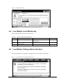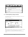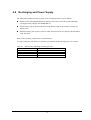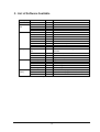
1
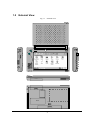
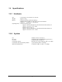
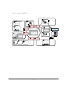
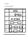
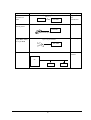
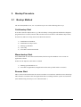
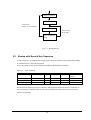
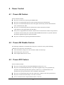
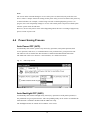
PA-2400
Software Manual
(Version 1.00 )
March 1998
Casio Computer Co., Ltd.
Copyright ©1998. All rights reserved.
Table of Contents
Chapter 1.
1.1
1.2
1.3
1.3.1
1.3.2
1.3.3
1.3.4
Chapter 2.
2.1
Chapter 3.
3.1
3.2
Chapter 4.
4.1
4.2
4.3
4.4
Chapter
Chapter
Chapter
Chapter
Chapter
Chapter
4.5
4.6
4.7
4.8
5.
6.
6.1
6.2
7.
8.
9.
9.1
9.2
10.
10.1
Overview
Features
External View
Specifications
Hardware
System
Basic Specifications
CPU
Memory
Display Unit
Application
Option
Operation
System Configuration
Bootup Procedure
Bootup Method
Cold-bootup Start
Warm-bootup Start
Resume Start
Startup with Special Key Sequence
Power Control
Power-ON Factors
Power-ON Disable Factors
Power-OFF Factors
Power Saving Process
Auto Power OFF (APO)
Auto Backlight OFF (ABO)
Low Battery Level Monitoring
Low Battery Voltage Alarm Indication
Remaining Battery Voltage Indication
Recharging and Power Supply
List of Software Available
Input Method
Key Input
Alphanumeric Input Pad
Fonts
Registry
Application Development Environment
Overview
Software Development Procedure
Appendix
Difference from PA-2500 (US Ver. 2.0)
2
3
3
4
5
5
5
7
7
7
7
7
8
9
9
11
11
11
11
11
12
13
13
13
13
14
14
14
15
15
16
17
18
19
19
19
20
21
22
22
22
24
24
1.
Overview
This manual gives the specifications of the software that operates on the H/PC (Casio PA-2400).
The H/PC uses the Windows CE US Ver 2.0 operating system.
The Casio PA-2400 is the next model up from the PA-2100 (CASSIOPEIA Pen Version with
Japanese-language OS Ver1.01) .
This H/PC has been developed for export. It has pen input capability and is based on the
CASSIOPEIA Key Version for export, which is the generic consumer model that is similar to
the Japanese-language Ver1.01 model.
1.1
Features
This H/PC has the open-plat form OS of Windows CE US Ver 2.0 (by Microsoft Corporation)
pre-installed.
Table 1.1 Comparison
Item
Windows CE Ver 2.0
1. OS environment
Network compatible *
Print function added.
Sound and backlight controllable
from OS
2. Font
True type font
3. Concurrent use of Concurrent use of Compact Flash and
multiple cards
PC Card (SRAM, ATA)
(Storage Card and Storage Card2)
First card inserted is identified as the
Storage Card.
If two cards are inserted
simultaneously, CF is identified as the
Storage Card.
4. Application
Enhanced Pocket Word, Excel, IE,
etc.
Pocket PowerPoint
Inbox with file attachment capability
Enhanced Pocket Office (Zoom
capability, etc., added)
Enhanced Pocket Outlook (Ink
capability, etc., added)
5. Expandable
Expandable to maximum of 43 MB
Memory
(Main memory: 8 MB/CF: 15 MB
/ATA: 20 MB)
6. AP development
Visual C++ Ver5.0 and Windows CE
environment
SDK , Visual Basic Ver5.0, or Visual
J++ Ver1.1
Note: * LAN Card is available.
3
Windows CE Ver 1.01
Raster font
Can not be used concurrently
Substituted by a system that uses
a Linear Flash Card
Pocket Word, Excel, etc.
Expandable to maximum of
28 MB (Main memory: 8 MB/
ATA 20 MB)
Visual C++ Ver5.0 and
Windows CE SDK
1.2
External View
ADP
LIGHT
CASSIOPEIA
POWER
3P
Fig. 1.1 External View
IrDA
PC CARD
RS-232C
CONTRAST
EJECT
A
NOTI
CHG SYS
CF CARD
ROM
BOARD
BACK UP
BATTERY
LOCK
FREE
MAIN BATTERY
4
1.3
Specifications
1.3.1
Hardware
Size
Weight
Battery
179 mm (W) x 107 mm (D) x 21 mm (H)
Approx. 370 g
Lithium-ion battery pack (main battery)
Alkaline batteries (LR6 x 2) can also be used as substitution.
CR2032 x 1 + IVR2430 x 1 (sub-battery)
Operating hours Lithium-ion battery pack
Approx. 10 hours (adequate for 90 Pocket Word strokes/minute) or
Approx. 15 hours in “10:1” mode
Alkaline batteries LR6 x 2
Approx. 10 hours (adequate for 90 Pocket Word strokes/minute) or
Approx. 25 hours in “10:1 “ mode
1.3.2
System
OS
PC Card
CF Card
Connection with PC
Connection with conventional products
Infrared communication
: Windows CE US Version 2.0
: Conforms to PC Card Standard, Type II slot x 1
: Compact Flash Card Slot x 1
: RS-232C I/F, 16-pin connector, Max. 115.2 Kbps
: 3-pin connector, Max. 38.4 Kbps
: Conforms to IrDA 1.0, Max. 115.2 Kbps
5
Fig. 1.2 System Configuration
#
$+!78
&
!
1
-
%
%9#-
$+!78
&
!
%$
./
0/
/
$
#
&
)
$
*
"
!"
'"
(%
&)
+
)
.2
/
#,
1
3
,
"!"
"!"
#
/*
-
45
3
6,
$+!78
&
!
6
1.3.3
Basic Specifications
CPU
Hitachi 32-bit RISC
Maximum operating frequency: 80 MHz
Memory
System ROM: Mask ROM: 16 MB (OS: 8 MB x 2) (note)
System RAM: DRAM: 8 MB
Note:
PA-2500 incorporates 8 MB (OS: 4 MB x 2)
Display Unit
Number of pixels
Touch panel
Gradation
Contrast adjustment
Font
: 480 x 240 (0.275 mm / pitch)
: Analog resistance membrane (non-glare)
: 4-level grayscale (with backlight function)
: Hardware control + temperature compensation (by builtin hardware
control)
: True Type font
Arial, Courier New, Symbol, Tahoma, Times new roman
Application Software
PIM
Calculator, World Clock, Calendar (Schedule)
Pocket Word, Excel, Explorer, PowerPoint
Contacts, Tasks
Browser/Communication
Pocket Internet Explorer, Mail
CD-ROM (by Microsoft Corporation)
Mobile Devices (Ver2.0 H/PC Explorer)
LAN driver conforming to NDIS standard
Schedule PLUS
Other
Various application software, including Sound-Vega (by CASIO), recognition software
by ART, and a software by CIC are supported.
As in Ver1.01, the I/O startup, FLCE, and FCHKCE utilities are supported.
(However, BCD calculation is not supported.)
Hand-writing recognition software (“smARTwriter” by ART) is supported also.
7
1.3.4
Option
Recommended options for PA-2400 can be found on the Microsoft Web pages or by information
available from Casio.
The user assumes all responsibility for the use of optional products with the PA-2400 not
recommended by Casio nor by Microsoft.
8
2. Operation
2.1 System Configuration
Table 2.1 Typical System Configuration
Operation Mode
Standalone
System Configuration
Use of System
PA-2400
With MODEM
Card
PDC, cellular phone,
Program and
data
transmission
public phone, home phone
Internet, BBS,
PA-2400
Electronic mail
With SRAM card
, ATA card and
CF card
SRAM card
Program and
data
transmission
ATA card
PA-2400
CF card
Connection
between
PA-2400 and PC
via RS-232C
Connecting I/O
Box
(Daisychain
connection for
Satellite I/O Box
Connecting I/O
Box
(Daisychain
connection for
Master and
Satellite I/O Box
PA-2400
pin
Program and
data
transmission
pin
PC
Max 8 units
PC
-
RS-422
Satellite I/O Box
Program and
data
transmission
Satellite I/O Box
Program and
data
transmission
PC
RS-422
SCSI
Master I/O Box
9
Satellite I/O Box
Operation Mode
PA-2400 and
PA-2400 via
IrDA
System Configuration
IrDA 1.0
PA-2400
PA-2400
With
mobile printer
Use of System
Program and
data
transmission
Report print
PA-2400
Mobile printer
With
3-pin (BXT-5040),
or 16-pin BCR
Barcode input
3-pin or 16-pin Interface
PA-2400
With LAN Card
Network
IntraNet
PC
10
3.
Bootup Procedure
3.1
Bootup Method
The PA-2400 (Windows CE, Ver 2.0) will boot up in one of the following three ways:
Cold-bootup Start
If no data is stored in Object Store (e.g. if the sub-battery is being replaced) and after the diagnosis
program has been executed, a Power-ON start from "Power-On factor" will initialize Object Store,
boot the OS, make user setups, and execute Welcome Wizard.
1) Initialization of hardware
2) Initialization of Object Store
3) Booting up Windows
4) User setup
5) Execution of Welcome Wizard
Warm-bootup Start
Press RESET SW to cancel the resume function, then boot up the Windows CE to execute an
application software.
In this case the Objective Store data is retained.
1) Booting up the Windows CE
2) Execution of application (An application in the start-up folder will be executed.)
Resume Start
This is a Power-ON start because the "Power-On factor" was used once after the OS was booted up.
This continues execution of the same application that was running when the system was turned off.
(The default setting of start-up is set to “Resume mode”.)
11
Battery is installed.
File area is cleared.
Cold-bootup
(Battery is not installed)
Work area is cleared.
Warm-bootup
(Reset SW)
Device is ready for
startup.
Fig. 3.1 Bootup Process
3.2
Bootup with Special Key Sequence
To aid maintenance or application development the following functions can be initiated depending
on simultaneous key and switch operation.
In case the bootup is done by this method, the RESET SW should be pressed last.
Table 3.1 Types of Bootup
Function
Notification SW
Cold bootup
O
Diagnosis program
Memory dump
Warm bootup
O
-
LIGHT
-
RESET SW
O
POWER
-
O
O
-
O
O
O
-
Remark
With confirmation
message
Results from the diagnosis program or memory dump operation described above are outputted via
the 3-pin interface. Therefore, these results can be examined on a PC which is connected via the
interface of PA-2400.
12
4.
Power Control
4.1
Power-ON Factors
Power-on factors include:
The power is turned on by pressing the POWER SW.
The power is automatically turned on at the specified time by the alarm function.
The power is automatically turned on if the CD signal is detected by the PA-2400 connected
to PC via the RS-232C cable.
The power is automatically turned on when the PA-2400 is mounted on I/O Box.
(This function is not supported for the PA-2500.)
If the power is supplied from the I/O Box, the detection on which the PA-2400 is being mounted
on I/O Box can turn on the power. The APO and POWER SW functions are operable while the
PA-2400 is supplied with power from the I/O Box.
4.2
The power is turned on by pressing the Notification button.
Power-ON Disable Factors
The following conditions are checked before the power is turned on. If any of the following
conditions exist, the power is not turned on.
4.3
If the main battery voltage is too low for the PA-2400 to be booted up.
If the battery lock is not secured.
If the compact flash card cover is off.
Power-OFF Factors
Power-off factors include:
The power is turned off by pressing the POWER SW if the power is on.
The power is automatically turned off, as specified in program setup, if any operation (key
operation, touch panel operation, disk operation, card access, or communication) is not
performed in a given period of time. This is called the APO function.
The power is automatically turned off if the main battery voltage is below the specified level.
The power is turned off if the battery cover lock is released.
Power is turned off if the compact flash card lock is released.
13
Note:
The screen on the PA-2400 changes to reverse if the power is turned off (only in the first case
above). This is a unique feature for turning off the power safely, not to loose data. If the power key
is turned off when, for example, a card is being accessed or other high-priority process is in
progress, the screen temporarily changes to reverse. The actual power-off process will take place
after the system enters the idle state.
However, the user may not be aware of this happening unless the OS is executing a high-priority
process at time of power-off.
4.4
Power Saving Process
Auto Power OFF (APO)
Automatically turns off the system if any action (key operation, touch panel operation, disk
access operation, card access, or communication) is not performed in a given period of time.
The software can set whether the APO function is enabled or disabled and the APO time.
The APO time can be set to between 1 and 5 minutes, in 1 minute increments.
Fig. 4.1 APO setup screen
Auto Backlight OFF (ABO)
Automatically turns off the backlight if any action (key operation or touch panel operation) is
not performed in a given period of time. The corresponding utility can be used to set whether the
ABO function is enabled or disabled and the ABO time setup.
The backlight will also be turned off if a VDET1 event occurs.
14
Fig. 4.2 ABO setup screen
4.5
Low Battery Level Monitoring
On the PA-2400 there are three low battery levels.
Table 4.1 Battery voltage monitoring levels
Level
Contents
VDET1
Low main battery voltage alarm
VDET2
VDET3
4.6
Power off due to low main
battery voltage
Low sub-battery voltage alarm
Operation
Indicates low main battery
voltage alarm
Turns off the power.
Indicates low sub-battery voltage
Low Battery Voltage Alarm Indication
The following alarm screen appears if the main battery or sub-battery voltage drops.
Fig. 4.3 Low main battery voltage alarm screen
15
Next boot-up
--Resume
---
Fig. 4.4 Low sub-battery voltage alarm screen
4.7
Remaining Battery Voltage Indication
The remaining battery voltage can be displayed if the Power Management icon or Battery icon is
touched on the Control Panel.
Fig. 4.5 Battery property display screen
Note:
The "LOW" indication also appears if a VDET1 event occurs, even if it occurs when the backlight is
on. If the voltage is "Low" or "Very Low" the backlight can not be restored to ON.
If the battery condition is reset by turning the power on and off, the "LOW" indication will be
canceled.
16
4.8
Recharging and Power Supply
The main battery (lithium-ion battery pack) can be recharged in three ways as follows:
Replace with a fully charged lithium-ion battery pack. Remove the battery pack and charge
it using the battery charger (PA-2040DCHG-E).
Set the battery pack in the PA-2400, then mount the PA-2400 on the I/O Box to charge the
battery pack..
Retain the battery pack in place of the PA-2400, then connect the AC adaptor (AD-C50200-S)
to the PA-2400.
Data security at battery replacement is described below.
As long as either the main battery or sub-battery is installed, the data in Object Store is retained.
Table 4.2 Data security depending on battery presence
Installed battery
Data in Object Store
Main and sub-batteries
Retained
Only main battery
Retained
Only sub-battery
Retained
No battery
Can not be retained
17
5. List of Software Available
Location
Software
Windows CE
ROM
PocketWord
ROM
PocketExcel
ROM
PocketExplorer
ROM
PocketPowerPoint ROM
PIM
Calculator
ROM
World Clock
ROM
Calendar
ROM
Contacts
ROM
Tasks
ROM
PocketIE
ROM
InternetMail
ROM
Terminal
ROM
Utility
Bootup from I/O
ROM
Box
FLCE
RAM
FCHKCE
RAM
SIPanel
RAM
AP
smARTkeyboard
ROM
smARTwriter
ROM
smARTvoice
ROM
QuickNotes
ROM
Sound-Vega
ROM
Host
LMWIN
PC
Utility
LMDOS
PC
Mobile Devices
PC
PIM : Personal Information Management
Category
OS
Preinstalled
AP
18
Remark
US Version 2.0
PocketWord
PocketExcel
PocketExplorer
PocketPowerPoint
Calculator
World-time clock
Calendar
Address book
Scheduler
Pocket Internet Explorer
Internet mail
Terminal client software
Detection of PA-2400 being mounted on
I/O Box
File transfer (via I/O Box, between PA-2400s)
Transferred file checks
SI panel library
SI panel
Handwriting recognition
Voice recognition
Handwriting memo
Voice recognition
Communication program resided in PC (WIN95)
Communication program resided in PC (DOS)
PA-2400-to-PC link software (NT4.0, WIN95)
6.
Input Method
6.1
Key Input
The names and functions of Ver 1.01 keys have been modified, as follows:
Table 6.1 Comparison
Ver1.01
LIGHT (Backlight ON/OFF)
CALIB (Calibration Start)
Ver2.0
SIP (Software Input Panel ON)
LIGHT (Backlight ON/OFF)
SIP+LIGHT (Calibration Start)
The SIP key toggles between ON and OFF.
6.2
Alphanumeric Input Pad
This software-type input pad can be initiated if the icon in the task bar is touched.
Alphanumeric input pad
Fig. 6.1 Alphanumeric input pad (with Shift key not pressed)
Fig. 6.2 Alphanumeric input pad (with Shift key pressed)
Fig. 6.3 Alphanumeric input pad (with Number key pressed)
19
7.
Fonts
Only true type fonts can be used.
It is possible to add more font types to the pre-installed fonts. To do this, use Mobile Devices to
download the font from the Windows Fonts directory on the PC to the PA-2400. This operation
converts the original font via the font filter to a format that can be used on the PA-2400.
After download, switch to the desired font on the PA-2400.
Table 7.1 Fonts
Item
Font type
Size
Contents
Pre-installed true type fonts :
Arial
Courier New
Symbol
Tahoma
Times New Roman
8 to 36 points selectable
20
Remark
8.
Registry
The following list shows the registry values that have special meanings on the PA-2400.
Default of SIP key
[HKEY_LOCAL_MACHINE
SoftwareAppsSIPManager]
"SIPExeName"="smARTkbd.exe"
"SIPQuitOpt"="/q"
Default of CalibrationData
[HKEY_LOCAL_MACHINE
HARDWAREDEVICEMAPTOUCH]
"CalibrationData"="500,510 860,175 860,840 140,840 140,175 "
Method used to resume the screen (redraw not performed)
[HKEY_LOCAL_MACHINE
SYSTEMGWE]
"PORepaint"=dword:0
Keyboard status
[HKEY_LOCAL_MACHINE
HARDWAREDEVICEMAPKEYBD]
"Status"=dword:9
Defaults of Control Panel and Keyboard properties
[HKEY_CURRENT_USER
ControlPanelKeybd]
"RepeatRate"=dword:10
"DispDly"=dword:10
"InitialDelay"=dword:226
Execution of Sound-Vega with Modification button
SoftwareMicrosoftShellKeys408A]
"Default"="windowsVega-Jr.exe"
[HKEY_LOCAL_MACHINE
21
9.
Application Development Environment
9.1
Overview
User applications may be developed under the following development environment.
Table 9.1 Application development environment
Development platform
Microsoft Windows NT4.0 (English version)
Development language
Microsoft Visual C++ Ver5.0 + VC for Windows CE (US Ver2.0
SDK/DDK)
Microsoft Visual Basic Ver5.0 + VB for Windows CE (US Ver2.0
SDK/DDK)
Microsoft Visual J++ Ver1.1 + VJ for Windows CE (US Ver2.0
SDK/DDK)
9.2
Software Development Procedure
Application program developers should follow the three steps shown below to develop and debug
user programs.
Emulation on PC
Construct the user codes in the X86emu so that operation of the user program can be checked
under the emulated Windows NT4.0 environment.
Within this emulated environment most of the debugging tasks can be performed.
Remote debugging
Transfer the finished application program into an actual PA-2400 and debug it from the remote
terminal.
Operation check on actual PA-2400
Check the operation of the finished application program by installing it, through the MSDEV
integral environment or Mobile Devices, on actual PA-2400 and execute the program.
22
Flow-chart of Development Procedure
Edit source code
Edit resource.
Compile/link X86 Debug
Debug emulation
Compile/link SH Debug
Transfer debug module
Remote tool/
Execute debug
Remote debug
Compile/link SH Release
Transfer release module
Execute
PC side
PA-2400 side
Fig. 9.1 Software development procedure
For more information refer to the Microsoft Visual C++ Ver5.0 and other reference manuals
published separately for Windows CE.
23
10.
Appendix
10.1
Differences from PA-2500 (US Ver.2.0)
Keyboard
The PA-2400 is not equipped with a hardware keyboard. Characters are input from the software
input panel.
Calibration
Holding down the SIP and LIGHT keys simultaneously initiates the calibration.
(To quit this operation, touch anywhere on the screen.)
Power supply terminal
The power supply can be started by simply mounting this PA-2400 on the I/O Box.
Bootup from I/O Box
The PA-2400 can boot up if it is simply mounted on the I/O Box (only if the I/O Box is supplied
with power).
Contrast adjustment
Use the wheel (Contrast Adjustment Dial) on the left edge of the unit to adjust the screen contrast.
Software input panel
The software input panel can be turned on and displayed if the SIP button is pressed or if the
corresponding icon is touched (only with alphanumeric input key pad).
Welcome Wizard
The operation method of the Welcome Wizard, which is initiated with a cold bootup, has been
modified.
FuncKey
The PA-2400 does not have the FuncKey.EXE-related files installed.
Power OFF key
The Power OFF key functions differently (refer to page 14). The internal data process at time of the
power off is different.
24