1
Micriµm
Empowering Embedded Systems
µC/LCD
V2.11
User’s Manual
www.Micrium.com
µC/LCD
User’s Manual
Table Of Contents
1.00
1.01
1.02
Introduction, Character LCD Modules
Liquid Crystal Displays
Character LCD Modules
3
3
4
2.00
µC/LCD Internals
7
3.00
Interface Functions
DispChar()
DispClrLine()
DispClrScr()
DispDefChar()
DispHorBar()
DispHorBarInit()
DispInit()
DispStr()
DispVertBar()
DispVertBarInit()
10
11
12
13
14
17
19
20
21
22
24
4.00
4.01
4.02
µC/LCD Configuration
DISP_BUS_WIDTH
Hardware interface functions
DispDataWr()
DispDly_uS()
DispInitPort()
DispSel()
25
25
25
26
28
29
30
5.00
RTOS Interface
References
Contacts
31
32
32
2 of 33
µC/LCD
User’s Manual
1.00
Introduction, Character LCD Modules
µC/LCD is a module that allows you to interface with character LCD (Liquid Crystal
Display) modules. This software package works with just about any character module
based on the Hitachi HD44780 Dot Matrix LCD Controller & Driver. The module allows you
to:
• Control LCD modules containing up to 80 characters.
• Display ASCII characters.
• Display ASCII strings.
• Define up to eight symbols based on a 5x7 dot matrix.
• Display bar graphs.
1.01
Liquid Crystal Displays
Liquid Crystal Displays (LCDs) are a passive display technology. This means that LCDs do
not emit light but instead manipulate ambient light. By manipulating this light, LCDs can
display images using very little power. This characteristic has made LCDs the preferred
technology whenever low power consumption is critical. An LCD is basically a reflective
part. It needs ambient light to reflect back to a user's eyes. In applications where ambient
light is low or nonexistent, a light source can be placed behind the LCD. This is known as
backlighting.
Backlighting can be accomplished by either using electroluminescent (EL) or LED light
sources. EL backlights are very thin and lightweight and produce a very even light source.
EL backlights for LCDs are available in a variety of colors with white being the most
popular. EL backlights consume very little power but require high voltages (80 to 100 Vac).
EL backlights also have a limited life of about 2,000 to 3,000 hours. LEDs are used for
backlighting and are primarily used for character modules. LEDs offer a much longer life (at
least 50,000 hours) and are brighter than ELs. Unfortunately, LEDs consume more power
than ELs. LEDs are typically mounted in an array directly behind the display. LEDs come in
a variety of colors but yellow-green LEDs are the most common.
LCDs are almost always controlled with dedicated hardware.
µC/LCD assumes
alphanumeric or character displays. These types of displays are currently available in
modules. A module contains the LCD and the drive electronics. Character displays are
composed of one to four lines of 16 to 40 character blocks. Each character block consists
of a 5x8 dot matrix that is used to display any ASCII character and a limited number of
symbols.
3 of 33
µC/LCD
User’s Manual
1.02
Character LCD Modules
A character module contains the LCD and the drive electronics. Character displays are
composed of one to four lines each having between 16 and 40 character blocks. Each
character block consists of a 5x8 dot matrix which is used to display any ASCII character
and a limited number of symbols. In this chapter, I will be providing a software interface
module for character display modules. Character modules are finding their way into a large
number of embedded systems such as:
•
•
•
•
•
•
•
•
Air conditioners
Audio amplifiers
FAX machines
Copies
Laser printers
Medical equipment
Security systems
Telephones
Because of their popularity, character modules are available from an increasing number of
manufacturers, including:
•
•
•
•
Densitron Corporation
Optrex Corp.
Seiko Instruments
Stanley Electric
Character modules generally have at least one thing in common: they pretty much all use
the Hitachi (now Renesas) HD44780 LCD module controller. The Renesas HD44780
datasheet is found in the \Micrium\Software\uC-LCD\Doc directory.
The HD44780 can interface directly with any 4- or 8-bit data bus, draws very little current
(less than 1 mA), is fully ASCII-compatible, can display up to 80 characters, and contains
eight user-programmable 5x8 symbols. The good news is that, where software is
concerned, once a display module is written, it can be used with just about any module
based on the HD44780.
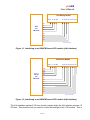
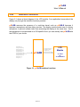
The hardware interface of an LCD module is quite straightforward. LCD modules can
generally interface directly with most microprocessor buses either as an I/O device or a
memory mapped I/O. The HD44780 has a 500 nS (nano-second) access time. Connecting
the LCD module on the microprocessor bus is economical but becomes problematic if the
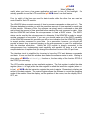
display is located some distance from the microprocessor bus. In this case, parallel I/O
ports can be used to interface with the LCD module, as shown in Figure 1-1 (using a 4-bit
interface) and Figure 1-2 (using an 8-bit interface).
4 of 33
µC/LCD
User’s Manual
LCD Display Module
R/W- E
RS LED
D7 D6 D5 D4 D3 D2 D1 D0
P7
CPU
with
I/O ports
P6
P5
P4
P3
P2
P1
P0
LED = Backlight
Figure 1-1, Interfacing to an HD44780-based LCD module (4-bit interface)
LCD Display Module
R/W- E
RS LED
D7 D6 D5 D4 D3 D2 D1 D0
P11
P10
P9
CPU
with
I/O ports
P8
P7
P6
P5
P4
P3
P2
P1
P0
LED = Backlight
Figure 1-2, Interfacing to an HD44780-based LCD module (8-bit interface)
The 4-bit interface requires 8 I/O lines (mostly outputs) while the 8-bit interface requires 12
I/O lines. This assumes that you want to control the backlight of the LCD module. This is
5 of 33
µC/LCD
User’s Manual
useful when you have a low power application and want to turn off the backlight. It’s
actually possible to read the LCD module but µC/LCD doesn’t use that feature.
Four (or eight) of the lines are used for data transfer while the other four are used as
control lines for the LCD module.
The HD44780 takes a certain amount of time to process commands or data sent to it. The
Renesas datasheet provides you with the maximum amount of time required for each type
of data transfer. Because of this, the software can simply send a command or data and
wait at least the amount of time specified before sending the next command or data. Note
that the HD44780 itself allows the microprocessor to read a BUSY status. The BUSY
status can be read by the microprocessor to determine if the HD44780 is ready to accept
another command or more data. If you can, you should make use of the BUSY capability
of the HD44780 because this provides you with a true indication that the HD44780 is ready
to accept another command or more data. As a precaution, however, you should still
provide a timeout loop to prevent hanging up the microprocessor in case of a malfunction
with the interface electronics. Unless the LCD module is directly connected to the
microprocessor bus, implementing read capability with parallel I/O ports is a bit more
complicated since it requires that you change the direction of some of the I/O port lines.
The interface circuit is simplified by choosing to have the CPU wait between commands
and data. It turns out that this scheme also makes the software easier to write. Waiting is
done using µC/OS-II’s OSTimeDly() function or, the time delay of the function RTOS of
the RTOS you are using.
The LCD module appears as two read/write registers. The first register is called the data
register (when RS is high) while the other register is called the instruction register (when RS
is low). µC/LCD calls the instruction register the control register. Characters to display are
written to the data register. The control register allows the software to control the operating
mode of the module: clear the display, set the position of the cursor, turn the display ON or
OFF, etc.
6 of 33
µC/LCD
User’s Manual
2.00
µC/LCD Internals
The
source
code
for
µC/LCD
is
found
in
the
following
directory:
\Micrium\Software\uC-LCD\Source. The source code is found in files LCD.C and
LCD.H. As a convention, all functions and variables related to the display module start with
Disp while all #define constants start with DISP_.
The code allows you to interface to just about any LCD module based on the Renesas
HD44780 LCD module controller. At first view, you might think that writing a software
module for an LCD module is a trivial task. This is not quite the case because the
HD44780 has its quirks. The HD44780 was originally designed for a 40 characters by 2
lines display (40x2) and thus has internal memory to hold 80 characters. The first 40
characters are stored at memory locations 0x80 through 0xA7 (128 to 167) while the next
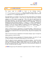
40 characters are stored at memory locations 0xC0 through 0xE7 (192 to 231)! Tables 5.1
through 5.4 show the memory mapping for different LCD module configurations. The
addresses are shown in decimal and are actually based at 0x80. That is, address 00
actually corresponds to 0x80, address 64 is actually 0xC0 (i.e., 0x80 + 64), etc.
Table 2-1 shows the memory organization for 16-character displays. Notice how the 16
characters by 1 line module appears as a two-line display. This is done by the LCD module
manufacturers to reduce the cost of their product by fully using the drive capability of the
HD44780.
Table 2-2 shows the memory organization for 20-character displays. Again, the single-line
display appears as a two-line module.
Table 2-3 shows the memory organization for 24-character displays. As with the 16- and
20-character displays, the single-line display appears as a two-line module.
Table 2-4 shows the memory organization for 40-character displays. As with the other
module configurations, the single-line display appears as a two-line module. Note that
each line of a 40-character display is shown broken down into two separate lines; the
second line is offset from the first. This has been done to avoid reducing the character font
in order to fit within the width of the page.
µC/LCD will support any LCD module that is organized as shown in Table 2-1 through 2-4.
7 of 33
µC/LCD
User’s Manual
16 Characters x 1 line
0
0
0
0
0
0
0
0
6
6
6
6
6
6
7
7
16 Characters x 2 lines
0
0
0
0
0
0
0
0
0
0
1
1
1
1
1
1
6
6
6
6
6
6
7
7
7
7
7
7
7
7
7
7
16 Characters x 4 lines
0
0
0
0
0
0
0
0
0
0
1
1
1
1
1
1
6
6
6
6
6
6
7
7
7
7
7
7
7
7
7
7
1
1
1
1
2
2
2
2
2
2
2
2
2
2
3
3
8
8
8
8
8
8
8
8
8
8
9
9
9
9
9
9
Table 2-1, 16xN LCD modules
20 Characters x 1 line
0
0
0
0
0
0
0
0
0
0
6
6
6
6
6
6
7
7
7
7
20 Characters x 2 lines
0
0
0
0
0
0
0
0
0
0
1
1
1
1
1
1
1
1
1
1
6
6
6
6
6
6
7
7
7
7
7
7
7
7
7
7
8
8
8
8
20 Characters x 4 lines
0
0
0
0
0
0
0
0
0
0
1
1
1
1
1
1
1
1
1
1
6
6
6
6
6
6
7
7
7
7
7
7
7
7
7
7
8
8
8
8
2
2
2
2
2
2
2
2
2
2
3
3
3
3
3
3
3
3
3
3
8
8
8
8
8
8
9
9
9
9
9
9
9
9
9
9
10
10
10
10
1
1
6
6
6
6
6
6
7
7
7
Table 2-2, 20xN LCD modules
24 Characters x 1 line
0
0
0
0
0
0
0
0
0
0
7
7
7
24 Characters x 2 lines
00
0
02
03
04
05
06
07
08
09
10
1
12
13
14
15
16
17
18
19
20
2
22
23
64
65
66
67
68
69
70
7
72
73
74
75
76
77
78
79
80
8
82
83
84
85
86
87
Table 2-3, 24xN LCD modules
8 of 33
µC/LCD
User’s Manual
40 Characters x 1 line
0
0
0
0
0
0
0
0
0
0
1
1
1
1
1
1
1
1
1
1
6
6
6
6
6
6
7
7
7
7
7
7
7
7
7
7
0
0
0
0
0
0
1
1
1
1
1
1
1
1
1
1
2
2
2
2
2
2
2
2
2
2
3
3
3
3
3
3
6
6
7
7
7
7
7
7
7
7
7
7
8
8
8
8
8
8
8
8
8
8
9
9
9
9
9
9
9
9
9
9
8
8
8
8
3
3
3
3
10
10
10
10
40 Characters x 2 lines
0
6
0
6
0
6
0
6
Table 2-4, 40xN LCD modules
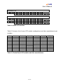
Table 2-5 shows a list of some LCD module configurations and their manufacturer's part
numbers.
#Lines
1
2
4
1
2
4
1
2
1
2
#Characters Densitron P/
16
LM4020
16
LM4222
16
LM4443
20
LM432
20
LM4261
20
LM4821
24
LM413
24
LM4227
40
LM414
40
LM4218
Optrex P/N
DMC16117A
DMC16207
DMC16433
DMC20215
DMC20434
DMC24138
DMC24227
DMC40218
Seiko P/N
M1641
M1632
M1614
L2012
L2014
L2432
L4041
L4042
Stanley P/N
GMD1610
GMD1620
GMD1640
GMD2020
GMD2040
GMD2420
GMD4020
Table 2-5, Partial list of LCD modules and their manufacturers
9 of 33
FEMA P/N
MDL1611
MDL1621
MDL2021
MDL2041
MDL2411
MDL2421
MDL4011
MDL4021
µC/LCD
User’s Manual
3.00
Interface Functions
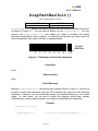
Figure 2-1 shows a block diagram of the LCD module. Your application knows about the
display only through the interface functions provided.
µC/LCD assumes the presence of a real-time kernel such as µC/OS-II because it
requires a semaphore and time delay services. The display module makes use of a binary
semaphore to prevent multiple tasks from accessing the display at the same time. Use of
the semaphore is encapsulated in an OS specific file so you can actually use µC/LCD with
the RTOS of your choice.
DispChar()
DispClrLine()
DispClrScr()
DispDefChar()
DispHorBar()
DispHorBarInit()
DispVertBarInit()
DispVertBar()
DispInit()
DispStr()
µC/LCD
LCD
Module
DispInitPort()
DispDataWr()
DispSel()
‘n’ Lines
by
‘m’ characters
Figure 3-1, µC/LCD interface functions
10 of 33
µC/LCD
User’s Manual
DispChar()
void DispChar(INT8U row, INT8U col, INT8U c);
File
Called from
LCD.C
Application Code
DispChar() allows you to display a single character anywhere on the display.
Arguments
row and col
specifies the coordinates (row, col) where the character will appear. rows
(i.e., lines) are numbered from 0 to DispMaxRows – 1, and columns
are numbered from 0 to DispMaxCols – 1.
c
is the character to display. The HD44780 allows you to specify up to eight
characters or symbols numbered from 0 to 7 (i.e., its identification). You
display a user-defined character or symbol by calling DispChar(), the
row/column position, and the character or symbol's identification number.
Returned Value
None
Notes/Warnings
None
Example
void Task (void *p_arg)
{
.
.
for (;;) {
.
DispChar(1, 3, ‘$’); /* Display ‘$’ on 2nd row, 4th character */
.
.
}
}
11 of 33
µC/LCD
User’s Manual
DispClrLine()
void DispClrLine(INT8U line)
File
Called from
LCD.C
Application Code
DispClrLine() allows your application to clear one of the LCD module's lines. The line
is basically filled with the ASCII character ‘ ‘ (i.e. 0x20).
Arguments
line is the line (i.e., row) to clear. Note that lines are numbered from 0 to DispMaxRows –
1.
Returned Value
None
Notes/Warnings
None
Example
void Task (void *p_arg)
{
.
.
for (;;) {
.
DispClrLine(0);
.
.
}
}
/* Clear the first line of the display */
12 of 33
µC/LCD
User’s Manual
DispClrScr()
void DispClrScr(void)
File
Called from
LCD.C
Application Code
DispClrScr() allows you to clear the screen. The cursor is positioned on the top leftmost
character. The screen is basically filled with the ASCII character ‘ ‘ (i.e. 0x20).
Arguments
None
Returned Value
None
Notes/Warnings
None
Example
void Task (void *p_arg)
{
.
.
for (;;) {
.
DispClrScr();
.
.
}
}
/* Clear everything on the display */
13 of 33
µC/LCD
User’s Manual
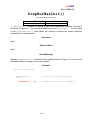
DispDefChar()
void DispDefChar(INT8U id, INT8U *pat)
File
Called from
LCD.C
Application Code
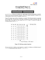
DispDefChar() allows you to define up to eight custom 5x8 pixel characters or symbols.
This is one of the most powerful features of the LCD modules because it allows you to
create graphics such as icons, bar graphs, arrows, etc.
Figure 3-2 shows how to define a character or a symbol. The 5x8 pixel matrix is organized
as a bitmap table. The first entry of the table corresponds to pixels for the first row, the
second entry, the pixels for the second row, etc. A pixel is turned ON when its
corresponding bit is set (i.e., 1).
Figure 3-2, Defining custom characters
All you need to do to define a new character or symbol is to declare an initialized array of
INT8Us containing eight entries and call DispDefChar().
14 of 33
µC/LCD
User’s Manual
Arguments
id
specifies an identification number for the new character or symbol (a
number between 0 and 7). The identification number will be used to
actually display the new character or symbol.
pat
is a pointer to the bitmap table which defines what the character or symbol
will look like.
Returned Value
None
Notes/Warnings
None
Example
const INT8U DispRightArrowChar[] = {
0x08, 0x0C, 0x0E, 0x1F, 0x1F, 0x0E, 0x0C, 0x08
};
void Task (void *pdata)
{
.
.
for (;;) {
.
DispDefChar(0, &DispRightArrowChar[0]); /* Define arrow char. */
.
.
}
}
Figure 3-3 shows examples of bitmaps to create arrows and other symbols. Once symbols
are created, you can display them by calling DispChar() .
15 of 33
µC/LCD
User’s Manual
Figure 3-3, Examples of custom symbols
16 of 33
µC/LCD
User’s Manual
DispHorBar()
void DispHorBar(INT8U row, INT8U col, INT8U val)
File
Called from
LCD.C
Application Code
You can use µC/LCD to create remarkably high quality bargraphs. The linear bargraph is
an excellent trend indicator and can greatly enhance operator feedback. Depending on the
size of the module, many bargraphs can be simultaneously displayed. µC/LCD allows you
to display bar graphs of any size anywhere on the screen.
DispHorBar() is used to display horizontal bars anywhere on the screen.
Figure 3-4 also shows that a 16xN-character display can produce bar graphs with up to 80
bars (16 x 5 bars per character block). In Figure 3-4, we started the bar graph on the first
column on a 16xN-character display. Once scaled, bar graphs can represent just about
anything. For example, the 38 bars shown in Figure 3-4 can represent 47.5 percent (38
bars = 47.5/100 x 80), 100.7 degrees if the bar graph is used to represent temperatures
from 0 to 212 degrees, etc.
Figure 3-4, Bargraphs with 16-character displays
17 of 33
µC/LCD
User’s Manual
Arguments
row and col
Specifies the coordinates (row, col) where the first character in the
bargraph will appear. rows (i.e., lines) are numbered from 0 to
DispMaxRows –
1, and columns are numbered from 0 to
DispMaxCols – 1.
val
is the number of bars you want to have turned on (a number between 0 to
80 in this example). On a 20 character display, you can have up to 100
bars.
Returned Value
None
Notes/Warnings
Before you can use DispHorBar(), you MUST call DispHorBarInit() which defines 5
characters used for bargraphs.
Example
You could actually use fewer bars and display the actual value next to the bar graph, as
shown in Figure 3-5. In this example, I am displaying 100.7 degrees (28 bars) on a scale of
0 to 212 degrees (60 bars).
Figure 3-5, Bargraph with Value
void Task (void *pdata)
{
.
.
for (;;) {
.
DispHorBar(0, 4, 28);
.
.
}
}
/* Display a 28 out of 60 bars */
18 of 33
µC/LCD
User’s Manual
DispHorBarInit()
void DispHorBarInit(void)
File
Called from
LCD.C
Application Code
DispHorBarInit() defines five special symbols with identification numbers 1 through 5
as shown in Figure 3-4. You must be call before you use DispHorBar(). You only need
to call DispHorBarInit() once unless you intend to re-define the symbol identifiers
dynamically for other purposes.
Arguments
None
Returned Value
None
Notes/Warnings
Because DispHorBarInit() defines the five symbols shown in Figure 3-4, you must use
other identification numbers for your own symbols.
Example
void Task (void *p_arg)
{
.
.
DispHorBarInit();
for (;;) {
.
DispHorBar(0, 4, 28);
.
.
}
}
/* Initialize the bargraph capability
*/
/* Display a 28 out of 60 bar bargraph */
19 of 33
µC/LCD
User’s Manual
DispInit()
void DispInit(INT8U maxrows, INT8U maxcols)
File
Called from
LCD.C
Application Code
DispInit() is the initialization code for the module and must be invoked before any of
the other functions. DispInit() assumes the presense of a real-time kernel such as
µC/OS-II since it uses services provided by the kernel.
DispInit() initializes the hardware, creates a semaphore, and sets the operating mode
of the LCD module.
Arguments
maxrows
is the LCD module's maximum number of rows (lines), and maxcols is
the maximum number of columns (characters per line).
Returned Value
None
Notes/Warnings
None
Example
You should call DispInit() from your user interface task (assuming you have a 4x20
display) as follows:
void UserIFTask (void *p_arg)
{
DispInit(4, 20);
/* Initialize the 4x20 LCD display */
for (;;) {
.
.
User interface code;
.
.
}
}
20 of 33
µC/LCD
User’s Manual
DispStr()
void DispStr(INT8U row, INT8U col, INT8U *s)
File
Called from
LCD.C
Application Code
DispStr() allows you to display ASCII strings anywhere on the display. You can easily
display either integer or floating-point numbers using the standard library functions
itoa(), ltoa(), sprintf(), etc. Of course, you should ensure that these functions are
reentrant if you are using them in a multitasking environment.
Arguments
row and col
will specify the coordinates (row, col) where the first character of the ASCII
string will appear. Note that rows (i.e., lines) are numbered from 0 to
DispMaxRows –
1. Similarly, columns are numbered from 0 to
DispMaxCols – 1. The upper-left corner is coordinate 0, 0.
s
is the ASCII string. The displayed string will be truncated if the string is
longer than the available space on the specified line.
Returned Value
NONE
Notes/Warnings
NONE
Example
void UserIFTask (void *data)
{
DispInit(4, 20);
/* Initialize the 4x20 LCD display */
for (;;) {
.
.
DispStr(0, 0, “Hello World”);
.
.
}
}
21 of 33
µC/LCD
User’s Manual
DispVertBar()
void DispVertBar(INT8U row, INT8U col, INT8U val)
File
Called from
LCD.C
Application Code
You can use µC/LCD to create remarkably high quality bargraphs. The linear bargraph is
an excellent trend indicator and can greatly enhance operator feedback. Vertical bargraphs
can be used to display histograms, audio levels, tank levels, temperature levels, etc.
Depending on the size of the module, many bargraphs can be simultaneously displayed.
µC/LCD allows you to display bar graphs of any size anywhere on the screen.
DispVerBar() is used to display horizontal bars anywhere on the screen.
Figure 3-6 also shows that a 16x2-character display can produce bar graphs with up to 16
vertical bars (using 2 characters high). In Figure 3-6, we started the bar graph on the 7th
column leaving 6 characters on each line for other information (the name of the graph or
other).
16
Bars
Figure 3-6, Bargraphs with 16x2 character displays
Arguments
row and col
Specifies the coordinates (row, col) where the first character in the
bargraph will appear. rows (i.e., lines) are numbered from 0 to
DispMaxRows –
1, and columns are numbered from 0 to
DispMaxCols – 1.
val
is the number of vertical bars you want to have turned on (a number
between 0 to 8 in this example). Note that in Figure 3-6, we actually used
two vertical characters to ‘extend’ the height of the bargraph.
Returned Value
None
22 of 33
µC/LCD
User’s Manual
Notes/Warnings
Before you can use DispVertBar(), you MUST call DispVertBarInit() which
defines 8 characters used for bargraphs (see the description of DispVertBarInit()).
Example
The code below shows how we displayed the bars in Figure 3-6. Here, we assume that
your application code filled the table VertBarTbl[] with the desired values to display.
Each entry in the table needs to be a number between 0 and 16, inclusively. A higher
value would display only 16 bars.
INT8U
VertBarTbl[10];
void Task (void *pdata)
{
.
.
for (;;) {
.
for (i = 0; i < 10; i++) {
if (VertBarTbl[i] > 8)
DispVertBar(0, i +
DispVertBar(1, i +
} else {
DispVertBar(0, i +
}
}
.
.
}
}
{
6, VertBarTbl[i] – 8);
6, 8);
6, VertBarTbl[i]);
23 of 33
µC/LCD
User’s Manual
DispVertBarInit()
void DispVertBarInit(void)
File
Called from
LCD.C
Application Code
DispVertBarInit() defines five special symbols with identification numbers 0 through 7
as shown in Figure 3-7. You must be call before you use DispVertBar(). You only
need to call DispVertBarInit() once unless you intend to re-define the symbol
identifiers dynamically for other purposes. You should note that there the ‘blank’ value of 0
bars corresponds to the ‘space’ and thus, is already defined.
Symbol
Identifiers
0
1
2
3
4
5
6
7
Figure 3-7, Definition of Vertical Bar characters
Arguments
None
Returned Value
None
Notes/Warnings
Because DispVertBarInit() defines the eigth symbols shown in Figure 3-7, you will not
be able to create other characters since the LCD controller only supports 8 user definable
characters. However, you can dynamically change the characters based on your screen
usage. In other words, you can have a screen that displays vertical bars, another
horizontal bars, another special symbols, etc. simply by redefining these characters.
Example
void Task (void *p_arg)
{
:
DispVertBarInit();
:
}
/* Initialize the bargraph capability
24 of 33
*/
µC/LCD
User’s Manual
4.00
µC/LCD Configuration
4.01
DISP_BUS_WIDTH
You need to set the value of one #define constant: DISP_BUS_WIDTH. This #define
needs to be placed in YOUR application header file which gets included when you compile
LCD.C. Specifically, LCD.C assumes the presence of a header file called ‘includes.h’
that is assumed to reside in your application directory.
You can thus place
DISP_BUS_WIDTH in this file if you want. We typically like to place all application
configuration #defines in a file called APP_CFG.H which gets #included in includes.h.
DISP_BUS_WIDTH determines whether you have a 4-bit or 8-bit interface to the LCD
module. µC/LCD needs to know this in order to send the proper initialization commands to
the LCD controller. You MUST set DISP_BUS_WIDTH to either 4 or 8.
4.02
Hardware interface functions
To make µC/LCD as portable as possible, access to hardware ports has been
encapsulated into the following functions:
DispDataWr()
DispDly_uS()
DispInitPort()
DispSel()
These functions are described in the following pages.
25 of 33
µC/LCD
User’s Manual
DispDataWr()
void DispDataWr(INT8U data)
File
Called from
BSP.C
LCD.C
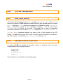
DispDataWr() is used to write a single byte to the LCD module. Depending on the state
of the RS line (see Figure 1-1 and 1-2), the byte will be either sent to the data (RS is 1) or
control register (RS is 0) of the LCD controller.
Arguments
data
is the byte value to write to the LCD controller module. The destination
‘inside’ the HD44780 depends on whether RS is high or low.
Returned Value
None
Notes/Warnings
None
Example assuming a 4-bit interface
void DispDataWr (INT8U data)
{
/* Set R/W
control line
/* Set the E control line
/* Write the UPPER nibble
/* Delay for about 100 µS
/* Set the E control line
/* Delay for about 100 µS
/* Set the E control line
/* Write the LOWER nibble
/* Delay for about 100 µS
/* Set the E control line
}
LOW to write to the LCD module
HIGH
of ‘data’ to D7..D4
LOW
HIGH
of ‘data’ to D7..D4
LOW
26 of 33
*/
*/
*/
*/
*/
*/
*/
*/
*/
*/
µC/LCD
User’s Manual
Example assuming an 8-bit interface
void DispDataWr (INT8U data)
{
/* Set R/W
control line LOW to write to the LCD module
/* Set the E control line HIGH
/* Write the ‘data’ to D7..D0
/* Delay for about 100 µS
/* Set the E control line LOW
}
27 of 33
*/
*/
*/
*/
*/
µC/LCD
User’s Manual
DispDly_uS()
void DispDly_uS(INT32U us)
File
Called from
BSP.C
LCD.C and BSP.C
DispDly_uS() allows the code to delay for the execution for a certain amount of time to
allow the data to ‘stabilize’ and for the HD44780 to complete it’s operation. The delay is
specified in microseconds (µS). This operation is easy to perform if you have a real-time
kernel such as µC/OS-II.
Arguments
determines the amount of delay (in microseconds).
us
Returned Value
None
Notes/Warnings
None
Example using µC/OS-II
void DispDly_uS (INT32U us)
{
INT32U us_per_tick;
INT32U ticks;
us_per_tick = 1000000L / OS_TICKS_PER_SEC;
ticks
= us / us_per_tick + 1;
OSTimeDly(ticks);
}
28 of 33
µC/LCD
User’s Manual
DispInitPort()
void DispInitPort(void)
File
Called from
BSP.C
DispInit()
DispInitPort() is responsible for initializing the hardware used to interface with the
LCD module. DispInitPort() is called by DispInit().
Arguments
None
Returned Value
None
Notes/Warnings
None
Example
void DispInitPort (void)
{
/* Setup RS, E and R/W lines as outputs
*/
/* Setup the Data Lines to the LCD module as outputs */
}
29 of 33
µC/LCD
User’s Manual
DispSel()
void DispSel(INT8U sel)
File
Called from
BSP.C
LCD.C
DispSel() determines whether data written to the HD44780 goes to the control or data
register.
Arguments
sel
determines whether data written using DispDataWr() goes to the
command register (when sel == DISP_SEL_CMD_REG) or the data
register (when sel == DISP_SEL_DATA_REG).
Returned Value
None
Notes/Warnings
None
Example
void DispSel (INT8U sel)
{
if (sel == DISP_SEL_CMD_REG) {
/* Set the RS control line LOW
} else {
/* Set the RS control line HIGH
}
}
30 of 33
*/
*/
µC/LCD
User’s Manual
5.00
RTOS Interface
µC/LCD assumes the presence of an RTOS to make the code ‘thread safe’. This means
that you can invoke µC/LCD functions from multiple tasks in a multitasking environment.
µC/LCD only requires semaphore services or its equivalent.
The RTOS interface functions have been encapsulated in a file called LCD_OS.C. The
RTOS interface functions for µC/OS-II is found in:
\Micrium\Software\uC-LCD\OS\uCOS-II
If you need to interface µC/LCD to a different RTOS, you can create your own version of
LCD_OS.C for that RTOS.
The interface functions for µC/OS-II are shown below:
static OS_EVENT *DispSem;
/* Semaphore used to access display */
void DispInitOS (void)
{
DispSem = OSSemCreate(1);
/* Create display access semaphore
*/
/* Obtain exclusive access to the display
OSSemPend(DispSem, 0, &err);
*/
}
void DispLock (void)
{
INT8U err;
}
void DispUnlock (void)
{
OSSemPost(DispSem);
}
/* Release access to display
31 of 33
*/
µC/LCD
User’s Manual
References
µC/OS-II, The Real-Time Kernel, 2nd Edition
Jean J. Labrosse
R&D Technical Books, 2002
ISBN 1-5782-0103-9
Contacts
Micriµm
949 Crestview Circle
Weston, FL 33327
USA
+1 954 217 2036
+1 954 217 2037 (FAX)
e-mail:
[email protected]
WEB: www.Micrium.com
CMP Books, Inc.
1601 W. 23rd St., Suite 200
Lawrence, KS 66046-9950
USA
+1 785 841 1631
+1 785 841 2624 (FAX)
WEB: http://www.rdbooks.com
e-mail:
[email protected]
Densitron Corporation
2039 HW 11
Camden, SC 29020
(803) 432-5008
Hitachi America, Ltd.
Electron Tube Division
3850 Holcomd Bridge Rd.
Norcross, GA 30092
(404) 409-3000
32 of 33
µC/LCD
User’s Manual
Optrex Corp.
23399-T Commerce Drive
Suite B-8
Farmington Hills, MI 48335
(313) 471-6220
Seiko Instruments USA, Inc.
Electronic Components Division
2990 West Lomita Blvd.
Torrance, CA 90505
(310) 517-7829
Stanley Electric
2660 Barranca Parkway
Irvine, CA 92714
(714) 222-0777
33 of 33


![Hacking Medical Devices - [media.blackhat.com]](http://vs1.manualzilla.com/store/data/005931227_1-f7547ce2b3ff0825b843d9b1dbb48800-150x150.png)