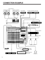
1
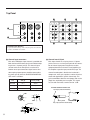
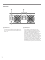
Powered Mixer
Tables de mixage á amplification de puissance
Aktiv-Mischpult
Operation Manual
Manuel d'instructions
Bedienungsanleitung
CD IN
-6dB
A
EFFECT RETURN +4dB
B
L
L
1L/
MONO
2L/
MONO
R
R
1R
2R
INPUT
A
A
REC OUT
-10dBV
BALANCED
B
B
L
R
R
L
R
PRE GEQ
CH
INSERT I/O
0dB
I/O
2
1
3
5
4
6
7
8
9
10
11
12
13
14
15
1
2
LINE INSERT I/O +4dB
TAPE IN
-10dBV
L
EFFECT SEND +4dB
MONITOR OUT +4dB
L
A
R
B
POST GEQ
INSERT
16
OUT IN
L
1
2
3
4
5
6
7
8
9
10
11
12
13
14
15
A
B
A
B
A
B
A
B
A
B
A
B
A
B
A
B
A
B
A
B
A
B
A
B
A
B
A
B
A
B
A
B
PAD
20dB
PAD
20dB
PAD
20dB
PAD
20dB
PAD
20dB
PAD
20dB
PAD
20dB
PAD
20dB
PAD
20dB
PAD
20dB
PAD
20dB
PAD
20dB
PAD
20dB
PAD
20dB
PAD
20dB
PAD
20dB
VOCAL
PEAK
PEAK
PEAK
PEAK
PEAK
PEAK
PEAK
PEAK
PEAK
PEAK
PEAK
PEAK
PEAK
PEAK
PEAK
PEAK
SIGNAL
SIGNAL
SIGNAL
SIGNAL
SIGNAL
SIGNAL
SIGNAL
SIGNAL
SIGNAL
SIGNAL
SIGNAL
SIGNAL
SIGNAL
SIGNAL
SIGNAL
SIGNAL
-16
GAIN
-60
-16
+15
-15
GAIN
-60
-16
+15
-15
80
80
GAIN
-60
-16
+15
-15
80
GAIN
-60
-16
+15
-15
80
GAIN
-60
-16
+15
-15
80
GAIN
-60
-16
+15
-15
80
GAIN
-60
-16
+15
-15
80
GAIN
-60
-16
+15
-15
80
GAIN
-60
-16
+15
-15
80
GAIN
-60
-16
+15
-15
80
GAIN
-60
-16
+15
-15
80
GAIN
-60
-16
+15
-15
80
GAIN
-60
-16
+15
-15
80
GAIN
-60
-16
+15
-15
80
GAIN
ST
R
16
-60
-16
+15
-15
80
GAIN
HALL/ROOM
INSTRUMENT
LARGE HALL
REV (s)
SHARE GATE
DLY (ms)
SMALL HALL
REV (s)
SHARE REVERB
REV (s)
REV (s)
CHURCH
REV (s)
DELAY L, R
DLY (ms)
VOCAL REVERB 2
REV (s)
ROOM
SIZE
REVERB & ECHO 1
DLY (ms)
REVERB & ECHO 2
DLY (ms)
VOCAL ECHO 1
DLY (ms)
VOCAL ECHO 2
DLY (ms)
VOCAL REVERB 1
SHORT DELAY
DLY (ms)
PITCH CHORUS
DETUNE
PEAK
-60
ON
80
PRESET
PARAMETER
PROGRAM
RESET
DIGITAL EFFECT (EFFECT 2)
-15
HIGH
HIGH
HIGH
HIGH
HIGH
HIGH
HIGH
HIGH
HIGH
HIGH
HIGH
HIGH
HIGH
HIGH
HIGH
HIGH
+15
250
5k
MID FREQ
250
5k
MID FREQ
250
5k
MID FREQ
250
5k
MID FREQ
250
5k
MID FREQ
250
5k
MID FREQ
250
5k
MID FREQ
250
5k
MID FREQ
250
5k
MID FREQ
250
5k
MID FREQ
250
5k
MID FREQ
250
5k
MID FREQ
250
5k
MID FREQ
250
5k
MID FREQ
250
5k
MID FREQ
250
5k
MID FREQ
-15
+15
-15
+15
-15
+15
-15
+15
-15
+15
-15
+15
-15
+15
-15
+15
-15
+15
-15
+15
-15
+15
-15
+15
-15
+15
-15
+15
-15
+15
-15
+15
-15
+15
-15
+15
-15
+15
-15
+15
-15
+15
-15
+15
-15
+15
-15
+15
-15
+15
-15
+15
-15
+15
-15
+15
-15
+15
-15
+15
-15
-15
MID
LOW
MID
LOW
MID
LOW
MID
LOW
MID
LOW
MID
LOW
MID
LOW
MID
LOW
MID
LOW
MID
LOW
MID
LOW
MID
LOW
MID
LOW
MID
LOW
MID
LOW
MID
LOW
EQ
+12
9
6
3
0
3
6
9
-12
+12
9
6
3
0
3
6
9
-12
63
+15
125
250
500
1k
2k
4k
8k
16k
STEREO GRAPHIC EQUALIZER
+15
0
10
MONITOR
0
10
MONITOR
0
10
MONITOR
0
10
MONITOR
0
10
MONITOR
0
10
MONITOR
0
10
MONITOR
0
10
MONITOR
0
10
MONITOR
0
10
MONITOR
0
10
MONITOR
0
10
MONITOR
0
10
MONITOR
0
10
MONITOR
0
10
MONITOR
0
10
MONITOR
0
10
EFFECT 1
0
10
EFFECT 1
0
10
EFFECT 1
0
10
EFFECT 1
0
10
EFFECT 1
0
10
EFFECT 1
0
10
EFFECT 1
0
10
EFFECT 1
0
10
EFFECT 1
0
10
EFFECT 1
0
10
EFFECT 1
0
10
EFFECT 1
0
10
EFFECT 1
0
10
EFFECT 1
0
10
EFFECT 1
0
10
EFFECT 1
0
10
EFFECT 2
0
10
EFFECT 2
0
10
EFFECT 2
0
10
EFFECT 2
0
10
EFFECT 2
0
10
EFFECT 2
0
10
EFFECT 2
0
10
EFFECT 2
0
10
EFFECT 2
0
10
EFFECT 2
0
10
EFFECT 2
0
10
EFFECT 2
0
10
EFFECT 2
0
10
EFFECT 2
0
10
EFFECT 2
0
10
EFFECT 2
L
L
L
L
L
L
L
L
L
L
L
L
L
L
L
L
POWERED MIXER
PHANTOM
ON
OFF
R
1
R
PAN
PAN
R
PAN
ON
ON
R
PAN
ON
R
PAN
ON
R
PAN
ON
R
PAN
ON
R
PAN
ON
R
PAN
ON
R
PAN
ON
R
PAN
ON
R
PAN
ON
R
PAN
ON
R
PAN
ON
R
PAN
ON
0
10
MONITOR
R
0
PAN
ON
ON
10
0
10
MONITOR
0
10
MONITOR A
0
0
10
MONITOR B
10
LEVEL
LEVEL
EFFECT RETURN 1
EFFECT RETURN 2
0
10
REC OUT
0
0
10
TAPE IN
10
CD IN
A
B
0
0
0
0
0
0
0
0
0
0
0
0
0
0
0
0
0
0
0
0
5
5
5
5
5
5
5
5
5
5
5
5
5
5
5
5
5
5
5
5
10
10
10
10
10
10
10
10
10
10
10
10
10
10
10
10
10
10
10
10
15
15
15
15
15
15
15
15
15
15
15
15
15
15
15
15
15
15
15
15
20
20
20
20
20
20
20
20
20
20
20
20
20
20
20
20
20
20
20
20
30
30
30
30
30
30
30
30
30
30
30
30
30
30
30
30
30
30
30
30
40
40
40
40
40
40
40
40
40
40
40
40
40
40
40
40
40
40
40
40
50
60
50
60
50
60
50
60
50
60
50
60
50
60
50
60
50
60
50
60
50
60
50
60
50
60
50
60
50
60
50
60
50
60
50
60
50
60
50
60
2
3
4
5
6
7
8
9
10
11
12
13
14
15
16
1—EFFECT SEND—2
L
ST
R
0
10
PHONES
PHONES
EMX3500m R0 1 AP
Printed in Korea
P.O. Box 1, Hamamatsu, Japan
CONGRATULATIONS!
Your Yamaha EMX3500 Powered Mixer is an ideal choice for medium-scale PA and sound reinforcement applications. The
EMX3500 is available in 12- and 16-channel models, each of which features a high-performance stereo power amplifier that
delivers a powerful 350 watts per channel into 4-ohm loads.
Each input channel offers a choice of balanced low-impedance XLR or TRS phone jack inputs, and a 20-dB pad switch and
input gain control allow precise level matching with any input source. The response of each channel signal can be independently shaped by a three-band equalizer with variable mid-range frequency. Also, each channel has dual EFFECT controls
and a MONITOR control that make possible convenient incorporation of external effects and monitoring systems, and a PAN
control that can be used to pan the channel signal across the master stereo bus.
The EFFECT 2 control also feeds the EMX3500’s internal effects processor, which is one of the highlights of the EMX series.
This sophisticated Yamaha digital signal processor provides 15 top-quality digital effects, each of which has a programmable
parameter that can be adjusted to create precisely the required sound.
In addition to the internal DSP controls, the EMX3500’s master control section includes: a nine-band stereo graphic equalizer that allows overall output response shaping and feedback control in sound reinforcement applications; paired master
stereo faders; master EFFECT SEND faders; and EFFECT RETURN controls, which allow the returned effect signals to be
sent to the monitor system as well as the stereo bus. There are separate level controls for the dual monitor outputs, and a
level control for headphone output. Finally, there are level controls for input from and output to a recording tape deck, and a
level control for two pairs of selectable CD IN jacks that allow input from CD players or similar sound sources.
In addition to line-insert I/O jacks for each channel, the EMX3500 offers both pre-GEQ and post-GEQ line insertion to the
master stereo bus. These connectors, when combined with the dual effects circuits, give the EMX3500 a formidable degree
of signal-processing versatility. In addition, +48V phantom power is provided for convenient powering of condenser microphones.
We urge you to read this operation manual thoroughly in order to get the best performance out of the mixer’s many features
and controls. Please keep the manual in a safe place for later reference.
FCC INFORMATION (U.S.A.)
1. IMPORTANT NOTICE: DO NOT MODIFY THIS UNIT!
This product, when installed as indicated in the instructions contained in this manual, meets FCC requirements. Modifications not expressly approved by Yamaha
may void your authority, granted by the FCC, to use the product.
2. IMPORTANT: When connecting this product to accessories and/or another product use only high quality shielded cables. Cable/s supplied with this product MUST
be used. Follow all installation instructions. Failure to follow instructions could void your FCC authorization to use this product in the USA.
3. NOTE: This product has been tested and found to comply with the requirements listed in FCC Regulations, Part 15 for Class "B" digital devices. Compliance with
these requirements provides a reasonable level of assurance that your use of this product in a residential environment will not result in harmful interference with other
electronic devices. This equipment generates/uses radio frequencies and, if not installed and used according to the instructions found in the users manual, may cause
interference harmful to the operation of other electronic devices. Compliance with FCC regulations does not guarantee that interference will not occur in all
installations. If this product is found to be the source of interference, which can be determined by turning the unit "OFF" and "ON", please try to eliminate the problem
by using one of the following measures:
Relocate either this product or the device that is being affected by the interference.
Utilize power outlets that are on different branch (circuit breaker of fuse) circuits or install AC line filter/s.
In the case of radio or TV interference, relocate/reorient the antenna. If the antenna lead-in is 300 ohm ribbon lead, change the lead-in to coaxial type cable.
If these corrective measures do not produce satisfactory results, please contact the local retailer authorized to distribute this type of product. If you can not locate the
appropriate retailer, please contact Yamaha Corporation of America, Electronic Service Division, 6600 Orangethorpe Ave, Buena Park, CA 90620
* This applies only to products distributed by YAMAHA CORPORATION OF AMERICA.
IMPORTANT NOTICE FOR
THE UNITED KINGDOM
Connecting the Plug and Cord
WARNING: THIS APPARATUS MUST BE EARTHED
IMPORTANT: The wires in this mains lead are coloured in accordance with
the following code:
GREEN-AND-YELLOW : EARTH
BLUE
: NEUTRAL
ADVARSEL!
Lithiumbatteri–Eksplosionsfare ved fejlagtig håndtering.
Udskiftning må kun ske med batteri af samme fabrikat og type.
Levér det brugte batteri tilbage til leverandoren.
VARNING
Explosionsfara vid felaktigt batteribyte. Använd samma batterityp
eller en ekvivalent typ som rekommenderas av apparattillverkaren.
Kassera använt batteri enligt fabrikantens instruktion.
BROWN: LIVE
As the colours of the wires in the mains lead of this apparatus may not
correspond with the coloured markings identifying the terminals in your plug,
proceed as follows:
The wire which is coloured GREEN and YELLOW must be connected to the
VAROITUS
Paristo voi räjähtää, jos se on virheellisesti asennettu. Vaihda
paristo ainoastaan laitevalmistajan suosittelemaan tyyppiin. Hävitä
käytetty paristo valmistajan ohjeiden mukaisesti.
terminal in the plug which is marked by the letter E or by the safety earth
symbol or coloured GREEN and YELLOW.
The wire which is coloured BLUE must be connected to the terminal which is
marked with the letter N or coloured BLACK.
The wire which is coloured BROWN must be connected to the terminal which
is marked with the letter L or coloured RED.
* This applies only to products distributed by YAMAHA KEMBLE
MUSIC (U.K.) LTD.
1
CONTENTS
PRECAUTIONS ...............................................................................................................3
CONTROLS AND CONNECTORS ..................................................................................4
Front Panel: Input Channel Controls ..........................................................................4
Front Panel: Master Control Section ...........................................................................6
Top Panel ...................................................................................................................8
Rear Panel ...............................................................................................................10
OPERATING TIPS .........................................................................................................11
Cautions for Connected Sources ..............................................................................11
Matching Input Levels ...............................................................................................11
Setting Channel and Master Faders .........................................................................11
Using the Channel Equalizers ..................................................................................12
Using the Digital Signal Processor ...........................................................................12
Using the Graphic Equalizer .....................................................................................13
Connecting Speakers ...............................................................................................13
CONNECTION EXAMPLE .............................................................................................14
SPECIFICATIONS .........................................................................................................15
Input Characteristics .................................................................................................16
Output Characteristics ..............................................................................................16
Console Dimensions ................................................................................................17
BLOCK AND LEVEL DIAGRAMS ..................................................................................18
2
PRECAUTIONS
Please keep the following points in mind when installing and operating your Yamaha EMX3500 Powered Mixer. Also be sure
to read the precautions in the Operating Tips section before using the EMX3500.
• AVOID EXCESSIVE HEAT, HUMIDITY, DUST, AND VIBRATION
Keep the EMX3500 away from locations (such as near radiators, stoves, etc.) where it is likely to be exposed to high
temperatures or humidity. Also avoid locations where the mixer may be exposed to excessive dust accumulation or
vibration that could cause mechanical damage.
• INSTALL IN A WELL-VENTILATED LOCATION
The internal circuitry of the EMX3500 produces heat that can become a potential fire hazard if not properly ventilated.
When setting up the EMX3500 for operation, be sure to leave at least 10 cm between it and any adjacent walls or surrounding equipment.
• AVOID PHYSICAL SHOCKS
Do not drop the EMX3500 or subject it other strong physical shocks, as doing so can damage the it. Handle the mixer with
care, and transport it in a suitable hard case or flight case.
• DO NOT OPEN THE UNIT OR ATTEMPT REPAIRS OR MODIFICATIONS YOURSELF
The EMX3500 contains no user-serviceable parts. Refer all maintenance and repairs to qualified Yamaha service personnel. Opening the case and/or tampering with the internal circuitry will void the warranty.
• MAKE SURE THE POWER IS OFF BEFORE MAKING OR REMOVING CONNECTIONS
Always turn the power OFF before connecting or disconnecting cables. If you insert or remove cables with the power on,
you run the risk of damaging both the mixer and any connected equipment.
• HANDLE CABLES CAREFULLY
Always plug and unplug cables (including the AC power cable) by gripping the connector, not the cord itself.
• CLEAN WITH A SOFT, DRY CLOTH
Never use solvents such as benzine or thinner to clean the EMX3500. Should the mixer become dirty, wipe it clean with a
soft, dry cloth.
• ALWAYS USE THE CORRECT POWER SOURCE
Make sure that the power requirements on the rear panel of the EMX3500 match your local AC mains supply.
• KEEP SPEAKER PLUGS CLEAN
Solid phone plugs can overheat when inserted in the rear-panel SPEAKER jacks of the EMX3500, causing a potential fire
hazard. Make a habit of checking the metal tips of your speaker plugs, and cleaning them if necessary, before connecting
them to the EMX3500.
3
CONTROLS AND CONNECTORS
Front Panel: Input Channel Controls
1 Input selector switch
This switch selects the input connector via which the
source is connected to the channel. Leave the switch
out if the source is connected via the A (balanced XLR)
input connector. Push it in when the source is connected via the B (balanced 1/4" phone) connector.
16
1
2
A
B
PAD
20dB
PEAK
3
SIGNAL
4
-16
GAIN
HIGH
+15
250
5k
MID FREQ
-15
-15
MID
LOW
This switch attenuates the signal applied to channel (at
the corresponding A input connector or B input jack on
the top panel) by 20 dB prior to the head amplifier and
input gain control. This feature can be used to prevent
high-level signals from overloading the input circuitry,
allowing the mixer to handle a wider range of input
signal levels.
5
80
-15
2 PAD switch
-60
6
3 SIGNAL and PEAK LED indicators
+15
These two LED indicators let you check the level of the
signal input to the channel. The green SIGNAL indicator lights when a signal of 10 dB below the nominal
channel level is received. The red PEAK indicator lights
when the input signal reaches 3 dB below the
channel’s clipping point. Both of these indicators show
the level of the post-EQ/pre-fader signal. If the PEAK
indicator lights more than briefly on high-level transients, you should use the PAD switch or the GAIN
control to decrease the input sensitivity of the channel.
If this does not work, reduce the output level of the
connected source.
+15
7
0
10
MONITOR
8
0
10
EFFECT 1
9
0
10
EFFECT 2
0
L
R
PAN
A
ON
4 GAIN control
This control adjusts the channel’s input sensitivity
between –60 dB and –16 dB when the PAD switch is
off, or between –40 dB and +4 dB when the PAD
switch is on. Continuously variable gain control allows
optimum adjustment to virtually any microphone or line
source.
0
5
10
15
5
20
30
40
50
60
B
16
4
HPF switch
This switch causes the channel to be filtered through
an HPF with a 12 dB/octave roll-off at 80 Hz. This
feature is useful for reducing low-frequency noise such
as an AC mains hum or wind noise.
6 Equalizer controls
9 EFFECT 2 control
This set of four controls allows you to individually
modify the channel’s response. Each channel of the
EMX3500 is equipped with a three-band equalizer (EQ)
that has shelving HIGH and LOW controls, and a
peaking MID control with a sweepable center frequency (which is adjusted by the MID FREQ control).
Refer to “Using the Channel Equalizers” on page 12 for
details on the use of these controls.
Control Max. boost/cut
Frequency
Type
0 PAN control
HIGH
±15 dB
12 kHz
Shelving
MID
±15 dB
250 Hz to 5 kHz
Peaking
LOW
±15 dB
80 Hz
Shelving
250
MID FREQ
20
5k
Response (dB)
10
0
-10
-20
20
This control determines the level of the post-EQ/postfader signal that is sent from the channel to the Effect 2
mixing bus. The channel signals mixed by this bus are
sent via the EFFECT SEND 2 fader to the EFFECT
SEND 2 jack on the top panel . The output signal is
also fed into the EMX3500’s internal digital signal
processor. Thus, a signal fed to the Effect 2 bus using
this control can be processed externally or internally.
This control pans the channel signal across the master
L and R buses, thus determining the perceived position
of the sound from that channel in the output stereo
sound field. If a PAN control is set all the way to the
left, for example, the sound from that channel will be
heard from the left speaker system only. If it is set all
the way to the right, the sound will be heard from the
right speaker system only. Intermediate settings will
cause the sound to appear at corresponding locations
in the stereo sound field.
A Channel ON switch
50
100
200
500
1k
2k
5k
10k
20k
Frequency (Hz)
This switch enables input from the channel to the
mixing buses. When turned off (that is, when the button
is out), the channel will be removed from the mix.
Turning off unneeded channels may help to minimize
noise during quite passages.
7 MONITOR control
This control determines the level of the post-EQ/prefader signal that is sent from the channel to the monitor
mixing bus. All signals sent to the Monitor bus are
mixed, then fed to the two MONITOR OUT jacks on the
top panel after their final output levels have been set by
the MONITOR A and B controls in the master control
section.
8 EFFECT 1 control
This control determines the level of the post-EQ/postfader signal that is sent from the channel to the Effect 1
mixing bus. The channel signals mixed by this bus
have their overall level set by the EFFECT SEND 1
fader, then are sent to the EFFECT SEND 1 jack. The
output from this jack can be processed by an external
effect device.
B Channel fader
This is the channel’s main level control. It determines
the level of the signal that is sent from the channel to
the master mixing and effect buses. It is the settings of
the input channel faders that determine the “mix,” or
the balance of sound levels between the instruments or
other sources connected to the inputs. When a channel
is not being used, its fader should be set at the minimum position to prevent the addition of unwanted noise
to the main program signal.
5
D DIGITAL EFFECT section
Front Panel: Master Control Section
This section lets you control the EMX3500’s internal
digital signal processor. The bank of LED indicators at
the top of the section show the current DSP program
selection, which is changed using the PROGRAM
control. The three-digit seven-segment LED display
shows the value of the programmable parameter for
the currently selected DSP program, which is adjusted
by the PARAMETER control. The PRESET LED
indicator lights when the programmable parameter is
set to its factory value. The ON switch selects between
input from the internal DSP and input from the EFFECT
RETURN 2 jacks. The PEAK LED lights when the DSP
output signal nears the clipping level. Finally, the
RESET switch can be used to restore the DSP factory
settings. Refer to “Using the Digital Signal Processor”
on page 12 for details on the use of this section.
C
L
ST
VOCAL
R
HALL/ROOM
INSTRUMENT
VOCAL ECHO 1
DLY (ms)
LARGE HALL
REV (s)
SHARE GATE
DLY (ms)
VOCAL ECHO 2
DLY (ms)
SMALL HALL
REV (s)
SHARE REVERB
REV (s)
VOCAL REVERB 1
REV (s)
CHURCH
REV (s)
DELAY L, R
DLY (ms)
VOCAL REVERB 2
REV (s)
ROOM
SIZE
SHORT DELAY
DLY (ms)
REVERB & ECHO 1
DLY (ms)
PITCH CHORUS
DETUNE
REVERB & ECHO 2
DLY (ms)
D
PEAK
ON
PRESET
PARAMETER
PROGRAM
RESET
DIGITAL EFFECT (EFFECT 2)
EQ
+12
9
6
3
0
3
6
9
-12
+12
9
6
3
0
3
6
9
-12
63
125
250
500
1k
2k
4k
8k
E
16k
STEREO GRAPHIC EQUALIZER
E STEREO GRAPHIC EQUALIZER section
POWERED MIXER
F
H
I
The EMX3500’s internal stereo graphic equalizer
(GEQ) allows fine response shaping of the main
program output. This section has nine linear controls,
corresponding to center frequencies of 63 Hz, 125 Hz,
250 Hz, 500 Hz, 1 kHz, 2 kHz, 4 kHz, 8 kHz, and 16
kHz. Each control permits a maximum boost or cut of
12 dB. When a control is set to the center or “0”
position, the response in the corresponding band is
unaffected. The EQ switch turns the graphic equalizer
on and off.
J
PHANTOM
ON
L
OFF
0
10
MONITOR
0
10
MONITOR
0
10
MONITOR A
0
0
0
10
MONITOR B
0
10
REC OUT
M
10
LEVEL
0
0
10
TAPE IN
10
CD IN
A
B
EFFECT RETURN 1 EFFECT RETURN 2
0
0
0
0
5
5
5
5
10
10
10
10
15
15
15
15
20
20
20
20
30
30
30
30
40
40
40
40
50
60
50
60
50
60
50
60
1—EFFECT SEND—2
G
L
ST
R
0
10
PHONES
+15
N
+10
PHONES
K
Response (dB)
10
LEVEL
+5
0
-5
-10
C VU meters
These precision VU meters display the levels of the
signals output by the mixer’s power amplifier (the
SPEAKER jacks on the rear panel). These meters
serve as useful guides when setting optimum output
levels using the master stereo faders.
6
-15
20
100
1k
Frequency (Hz)
10k
20k
F EFFECT RETURN controls
These controls adjust the levels of the signals that are
received at the corresponding EFFECT RETURN jacks
on the top panel (or from the internal digital signal
processor, when the DSP is used in place of external
input to the EFFECT RETURN 2 jacks). Each effect
return circuit has two controls. The LEVEL control
adjusts the level of the signal that is mixed into the
main program on the master mixing bus. The MONITOR control sets the level of the signal that is mixed
into the Monitor bus, where it is mixed with other
signals for output by the MONITOR OUT jacks on the
top panel.
J REC OUT and TAPE IN controls
These controls adjust the levels of the stereo signals to
and from a connected tape deck. The REC OUT
control sets the level of the unequalized pre-fader
master mix signal that is sent for recording by the tape
deck via the REC OUT jacks on the top panel. The
TAPE IN control adjusts the level of the playback signal
that is inserted to the master mixing bus from the TAPE
IN jacks on the top panel. This playback signal is
added to the bus in front of GEQ, allowing the
EMX3500 to equalize the signal from the tape deck
before output.
K Master stereo faders
G EFFECT SEND faders
These faders adjust the overall output levels of the
effect mixes that are set up using the EFFECT 1 and
EFFECT 2 controls of each input channel. The EFFECT SEND 1 fader sets the overall level of the signal
that appears at the EFFECT SEND 1 jack on the top
panel. The EFFECT SEND 2 fader sets the overall
level of the Effect 2 mix signal, which is sent to both the
EFFECT SEND 2 jack on the top panel and the internal
digital signal processor. These faders should be used
to optimally match the effect mix output levels to the
input sensitivities of the effect signal processors used.
H MONITOR output level controls
These controls adjust the overall output levels of the
monitor mix that are set up using the MONITOR control
of each input channel. The same monitor mix signal is
sent to both the MONITOR OUT A and B jacks on the
top panel; however, the output level of each can be set
separately using the corresponding MONITOR output
level control. These controls should be used to optimally match the monitor mix output levels to the input
sensitivities of the power amplifiers used.
I CD IN controls
The CD IN control adjusts the level of the input signals
from CD players or similar sound sources that are
connected to the master mixing bus from the stereo CD
IN jacks on the top panel. These signals are added to
the bus in front of the GEQ, allowing the EMX3500 to
equalize the signals from the CD players before output.
The CD IN A/B switch, located below the CD IN
control, selects between input from the CD IN A and
CD IN B jacks.
These are the main volume controls for the overall
program mix. They independently adjust the levels of
the right and left channels of the stereo signal that is
sent to both the rear-panel SPEAKER jacks and the
PHONES jack on the front panel.
L PHANTOM ON/OFF switch and LED indicator
The PHANTOM ON/OFF switch turns the phantom
power feature on and off. When turned on, this function
supplies +48V power to the positive and negative
terminals of the balanced XLR connectors (A) via 6.8
kΩ current-limiting/isolation resistors for use by phantom-powered condenser microphones. Signal sources
that don't require phantom power should be connected
to the phone jack (B) when phantom power is used.
The PHANTOM LED indicator lights when phantom
power is on.
M PHONES control
This control adjusts the level of the stereo signal
delivered from the PHONES jack located directly below
it on the front panel. Since this level adjustment is
made after the GEQ, the volume of sound heard from
the headphones will be affected by both the master
stereo faders and the PHONES control.
N PHONES jack
This jack delivers the main program signal to a pair of
40Ω stereo monitor headphones. The volume of the
output signal is adjusted by both the PHONES control
and the master stereo faders.
7
Top Panel
Q
A
A
O
P
CD IN
-6dB
I/O
1
2
S
EFFECT RETURN +4dB
B
EFFECT SEND +4dB
L
L
1L/
MONO
2L/
MONO
1
R
R
1R
2R
2
REC OUT
-10dBV
B
R
TAPE IN
-10dBV
LINE INSERT I/O +4dB
L
L
L
R
R
R
PRE GEQ
3
T
MONITOR OUT +4dB
L
A
R
B
POST GEQ
U
V
Phantom Power Warning
To prevent hazard or damage, connect only microphones and cables that
conform to the IEC268-15A standard.
O Channel input connectors
P Channel insert I/O jack
Each of the EMX3500's input channels is provided with
both a balanced XLR connector (A) and a balanced tipring-sleeve 1/4" phone jack (B). The channel's input
selector switch on the front panel is used to select
between these input connectors. Signal sources that
don't require phantom power should be connected to
the phone jack (B) when the PHANTOM POWER ON/
OFF switch is turned on.
Line
XLR (A)
Phone jack (B)
GROUND
Pin 1
Sleeve
HOT (+)
Pin 2
Tip
COLD (-)
Pin 3
Ring
Each input channel has a tip-ring-sleeve 1/4" phone
jack that serves as an insert patch point for the connection of external signal processing devices or other
equipment between the channel’s head amplifier (the
first amplifier stage after input) and the EQ stage. The
channel insertion point is ideal for the insertion of a
compressors, noise gate, equalizer, or other effect that
needs to be applied to a specific channel only. This
jack accommodates both the send (output) and receive
(input) lines required by the insert point. The signals
are sent and received at a nominal level of +0 dB.
TIP-RING-SLEEVE PHONE PLUG
Tip : output (send to external device)
GND
S
R
T
+
GND (PHANTOM)
A
B
8
PAD
HA
+
Sleeve :ground
Ring : input (return from external device)
Q CD IN jacks
These phono jacks accept line-level (–6 dB) input
signals from CD players, DAT decks, or similar playback sources. These signals are added to the master
stereo mixing bus in front of the GEQ. The selection
between input from the CD IN A jack and the CD IN B
jack is made using the CD IN A/B switch on the front
panel.
T REC OUT and TAPE IN jacks
These phono jacks are used to send stereo signals
(–10 dBV) to and from a connected tape deck. The
REC OUT jacks send the unequalized pre-fader signal
from the master bus for recording by the tape deck.
The TAPE IN jacks connect the playback signal from
the tape deck to the master mixing bus in front of the
GEQ. The levels of these signals are adjusted by the
REC OUT and TAPE IN controls on the front panel.
R EFFECT RETURN jacks
The output from external effect units fed by the EFFECT SEND jacks can be returned to the main program mix via these 1/4" phone jacks. Note that both
effect circuits have stereo EFFECT RETURN jacks,
allowing the EMX3500 to accommodate effect devices
with stereo output. To return a monophonic effect
signal to both channels of the master stereo mixing
bus, use the EFFECT RETURN L jack. (The R jack
should be left open.) The levels of the signals input by
these jacks are adjusted by the corresponding EFFECT RETURN controls on the front panel. The
nominal input level for these jacks is +4 dB.
S EFFECT SEND jacks
These 1/4" phone jacks deliver the corresponding
effect mix signals to feed external effect devices. Note
that the EFFECT SEND 2 output is active even when
the internal digital signal processor is turned on. The
levels of the signals output by these jacks are adjusted
by the corresponding EFFECT SEND controls on the
front panel. The nominal output level for these jacks is
+4 dB.
U LINE INSERT I/O jacks
These tip-ring-sleeve 1/4" phone jacks serve as insert
patch points for the connection of external signal
processing devices or other equipment to the master
stereo mixing bus. There are two pairs of jacks,
allowing the devices to be connected both in front of
and behind the GEQ. The line insertion points are ideal
for the insertion of stereo effects that need to be
applied to the entire mix. These jacks accommodate
both the send (output) and receive (input) lines required by the insert points. The signals are sent and
received at a nominal level of +4 dB.
V MONITOR OUT jacks
These 1/4" phone jacks deliver the signal from the
monitor mixing bus to feed external monitor speaker
systems driven by external amplifiers. Although both
these jacks output the same monitor mix signal, their
output levels can be adjusted individually using the
corresponding MONITOR output level controls on the
front panel. These jacks have a nominal output level of
+4 dB.
9
Rear Panel
W
X
POWER
SPEAKER 1
R
L
SPEAKER 2
R
W POWER switch
This switch turns the EMX3500’s power supply on and
off. The VU meters on the front panel will light when the
power is on.
10
L
X SPEAKER jacks
These standard 1/4" phone jacks are the main
speaker-level outputs from the EMX3500’s power
amplifier. The EMX3500 provides two pairs of stereo
speaker output jacks, labeled SPEAKER 1 and
SPEAKER 2. The SPEAKER 1 and SPEAKER 2 jacks
for each output channel (right and left) are wired in
parallel. If you connect a speaker system to only one of
the jacks (SPEAKER 1 or SPEAKER 2), the total load
impedance of the speaker system may be as low as
4Ω. If you plug speakers into both the SPEAKER 1 and
SPEAKER 2 jacks of either channel, the load impedance of each speaker system must be no less than 8Ω.
OPERATING TIPS
Cautions for Connected Sources
Please observe the following cautions when connecting
sound sources to the EMX3500:
• TURN THE POWER OFF FIRST
Always make sure that the mixer’s POWER switch is
turned off before connecting or disconnecting any
cables. Failure to do so can damage the EMX3500 or
connected equipment.
• TURN THE MIXER ON LAST
Always turn the mixer’s POWER switch on after first
turning on connected sound sources such as electronic
instruments or audio equipment.
• DO NOT CONNECT AMPLIFIED INPUT
Never connect the speaker-level output of any amplifier
to the mixer’s inputs unless you use a suitable highlevel attenuation pad or “direct box” to lower the signal’s
level.
Matching Input Levels
When matching input levels, it is a good idea to first make
sure that the speaker systems are disconnected from the
mixer’s speaker outputs. (This must be done with the
mixer’s POWER switch turned off.) The sound can be
monitored using a pair of headphones plugged into the
front-panel PHONES jack—but make sure that the master
stereo faders are set to their minimum levels at first, then
raise them just enough to produce a comfortable sound
level when you actually begin monitoring input signals and
matching levels.
Once all your sources are connected and the entire
system is turned on, it is important to accurately match the
input sensitivity of each input channel with the source
signal it will receive. Do this one channel at a time. Begin
by setting the lowest possible sensitivity for the input: turn
the PAD switch on, set the GAIN control to –16, and slide
the channel fader to between “10” and “5” on its scale.
Now apply a signal to the input. Play the connected source
instrument at the loudest level it will produce in actual
use—or if the source is a microphone, have the vocalist
sing his or her loudest note into it—and watch the
channel’s PEAK indicator carefully. If it lights at this point,
the output level of the source must be reduced. Normally,
however, you will have to increase the input sensitivity to
achieve optimum matching.
Gradually increase the setting of the GAIN control until the
PEAK indicator just barely flashes on the loudest peaks. If
you turn the GAIN control up all the way and the PEAK
indicator still does not light, then reduce the GAIN control
setting to minimum, turn the PAD switch off, and gradually
increase the GAIN setting again. This time the PEAK
indicator should light somewhere in the GAIN control
range. If it does not, check that the source is functioning
properly and that it is properly connected to the appropriate input of the mixer. You may also want to check the
connecting cable for faults.
Since the PEAK indicator lights when the channel signal is
3 dB below the clipping level, it is okay if it flashes briefly
on loud peaks. In fact, this is about the optimum input
sensitivity setting. When you’ve matched the first channel,
set its fader to minimum and begin matching the next
channel. Repeat this procedure for each channel you will
use in the mix.
Once the input level of each channel has been matched,
set the master stereo faders to their minimum positions
and turn the POWER switch off. Reconnect the speaker
systems, then turn the power back on. The master faders
can now be gradually raised to their operating levels.
Setting Channel and Master Faders
The final positions of the channel faders will naturally
depend on the overall mix you set up. However, there are
two important points you should keep in mind when setting
channel levels.
The channel faders have an optimum range that provides
the maximum control margin with minimum noise and
distortion. The optimum range for the channel faders on
the EMX3500 is between about “5” and “15” on their
scales. There is no rule that says you must avoid higher or
lower settings, but remember that the best sound quality
can be achieved within this range. Settings in this range
also provide sufficient leeway for later adjustments.
Remember, too, that changing the setting of any single
input channel fader will affect the overall output level. This
is why it is important to watch the VU meters when setting
the input channel and master stereo faders. These meters
11
should never read levels higher than about 0 VU. If they
do, then the mixer levels are too high and the power
amplifier may be overloaded, causing distortion.
It is generally best to use the master stereo faders when
making small adjustments to the overall output level. But if
these faders must be set to extremely low or high positions
(lower than about “20” or higher than “5” on their scales),
then the overall mix should be re-adjusted using the input
channel faders so that the VU meters show a proper level
when the master stereos are set within the range described above.
Using the Channel Equalizers
Each of the EMX3500’s input channels has four equalizer
(EQ) controls that make it possible to independently
equalize the channel’s signal to some degree. The rule of
thumb, however, is that equalization should not be used
unless it is absolutely necessary. Always put some effort
into proper microphone selection, careful microphone
placement, and fine adjustment of source instrument
controls before resorting to equalization. Settle for this
option only if you have set everything up as best you can
and are still not satisfied with the sound.
Channel equalization can be most useful in tonally separating one sound from another, or from a group of sounds.
Slightly boosting the high frequency of a guitar sound, for
example, can give it the extra bite it needs to stand out
more clearly from the background. Vocals tend to stand
out better if given a bit of boost in the middle range.
Speech generally benefits from a reduction in the low
frequencies, to prevent the “boomy” sound that occurs
when the speaker gets too close to the microphone.
Experimentation and experience will tell you how much of
what type of equalization is appropriate for different sound
sources.
Also keep in mind the fact that the channel’s PEAK LED
indicator is post-EQ. Excessive boosting of a signal
frequency may cause the PEAK LED to light more than
briefly, indicating that you need to either reduce the input
gain or reduce the amount of boost being applied.
Using the Digital Signal Processor
The EMX3500’s built-in digital signal processor (DSP)
features 15 top-quality digital effects. Each effect program
12
has one parameter that can be edited to modify the sound
of the effect. The table below lists the programmable
parameter and its possible values for each program.
Program
Param
Range
Preset
VOCAL ECHO 1
Delay
1–370 ms
125
VOCAL ECHO 2
Delay
1–370 ms
125
VOCAL REVERB 1
Reverb
0.3–10 s
3.2
VOCAL REVERB 2
Reverb
0.3–10 s
2.2
REVERB & ECHO 1
Delay
1–300 ms
174
REVERB & ECHO 2
Delay
1–300 ms
125
LARGE HALL
Reverb
0.3–10 s
2.4
SMALL HALL
Reverb
0.3–10 s
2.6
CHURCH
Reverb
0.3–10 s
2.6
ROOM
Size
0.1–10
1.8
SNARE GATE
Delay
1–350 ms
100
SNARE REVERB
Reverb
0.3–10 s
1.2
DELAY L, R
Delay
1–740 ms
147
SHORT DELAY
Delay
0.1–99.9 ms
80
PITCH CHORUS
Detune
0–100
12
Use the ON switch in the DIGITAL EFFECT section to turn
the internal DSP on and off. The EFFECT RETURN 2
controls will adjust the level of the signal output by the
internal DSP, and any input signals to the EFFECT
RETURN 2 jacks will be ignored.
The PEAK LED indicator to the right of the ON switch will
light if the input signal to the DSP’s analog-to-digital
converter reaches a level 3 dB below the clipping level. If
the PEAK indicator lights more than just briefly on transient
peaks, you should reduce the EFFECT SEND 2 fader
setting to avoid distortion of the effect signal.
The current program selection is indicated by the bank of
LED indicators at the top of the DIGITAL EFFECT section.
(When the POWER switch of the EMX3500 is turned on,
the internal DSP will automatically select the program that
was selected when the power was last turned off.) To
change the program selection, simply turn the PROGRAM
control.
The three-digit 7-segment LED display shows the current
setting of the programmable parameter for the selected
program. Turn the PARAMETER control to change this
value. The PRESET indicator will light when the displayed
value is the same as the factory preset value for the
parameter.
You can reset all of the internal DSP settings to their
factory presets by using a ball-point pen or other finetipped object to press the RESET switch. Doing so will
restore the programmable parameters of all effect programs to their preset values. It will also return the current
program selection to the first program, VOCAL SEND 1.
Using the Graphic Equalizer
The EMX3500’s built-in graphic equalizer (GEQ) has two
main uses: compensation for acoustic deficiencies in the
listening area, and feedback control. Like the channel
equalizers, the GEQ should not be used unless it is
absolutely necessary. The more equalization you use, the
more phase deviation you introduce into the program
signal—and the greater the chance that the phase deviation can result in an unnatural, distorted sound.
There are many instances, however, in which the acoustic
characteristics of the listening area cause response
anomalies. Large areas of uncovered glass or tiled floors,
for example, are extremely effective reflectors of highfrequency sound. Amplified sound produced in such
environments can seem painfully sharp, in which case
some reduction in the high-frequency range may be called
for.
Smaller symmetrical rooms (a square room being the
worst case) can actually have resonant frequencies within
the audible low-frequency range. In such rooms, a slight
reduction in the low frequencies can help to clarify the
sound. Please note that in almost all cases, good equalization demands a cut in the offending frequency range rather
than a boost in ranges where response is lacking.
The GEQ can also be used—although to a limited degree—to control feedback. Proper microphone placement
is the primary means of preventing feedback, but this can
be extremely difficult if you’re working in a tight stage area.
To get around this problem, try cutting response in the
frequency range where the feedback is occurring. (You
may have to experiment a bit to find this range.) This
solution will compromise the overall frequency response of
the program, but it is better than running the risk of squealing feedback in the middle of an important performance.
Connecting Speakers
The EMX3500 Powered Mixer has two 1/4" phone jack
speaker outputs per channel. The outputs for each channel are connected in parallel internally. This places some
restrictions on their use, as described below:
• If you connect speakers to only one of the output
jacks (SPEAKER 1 or SPEAKER 2), on either
channel (R or L), the total impedance of the
speaker system connected to that channel may
be no less than 4 ohms.
• If you plug speakers into both the SPEAKER 1
and SPEAKER 2 jacks of either channel (R or L),
the total load impedance of the speaker systems
connected to each output of that channel must be
no less than 8 ohms. (Note that two 8-ohm
speaker systems connected in parallel form a 4ohm load).
• The maximum total impedance of speakers
connected to the speaker outputs of each channel should be 16 ohms.
• The maximum speakers allowable per channel
are: one 4-ohm speaker, two 8-ohm speakers, or
four 16-ohm speakers.
Although a higher total load impedance than the recommended 16 ohms will only result in a loss of power output,
a total load impedance that is too low can actually damage
the EMX3500. The EMX3500’s maximum output power is
350 watts per channel with a total load impedance of 4
ohms (one 4-ohm speaker or two 8-ohm speakers), or 200
watts per channel with a total load impedance of 8 ohms
(one 8-ohm speaker or two 16-ohm speakers).
• Never connect or disconnect speakers while the
mixer’s power supply is turned on!
• Solid phone plugs can overheat when inserted in
the rear-panel SPEAKER jacks of the EMX3500,
causing a potential fire hazard. Make a habit of
checking the metal tips of your speaker plugs,
and cleaning them if necessary, before connecting them to the EMX3500.
13
CONNECTION EXAMPLE
PA-type Speakers
Tape Recorder
CD Player, Tape Player, DAT Player
R
L
SPEAKER 2
Multi-Effect Processor
R
L
SPEAKER 1
Reverberator
CD IN
-6dB
A
EFFECT RETURN +4dB
B
L
L
1L/
MONO
2L/
MONO
R
R
1R
2R
INPUT
A
A
REC OUT
-10dBV
BALANCED
B
B
1
2
3
5
4
6
7
8
9
10
11
1
2
LINE INSERT I/O +4dB
TAPE IN
-10dBV
L
L
L
R
R
R
PRE GEQ
CH
INSERT I/O
0dB
I/O
EFFECT SEND +4dB
MONITOR OUT +4dB
L
A
R
B
POST GEQ
INSERT
12
OUT IN
L
10
11
12
A
B
1
A
B
2
A
B
3
A
B
4
A
B
5
A
B
6
A
B
7
A
B
8
A
B
9
A
B
A
B
A
B
PAD
20dB
PAD
20dB
PAD
20dB
PAD
20dB
PAD
20dB
PAD
20dB
PAD
20dB
PAD
20dB
PAD
20dB
PAD
20dB
PAD
20dB
PAD
20dB
PEAK
PEAK
PEAK
PEAK
PEAK
PEAK
PEAK
PEAK
PEAK
PEAK
PEAK
PEAK
SIGNAL
SIGNAL
SIGNAL
SIGNAL
SIGNAL
SIGNAL
SIGNAL
SIGNAL
SIGNAL
SIGNAL
SIGNAL
SIGNAL
-16
GAIN
-60
-16
GAIN
-60
-16
80
80
GAIN
-60
-16
80
GAIN
-60
-16
80
GAIN
-60
-16
80
GAIN
-60
-16
80
GAIN
-60
-16
80
GAIN
-60
-16
80
GAIN
-60
-16
80
GAIN
-60
-16
80
GAIN
-60
-16
80
GAIN
ST
VOCAL
Graphic Equalizer
R
HALL/ROOM
INSTRUMENT
LARGE HALL
REV (s)
SHARE GATE
DLY (ms)
SMALL HALL
REV (s)
SHARE REVERB
REV (s)
REV (s)
CHURCH
REV (s)
DELAY L, R
DLY (ms)
VOCAL REVERB 2
REV (s)
ROOM
SIZE
REVERB & ECHO 1
DLY (ms)
REVERB & ECHO 2
DLY (ms)
VOCAL ECHO 1
DLY (ms)
VOCAL ECHO 2
DLY (ms)
VOCAL REVERB 1
SHORT DELAY
DLY (ms)
PITCH CHORUS
DETUNE
PEAK
-60
ON
80
PRESET
PARAMETER
PROGRAM
RESET
DIGITAL EFFECT (EFFECT 2)
-15
HIGH
+15
-15
HIGH
+15
-15
HIGH
+15
-15
HIGH
+15
-15
HIGH
+15
-15
HIGH
+15
-15
HIGH
+15
-15
HIGH
+15
-15
HIGH
+15
-15
HIGH
+15
-15
HIGH
+15
-15
HIGH
+15
250
5k
MID FREQ
250
5k
MID FREQ
250
5k
MID FREQ
250
5k
MID FREQ
250
5k
MID FREQ
250
5k
MID FREQ
250
5k
MID FREQ
250
5k
MID FREQ
250
5k
MID FREQ
250
5k
MID FREQ
250
5k
MID FREQ
250
5k
MID FREQ
-15
+15
-15
+15
-15
+15
-15
+15
-15
+15
-15
+15
-15
+15
-15
+15
-15
+15
-15
+15
-15
+15
-15
+15
-15
+15
-15
+15
-15
+15
-15
+15
-15
+15
-15
+15
-15
+15
-15
+15
-15
+15
-15
+15
-15
-15
MID
LOW
MID
LOW
MID
LOW
MID
LOW
MID
LOW
MID
LOW
MID
LOW
MID
LOW
MID
LOW
MID
LOW
MID
LOW
MID
LOW
EQ
+12
9
6
3
0
3
6
9
-12
+12
9
6
3
0
3
6
9
-12
63
+15
125
250
500
1k
2k
4k
8k
Power Amplifier
16k
STEREO GRAPHIC EQUALIZER
+15
0
10
MONITOR
0
10
MONITOR
0
10
MONITOR
0
10
MONITOR
0
10
MONITOR
0
10
MONITOR
0
10
MONITOR
0
10
MONITOR
0
10
MONITOR
0
10
MONITOR
0
10
MONITOR
0
10
MONITOR
0
10
EFFECT 1
0
10
EFFECT 1
0
10
EFFECT 1
0
10
EFFECT 1
0
10
EFFECT 1
0
10
EFFECT 1
0
10
EFFECT 1
0
10
EFFECT 1
0
10
EFFECT 1
0
10
EFFECT 1
0
10
EFFECT 1
0
10
EFFECT 1
0
10
EFFECT 2
0
10
EFFECT 2
0
10
EFFECT 2
0
10
EFFECT 2
0
10
EFFECT 2
0
10
EFFECT 2
0
10
EFFECT 2
0
10
EFFECT 2
0
10
EFFECT 2
0
10
EFFECT 2
0
10
EFFECT 2
0
10
EFFECT 2
L
L
L
L
L
L
L
L
L
L
L
L
POWERED MIXER
PHANTOM
ON
OFF
R
R
PAN
PAN
R
PAN
ON
ON
R
PAN
ON
R
PAN
ON
R
PAN
ON
R
PAN
ON
R
PAN
ON
R
PAN
ON
R
PAN
ON
R
PAN
ON
R
PAN
ON
0
10
MONITOR
0
10
MONITOR
0
10
MONITOR A
0
0
0
10
MONITOR B
10
LEVEL
10
LEVEL
0
10
REC OUT
0
0
10
TAPE IN
10
CD IN
A
B
EFFECT RETURN 1 EFFECT RETURN 2
ON
0
0
0
0
0
0
0
0
0
0
0
0
0
0
0
0
5
5
5
5
5
5
5
5
5
5
5
5
5
5
5
5
10
10
10
10
10
10
10
10
10
10
10
10
10
10
10
10
15
15
15
15
15
15
15
15
15
15
15
15
15
15
15
15
20
20
20
20
20
20
20
20
20
20
20
20
20
20
20
20
30
30
30
30
30
30
30
30
30
30
30
30
30
30
30
30
40
40
40
40
40
40
40
40
40
40
40
40
40
40
40
50
60
50
60
50
60
50
60
50
60
50
60
50
60
50
60
50
60
50
60
50
60
50
60
50
60
50
60
50
60
1
2
3
4
5
6
7
8
9
10
11
12
1—EFFECT SEND—2
L
ST
0
10
PHONES
40
50
60
R
PHONES
Monitor Speakers
Microphones
CD Player,
Tape Player
Keyboard,
Rhythm Programmer,
Electric Drums
Effector (Compressor, etc.)
14
Headphones
SPECIFICATIONS
Maximum Output Power
350W+350W/4Ω, 200W+200W/8Ω, 0.5% THD at 1kHz
Total Harmonic Distortion
Channel Input to Post-GEQ OUT
Less than 0.1%, 20Hz — 20kHz, +4dB output
Post-GEQ IN to SPEAKER OUT
Less than 0.1%, 20Hz — 20kHz, 175W output into 4Ω
Frequency Response
+1, -3dB, 20Hz — 20kHz, 1W into 4Ω
Hum & Noise (Average, Rs=150Ω, w/BPF 20Hz — 20kHz)
-128dB Equivalent Input Noise
-96dB Residual Output Noise (Pre-GEQ Out)
-96dB Residual Output Noise (Effect Send, Monitor
Out)
-73dB Residual Output Noise (Speaker Out)
-90dB (Pre-GEQ)
Master fader at maximum level and all channel
switches OFF.
-80dB (EFFECT SEND)
Master fader at maximum level and all channel
EFFECT controls at minimum level.
-83dB (MONITOR OUT)
Master VR at maximum level and all channel
MONITOR controls at minimum level.
Maximum Voltage Gain
64dB
CH IN to Pre-GEQ OUT
64dB
CH IN to MONITOR OUT A, B
70dB
CH IN to EFFECT SEND 1 — 2
0dB
EFFECT RETURN 1, 2 to Pre-GEQ OUT
0dB
EFFECT RETURN 1, 2 to MONITOR OUT
12dB
TAPE IN 1, 2 to Pre-GEQ OUT
10dB
CD IN to Pre-GEQ OUT
31dB
Post-GEQ IN to SPEAKER OUT at 8Ω
When Post-GEQ IN level is +4dB, SPEAKER
OUT level is full power.
Crosstalk (at 1kHz)
70dB
Adjacent input channels
70dB
Input to Output
Input Channel Gain Control
44dB variable from -60dB to -16dB
Input Channel PAD Switch
0/20dB of attenuation
Input Channel Select Switch
A or B (XLR/PHONE)
Input Channel Equalization
±15dB maximum boost or cut in each band
High: 12kHz shelving
Mid: 250Hz — 5kHz peaking
Low: 80Hz shelving
Turnover/Rolloff frequency of shelving: 3dB below
maximum variable level.
Input Channel HPF Switch
80Hz, 12dB/oct.
Graphic qualizer
±12dB maximum boost or cut in each of nine bands:
63, 125, 250, 500, 1k, 2k, 4k, 8k, 16k Hz
CD Select Switch
CD A or B
Level Meters
2 Illuminated meter (0VU=175W/4Ω)
CH Peak Indicators
Red LED on each channel turns ON when post-EQ signal
reaches the level 3dB below clipping.
CH Signal Indicators
Green LED on each channel turns ON when post-EQ
signal reaches -10dB.
Phantom Power
+48V is supplied to electrically balanced inputs to power
condenser microphones via 6.8kΩ current limiting/
isolation resistors.
Digital Effect
15 program selection
Power Requirement
U.S & Canada: 120V, 60Hz
General model: 230V, 50Hz
Power Consumption
U.S & Canada: 600W, 750VA
General model: 600W
Dimensions (W x H x D)
12ch model:
684 x 240 x 628 mm
16ch model:
816 x 240 x 628 mm
Weight
12ch model:
16ch model:
34kg
39kg
Note: 0dB = 0.775Vrms.
Specifications and appearance subject to change without
notice.
15
Input Characteristics
Gain
Input Terminals
PAD
Trim
CH Input A, B
1
0
-60
0
-16
20
-16
Actual
Load
Impedance
4kΩ
For Use
With
Nominal
Input Level
Connectors
Sensitivity
Nominal
50 — 600ΩMics
-60dB (775µV)
-60dB (775µV)
&
-16dB (123mV)
-16dB (123mV)
+4dB (1.23V)
and
600Ω Lines
+4dB (1.23V)
+4dB (1.23V)
+24dB (12.3V)
Phone Jack (TRS)2
Maximum
Before Clip
on Mixer
-40dB (7.75mV) XLR 3-31 type
EFFECT RETURN (1, 2)
10kΩ
600Ω Lines
+4dB (1.23V)
+4dB (1.23V)
+20dB (7.75V)
Phone Jack
CH INSERT IN
5kΩ
600Ω Lines
0dB (775mV)
0dB (775mV)
+20dB (7.75V)
Phone Jack (TRS)4
CD IN
10kΩ
600Ω Lines
-6dB (388mV)
-6dB (388mV)
+20dB (7.75V)
RCA Pin Jack
TAPE IN
10kΩ
600Ω Lines
+20dB (7.75V)
RCA Pin Jack
LINE INSERT IN (Pre-GEQ)
10kΩ
600Ω Lines
+4dB (1.23V)
+4dB (1.23V)
+20dB (7.75V)
Phone Jack (TRS)4
LINE INSERT IN (Post-GEQ)
10kΩ
600Ω Lines
+4dB (1.23V)
+4dB (1.23V)
+20dB (7.75V)
Phone Jack (TRS)4
-10dBV (316mV) -10dBV (316mV)
Sensitivity is the lowest level that can produce an output of +4dB (1.23V) or the nominal output level when the unit is set at
maximum gain. (All faders and level controls are at maximum position.)
2
CH INPUT phone jacks are balanced. (T=+, R=–, S=GND)
3
Phone jacks are unbalanced without CH INPUT B.
4
Insert phone jacks are unbalanced. (T=OUT, R=IN, S=GND)
5
0dB is referenced to 775mVrms and 0dBV is referenced to 1Vrms.
Output Characteristics
Actual
Source
Impedance
For Use
With
Nominal
SPEAKER OUT 1, 2 (L, R)
0.08Ω
4Ω or 8Ω
350W/4Ω, 200W/8Ω
—
LINE INSERT OUT (Pre-GEQ)
600Ω
10kΩ Lines
+4dB (1.23V)
+20dB (7.75V)
Phone Jack (TRS)2
LINE INSERT OUT (Post-GEQ)
600Ω
10kΩ Lines
+4dB (1.23V)
+20dB (7.75V)
Phone Jack (TRS)2
EFFECT SEND 1, 2
75Ω
600Ω Lines
+4dB (1.23V)
+20dB (7.75V)
Phone Jack
MONITOR OUT A, B
75Ω
600Ω Lines
+4dB (1.23V)
+20dB (7.75V)
Phone Jack
REC OUT L/R
600Ω
10kΩ Lines
-10dBV (316mV)
+10dBV (3.16V)
CH INSERT OUT
600Ω
10kΩ Lines
0dB (775mV)
+20dB (7.75V)
Phone Jack (TRS)2
PHONES (Headphone) OUT
100Ω
40Ω Phones
3mW
100mW4
Stereo Phone Jack
Output Terminals
16
Output Level
Maximum
Nominal
Before Clip
1
Phone jacks are unbalanced.
2
Insert phone jacks are unbalanced. (T=OUT, R=IN, S=GND)
3
0dB is referenced to 775mVrms and 0dBV is referenced to 1Vrms.
4
When SPEAKER OUT level is full power, the PHONES OUT level is 12mW.
Connectors
on Mixer
Phone Jack
RCA Pin Jack
Console Dimensions
537/12ch, 669/16ch
H: 240
220
156
W: 684/12ch, 816/16ch
20
373
D: 628
200
90
39
Unit: mm
17
B
R
L
R
L
R
L
2R
2L/
MONO
EFFECT RETURN
+4dB
1R
1L/
MONO
TAPE IN
-10dBV
CD IN
-6dB
A
TAPE IN
CD IN
EFFECT RETURN
80
3 BAND PEQ
B
A
(DIGITAL EFFECT)
ON
CD IN
TAPE IN
ON
SIGNAL
MONITOR
LEVEL
MONITOR
LEVEL
EFFECT 1,2
L,R
12
MONITOR
MONITOR
EFFECT 2
EFFECT 1
PAN
LR
SUM
SUM
SUM
SUM
SUM
INV
INV
MONITOR OUT
EFFECT SEND
(EFFECT RETURN 2)
EFFECT SEND 2
EFFECT SEND 1
MONITOR B
MONITOR A
REC OUT
ST R
BA
BA
BA
BA
125
DIGITAL
EFFECT
63
500
1k
2k
4k
8k
REC OUT
2
1
B
A
16k
EFFECT SEND
+4dB
MONITOR OUT
+4dB
REC OUT
-10dBV
R
L
9 BAND STEREO GEQ
250
LINE INSERT I/O
POST GEQ
PAD
PAD
LINE INSERT
I/O +4dB
PRE GEQ R
ST L
9 BAND STEREO GEQ
EQ
PA
PA
De-Emphasis
LPF
DA
DSP
AD
Pre-Emphasis
LPF
Phones
3mW @40ohms
SPEAKER OUT
DIGITAL EFFECT
Display
CPU
PHONES
LINE INSERT I/O
POST GEQ
Keys
LINE INSERT
I/O +4dB
POST GEQ R
LINE INSERT
I/O +4dB
POST GEQ L
-10
0
+10
+20
+30
+40
[Phones]
SPEAKER 2
R
SPEAKER 1
R
SPEAKER 2
L
SPEAKER 1
L
-70
-60
-50
-40
GAIN:Max
-70
-60
-50
-40
-30
PAD:ON
HPF
CH INSERT
I/O 0dB
GAIN
HA
LINE INSERT
I/O +4dB
PRE GEQ L
-20
PAD
20dB
PAD
PEAK
EFFECT
-30
GAIN:Min
PAD:ON
B
A
ON
(+48V)
MONITOR
-20
-10
0
+10
A
INPUT
BALANCED
1-12
B
1-16
OFF
PHANTOM
LOW
18
MID
MID
FREQ
HIGH
(PHANTOM)
BLOCK AND LEVEL DIAGRAMS