1
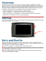
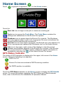
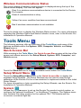
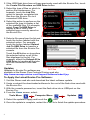
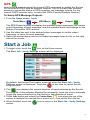
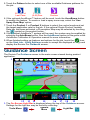
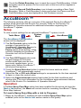
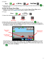
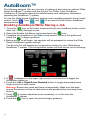
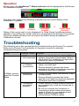
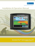
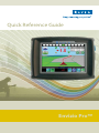
Quick Reference Guide
Envizio Pro™
Overview
The Envizio Pro console is an all-in-one field computer capable of providing
product control for up to two products, supplying GPS information to other in-cab
devices, and providing on-screen guidance during field applications. All of these
features may be controlled at the same time with an easy to use touch screen.
In addition, the Envizio Pro is capable of working with the following:
• Raven AccuBoom™ automatic section control system
• Raven AutoBoom™ automatic boom height control systems
• Raven SmarTrax™ or SmartSteer™ automated steering control systems
• Raven TM-1 Tilt Module for tilt corrected guidance
Startup
To power up the Envizio Pro console, press the power button located on the right
side of the Envizio Pro console.
USB Port
Do’s and Don’ts
Do have the Envizio Pro serial number and firmware revision available when
calling for technical assistance. It is best if the user is in the machine and in front
of the Envizio Pro when calling for support.
Do read the manual in its entirety before using Envizio Pro.
Don’t turn the Envizio Pro off without properly closing any open jobs. If the Envizio
Pro loses power during a job, information within the job files may be lost and the
associated files may become corrupt.
Don’t use sharp objects or harsh chemicals on the Envizio Pro touch screen.
These may damage the display.
1
Home Screen
Touch
anywhere it appears to return to the Home screen.
Touch the:
Start Job icon to begin a new job or resume an existing job.
Tools icon to access the Tools Menu. The Tools Menu contains the
settings and calibrations for the Envizio Pro system.
Shutdown icon to power down the Envizio Pro console. The Shutdown
icon only appears when a job is not in progress. Be sure to shutdown the
console before switching the console off.
End Job icon to close a job in progress. The End job icon only appears if a
job is in progress and replaces the Shutdown icon on the Home screen.
Info icon in the upper, right corner of the display to view the current
software and firmware versions of the Envizio Pro console. If the Envizio
Pro is connected to a CANbus system, additional system information is
available by selecting the
on the About Envizio Pro screen.
GPS Status Indicator
The status of GPS reception is displayed in the upper, left corner of the Home
screen. When the following icon appears:
DGPS is O.K.
Envizio Pro has encountered a DGPS warning condition.
No DGPS position is available.
Touch the GPS Status indicator on the Home screen to display the GPS Health
screen. For more information regarding the GPS Status and Status Indicator
icons, refer to the Envizio Pro Installation & Operation Manual.
2
Wireless Communications Status
The current status of wireless communication is displayed along the top of the
Home screen display. This icon will appear:
Gray if no wireless communications device is connected to the Envizio
Pro console.
Green if communication is okay.
Yellow if an error condition has been encountered.
Red if wireless communication is not available.
Touch the shield icon to display the Wireless Status screen. For more information
regarding the Wireless Status and Status Indicator icons, refer to the Envizio Pro
Installation & Operation Manual.
Tools Menu
The following sections offer an overview of the Tools Menu and some of the
features available within the System, GPS, Computer, Vehicle, and Setup
Wizard menus.
Quick Access Bar
While working in the Tools Menu, the Quick Access Bar remains at the top of the
screen and allows access to the Setup Wizard, System, GPS, Computer, and
Vehicle menus.
Touch the Show All icon to view all available menus within the Tools Menu.
Setup Wizard Menu
Touch the Setup Wizard Menu icon in the Quick Access Bar to display the
available Setup Wizards. The Setup Wizards may be used to step through
calibration of the Envizio Pro for a new machine or implement similar to the Initial
Setup Wizard.
For more information or help completing the Setup Wizards, see the Envizio Pro
Installation & Operation Manual.
System
Access the System menu to set up the Envizio Pro product control system, or
configure the optional AccuBoom™ or AutoBoom™ systems. The System menu
also contains the setup screens for the optional TM-1 Tilt Module and the
on-screen or external light bar.
3
To Retry the CANbus Connection:
If the Envizio Pro does not recognize CAN nodes when the console is first
powered up, the CANbus connection may need to be restarted.
1. From the Home screen, touch
2. When prompted, touch the
to confirm and retry CANbus communication.
If CANbus communication is not re-established, refer to the Envizio Pro
Installation & Operation Manual for troubleshooting information and assistance.
Vehicle
Access the Vehicle menu to set up or modify vehicle profiles for each machine or
implement with which the Envizio Pro will be used. Profiles allow the operator to
set up GPS antenna heights and offsets as well as the swath width and section
setup for each implement and transfer those settings to a home or office PC,
another Envizio Pro console, or reload the Profile at a later date.
To Edit Profiles:
1. From the Home screen, touch:
Tools Menu
Vehicle Menu
Profiles
2. The Profile Manager screen displays with the currently loaded profile
highlighted in the list of profiles stored on the Envizio Pro.
To Create a New Profile:
Touch the
icon and use the
on-screen keyboard to enter the
desired profile name.
To Save a Profile:
Touch the desired profile name in
the list and select the Save Profile
button. The current settings will be
saved to the highlighted profile.
To Load a Profile:
Touch the desired profile name in
the list and select the Load Profile
button.
Computer
The Computer menu sets display and feature settings of the Envizio Pro console.
Access the Computer menu to change the display brightness, language, and
units, as well as activate features or update the Envizio Pro software.
File Maintenance
The File Maintenance feature allows the operator to transfer files to and from the
Envizio Pro console. Files such as saved field boundaries or guidance paths,
coverage maps for completed jobs, and prescription maps may be transfered
using the following procedure.
To Perform File Maintenance:
1. From the Home screen, select:
Tools Menu
Computer Menu
File Maintenance
4
2. If the USB flash drive has not been previously used with the Envizio Pro, touch
the Create File Structure on USB Drive button.
3. Select the type of files on which to
perfom file maintenance. For
example, touch the Job File
option to transfer completed job
files from the Envizio Pro to a
connected USB drive.
4. Select the action to perform on the
selected file type to display a list
of the available files. For example,
select Copy To USB Drive to
display a list of files of the
selected type currently saved on
the Envizio Pro.
File Types
Actions
5. Select a file name from the list and
touch the button labeled with the
selected action. For example,
touch the button labeled Unload
Job To USB Drive to transfer a
selected file from the Envizio Pro
console.
Touch the All button on to perform
the selected action on all of the
files displayed in the list. For
example, select the Unload All to
USB Drive to transfer all the jobs
onto the connected USB flash
drive.
Updates
Perform Action on
All Files
Perform Action on
Selected File
Updates for Envizio Pro software are
available at the Raven Flow Controls Division web site:
http://www.ravenprecision.com/Support/Software/index2.jsp
To Apply the Latest Envizo Pro Software:
1. Visit the Raven web site and download the latest software update.
2. Unzip or extract the downloaded software to the root of the flash drive used with
the Envizio Pro.
3. With the console powered on, insert the flash drive into a USB port on the
Envizio Pro.
4. From the Home screen, select:
Tools Menu
Computer Menu
Updates
5. Select the update to apply and touch the
icon.
6. Once the update is complete, restart the console to finish the update procedure.
5
GPS
Use the GPS menu to adjust the internal GPS receiver or to enable the Envizio
Pro to receive DGPS from an external receiver. The GPS menu also contains
screens to review the status of GPS reception, set message outputs (for the
internal DGPS receiver only), or select the PRN (Pseudo-Random Number).
To Setup GPS Message Outputs:
1. From the Home screen, touch:
Tools Menu
GPS Menu
Output
The GPS Output screen will display the available output messages, the current
output frequency of each message, and the available baud rate settings for the
Envizio Pro built-in GPS receiver.
2. Use the slider bar next to the desired output messages to set the output
frequency, in hertz, for each message.
3. Select the desired baud rate for the output messages from the list on the right
side of the screen.
Start a Job
1. To begin a job, touch the
icon on the Home screen.
The Start Job - Verify Settings screen will be displayed.
By default, the Envizio Pro creates a new job when the Start Job - Verify
Settings screen is displayed. Touch the
at any time to cancel the job
setup process.
2. The
icon displays the current direction of travel detected by the Envizio
Pro console. If this indicator displays the incorrectly, touch the icon to manually
toggle the course direction for the current or last direction of travel.
3. Touch Job button and select the Create New
icon along the top of the
screen to rename the new job file or select a previous job file from the list.
4. When finished, touch the
icon to return to the Start Job - Verify Settings
screen.
6
5. Touch the Pattern button to select one of the available Guidance patterns for
the job:
Enhanced
Straight
Fixed
Pivot
Last Pass
(A-B) Line
Contour
6. If the optional AccuBoom™ feature will be used, touch the AccuBoom button
to enable the feature. To create or load a spray zone map, select the ‘Use
Spray Zone Map’ option.
7. Touch the Product 1 or Product 2 buttons to select the control mode and set
the target application rate for the job. If the optional Single Product Variable
Rate key has been activated, a Prescription Map may be selected by touching
the
symbol on the product button.
8. If the optional AutoBoom™ system will be used, the system may be enabled by
selecting the AutoBoom button. See the AutoBoom section in this guide or the
AutoBoom Calibration & Operation manual for more information.
9. When finished setting up features and options for the job, touch the
icon
on the Start Job - Verify Settings screen to accept the displayed settings and
display the Envizio Pro Guidance screen.
Guidance Screen
The Envizio Pro Guidance screen is the main screen viewed during product
application.
1
2
4
6
8
10
7
3
9
5
12
13 14
15
11
16
17
18
19
1. The On-Screen Light Bar is displayed along the top of the Guidance screen.
Settings for the light bar may be found by selecting:
System
Tools Menu
Light Bar
Menu
7
2. The Tank or Bin Indicator displays the calculated volume of product remaining
in the tank or bin. Touch this indicator to display the Tank or Bin Volume
Configuration screen.
3. The Area Covered displays a tally of the total area covered by active sections
(sections toggled on) within the current job.
4. The GPS Status status indicator is displayed on the Guidance screen. See the
GPS Status Indicator section on page 2 for more information.
5. Touch the Display Mode icon to toggle the day or night modes for the guidance
screen display.
6. This area displays the Speed or Course Over Ground (COG). Touch this area
to toggle the information displayed.
7. The Distance to Swath display shows the distance and direction to the
displayed Guidance path.
8. The SmarTrax™ Status is displayed if an optional SmarTrax™ or QuickTrax™
system is connected to the Envizio Pro. This indicator appears green if the
system is engaged or red if the system is disengaged.
9. The current status of Wireless Communication is displayed on the guidance
screen. See the Wireless Communications Status on page 3 for more
informaiton.
10.The Product Rate Display shows target and actual application rates as well
as indicates the selected product.
Touch the name of a product to toggle the selected product or touch in the rates
area to access the In Job Product Configuration screen. Additional display
options may be activated on the In Job Product Configuration screen.
11.Touch the Rate Bump buttons to increase or decrease the rate of the selected
product. When operating in Automatic control mode, the rate bump buttons will
increase or decrease the target rate. In Manual control mode, these buttons will
adjust the actual application rate.
12.The AccuBoom Override
13.The AutoBoom™ Status Indicator is displayed if an optional AutoBoom™
system is connected to the Envizio Pro. See the AutoBoom™ section for more
information regarding the AutoBoom™ Status Indicator.
14.The Section Status Display shows information for each configured section.
Active sections appear green while sections currently disabled (or toggled off)
appear in white.
15.The Swath Information displays the number of the current swath when using
the Straight Line, Fixed Contour, or Pivot patterns. When using the Enhance
Last Pass pattern, this area displays LAST.
16.The In-Job Nudge Settings
17.Use the Zoom In and Out icons to change the level of detail shown on screen.
18.Touch the Alternate Guidance Pattern button to toggle the pattern used to
provide guidance for the job in progress.
19.Access the Menu to display additional tools and features of the job in progress.
The Menu contains the tools for recording a field boundary and creating or
editing a Guidance Path.
8
Menu
Touch the Menu icon on the Guidance screen to access additional tools and
features of the Envizio Pro. The Menu also offers access to the Envizio Pro Home
screen. The following tools and features may not be accessible at the same time.
Be sure to read the descriptions and ensure appropriate information is displayed
on-screen to allow access to the following features and tools.
Guidance Views
The following views are available for the Envizio Pro Guidance screen:
The Down Field view is displayed each time the guidance screen is
displayed. This view represents the view from the vehicle cab.
Switch to the Bird’s Eye view to display a view looking down from above
the vehicle’s current location.
Use the Field Review Mode to display large areas of an application map
and areas of the field in which the vehicle is not currently located. If an
optional VRA key is activated, access the Field Review Mode to display
Prescription Map information.
Guidance Path (A-B) Tools
The following tools and features may be found in the Menu when the Straight Line,
Fixed Contour, or Pivot guidance patterns are active.
To Load an A-B Line:
Touch the Load A-B Line icon to load a previously saved line into the
current job. This icon will not appear if an A-B Line has already been set.
Reset the line to access the Load A-B Line tool.
To Create A-B Line:
Note: The Set A and Set B icons will be displayed on the Guidance screen when
the Straight Line Guidance Pattern is active.
Touching the Set A icon will place the first, or A, point of the path at the
vehicle’s current location. Regardless of where the vehicle moves from this
point, the Envizio Pro will use the selected pattern to connect this point with
the next set point. After the Set A icon is selected, the Set B icon will
appear.
Touch the Set B icon to place the second, or B, point of the guidance path.
Once the B point has been set, the Envizio Pro will use the selected Pattern
to create the Guidance Path displayed on the Guidance screen.
Set B by Heading Feature:
Use the Set B by Heading feature to create a guidance path along a
heading. Touch this icon and use the displayed keypad to enter a heading
between 0° and 359° (with 0° being due North).
Note: The Set B by Heading feature is only available with the Straight Line
Guidance Pattern.
To Configure a Displayed A-B Line:
Select the A-B Tools icon to access additional tools for use with the current
A-B Line.
9
Select the Reset A-B Line icon to clear the displayed path. If the displayed
path will need to be recalled in the future, be sure to save the current path
before selecting reset.
Touch the Save A-B Line icon to save the displayed path. Once saved, an
A-B Line can be recalled at any time or loaded into other jobs. In addition,
saved paths can be transferred from the Envizio Pro via the File
Maintenance feature. Refer to the Envizio Pro Installation & Operation
Manual for details on the File Maintenance feature and transferring saved paths.
Use the Re-calibrate A-B Line tool to re-calibrate the displayed path to the
machine’s current position. Due to DGPS drift over time, this feature allows
the operator to re-calibrate the A-B Line to a known position in a field.
In-Job Nudge Settings:
The Nudge Feature allows the operator to fine tune the displayed path for actual
field conditions.
Touch the Nudge Settings icon to display options for the in-job nudge
controls and enable the on-screen nudge controls.
With the on-screen nudge controls enabled:
Touch the Nudge Right icon to move the guidance path to the right in the
increments set on the Nudge Settings screen.
Touch the Nudge Left icon to move the guidance path to the left in the
increments set on the Nudge Settings screen.
Recording a Field Boundary
To Record a Field Boundary:
1. Begin a job file by following the procedure outlined in the Starting a Job section.
2. With the vehicle stopped and positioned at the start of the field boundary, touch:
Field
Record Field
Menu
Boundary Tools
Boundary
3. Begin driving the boundary of the field. The Envizio Pro will create a path
displayed in yellow.
4. At anytime you may press Pause
to temporarily stop recording the field
boundary. This feature is useful when refilling a product or when the vehicle’s
path will not reflect the actual field boundary. Touch Resume
to continue
recording the current boundary.
5. To close the field boundary, touch the End
icon on the Guidance screen.
The Envizio Pro will connect the starting point of the boundary to the vehicle’s
current location with a straight line when closing a boundary.
Other Field Boundary Tools
The following icons will be used while creating a Field Boundary.
Touch the Boundary Tools icon to display boundary tools available for the
current job.
A previously recorded boundary can be loaded into the current job file by
selecting the Load Field Boundary icon in the Menu. A list of job files
stored on the Envizio Pro is displayed. Select the job name to load the
boundary recorded that Field Boundary into the current job.
10
Touch the Delete Boundary icon to reset the current Field Boundary. A field
boundary must be present in the current job or this icon will not appear in
the Menu.
Touch the Record Field Boundary icon to begin recording a New Field
Boundary. While a Field Boundary is being recorded, the Pause and End
Field Boundary icons are displayed on the Guidance screen.
AccuBoom™
The following sections offer an overview of the optional Raven AccuBoom™
system when used with the Envizio Pro console. Refer to the Envizio Pro
Installation & Operation manual for additonal information regarding the
AccuBoom™ system.
Setup
To view current settings for an optional AccuBoom™ system, touch:
System
AccuBoom
Tools Menu
Menu
The AccuBoom Configuration
screen will be displayed.
1. The On Override option is the the
number of seconds for the
1
2
AccuBoom™ Override. Be sure to
check the Enable Override
Popup option at the bottom of the
3
screen to display the AccuBoom™
4
Override icon on the Guidance
5
screen.
2. The Turn Off Percent value sets
the percentage of the boom
section width that must be in a
previously applied area, or nospray zone, before AccuBoom™
will control that section.
3. Touch the Boom Selection button to select the boom sections which
AccuBoom™ will automatically control.
4. Adjust the On or Off Look Ahead settings to compensate for the time required
to open or close the control valve.
5. Select the Aggressiveness setting best suited for the field conditions and
driving style. For more information on the AccuBoom aggressiveness feature,
refer to the Envizio Pro Installation & Operation Manual.
Operation
If the Use Spray Zone Map option has been enabled for the active job (see the
Start a Job section), the Menu will contain tools for recording AccuBoom™ Spray
Zone Map features.
To Load a Spray Zone Map with a Job in Progress:
1. Begin an AccuBoom™ enabled job with the Use Spray Zone Map option
enabled (refer to the Start a Job section earlier in this guide).
11
2. Touch:
Menu
Spray
Zone Tools
Load Spray
Zone Map
3. Select the name of the desired Spray Zone Map from the list and touch
load the map.
to
To Edit the Spray Zone Map:
1. Begin an AccuBoom™ enabled job with the Use Spray Zone Map option
enabled (refer to the Start a Job section earlier in this guide).
2. Touch:
Spray
Menu
Zone Tools
3. Select the following icons to begin recording a:
No-Spray
Spray
Field
Zone
Zone
Boundary
4. Select the reference point of the vehicle and then touch the
icon.
5. The Guidance screen will re-appear and Envizio Pro will begin recording the
boundary or feature. On the Guidance screen, a Pause and End icon appear for
the feature currently being recorded.
Recorded
Path
Pause and
End Icons
AccuBoom™
Override
The Guidance screen will also display a reminder above the Menu icon when
the Envizio Pro is in Spray Zone Edit mode. The Menu contains the tools for
editing Spray Zones when this reminder appears. To exit the edit mode, touch
the
icon within the Menu.
12
AutoBoom™
The following sections offer an overview of setting up and using an optional Glide
Series AutoBoom™ system with the Envizio Pro. Refer to the AutoBoom
Calibration & Operation manual for detailed setup and calibration information
regarding the AutoBoom™ system.
To view the Glide Series AutoBoom settings and to enable automatic boom height
control, touch
, then
and
to access the Glide Series AutoBoom
setup screens.
Enabling AutoBoom While Staring a Job
1. Touch the
icon on the home screen and touch the AutoBoom button on the
Start Job - Verify Settings screen.
2. Select the Enable AutoBoom option and touch the
icon.
3. Complete the procedure in the Start a Job section earlier in this guide and
select the
to begin guidance.
4. Before guidance will begin, the operator will be prompted to review the Glide
Series AutoBoom system settings.
The Envizio Pro will display the configuration screen for your Glide Series
AutoBoom™ system. This configuration screen will look similar to the following:
5. If
is displayed in the upper right corner, touch the icon to toggle the
AutoBoom system on.
6. Touch the Left or Right Boom Disabled button to toggle automated boom
height control for each boom.
Warning: Booms may raise and lower unexpectedly. Make sure the area
around the booms is clear of obstructions and people before touching these
buttons.
7. Touch
if system adjustments are necessary, or to fine tune the
AutoBoom™ system.
8. Touch the
icon to open the job and begin guidance.
13
Operation
During a job, the AutoBoom™ Status Indicator will be displayed on the Envizio
Pro Guidance screen.
This area may display the following indicators for the current status of the
AutoBoom™ system:
or
Left/Right
Center Rack
Enabled
Enabled
Status of the center rack is only displayed if a Glide Series AutoBoom system
capable of controlling the center section is connected to the Envizio Pro console.
Touch the displayed status icon to access the Glide Series AutoBoom™
Calibration screen.
Disabled
Off
Both
Enabled
Troubleshooting
The following are a few general tips for troubleshooting the Envizio Pro system.
Refer to the Envizio Pro Installation & Operation manual for detailed
troubleshooting information.
Issue
Possible Cause
Solution
• CANbus ends • Make sure that both ends of the CANbus
not terminated
system are properly terminated. Refer to
the Envizio Pro Installation & Operation
manual for more information.
• Corroded pins • Check CANbus cable connectors for any
in CANbus
highly corroded pins.
connections
• Ensure dielectric grease has been
applied to all cable connections exposed
to weather and field conditions.
CANbus cannot • Moisture in
connection
read the Product
Node
• Check CANbus cable connectors for any
corroded pins.
• Ensure dielectric grease has been
applied to all cable connections exposed
to weather and field conditions.
• Connectors
not seated
properly
• Check that all CANbus cable connectors
are inserted fully (until the locking tab is
engaged).
• Be sure to remove any moisture in
connections which were not properly
seated. Check for corroded pins and
apply dielectric grease when
reconnecting CANbus cables.
14
Envizio Pro™
Quick Reference Guide
(P/N 016-0171-149 Rev C 12/09)
Raven Industries
Applied Technology Division
P.O. Box 5107
Sioux Falls, SD 57117-5107
Toll Free (U.S. and Canada): (800)-243-5435
or Outside the U.S. :1 605-575-0722
Fax: 605-331-0426
www.ravenprecision.com
[email protected]
Notice: This document and the information provided are the property of Raven Industries, Inc. and
may only be used as authorized by Raven Industries, Inc. All rights reserved under copyright laws.