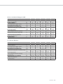
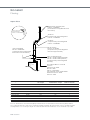
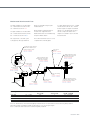
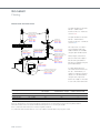
1
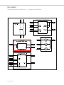
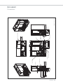
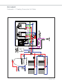
EW
N
Ecoskid
Prefabricated Heating System
56kW – 230kW
Working towards
a cleaner future
heating specialists
page
3
Overview
Explanatory Image
4&5
Ecoskid Boiler Options
6
LZC Technology – CHP Option
7&8
Water Heater Integration
9
Components
Controls
10
11 & 12
Panel Wiring
13
Panel Mounted Connections
14
Dimensions
15
Schematic – Two Heating Zones
16
Schematic – Two Heating Zones
plus Hot Water
17
Data Tables
18 & 19
Flueing
20 – 22
Testing, Delivery & Installation
23
Warranty, Service and
Service Contracts
23
2 ECOSKID
Ecoskid
Prefabricated Heating System
56kW – 230kW
Overview
The Ecoskid has been designed to provide the market place with an easy to install,
fully pre-fabricated heating system with the ability to incorporate LZC products such
as the Baxi Ecogen micro-CHP. The Ecoskid can also be accompanied by a direct
fired condensing water heater, such as the Andrews NEOflo which enables
dedicated hot water provision. The Ecoskid offers reduced installation time on site,
providing substantial cost savings and reduced system down times.
For system selection the Ecoskid offers:
Unlike other skid assemblies on the
market, the Ecoskid has the optional
benefit of an onboard micro-CHP
appliance, which is pre-installed and
configured on the skid to enable
almost any site to have the benefits of
micro power generation, without the
trouble of integrating these appliances
in to control systems or electrical
supplies.
• A choice of either a two boiler skid
assembly or a single boiler installed
along side a Baxi Ecogen micro-CHP
unit
• The boilers can be chosen from
either the Paramount two or the Sirius
WH boiler (see page 6)
• Small footprint
• The Ecoskid is supplied on a fully
welded, powder coated frame which
can be manoeuvred easily onsite by
means of forklift truck, skates or
manually using rollers.
Onsite installation aid for the
Ecoskid includes:
• Delivery to site fully assembled
• Only requires connection of the gas,
flow, return and mains water pipe work
to the pre-installed isolation valves
• Connection of a single phase 230V
supply to the control panel
• The pressure relief pipework has
been combined for ease of on site
continuation to a suitable discharge
point or drain
Further Options
• The Baxi Ecogen micro-CHP
incorporates a Stirling engine unit
which, when fired, modulates its
output between 4kW and 6kW
thermal, whilst generating up to
1.1kW of electricity.
• The Ecoskid can be further
enhanced by the integration of the
Baxi-SenerTec UK Dachs mini-CHP
unit or twin coil cylinders for
incorporating solar hot water
production
• Flexible controls for connection
to a BMS or stand alone control
• Optional extra control packs to
enhance the standard control panel’s
functionality with out the need to
modify the wiring or skid assembly
• The skid assembly has been
designed to fit through a standard
doorway, making it suitable for both
existing and new plant rooms alike
ECOSKID 3
Ecoskid
Pre wired and installed,
flexible control panel
with a range of optional
extras to expand its
functions to meet the
site requirements
Integral cable
management tray
Pressurisation unit
for system filling and topping
up – low and high pressure
alarms wired to main
control panel
Commoned condensate
and pressure relief
pipework to aid installation
Full bore isolation valves for
easy onsite connection
Pressure differential bypass
to ensure minimum flow
through the boilers
4 ECOSKID
Choice of two main boilers:
Paramount two – cast
aluminium/silicon alloy heat
exchanger
Sirius WH – stainless steel heat
exchanger
The Ecoskid has the option of
a Baxi Ecogen/Dachs CHP in
place of a second boiler to offer
substantial carbon and running
cost reduction
Pressure and temperature
gauges on common flow
and return pipework header
Purge and vent points
are pre-installed and
plugged off
Gas isolation valve
supplied to feed additional
appliance (Andrews Water
Heaters NEOflo)
Differential pressure flow
switch for flow proving
Class 'A' rated energy
efficient twin head pumps
with automatic changeover
and pump exercise functions
ECOSKID 5
Ecoskid
Ecoskid Boiler Options
The Ecoskid has been designed to take
advantage of high efficiency modern
condensing boilers. We offer a choice of two
boilers for the Ecoskid which allows the right
boiler to match the application.
Paramount two Boilers
• Cast aluminium/silicon alloy heat
exchanger
• Low NOx emmisions, <20mg/kWh
• Efficiencies of up to 96% gross, seasonal
• Quick release isolation valves
• Suitable for both LPG and Natural gas
Sirius WH Boilers
•
•
•
•
•
Stainless steel heat exchanger
Low NOx emmisions, <39mg/kWh
Efficiencies of up to 94% gross, seasonal
Quick release isolation valves
Suitable for both LPG and Natural gas
6 ECOSKID
LZC Technology
Baxi Ecogen™
What is micro-CHP?
Electricity from the national grid is generated by large,
remote power stations which every year waste enough
energy to heat most of our buildings. This huge waste of
energy results in very inefficient and very expensive grid
supplied electricity.
Micro-Combined Heat and Power (CHP) is the
simultaneous generation of heat and electricity, close to the
point of use. By locating micro-CHP equipment in or close
to a building, the electricity generated and the heat
produced can be used in the building with little energy
wastage.
Carbon saving technology
Micro-CHP is a key microgeneration technology which can
deliver carbon savings of 20%-30%. It is a mature, reliable
technology which delivers very attractive financial benefits
and can play a big part in gaining compliance with planning
and Building Regulations.
E
Micro-CHP Functions
The Baxi Ecogen micro-CHP incorporates a Stirling engine
unit which, when fired, modulates its output between 4kW
and 6kW thermal, whilst generating up to 1.1kW of
electricity. The electricity which is generated from the Baxi
Ecogen is offset against the customer’s electricity bills
providing substantial running cost savings.
The onboard control system is configured to use the
Baxi Ecogen engine as the lead appliance to maximise the
benefits of using small scale micro generation and maximise
the reduction in carbon emissions. If the load is greater than
6kW, the main boiler is then brought in to operation to
satisfy this demand. At peak times the auxiliary burner on
the Baxi Ecogen will then be brought in to operation to
provide a final heat source.
Energy efficiency comparison
81% overall
efficiency
CENTRAL GENERATION ENERGY EFFICIENCY
LOCAL GENERATION ENERGY EFFICIENCY
*Based on 91% winter efficiency (SEDBUK)
and 75% summer efficiency
35%
efficiency
88%
efficiency*
electricity
heat
85% overall
efficiency
gas
Band A
boiler
electricity
gas
heat
BAXI
ECOGEN
ECOSKID 7
LZC Technology
Baxi Ecogen micro-CHP Option
The Ecoskid can be provided with an integral Baxi Ecogen
micro-CHP unit. This reduces the carbon footprint of the
system by displacing the CO2 emissions associated with
gas fired power generation of electricity. The Baxi Ecogen
reduces the operational cost of the site by reducing the
electrical requirement purchased from the electrical supplier.
The control system automatically utilises the Baxi Ecogen as
the lead boiler to maximise the carbon reduction associated
with micro-CHP technology.
Baxi Ecogen Performance Details
• 6kW Thermal output @ 1.1kW Electrical output
• 18kW additional thermal output from additional burner
• 90% overall operating efficiency
• Low noise <45dB(A) @ 1M
• Maintenance free sealed sterling engine
Baxi Ecogen CO2 Emission Reduction
• 0.359kg/Hr CO2 reduction at 6kW base load
• Annual CO2 reduction up to 3,136 Kg
Electrical Grid Reduction
• 8,760kWh per annum at 6kW thermal base load
• Annual saving at £0.12p kWhr = £1,051
Conventional set-up
4.44 kWh @ 0.185 kg* CO2 = 0.817 kg CO2
BAXI Boiler 90% Efficiency
GAS
HEAT
4kW
1kWh @ 0.544 kg CO2
1kW
MAINS ELECTRICITY
Carbon emissions
per hour
TOTAL
1.365kg CO2
Set-up with Baxi Ecogen
BAXI micro-CHP 90% Efficiency
HEAT
5.56 kWh @ 0.184 kg CO2 = 1.023 kg CO2
4kW
GAS
TOTAL
1.023kg CO2
MAINS ELECTRICITY
*CO2 emission inex figures sourced from Carbon Trust (Feb 2011)
8 ECOSKID
Carbon emissions
per hour
1kW
Ecoskid
Water Heater Integration
The Ecoskid has been designed to
work alongside our highly efficient
appliances from the Baxi Commercial
Division range. The Ecoskid has the
facility to feed an additional appliance
like the NEOflo, with both electric and
gas services being fed directly from
the Ecoskid.
The NEOflo range of condensing
direct-fired storage water heaters are
the latest models to emerge from
market leading Andrews Water
Heaters. Employing a single upward
firing pre-mix burner technology,
NEOflo offers high fuel efficiencies
and ultra low NOx of around 25ppm,
satisfying the increasing demands
of stringent building regulations.
NEOflo water heaters utilise highly
durable stainless steel internal storage
cylinders with available capacities of
200 litres, 300 litres and 400 litres and
an impressive recovery rate of 430
litres per hour.
The low internal pressure loss across
the stainless steel heat exchanger and
internal water way enables NEOflo
water heaters to operate in those
areas of the country where low water
pressure is prominent.
Available as a room sealed or
conventional flued appliance, NEOflo
offers flexibility with regard to the
location of the water heater and
discharge of the products of
combustion.
A digital Human Machine Interface
is present on the appliance displaying
key parameters with the ability to
connect to an on-site Building
Management System (BMS) for control
and supervision.
ECOSKID 9
Ecoskid
Components
System Pumps
• Class ‘A’ rated intelligent pumps
• Twin head assembly arranged in a
duty/standby configuration
• Differential pressure switch for flow
proving, complete with automatic
changeover
• Choice of operation modes selected
using the inbuilt pump controls
Arrow Fill Unit
• Inbuilt and configured Arrow
pressurisation unit
• Integral high and low pressure
switches pre-wired to the main system
controls
• Low water pressure alarm
• Onboard LCD for setting system and
alarm pressures
Pressure and Temperature Gauges
• 80mm combined temperature and
pressure gauges
• Gauges fitted with isolation valves
for easy service/maintenance
Differential Pressure Bypass
• Pressure set bypass valve fitted
across the flow and return
• Guarantees the minimum flow rate
through boilers when external controls
shut down
10 ECOSKID
Ecoskid
Controls
The Ecoskid has a built in and pre-configured control panel that offers a great deal of flexibility and integration. The
control panel is supplied pre-wired with all looms secured to the onboard cable management system, meaning the
installer only needs to connect the single phase 230v supply to the control panel, saving both time and material
costs on having to install and integrate control systems.
The standard panel comes
ready for BMS integration
and has connections.
Available for monitoring the
status of the main system
components and for
controlling the system using
a 0 – 10v signal (Relating to
0 – 100% of total system
output). See page 14 for more details on the available
connections for monitoring and BMS integration.
The controls for the Ecoskid
require no more than single
phase 230v 50hz supply to
be connected directly in to
the control panel. Each
piece of equipment has a
MCB to offer protection and
an individual isolator to enable each piece of equipment to
be isolated individually with out the need to shut down the
rest of the system for ease of maintenance.
The front panel has a
number of blank labels that
can be changed by
removing the four screws
and fitting an alternative
label. This facility has been
provided to allow the control
panel to be expanded with
the use of optional extra
packs.
Where these optional extra
packs are used, you will
find behind the label on the
rear of the door, all the
connections to complete
the installation of these
packs. Optional packs are
provided for:
• Weather compensated controller
• Constant flow temperature controller
• Time control (for use with a constant temperature
or weather compensated controls)
• Frost protection (3 Stage)
• Additional isolator for water heater integration
When either the constant flow or weather compensator
controls are used, they provide the 0 – 10v signal and can
be used as a stand alone control option either with or
without a time switch.
If a BMS is still used to enable and monitor the system
the BMS 0 – 10v input connections can now be used
to monitor the output of the system (0 – 100% of total
system output).
The 0 – 10V signal from
either of the methods
above, is fed in to a robust
and reliable Mitsubishi PLC
which controls the system
by sequencing and
modulating the boilers to
closely match the system demand whilst ensuring the
system operates at its most efficient by utilising the various
heat sources in the correct sequence.
ECOSKID 11
Ecoskid
Controls
Sequence of Operation
The PLC will always bring on the Baxi
Ecogen engine (If a Baxi Ecogen
version is requested), as using the
engine for as long as possible will
maximise both the carbon savings and
electrical output from the micro-CHP.
If this does not satisfy the load, the
condensing boiler will be brought in to
operation and modulated to match the
heat demand.
At peak heat demand, the auxiliary
burner on the Baxi Ecogen will fire to
provide a final source of heat.
Pump/Flow Monitoring
The PLC will monitor the pump and
flow conditions of the system and
ensure that both pumps are operated
equally in respect to hours run. The
PLC will monitor for flow fail and bring
on the standby pump should a flow fail
condition be observed. Each pump is
operated once a week to ensure the
pump heads do not seize during
periods of non-use.
Flow proving is provided by a
differential pressure switch.
Frost protection
Frost protection is provided via an
optional extra pack that is supplied
with an outside thermostat and two
immersion stats that fit in to the
pockets provided on the return pipe.
Once fitted, the frost protection will be
activated once a user set temperature
is observed by the outside thermostat.
This will operate the pumps until the
outside temperature increases and this
thermostat is satisfied.
Once the frost protection is activated
and the pumps are running, the
system then monitors the return pipe
temperature. If the temperature is
below a user set value, the system will
start the Baxi Ecogen engine to
provide an input of up to 6kW (On twin
boiler versions the system operates
12 ECOSKID
Boiler No1 and modulates it as
required). This engine will operate as
required until either the temperature
rises above the thermostats trigger
point or the temperature drops past
the user set value for the second frost
immersion thermostat. If this second
immersion thermostat is triggered, the
system will then allow the second
boiler to fire to provide full load in to
the system to ensure the building is
protected at all times, whilst operating
as efficiently as possible.
Hot Water Functions
The Ecoskid caters for hot water
integration in a number of ways, either
by using a dedicated water heater fed
from the Ecoskid or by means of a
temperature boost function. If the
system is fitted with the weather
compensated controller, the system
may not be operating at a high enough
temperature during mild periods to
provide hot water. This can be
overcome by giving the system an
override signal (via vfc) which will
enable the Ecoskid to operate at
maximum temperature until the hot
water is satisfied and the override
signal removed. An end switch on a
three way diverter valve can be used
for this purpose. Once the signal has
been removed, the system will revert
back to the temperature requested
from the controller. This enables the
system to operate in condensing mode
for as long as possible while still
supplying your hot water requirements.
See page 14 for more information on
the electrical connection of optional
extra packs.
Ecoskid
Panel Wiring
A
Available Inputs
Alarm Telemetry Connections
REMOTE SHUTDOWN
(LINK IF NOT REQ)
(BREAK TO SHUT DOWN)
30
31
SAFETY INTERLOCK 1
(LINK IF NOT REQ)
(BREAK TO SHUT DOWN)
32
33
SAFETY INTERLOCK 2
(LINK IF NOT REQ)
(BREAK TO SHUT DOWN)
34
35
SAFETY INTERLOCK 3
(LINK IF NOT REQUIRED)
(BREAK TO SHUT DOWN)
36
37
SAFETY INTERLOCK 4
(LINK IF NOT REQ)
(BREAK TO SHUT DOWN)
38
39
REMOTE ENABLE
(LINK IF NOT REQ)
(BREAK TO SHUT DOWN)
40
41
HOT WATER OVERRIDE
(MAKE TO OVERRIDE)
(OPTIONAL - NOT REQ)
42
43
100
101
REMOTE ENABLE
CLOSED CIRCUIT = ENABLED
102
103
REMOTE SHUTDOWN / SAFETY SHUT DOWN
CLOSED CIRCUIT = SYSTEM INHIBITED
104
105
LOW PRESSURE FAULT
CLOSED CIRCUIT = LOW PRESSURE
106
107
HIGH PRESSURE FAULT
CLOSED CIRCUIT = HIGH PRESSURE
108
109
PLC FAULT
CLOSED CIRCUIT = PLC AT FAULT
110
111
BOILERS ENABLED
CLOSED CIRCUIT = BOILERS ENABLED
112
113
BOILER No 1 / ECOGEN 1ST STAGE RUN
CLOSED CIRCUIT = RUNNING
114
115
ECOGEN 2ND STAGE RUN
CLOSED CIRCUIT = RUNNING
116
117
BOILER No 2 RUN
CLOSED CIRCUIT = RUNNING
118
119
BOILER No 1/ ECOGEN 1ST STAGE FAULT
CLOSED CIRCUIT = AT FAULT
120
121
ECOGEN 2ND STAGE FAULT
CLOSED CIRCUIT = AT FAULT
122
123
BOILER No 2 FAULT
CLOSED CIRCUIT = AT FAULT
124
125
LEAD HEATING PUMP FLOW FAIL
CLOSED CIRCUIT = FLOW FAIL
126
127
STANDBY HEATING PUMP FLOW FAIL
CLOSED CIRCUIT = FLOW FAIL
128
129
HEATING PUMP 1 ENABLED
CLOSED CIRCUIT = PUMP ENABLED
130
131
HEATING PUMP 2 ENABLED
CLOSED CIRCUIT = PUMP ENABLED
SCR
132
133
HOT WATER TEMPERATURE OVERRIDE
CLOSED CIRCUIT = IN OVERRIDE MODE
51
52
134
135
TEMPERATURE CONTROLLER FAULT
CLOSED CIRCUIT = CONTROLLER FAULT
SCR
136
137
BOILER AUTO / MANUAL SWITCH
CLOSED CIRCUIT = BOILERS IN MANUAL
138
139
PUMP AUTO / MANUAL SWITCH
CLOSED CIRCUIT = PUMPS IN MANUAL
Sensor Connections
OUTSIDE SENSOR - PT1000
(WEATHER COMPENSATOR OPTION ONLY)
(OPTIONAL - NOT REQ)
44
45
SCR
ROOM SENSOR - PT1000
(WEATHER COMPENSATOR OPTION ONLY)
(OPTIONAL - NOT REQ)
46
47
WATER TEMP SENSOR - PT1000
(WEATHER COMPENSATOR OPTION ONLY)
(OPTIONAL - NOT REQ)
WATER TEMP SENSOR - PT100
(CONSTANT FLOW CONTROL OPTION ONLY)
(OPTIONAL - NOT REQ)
48
49
50
BMS CONTROL INPUT 0 - 10V
IF EITHER THE CONSTANT FLOW
TEMPERATURE OR WEATHER
COMPENSATED CONTROL IS USED
THEN THESE CONNECTIONS BECOME A
0 - 10V OUTPUT FOR MONITORING THE
SYSTEM OUTPUT
Optional Pack Connections
FROST STAT - STAGE 1 (OUTSIDE STAT)
(MAKE ON FROST DETECTION)
(OPTIONAL - NOT REQ)
58
59
FROST STAT - STAGE 2 (RETURN STAT)
(MAKE ON FROST DETECTION)
(OPTIONAL - NOT REQ)
60
61
FROST STAT - STAGE 3 (RETURN STAT)
(MAKE ON FROST DETECTION)
(OPTIONAL - NOT REQ)
62
63
5
ECOSKID 13
Ecoskid
Panel Mounted Connections – Optional Extras Pack
1st stage
2nd stage
3rd stage
14 ECOSKID
619
85
Return
Gas
Flow
Drain87
PRV Ø28mm Copper
Condensate Drain - Ø40 Plastic
Flow/Return Ø50mm BSP
MCWS - Ø22 Copper
309
239
110
433
302
171
Gas 40mm BSP
Control Panel
Flow Drain/Fill point 15mm BSP
Return Drain/Fill point 15mm BSP
Lockshield 15mm BSP
Earth Bar 6 way
Sirius Boiler
WH50-70
Return
PRV
Gas
Arrow Autofill Device
182
600
Flow
130
450
Return
1066
938
922
Ecogen
Flow
Gas
752
438
205
172
185
Gas Test point 20mm BSP
Gas 40mm BSP
(plugged)
Lockshield 15mm BSP
Exp. Vessel connection
(plugged)
PRV
204
Manual Air Vent Flow & Return
309
996
714
171
302
433
Return drain/fill
Gas
Flow drain/fill
Gas 40mm BSP
1802
All dimensions are in mm
182
2100
Ecoskid
Dimensions
ECOSKID 15
Ecoskid
Schematic – 2 Heating Zones
16 ECOSKID
Ecoskid
CWM
DHW
Schematic – 2 Heating Zones plus Hot Water
ECOSKID 17
Ecoskid Data Tables
Paramount and Baxi Ecogen CHP
MODEL NUMBER
Boiler 1 Size (Max Output)
Mini-CHP Size (Max Output)
Total Output (Min/Max)
Gas Consumption @ Max Output – Nat Gas
Gas Consumption @ Max Output – LPG
Nominal Inlet Gas Pressure (Nat Gas/LPG)
Available External Pump (Head – Flow Rate @ 20∆°C)
Electrical Supply Voltage
Power Consumption @ Max Flow (Start/Run)
External Flue Size (Boilers/Baxi Ecogen CHP)
Unit
kW
kW
kW
M³/Hr
M³/Hr
mbar
kPa –
Ltr/sec
V / Hz
A
mm
Hydraulic Operating Pressure (Min/Max)
Maximum Flow Temperature
Skid Weight (Empty)
Bar
°C
kg
ECO-P56E
30
26
56
5.66
2.18
ECO-P66E
40
26
66
6.46
2.49
ECO-P86E ECO-P106E ECO-P121E ECO-P141E
60
80
95
115
26
26
26
26
86
106
121
141
8.46
10.46
12.56
14.66
3.26
4.03
4.83
5.64
19 –23 / 35 –39
101.15 kPa 101.15 kPa 101.15 kPa 98.59 kPa 97.41 kPa 99.09 kPa
@ 0.67
@ 0.79
@1.03
@1.27
@1.45
@1.69
230/50
230/50
230/50
230/50
230/50
230/50
7.94 / -0.9 7.96 / -0.88 8.00 / -0.84 8.15 / -0.69 8.44 / -0.4 8.85 / -0.01
80/125
80/125
110/160
110/160
110/160
110/160
60/100
60/100
60/100
60/100
60/100
60/100
1bar –3bar 1bar –3bar 1bar –3bar 1bar –3bar 1bar –3bar 1bar –3bar
80
80
80
80
80
80
486
486
494
505
517
517
ECO-P60
2 x 30kW
60
6.4
2.46
ECO-P80
2 x 40kW
80
8
3.08
2 x Paramount Boilers
MODEL NUMBER
Number of Boilers
Total Output (Min/Max)
Gas Consumption @ Max Output – Nat Gas
Gas Consumption @ Max Output – LPG
Nominal Inlet Gas Pressure (Nat Gas/LPG)
Available External Pump (Head – Flow Rate @ 20∆°C)
Electrical Supply Voltage
Power Consumption @ Max Flow (Start/Run)
External Flue Size
Hydraulic Operating Pressure (Min/Max)
Maximum Flow Temperature
Skid Weight (Empty)
18 ECOSKID
Unit
kW
M³/Hr
M³/Hr
mbar
kPa –
Ltr/sec
V
A
mm
Bar
°C
kg
108.72 kPa 103.81 kPa
@ 0.72
@ 0.96
230/50
230/50
3.68 / 3.44 3.72 / 3.46
80 / 125
80 / 125
1bar –3bar 1bar –3bar
85
85
424
424
ECO-P120
2 x 60kW
120
12
4.62
19 - / 35 – 39
109.94 kPa
@ 1.44
230/50
3.80 / 3.49
110 / 160
1bar –4bar
85
440
ECO-P160
2 x 80kW
160
16
6.15
ECO-P190 ECO-P230
2 x 95kW 2 x 115kW
190
230
20.2
24.4
7.77
9.38
109.14 kPa 104.31 kPa
@ 1.91
@ 2.27
230/50
230/50
4.10 / 3.65 4.68 / 3.94
110 / 160 110 / 160
1bar –4bar 1bar –4bar
85
85
462
486
98.16 kPa
@ 2.75
230/50
5.5 / 4.35
110 / 160
1bar –4bar
85
486
Sirius and Baxi Ecogen CHP
MODEL NUMBER
Boiler 1 Size (Max Output)
Mini-CHP Size (Max Output)
Total Output (Min/Max)
Gas Consumption @ Max Output – Nat Gas
Gas Consumption @ Max Output – LPG
Nominal Inlet Gas Pressure (Nat Gas/LPG)
Available External Pump (Head – Flow Rate @ 20∆°C)
Electrical Supply Voltage
Power Consumption @ Max Flow (Start/Run)
External Flue Size (Boilers/Baxi Ecogen CHP)
Unit
kW
kW
kW
M³/Hr
M³/Hr
mbar
kPa –
Ltr/sec
V / Hz
A
mm
Hydraulic Operating Pressure (Min/Max)
Maximum Flow Temperature
Skid Weight (Empty)
Bar
°C
kg
ECO-S76E
50
26
76
7.37
2.84
ECO-S86E
60
26
86
8.46
3.26
101.15 kPa
@ 0.91
230/50
8.35 / -0.49
80/125
60/100
1bar –3bar
80
496
ECO-S96E
70
26
96
9.54
3.67
19 – 23 / 35 – 39
99.34 kPa
98.43 kPa
@ 1.03
@ 1.14
230/50
230/50
8.39 / -0.45
8.78 / -0.06
80/125
80/125
60/100
60/100
1bar –3bar
1bar –3bar
80
80
501
505
ECO-S116E
90
26
116
11.68
4.50
ECO-S136E
110
26
136
13.56
5.22
98.21 kPa
@ 1.39
230/50
9.02 / 0.18
110/160
60/100
1bar –3bar
80
515
97.32kPa
@ 1.63
230/50
9.44 / 0.60
110/160
60/100
1bar –3bar
80
519
ECO-S100
2 X 50kW
60
8.82
3.78
ECO-S120
2 x 60kW
80
12
4.62
ECO-S140
ECO-S180
2 x 70kW
2 x 90kW
120
160
15.6
18.44
6.00
7.09
19 –23 / 35 –39
93.78 kPa
92.22 kPa
@ 1.67
@ 2.15
230/50
230/50
5.36 / 4.28
5.84 / 4.52
80 / 125
110 / 160
1bar–4bar
1bar–4bar
85
85
462
482
ECOP-S220
2 x 110kW
190
22.2
8.54
104.76 kPa
@ 1.20
230/50
4.5 / 3.85
80 / 125
1bar –3bar
85
446
97.34 kPa
@ 1.44
230/50
4.58 / 3.89
80 / 125
1bar –3bar
85
454
2 x Sirius Boilers
MODEL NUMBER
Number of Boilers
Total Output (Min/Max)
Gas Consumption @ Max Output – Nat Gas
Gas Consumption @ Max Output – LPG
Nominal Inlet Gas Pressure (Nat Gas/LPG)
Available External Pump (Head – Flow Rate @ 20∆°C)
Electrical Supply Voltage
Power Consumption @ Max Flow (Start/Run)
External Flue Size
Hydraulic Operating Pressure (Min/Max)
Maximum Flow Temperature
Skid Weight (Empty)
Unit
kW
M³/Hr
M³/Hr
mbar
kPa –
Ltr/sec
V
A
mm
Bar
°C
kg
91.06 kPa
@ 2.63
230/50
6.68 / 4.94
110 / 160
1bar–4bar
85
490
ECOSKID 19
Ecoskid
Flueing
Open Flue
Wall bracket and back plate
Part No = FLUSSBRAK
(A wall bracket is supplied with each
flue section)
Heavy duty base
Support bracket
Part No = FLUSSHDBRAK
45° elbow
Complete with joint locking band
Part No = FLUSSELB45
87° elbow
Complete with joint locking band
Part No = FLUSSELB87
1M flue section
Part No = FLUSSLEN1
(Complete with joint locking band
and wall support bracket)
Joint locking Band
Part No = FLUSSLBAN
(A locking band is included with
each flue section and elbow)
Inline Condensate drain
Part No = FLUSSCONDH (Horizontal)
Part No = FLUSSCONDV (Vertical)
(Complete with joint locking band
and trap)
Paramount two
30kW - 115kW
Sirius WH
50kW - 110kW
Flue adapter 80mm - 110mm Ø
Used for:Paramount 30 - 40kW
Sirius 50 - 70kW
Part No = FLUSSADAP
Only required on the smaller boilers
Paramount Two 30 - 40 kW
Sirius 50 - 70kW
Side view
Boiler Type
Boiler Size
Sirius WH
Sirius WH
Sirius WH
Sirius WH
Paramount two
Paramount two
Paramount two
Paramount two
Paramount two
Paramount two
50 kW
70 kW
90 kW
110 kW
30 kW
40 kW
60 kW
80 kW
95 kW
115 kW
Maximum total
flue length
59.5m
59.5m
19.5m
19.5m
20m
20m
25m
16m
20m
20m
Maximum
horizontal flue length
3m
3m
3m
3m
3m
3m
3m
3m
3m
3m
Maximum
number of bends
4
4
2
2
3
3
3
3
2
2
Each 87° bend reduces the total flue length by 1000mm. Each 45° bend reduces the total flue length by 500mm.
The condensate drain also reduces the overall flue length by 1000mm. All horizontal flue sections should be installed
ensuring there is a 3° rise along its length. A condensate drain must be installed as close to the boiler as possible.
20 ECOSKID
Balanced Horizontal Flue
The part numbers for the Sirius WH
50 – 70kW and the Paramount two
30 – 40kW are shown in red.
bands are available using the part
numbers below.
The part numbers for the Sirius WH
90 – 110kW and the Paramount two
60 – 115kW are shown in blue.
All flue lengths and terminal pieces
include a flue support bracket.
Additional brackets are available using
the part numbers below.
All components come with a joint
locking band, although additional
The horizontal terminal section comes
complete with a wall tidy plate.
Condensate drain with trap,
drain elbows, 400mm pipe
section and flue clamp.
Part No = 5136153
Part No = 5136164
To condensate
drain or
treatment
tank. 32mmØ
outlet
For Sirius WH boilers from 90 – 110kW
and the Paramount two 60 – 115kW
boilers require an adaptor to be fitted
directly on to the boiler before using
the flue components below. This
adaptor is included in each horizontal
flue terminal kit.
Flue support
bracket.
Part No = 5136152
Part No = 5136163
1000mm extension piece
complete with clamp and
wall support bracket.
Part No = 5136148
Part No = 5136159
500mm extension piece
complete with clamp and
wall support bracket.
Part No = 5136149
Part No = 5136160
45° elbow and
flue clamp.
Part No = 5136150
Part No = 5136161
Wall Plate
87° elbow and
flue clamp.
Part No = 5136151
Part No = 5136162
Flue joint locking
band
Part No = 5136154
Part No = 5136165
Paramount two
30kW - 115kW
Sirius WH
50kW - 110kW
Side view
Flue support
bracket.
Part No = 5136152
Part No = 5136163
Boiler Type
Boiler Size
Sirius WH
Sirius WH
Paramount Two
Paramount Two
50 – 70 kW
90 –110 kW
30 – 40 kW
60 – 110 kW
A
87° elbow and
flue clamp.
Part No = 5136151
Part No = 5136162
Maximum total
flue length
9m
9m
10m
5m
Maximum number
of 87° bends
4
4
2
2
Horizontal balanced flue kit
complete with 87 °elbow, wall
plate and terminal section.
Part No = 5136146
Part No = 5136157
Flue size
InletØ – OutletØ
80 – 125mmØ
100 – 150mmØ
80 – 125mmØ
100 – 150mmØ
Each 87° bend reduces the total flue length by 1000mm. Each 45° bend reduces the total flue length by 500mm.
All horizontal flues should be installed ensuring there is a 3° rise along its length.
Each condensate drain reduces the total flue length by 1000mm.
ECOSKID 21
Ecoskid
Flueing
Balanced Vertical Flue
The part numbers for the Sirius
WH 50 – 70kW and the
Paramount two 30 – 40kW are
shown in red.
Vertical terminal kit
complete with locking clamp
and wall bracket.
Part No = 5136147
Part No = 5136158
Flat roof
flashing plate
Part No = E065
Part No = E207
45° elbow and
flue clamp.
Part No = 5136150
Part No = 5136161
Angled roof
flashing plate
Part No = E066
Part No = E208
1000mm extension piece
complete with clamp and
wall support bracket.
Part No = 5136148
Part No = 5136159
Flue support
bracket.
Part No = 5136154
Part No = 5136163
Paramount two
Sirius WH
Boilers
To condensate
drain or
treatment
tank. 32mmØ
outlet
Flue locking clamp.
Part No = 5136154
Part No = 5136165
500mm extension piece
complete with clamp and
wall support bracket.
Part No = 5136149
Part No = 5136160
87° elbow and
flue clamp.
Part No = 5136151
Part No = 5136162
Condensate drain with trap,
drain elbows, 400mm pipe
section and flue clamp.
Part No = 5136153
Part No = 5136164
The part numbers for the Sirius
WH 90 – 110kW and the
Paramount two 60 – 115kW are
shown in blue.
All components come with a
joint locking band although
additional bands are available
using the part numbers below.
All flue lengths and terminal
pieces include a flue support
bracket although additional
brackets are available using the
part numbers below.
For Sirius WH boilers from
90-110kW and the Paramount
two 60 – 115kW boilers, an
adaptor is required to be fitted
directly on to the boiler before
using the flue components
below. This adaptor is included
in each vertical flue terminal kit.
A
Boiler Type
Boiler Size
Sirius WH
Sirius WH
Paramount Two
Paramount Two
50 – 70 kW
90 – 110 kW
30 – 40 kW
60 – 110 kW
Maximum total
flue length
9m
9m
7m
7m
Maximum
horizontal flue length
3m
3m
3m
2m
Maximum
number of 87° bends
4
4
2
2
Each 87° bend reduces the total flue length by 1000mm. Each 45° bend reduces the total flue length by 500mm.
All horizontal flue sections should be installed ensuring there is a 3° rise along its length.
Each condensate drain reduces the total flue length by 1000mm.
A condensate drain must be fitted as close as possible to the boiler before any long runs of flue.
22 ECOSKID
Ecoskid
Testing, Delivery, Installation, Warranty, Service
Testing
At Potterton Commercial we ensure
your products are supplied thoroughly
tested and fit for purpose. The Ecoskid
is no different and we undergo a
lengthy quality assurance process to
ensure the highest quality of our
products.
This process starts right at the stage
of order where a project engineer will
contact the customer to ensure the
Ecoskid meets the site requirements
and optional extras that are required,
are ordered correctly.
During the fabrication of the Ecoskid,
regular visits are made to the factory
floor by our project engineers to ensure
all elements of the construction are
completed to high standards and are
as per the Ecoskid design.
Once the unit is factory complete
and ready for collection the assembly
undergoes electrical tests in
accordance with the current IEE wiring
regulations and a full functionality
test to ensure the controls and
components operate as designed and
are free from fault.
A full factory test report will be
supplied to each customer after
delivery.
Delivery
Delivery of the Ecoskid will be
organised to a suitable position as
close as is practical to the plant room.
Delivery will be made to the kerbside,
on-site manoeuvring equipment is to
be supplied by others.
The Ecoskid will be supplied fixed to
a pallet by means of removable
brackets. This allows the Ecoskid to
be easily manoeuvred around site by
means of a forklift or pallet truck.
Onsite manoeuvring can also be
achieved by removing the pallet and
using skates or rollers, which can be
removed when the Ecoskid is in its
final position.
Commissioning
At Potterton Commercial we like to
ensure that the appliances are set up
and configured correctly and best
match the sites needs. To this end we
offer a full range of commissioning
visits to our customers or installers
to ensure the system is set up to
operate at its most efficient and reliable
operating condition.
As with our factory testing, a full
commissioning report will be supplied
to each customer and will ensure the
Ecoskid qualifies for its warranty.
During this commissioning visit,
Potterton Commercial can instruct
site operatives on the setup, control
and operation of the Ecoskid.
Warranty, Service and Service Contracts
Warranty
Potterton Commercial offers up to
a 2 year warranty* on the Ecoskid,
to cover parts and labour in the event
of manufacturing defect of any
component.
This warranty is subject to
installation, service and maintenance
in accordance with the supplied
installation and maintenance
instructions.
Service
We have our own team of direct
employed engineers ‘Heateam
Commercial’ supported by a network
of agents which allows us to provide
national coverage to all our equipment.
With this team behind us we can
support all our brands and the
development of the new technologies,
working in harmony with traditional
technologies.
We offer proactive servicing and
change the appliances consumable
components at the time of the service.
This ensures the greatest reliability of
our products between service visits
and reduces breakdowns and system
down times.
Our experienced team of fully
qualified and equipped engineers are
all Gas Safe registered operatives and
are able to work on both Natural gas
and LPG appliances.
Service Contracts
With an individually tailored service
contract for your site we can service
the equipment and proactively replace
consumable components ensuring the
products continue to operate at their
most efficient. This will also entitle you
to the additional support of future
reduced labour rates and reduced
price on any spare parts required,
subject to terms and conditions.
*Subject to terms and conditions
ECOSKID 23
Commercial Sales
Technical & Service Enquiries
Sales:
Technical:
Fax:
e-mail:
web:
0845 070 1056
0845 070 1057
0845 070 1059
[email protected]
www.pottertoncommercial.co.uk
Applications & Installations
Our experienced technical support team are available to offer
advice on any aspect of heating system design and boiler
installation.
Please contact:
0845 070 1073
Commercial Service Offices
Spares
Potterton Commercial spares are available nationwide
through the interpart network of approved stockists.
Alternatively please contact:-
Our service organisation covers the whole of the UK to look
after your needs for all Potterton Commercial products.
Our service office offers a wide range of specialised services
including:
•
•
•
•
•
•
•
Interpart
Brooks House
Coventry Road
Warwick CV34 4LL
Tel: 0844 871 1540
Burner commissioning for all fuels
Boiler service contracts
Breakdown and repair services
Burner and boiler replacement
Oil/gas conversions
Water treatment and descaling
Packaged units
Publication Date: 0311
All descriptions and illustrations contained within this leaflet
have been carefully prepared, but we reserve the right to make
changes and improvements in our products which may affect
the accuracy of the information in this leaflet.
Baxi Commercial Division
Wood Lane, Erdington,
Birmingham B24 9QP
Sales:
Technical:
0845 070 1056 0845 070 1057
Email: [email protected]
www.pottertoncommercial.co.uk
heating specialists