1
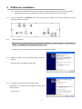
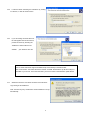
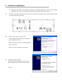
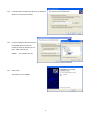
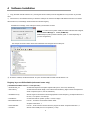
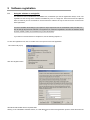
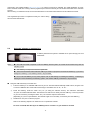
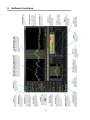
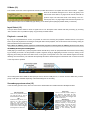
®
AR-IQ
Receiver Control, I/Q Record & Playback
for AR-ALPHA
AOR Ltd.
Authority On Radio Communications
Introduction
AR-IQ software allows direct control of the AR-Alpha receiver through a graphical interface. The recorded samples are
acquired through the USB I/Q Port and further processed (filtered and demodulated) by the PC CPU. All commands are sent to
the AR-Alpha through the receiver’s remote control USB port.
AF vs. I/Q
Compared to a regular AF recording, which only allows recording one frequency at a time, I/Q recording allows you to store and
playback a full 1MHz bandwidth with no loss of quality!
This 1MHz bandwidth can be anywhere within the receiving range of the AR-ALPHA, between 10kHz and 3.5GHz.
Off-line, you can listen and decode within the recorded 1MHz range, tuning any frequency as you would in real time. You can
even loop a particular time frame to listen repeatedly to a signal received in difficult conditions, or search for and analyze hard
to catch signals bursts.
I/Q on the move#
It is also possible to move the I/Q data to another PC and to listen/decode it off line, as long as the other PC has the AR-IQ
software installed as well (see software registration chapter 5). Although AR-IQ data can be copied to any data storage device
(USB key, DVD, external hard-drive, etc:), the data must be first copied to the hard drive of the other PC for AR-IQ software to
work properly. It will not work if the I/Q data is read from a DVD, USB key or through a network, since the read speeds would be
too slow.
1
Table of contents
Introduction :::::::::::::::::::::::::::::::::::::::::::::::::..1
1
Minimum system requirements:::::::::::::::::::::::::::::::::::.:. 3
2
USB driver installation :::::::::::::::::::::::::::::::::::::::: 4
3
I/Q driver installation :::::::::::::::::::::::::::::::::::::::::7
4
Software installation ::::::::::::::::::::::::::::::::::::::::... 9
5
Software registration ::::::::::::::::::::::::::::::::::::::::.10
6
5.1
Using the software on a single PC ::::::::::::::::::::::::::::::::::.10
5.2
Using the software on multiple PCs ::::::::::::::::::::::::::::::::::11
Software functions :::::::::::::::::::::::::::::::::::::::::.12
2
1
Minimum system requirements
●
2.5 GHz Dual Core CPU with 1GB RAM
●
Two available USB 2.0 High-Speed (480Mbit/s) ports. (Three ports if the USB-key license system is used)
●
16 bit AC-97 compatible audio board
●
1024 x768 minimum resolution video board and monitor
●
2 button wheel mouse
●
10 GB or more internal hard-disk
●
Supported OS: Windows 2000 SP4, Windows XP SP2, Windows Vista, Windows 7
Note: The above specifications are for reference only and might vary depending on your PC system.
3
2
USB driver installation
◆ All following screenshots were made using Windows XP. Messages appearing on screen may differ slightly
depending on which version of the Windows operating system and which driver version is used.
2-1
Connect a USB cable to the REMOTE 1 socket on the rear panel of AR-Alpha, and to a spare USB socket on the PC.
(Cable type “USB-A to USB-B”)
2-2
Switch AR-Alpha on.
MAKE SURE THAT IN THE RECEIVER’S CONFIGURATION MENU, YOU HAVE “REMOTE 1” SELECTED FOR
“SERIAL”, OTHERWISE THE USB CONNECTION WILL FAIL.
Windows detects the new hardware and begins the driver installation procedure.
2-3
Windows is asking to connect to Windows Update to search for
software.
Select “NO, NOT THIS TIME” and click “Next”.
2-4
By default, Windows will select “Install the software
automatically”, but you need to select “Install from a list or specific
location” instead.
Then click next.
4
2-5
Locate the folder containing the USB driver by clicking
on “Browse”, to find the driver location.
2-6
If you are loading the driver files from
the CD supplied with the AR-ALPHA,
proceed as shown by selecting the
“USB driver” folder inside the CD.
Validate
your selection with “OK”
Note: A newer USB driver might be available at http://www.ftdichip.com/ftdrivers.htm
Click “VCP Drivers”: then select the device number “FT232B”. Download the zip file and unzip it to
the folder of your choice. This is then the folder you have to locate in the hardware update wizard.
2-7
Windows informs the user about the status of the Windows
Logo testing of this USB driver.
Click “Continue Anyway” and allow the driver installation to set up
automatically.
5
2-8
Click “Finish”.
The USB driver is now installed.
6
3 I/Q driver installation
◆ All following screenshots were made using Windows XP. Messages appearing on screen may differ slightly
depending on which version of the Windows operating system and which driver version is used
3-1
Connect the other USB cable to the I/Q OUT socket on the rear panel of AR-Alpha, and to a spare USB socket of the
PC. (Cable type “USB-A to USB-B”)
3-2
Make sure AR-Alpha is switched ON.
Windows detects the new hardware and begins the
driver installation procedure.
Windows is asking to connect to Windows Update to
search for software.
Select “NO, NOT THIS TIME” and click “Next”.
3-3
By default, Windows will select
“Install the software automatically”, but you need to
select “Install from a list or specific location” instead.
Click next.
7
3-4
Locate the folder containing the I/Q driver by clicking on
“Browse”, to find the driver location.
3-5
If you are loading the driver files from the
CD supplied with the AR-ALPHA,
proceed as shown by selecting the “IQ
driver” folder inside the CD.
Validate
3-6
your selection with “OK”
Click “Finish”.
The I/Q driver is now installed.
8
4
①
Software Installation
Copy the folder “AR-IQ software v.X” (“X” being the version number) from the supplied CD to any location in your hard
drive
② When first run, the software will ask you about the COM port to which the AR-Alpha USB Remote Control is connected.
After the first run, local settings will be saved in the windows registry.
Possible error message, if the COM port number you entered is incorrect
Solution: In order to find out which COM port number Windows has assigned,
check the Device Manager’s “Ports (COM&LPT)”.
USB Serial port (COM x) will be indicated. (Note: “x” varies depending on
your PC configuration.)
The example screenshot below shows that COM8 has been assigned for the COM port.
③ To start the software, double click the file “ar-iq.exe” located inside the folder “AR-IQ software v.X”
Registry keys not GUI editable (advanced users only)
( HKCU¥Software¥Microtelecom s.r.l.¥ar-iq¥v1.0¥ )
- AGCRiseTime_ms
Controls the response of the spike rejection filter (min=5, max=100, default=25).
- AudioLatency
Controls the audio buffer length; lower values minimize latency, higher values are required for
slower computers (min=4, max=20, default=9).
- AutoModeCountry
Sets the region for automatic mode change (based on tuned frequency). Accepted values are 0
for USA, 1 for Japan or 2 for Europe.
- LevelBarPos
Controls the level bar position (0=left, 1=center, 2=right).
- MouseWheelReverse
If set to 1, inverts the mouse wheel rotation effect.
Accepted values are 0, 1.
- PowerOffOnExit
If set to 1, shuts down the receiver when the program is exited. Accepted values are 0, 1.
- VcomPort
Sets the virtual COM port for CI-V operation (1..255).
9
5
5-1
Software registration
Using the software on a single PC
The software is free for unlimited use on a SINGLE PC, nevertheless you need to register after 30 days of use. The
registration is free as long as the software is installed only once on a single PC. The license issued as explained
below, is locked to your PC’s hardware ID. For this reason the software can only be used on the PC on which it has
been registered to.
Your PC’s hardware ID will change if you replace a major component such as motherboard, CPU, hard disk, etc:
This ID change will prevent the software to recognize the PC it has been registered to and thus the software will fail
to launch. Please contact us for assistance if you face this situation
If you intend to use this software on multiple PCs, see the following chapter 5-2.
To show the registration form, click on the blue icon in the top left corner of the application
This window will pop-up.
Click the “Register” button.
All fields should be filled with the requested data.
Clicking on the “REQUEST LICENCE” button, an e-mail will be sent for the license generation process. Users will receive the
10
license file in the supplied mailbox within a few days. If no Internet connection is available, the “SAVE REQUEST TO FILE”
button should be used, thus creating a text file (regdata.txt) that must be manually sent via email to the dealer for the activation
process.
After receiving a confirmation email, save the mail attachment in the same folder where the AR-IQ software is located.
If the registration procedure is completed correctly, the “About” dialog
window should look like this.
5-2
Using the software on multiple PCs
A USB-key based license system is available as an option through your local
AOR dealer.
Note:
●
One USB 2.0 socket is required to use the USB-key license system, as it needs to be inserted every time the
software is used.
●
This USB-key is unique and cannot be reproduced.
●
The license information data inside the USB-key is hidden on purpose and cannot be backed-up. If you lose or
damage the USB-key, a new USB-key needs to be purchased.
●
Do not use this USB-key for any other purpose such as data storage. Formatting the USB-key , overwriting or
deleting its content will destroy the licensing system, and another USB-key would have to be purchased.
■ Using the USB license-key for the first time:
① Insert the USB-key in an available USB socket of your PC. Windows will automatically install a driver, recognize it as
a common USB flash drive named AR-IQ and assign a drive letter such as “D:”, “E:” etc:
② Inside the USB-key, locate the folder “ar-iq v.X” (“X” being the software version). The software’s executable
“ar-iq.exe” is located inside this folder. The software can either be run directly from the USB-key, or from any location
on your PC hard drive, providing the folder “ar-iq v.X” has been copied to that location.
(Depending on your PC’s specifications, the software might not run smoothly if run directly from the USB key.)
③ Double click “ar-iq.exe” to start the program.
Refer to the following chapter 6 for details on how to operate the software.
Do never record I/Q data directly to the USB-key! Chose a location on your hard drive instead.
11
6
Software functions
12
Attenuators (1)
Attenuators allow you to attenuate the input signal by a preferred amount. Users can choose among 0, 10 and 20 dBm
attenuation. The “Auto” button enables automatic attenuation, based on the current input signal level.
Front-End (2)
In the front-end sections, users can control antenna input and select preamp operation. Preamplificator is on when the button is
lit. “Ant.1” and “Ant.2” buttons allow selecting the desired antenna input. If the optional AS5001 antenna switch is present, it's
possible to select antenna input 3 or 4 clicking on the “Ant.Ex” button. The currently used antenna button will be lit.
Main spectrum window controls (3)
Under the main spectrum window, there are 10 buttons that allow user customization of the software. “Spect” button shows line
spectrum view, while “Wfall” enables waterfall view. Users can reverse waterfall direction by clicking again on the “Wfall” button.
While in waterfall mode, the “Palette” button will be selectable and clicking on it will pop-up a new window that allows palette
selection among 9 predefined palettes.
“NBW” and “NBN” buttons control noise-blanking filters and operate at different stages. “NBW” enables a wideband noise
blanker working on the full bandwidth range, before demodulation and any other signal processing; “NBN” enables narrow
band filtering.
“Afc” enables automatic frequency control (tuning); if enabled, the demodulator will tune the frequency automatically, trying to
track small frequency changes in the source signal. This operation mode is only available in FM mode.
“Mono” button is only selectable in WFM mode and forces single-channel audio decoding even if a stereo carrier is detected.
If “Labels” is selected and enabled, the main spectrum view will also show a dBm amplitude scale; moreover, a frequency and
amplitude indicator will follow the mouse pointer while hovering on the main spectrum window in both spectrum and waterfall
mode.
If “PeakSrc” is also selected, the indicators will snap to the highest peak close to the current mouse position.
If “Auto” is enabled, the software will choose the preferred demodulator and filter settings, depending on the currently tuned
frequency and area (Europe, Japan, USA).
Demodulation (4)
The software allows many demodulators, selectable by clicking on the desired button. “AM” selects amplitude modulation
demodulator. Synchronous demodulation is also possible, by selecting the “SAM“ button. “RTTY” and “CW” are
self-explanatory; the demodulators will produce a tone when receiving signals. “LSB” and “USB” refer to lower and upper
sidebands; these demodulators allow the decoding of AM signals with a suppressed sideband. “FM” and “WFM” demodulators
will decode frequency-modulated signals, and in particular the “WFM” mode will allow 260 kHz wide filtering. “DRM”
demodulator will output an 8 kHz IF DRM signal on a virtual audio cable (only if third-party software VAC is installed http://software.muzychenko.net/eng/vac.html ); for optimal DRM demodulation, it's best to set the AGC block to “Slow”. “USER”
demodulation simply outputs on the VAC zero-IF I/Q samples, after filtering and normalization with current AGC settings.
Amplitude (5)
While in spectrum mode, users can select a preferred reference level and view scale, clicking on the arrows available on the
right side of the “Ref Lev” and “Scale” indicators in the “AMPLITUDE” section.
13
Frequency and tuning (6)
This indicator always shows the current tuned frequency. If the operation mode is not set to “Center” (in the “IF FILTER”
section), the AR-Alpha frequency can be different; frequency shift in this case is made by the software. The current frequency
can be tuned using the mouse wheel while hovering with the pointer on the desired frequency digit. Double clicking on the
frequency indicator, a dialog window will appear, allowing direct frequency input. Frequency can also be tuned dragging the
main spectrum window (clicking with the left mouse button and moving the mouse left/right while on the main spectrum
window).
Main spectrum view
Mouse
If not in “Center” mode, the grey bar can be dragged
drag
on the waveform.
In “Center” mode, the receiver will tune to the
Double
requested frequency. Otherwise, software frequency
click
Mouse
wheel
Secondary spectrum view
Fine tuning can be done dragging
the waveform (a red vertical line
downwards depending on wheel rotation direction and
No effect.
shows current position).
The software will tune to the selected
The direct frequency input
frequency.
dialog will pop up.
shift will be used to tune the requested frequency.
Currently tuned frequency will be shifted upwards or
Frequency indicator
Filter width (highlighted as a grey
zone) will vary symetrically.
value set in the “Wheel Step” box.
Currently hovered frequency
digit changes according to
mouse wheel rotation.
Waterfall controls (7)
On the right side of the software window, there are three sliders that control waterfall appearance. From the top to bottom, the
sliders control: waterfall speed, brightness and contrast. They can be operated by dragging the slider or using the mouse wheel
while hovering over the controls.
Span (8)
It's possible to select the desired frequency span by clicking on the arrow buttons in the Span field. The smaller the span, the
slower the main spectrum window will refresh.
FFT Resolution (9)
“Time”, “Mix” and “Freq” allow you to select the desired FFT characteristics, preferring update rate or FFT spectral resolution.
Volume control (10)
“AF Vol” controls output volume. Clicking on the button, the output can be muted; the slider controls volume output level. In
“DRM” and “USER” mode there is no sound card output (all data is redirected to the Virtual Audio Cable).
IF Filter (11)
The “IF Filter” section allows selecting the AR-Alpha I/Q output bandwidth. The “Center” button forces the currently
demodulated signal to be in the center of the main spectrum windows (and disables the software frequency conversion block).
If not selected, all viewable frequencies are tunable without changing the AR-Alpha tuned frequency (through software
frequency conversion).
14
S-Meter (12)
The S-Meter shows the current signal level and also provides the means to set squelch and auto mute functions.
Squelch
level can be enabled clicking the bar in the S1-S9 (green) zone
with the left mouse button; any signal under the set value will not
produce output. The Auto Mute level is set clicking in the S9 S9+70 (red) zone; any signal higher than the limit will produce no
output. Both functions can be disabled by right clicking on the limits symbols (triangles painted directly on the bars).
Input Select (13)
The input select section allows a choice of signal source. The “AR-Alpha” button selects real time processing; by choosing
“Wav” and then “File” it's possible to replay any previously recorded session.
Playback – record (14)
By using the “Playback/Record” section, it's possible to control the recording and playback software features. The square
button stops both playback and recording; the triangular button starts playback; the circular button starts recording, asking for
path and filename before the actual start.
Note: When the USB-key license system is used and the program run directly from the USB key, be sure not to chose
the USB key to store your recording data!
While playing a recorded file, a yellow progress indicator bar will fill up. Users can jump backward and forward in the recording
by just clicking on the bar. It is also possible to repeat a segment, simply by highlighting it with the mouse (i.e. clicking on the
beginning and holding the left mouse button down, moving the mouse pointer to the end of the desired segment and finally
releasing the mouse button). The software will repeatedly decode the selected segment until another click on the bar is issued
or the stop button is pressed.
I/Q recording takes about 700MB of disk space per minute, which is 42GB per hour, or 1TB for 24 hours. Make sure you have
plenty of disk space available depending of the desired length of the recording.
Secondary spectrum view (15)
In the secondary spectrum view, users can fine-tune the selected filter and enable Notch and AM Rejection filter.
Notch Filter
If Notch is selected, double clicking on
any frequency will enable the filter.
Attenuation is tunable using the mouse
wheel. Filter center can be dragged with
the left mouse button.
Filters Bandwidth
There are 8 predefined bands.
The 240 kHz filter is used in
WFM demodulator mode only.
PBT
PassBand Tuning allows you to
fine-tune the filter passband
using the mouse wheel or
dragging the filter edges (using
the left mouse button). The right
mouse button allows dragging
both edges at the same time.
AM Rejection
AM Rejection can be enabled by holding
SHIFT and double clicking on the
desidered frequency in the secondary
spectrum window. A red line will show
the current setting. The filter can be
disabled holding SHIFT while right
clicking on the secondary spectrum
window.
15
Averaging (16)
Main and secondary spectrum display averaging can be enabled by clicking on the button over the respective sliders. Slider
positions set the number of averages used, the higher the slider position (and, as a consequence, the number of averages), the
smoother the spectrum views.
AGC (17)
The automatic Gain Control block has 5 operational modes: “SpkRej” is spike rejection mode; “Fast”, “Med” and “Slow” refer to
the gain variation speed. By selecting “Off”, the AGC processing block will be bypassed and the output level will be manually
adjustable using the volume slider.
Markers (18)
The software allows placing 4 markers on the displayed frequency range. Markers can be set by right- clicking on any
frequency in the main spectrum window; indicators will appear in the top right corner of the main spectrum view. “Clr” button
removes all markers, while “Delta” button enables differential measures among markers, using the first one as reference.
16
®
AOR Ltd.
Authority On Radio Communications
2-6-4 Misuji, Taito-ku, 111-0055 Tokyo, Japan
www.aorja.com
[email protected]
17
April 2, 2013