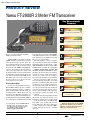
1
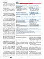
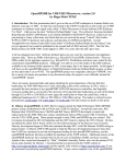
www.rv3apm.com/rxdx.html PRODUCT REVIEW Yaesu FT-2900R 2 Meter FM Transceiver Key Measurements Summary SINAD 0.25 0.2 0.1 Receiver Sensitivity (12dB SINAD, µV) , 89@10 MHz 90 Rx 60 Receiver 3rd-Order Dynamic Range (dB) , 67@20 kHz* 70 Rx 40 Receiver 3rd-Order Dynamic Range (dB) Reviewed by Howard Robins, W1HSR ARRL Contributing Editor The FT-2900R is very similar to the FT2800M and replaces it in the Yaesu Amateur Radio product lineup.1 At first glance the most significant difference is increased high power from 65 to 75 W. On the front panel, the positions of the POWER and WIRES buttons have been swapped, the stenciling on some of the other buttons has changed and the front panel lines are a bit smoother. When I compared the manuals for both radios, however, I discovered that the FT-2900R manual had 30 more pages. So, there is a bit more to the new rig that is not so obvious and some neat features have been added. Physical Description As with other Yaesu mobile transceivers, the FT-2900R is built on a massive cast aluminum heat sink and does not use a cooling fan. There is nothing dainty about this radio, and I would bet that it could be driven over and never skip a beat. Normally, I would be cautious not to drop a delicate instrument for fear of damaging it. If I dropped the FT-2900R on my ceramic tile floor, I think the floor would 1J. Carcia, NJ1Q, “Yaesu FT-2800M 2-Meter FM Transceiver,” Product Review, QST, Jun 2003, pp 63-65. Past QST reviews are available to ARRL members at www.arrl.org/product-review. be the loser. I have been using an FT-2800M to send APRS weather beacons every 10 minutes for more than two years and it keeps on going. These are very rugged radios. The front panel has a large six digit liquid crystal display (LCD) with controllable backlighting. There are three knobs — VOLUME and SQUELCH on the left and the MAIN TUNING dial on the right. Six push buttons — POWER, WIRES/LOCK, SET/MHz, DW/ REVERSE, A/N/LOW and MW/D/MR are below the display. It’s obvious what several of these controls are used for. I will explain the less obvious ones in this review by example. I have used radios with more cryptic labeling. The rear panel SO-239 RF connector is recessed and partly shrouded by an extended part of the cast aluminum body. The external speaker jack is recessed in the lower left corner next to the power pigtail. Note that there is no data port on this radio. You would need to use the external speaker and mic jacks to interface with your TNC or other data device and adjust the squelch and volume levels accordingly. There is a bottom-firing internal speaker that sounds crisp and loud enough to me. Lab testing showed plenty of audio output — nearly 4 W. The mic is the MH-48 with keypad that comes packed with most new Yaesu VHF radios. This mic permits users to safely control many of the FT-2900R’s features and functions and uses an RJ-45 connector. Mark J. Wilson, K1RO Product Review Editor ChRej 50 67 IF 60 Img 60 Snd 1 T-R 250 pr050 90 Adjacent Channel Rejection (dB) 101 135 IF Rejection (dB) 76 120 Image Rejection (dB) Audio Output (W) 3.8 4 116 50 Tx-Rx Turnaround Time (ms) Key: * Measurement noise limited at value shown. Bottom Line Sturdy and powerful, the FT-2900R has all of the features we’ve come to expect in a 2 meter transceiver and adds some useful new ones. [email protected] September 2010 39 Programming Yaesu offers an optional USB cable and Windows software for programming channels and settings on this radio (part number ADMS-2900). I did not use this software, but if you plan to load up the radio’s 200 memory channels or change them frequently, you might consider it. I found that after about five minutes of self training, manual programming is fairly simple. It took about 10 minutes to program 10 channels with repeater parameters — receive frequency (split is automatic), tone frequency, tone type and channel name. Step one is to repeatedly press the MW/D/ MR button until VFO is displayed on the LCD. Then turn the frequency knob or use the microphone keypad to enter the receive frequency. Next, pressing the SET/MHz button for a second brings up an alphabetically ordered and numbered menu of settings (menu mode). Use the large knob to scroll through the menu items until TN FRQ (tone frequency) is displayed. Press the SET/MHz button to select this item, turn the large knob to scroll to the appropriate subaudible tone and press the SET/MHz button again to set the selection. The tone frequency is now set. To set the tone type, while still in the menu mode turn the large knob to SQL.TYP. Press SET/MHz, select TONE from among TONE/ TSQL/DCS/RV TN/OFF and press SET/MHz again. This last action displays a T on the LCD, indicating that TONE is on. Pressing and holding SET/MHz again exits the menu mode. At this point, all the repeater parameters are set in the VFO buffer. Press and hold the MW/D/MR button to get into the memory storage mode. The next available channel number blinks on the LCD. Press and hold the MW/D/ MR button again to write the contents of the VFO buffer into the memory channel. You could select a different channel to write to by turning the large knob. Next, enter a name for the memory channel. Repeatedly press the MW/D/MR button until MR is displayed on the LCD, indicating that the radio is in memory read mode. While in this mode, press the SET/MHz button, and scroll to NM SET, press the SET/MHz button again to enter a channel name one letter at a time. Turn the large knob to scroll through the character set. Press the SET/MHz button to set each character. Press and hold SET/ MHz again to exit the menu mode. Although this procedure may sound tedious, it’s easier to do than describe — and easier yet with the optional software. This example should give you a good sense of what’s required to set up the many features in this radio. Menu mode operation is fundamentally consistent, and the method to turn on and customize features is the same. However, some buttons on the FT-2900R are used differ40 September 2010 Table 1 Yaesu FT-2900R, serial number 9I041737 Manufacturer’s Specifications Measured in ARRL Lab Frequency coverage: Receive, 136-174 MHz; transmit, 144-148 MHz. Receive and transmit, as specified. Modes: FM, NFM. As specified. Power requirements: Receive: <700 mA, <300 mA (standby); transmit, 15, 9, 5, 4 A (high, low 3, low 2, low 1) at 13.8 V dc ±15%. Receive, 760 mA (max volume, max lights, no signal); standby, 160 mA (no lights). Transmit, 14, 8.9, 5.5, 4.3 A (high, low 3, low 2, low 1). Receiver FM sensitivity: 12 dB SINAD, <0.4 µV. Receiver Dynamic Testing For 12 dB SINAD, 0.2 µV; 0.2 µV at 138 MHz, 0.21 µV at 162 MHz. FM two-tone, third-order IMD dynamic range: Not specified. 20 kHz offset: 67 dB*; 10 MHz offset: 89 dB. FM two-tone, second-order IMD dynamic range: 146 MHz, 92 dB. Not specified. Adjacent-channel rejection: Not specified. 20 kHz offset: 67 dB. Spurious response: Not specified. IF rejection, 101 dB; image rejection, 76 dB. Squelch sensitivity: Not specified. At threshold, 0.07 µV; 0.27 µV max. S meter sensitivity: Not specified. 4.2 µV at full scale. Audio output: 3 W at 10% THD into 4 W. 3.8 W at 10% THD into 4 W; THD at 1 V RMS, 1.5 %. Transmitter Power output: 75, 30, 10, 5 W (high, low 3, low 2, low 1) at 13.8 V dc ±15%. Transmitter Dynamic Testing 71.4, 27.4, 7.7, 3.8 W (high, low 3, low 2, low 1); 69.7 W at 11.4 V dc. Spurious signal and harmonic suppression: >60 dB. >70 dB, meets FCC requirements. Transmit-receive turnaround time (PTT release to 50% of full audio output): Not specified. Squelch on, S9 signal, 116 ms. Receive-transmit turnaround time (“tx delay”): Not specified. 132 ms. Size (height, width, depth): 1.6 × 5.5 × 5.7 inches; weight, 2.6 pounds. Price: FT-2900R, $160; ADMS-2900 programming software/cable, $50. *Measurement was noise limited. ently depending upon feature, so the owner’s manual may become your best friend. New Features The FT-2900R includes several new features shared with the latest generation of Yaesu VHF/UHF FM transceivers. A few are proprietary to Yaesu, which may make them useful only if your friends have compatible radios. Enhanced Paging and Code Squelch (EPCS) EPCS uses a dedicated microprocessor and paging memory to provide paging and selective calling features. Two CTCSS (continuous tone coded squelch system) tone pairs are used — one pair for sending and another for receiving. A tone pair is sent to the receiving station when paging. If the tone pair matches those stored in the receiving radio, its squelch will open. You could use the same tones in several radios for closed group calling or unique tone pairs to page individual radios. This coded squelch system could be used to keep your radio quiet until calls directed only to you are received. While the radio is squelched, you cannot hear activity on frequency. So, before initiating a page, listen to make sure the frequency is not in use. This feature can be used to make a bell ringing sound when your tone pair is decoded. The number of rings is settable. EPCS settings can be saved to individual memory channels, so once programmed, it is pretty simple to use this feature when you want to. For public service activities you could have different transmit tone pairs on different channels (with all other settings the same) to page different groups or individuals participating in your activity. Memory Bank Operation This feature lets you group channels that are not necessarily sequential. For example, I have my programmed channels 5, 11 and 13 assigned to bank 1. There are eight banks available, and the same channels can be as- signed to as many banks as you need. With 200 channels this feature could come in handy, especially if you are on the road and want to group your channels by areas that you travel. You can use this feature to manually select channels within the bank or to scan just the selected bank channels. Banks can be selectively linked for scanning. This is a pretty flexible radio. displayed. After the radios are back in range, normal beeps return and IN RNG is again displayed. You can even set this radio up to send your call sign in CW every 10 minutes to assure compliance with identification requirements. While the ARTS feature is active, other functions are locked to prevent inadvertent changes and loss of contact. Automatic Range Transponder System (ARTS) The weather alert scan monitors for NOAA’s 1050 Hz tone alert — this can be optioned on or off. After turning this feature on, the weather broadcast channels are checked for activity every five seconds. I can set the FT-2900R to scan a memory bank to monitor those frequencies, while also having the weather broadcast bank scanned every five seconds. All scanning can be observed on the LCD, including the excursions to the weather memory bank. I observed that even though there may be activity on a weather channel — indicated by a full scale S-meter reading — without the alert tone, scanning does not stop. The FT-2900R also includes password protection, busy channel lock-out, a CW training feature and WiRES (Wide-Coverage The ARTS feature uses DCS (digital coded squelch) signaling to alert parties with this capability that they are within simplex communication range of each other. When activated, a DCS code is transmitted for 1 second every 25 seconds (or optionally, every 15 seconds), or when the PTT is pushed. Other radios with this feature activated and within range can sound an audible beep (if enabled) and display IN RNG on the LCD. If out of range, OUT RNG will be displayed and polling signals will continue until the ARTS feature is deactivated. Three beeps will sound if you go out of range for more than one minute and OUT RNG will be Weather Band/Weather Alert Internet Repeater Enhancement System) capability. These features were described in the May 2010 review of the FT-1900R.2 The Owner’s Manual I own radios from most of the manufacturers and have reviewed a few others, so I have read through many different manuals. The FT-2900R has some typical and not so typical capabilities, and I found its manual to be very well written and illustrated. It does a great job of explaining how the features could be used, and how to activate and deactivate and set options for them. The FT-2900R is a fine heavy duty 2 meter radio with lots of power and some very nice features. I particularly like the memory bank, password protection and weather alert features and would use them routinely. Some of the features, EPCS and ARTS for example, would be useful in specialized applications. Manufacturer: Vertex Standard, 10900 Walker St, Cypress, CA 90630; tel 714-8277600; www.yaesu.com. 2S. Ford, WB8IMY, “Yaesu FT-1900R 2 Meter FM Transceiver,” Product Review, QST, May 2010, pp 47-49. www.rv3apm.com/qs1r.html SRL QS1R Software Defined Receiver Reviewed by Martin S. Ewing, AA6E ARRL Laboratory Small software defined radio (SDR) receivers are developing into an Amateur Radio industry category. The QS1R “Quicksilver” radio (Revision D); from Phillip Covington, N8VB, of Software Radio Laboratory, is one of the latest and most powerful. QST has previously reviewed the Microtelecom Perseus, the RFSpace SDR-IQ, and the more specialized Telepost LP-PAN Panadapter.1-3 If you combine most of these SDR radios with a personal computer and the right software, you have a complete general coverage communications receiver with “panoramic” spectrum display. The QS1R supports a wide range of applications, from amateur and SWL listening, to interference diagnosis and laboratory measurements. It features wide instanta- neous bandwidth and a very flexible signal processing scheme built around a large field programmable gate array (FPGA). Hardware When you purchase the QS1R, you receive a small black box, a USB cable, an 1S. Ford, WB8IMY, “Microtelecom Perseus Software Defined Receiver,” Product Review, QST, Dec 2008, pp 40-44. QST Product Reviews are available to ARRL members at www.arrl.org/product-review. 2S. Ford, WB8IMY, “RFSpace SDR-IQ Software Defined Receiver,” Product Review, QST, Feb 2010, pp 49-51. 3J. Hallas, W1ZR, “TelePost LP-PAN Software Defined IQ Panadapter,” Product Review, QST, Feb 2009, pp 45-47. Bottom Line The Quicksilver QS1R software defined receiver offers a number of interesting advanced possibilities in addition to use as a flexible general coverage receiver. optional 5 V wall mount supply, a short list of instructions and that’s it for your hefty investment. The picture improves if you look at the product Web site (qs1r.wikispaces.com) and Internet support group (groups.yahoo. com/group/qs1r/). Download the software (QS1RServer and SDRMAX-II, discussed below), load up your PC and you’re in business. The instructions are a bit minimal, but if you have middling computer or SDR experience, there should be no trouble. If you are SDR challenged, you will get a lot of patient help through the Internet support group. Still, more complete new user documentation would be welcome. Inside the box, the QS1R is a single PC September 2010 41 Table 2 Software Radio Laboratory QS1R, Rev D, serial number 100027 dard internal clock, a software adjustment allows you to precisely zero beat WWV or other frequency standard. Manufacturer’s Specifications Measured in the ARRL Lab Frequency coverage: 10 kHz-62.5 MHz As specified. Frequency Aliasing Power requirement: 5-6 V dc, 1A. At 6 V dc, 900 mA (minimum volume); 910 mA (maximum volume).* Modes of operation: SSB, DSB, CW, AM, SAM, FM, WFM. As specified. Receiver Sensitivity: 0.63 μV SSB at 10 dB (S+N)/N. Receiver Dynamic Testing Noise floor (MDS), 500 Hz filter: 0.137 MHz –114 dBm 0.505 MHz –117 dBm 1.0 MHz –117 dBm 3.5 MHz –118 dBm 14 MHz –118 dBm 50 MHz –118 dBm Noise figure: Not specified. 14 MHz, 29 dB AM sensitivity: Not specified. 10 dB (S+N)/N, 1 kHz tone, 30% modulation, 6 kHz bandwidth: 1.0 MHz 8.13 µV 3.8 MHz 7.08 µV 50 MHz 8.80 μV FM sensitivity: Not specified. For 12 dB SINAD: 29 MHz 2.51 µV 52 MHz 3.09 µV Spectral display sensitivity Not specified. –123 dBm. Blocking gain compression: Not specified. Gain compression, 500 Hz bandwidth:** 20 kHz offset 5/2 kHz offset 3.5 MHz 122 dB 122/122 dB 14 MHz 122 dB 122/122 dB 50 MHz 122 dB 122/122 dB Reciprocal mixing (500 Hz BW): Not specified. 20/5/2 kHz offset: better than 122 dBc.† FM two-tone, third-order IMD dynamic range: Not specified. 20 kHz offset: 29 MHz, 56 dB; 52 MHz, 57 dB. Spurious free dynamic range: 112 dB. 100 dB. S-meter sensitivity: Not specified. S9 signal at 14.2 MHz: 50.1 µV. Squelch sensitivity: Not specified. 29 and 52 MHz, 0.6 µV. IF/audio response: Not specified. Range at –6 dB points (bandwidth):‡ CW (500 Hz filter): 302-800 Hz (498 Hz). Equivalent Rectangular BW: 481 Hz. USB (2.4 kHz filter): 73-2384, 2311 Hz. LSB (2.4 kHz filter): 73-2383, 2310 Hz. AM: (6 kHz): 72-2809 (one sideband; 5474 Hz for both sidebands). Size (height, width, depth): 2.0 × 4.1 × 6.4 inches; weight, 14.1 ounces. Price: QS1R receiver, $999.99; power supply, $19.99. *Depends on amount of processing in use; 1.5 A when used with Skimmer Server software. **Blocking level exceeds the threshold of ADC clipping. †No reciprocal mixing occurred up to ADC clipping (+4 dBm). ‡Adjustable with DSP. board as shown in the lead photo. The external connections include a BNC antenna jack, an SMA jack for optional external clock, a USB jack, audio output and a 5 V power jack. An 8-pin DIN jack provides I/O connections for planned additional devices, to include a front end amplifier/pre-selector and a transmitter module. The QS1R board has only three major ICs — a 16-bit 130 megasample per second (MSPS) analog to digital converter (ADC), a Cyclone III FPGA and a microcontroller. 42 September 2010 The controller and FPGA are initialized at power up by the QS1RServer program running on your PC. At the board level, the QS1R has several interesting features you can use to go beyond basic ham applications. With a minor board modification, you can clock the ADC, which normally runs at 125 MHz, from an external source at any frequency between 1 and 130 MHz. This lets you sync the receiver to an external frequency standard if you need high accuracy or stability. Even with the stan- When an SDR samples the input at 125 MHz, you would want a low pass filter at the radio’s input to reject any signal above about 62.5 MHz, the Nyquist frequency.4 Without the filter, any signal above 62.5 MHz will be aliased into the 062.5 MHz “baseband.” The ADC operates like a mixer with a local oscillator (LO) at 125 MHz and harmonics of 125 MHz. The QS1R’s input low pass filter is relatively flat up to 62 MHz and falls off by 20 dB at about 75 MHz. The good news is that you can receive signals up to 62.5 MHz with full sensitivity. The bad news is that signals (and noise) at a frequency, f, between 62.5 MHz and 125 MHz, may be visible at an apparent frequency 125 – f MHz. For example, the FM broadcast band limits 88 and 108 MHz alias to 37 and 17 MHz, respectively. At the ARRL Lab, we verified that many strong local FM stations were clearly received in the 17 to 37 MHz range when we connected to a GAP Titan vertical antenna. They were attenuated but might cause you problems above 18 MHz. Frequency aliasing can be used to your advantage, but you may have to provide your own bandpass filter. You can make a small board modification that bypasses the input filter and lets you receive up to 300 MHz or higher in segments of 62.5 MHz. The SDRMAX-II software supports this “undersampling” mode and provides the right frequency scale readings. This receiver provides the demodulated audio on a stereo phone jack, suitable for headphone listening or passing to your PC’s soundcard input. Getting your audio this way (instead of over the USB connection to your PC) gives you flexibility and minimal time delay, but it complicates the picture if you want to use the receiver remotely over a LAN. You would have to find a way to transmit the audio separately from the data channel. The QS1R always samples the entire band from 10 kHz to 62 MHz, and you can display a chunk of spectrum as small as 40 kHz or as wide as 20 MHz. After filtering in the FPGA, a digital output stream of up to 4 MSPS is output from the receiver to your PC. Software Two separate programs run on your PC to support the receiver. QS1RServer talks with the receiver hardware, and loads the receiver’s microcontroller and FPGA 4The Nyquist frequency (half the sampling rate) is the highest signal frequency that can be accepted without aliasing. See en.wikipedia. org/wiki/Nyquist_frequency. The QS1R, Contesters and Skimmer Server Pete Smith, N4ZR I suppose there may still be some active Amateur Radio operators who haven’t heard of CW Skimmer, the amazing, somewhat controversial software written by Alex Shovkoplyas,VE3NEA (www.dxatlas. com). It decodes all the CW signals across a wide slice of a band, decides which ones are CQing and which are answering CQs, and can, if asked, offer “spots” via Telnet and the Internet. DXers use it to find DX on a band, and to figure out where to call in big pile-ups by tracking the successful callers. Contesters use it like traditional “packet clusters” to find people to work and to catch band openings. The QS1R, with its open software architecture, offered Alex a tempting challenge. Instead of listening to one band at a time, could the radio be reprogrammed to listen to many bands simultaneously? Well, it could, and he did. The result was Skimmer Server, software that offers Skimmerstyle decoding on up to seven bands at once, and up to 192 kHz per band. As a result, the QS1R/Skimmer Server combination has captured the attention of contesters and DXers worldwide. Reverse Beacon Network I use my Skimmer Server/QS1R combination both as a stand-alone Telnet server, open to anyone who wishes to log on, and also to contribute to the Reverse Beacon Network (RBN), a worldwide network of Skimmer and Skimmer Server receiving stations (reversebeacon.net). The RBN collects Telnet spots from each connected receiver and passes them to the server, where they are displayed on a constantly changing world map and also archived for future analysis. The amount of information collected is quite spectacular — for example, in the 24 hours of the Russian DX Contest, the RBN collected over 545,000 spots from 34 “reverse beacons” on four continents. So what? To begin with, you can find out what stations or countries have been spotted by the network, when and on what frequencies — like a constantly revised real-time DX bulletin. Thanks to Rick Walker, K4TD, spots from the RBN are also available at telnet.reversebeacon. net, port 7000. You can filter the spot Figure A — The Skimmer Server provides a wealth of information about received stations. Information about software and computer parameters is displayed on the right. stream you receive, just as with a DX Cluster node — only there are many more spots. In addition, a group led by Felipe Ceglia, PY1NB, is hard at work developing other new ways to use the RBN’’s prodigious spot database. The first of these is an online Spot Analysis Tool, written by Nick Sinanis, F5VIH/SV3SJ. Tell it a date, the call signs of several stations to compare and a reverse beacon’s call sign, and it will quickly display comparative graphs of the stations’ signal strength (relative to local noise) on every band. Although fading and interference can invalidate any single comparison, the graphs clearly portray comparative performance — you can use the data for bragging rights, or to plan improvements for “the next time.” Using the Software Back to Skimmer Server. In Figure A, the left hand “pane” is the aggregator, displaying the spots that my station heard and reported (on a simple vertical) in the few minutes before the screen shot was taken. The right-hand “pane” is the Skimmer Server control panel, which I usually keep on the STATUS tab, to tell me how it’s doing in real time. In order to reduce load on the host computer, the Skimmer Server normally operates almost invisibly, as a simple icon in the Windows System Tray, but you can pop this window up to keep track of what it is doing and to change settings if you wish. You’ll note that the control panel tells me that both the Telnet server and the link to the QS1R are working normally, and also how many decoders are currently operating on each band. It reports how much computer power is being used (this was on a relatively quiet Monday morning at 96 kHz bandwidth on seven bands), and other parameters of interest. By the way, the computer on which I’m running Skimmer Server is a relatively basic dual-core Pentium, much slower than the cheapest computers currently on the market from major manufacturers. A quad-core Godzilla is not required. Why are contesters so interested? Well, Skimmer Server spots have some unique advantages over spots from traditional DX clusters. If you connect to a Skimmer Server relatively close to you, you will be able to hear everything it can. It spots everything, not just rare stations, which makes it ideal for contesting, though it can occasionally get confused about which stations are CQing (running in contest parlance). The frequency calibration is consistent, so that all stations are heard at roughly the same pitch as you jump up or down the bandmap, and copy accuracy is at least as good as the DX cluster average. And finally, connecting to a Skimmer Server off-site is an ideal solution for multioperator stations, avoiding the complex engineering required if a CW Skimmer were used in that RF-loaded environment. The Skimmer Server software is part of the CW Skimmer package, available for download from Afreet Software (www.dxatlas.com). The package can be tried free for 30 days and costs $75 to register for continued use thereafter. September 2010 43 Figure 1 — The SDRMAX-II software with QS1RServer behind. c onfiguration. It also detects the desired audio channel. The SDRMAX-II program is the one you work with directly with through its complex graphical interface. The two programs talk to each other using TCP/IP protocols. You normally run both of them in the same PC, but you can place them in separate computers on a LAN — and across the Internet, if your connection is fast enough. (I measured a typical data rate of 333 kbit/s between the programs.) While currently the Windows-only SDRMAX-II is the recommended software, you do have (free) alternatives. They include a “cross-platform” SDRMAX-III that works with Linux, MacOS X, or Windows, and independent software such as Winrad (www. winrad.org) and WinradHD (www.hdsdr. de). Naturally, each program has its strong points. I am a Linux fan, and I appreciate that I can run SDRMAX-III on my Ubuntu system, even if I have to compile it from source. However, I found that SDRMAX-II for Windows was more mature and easier to use. I think it looks better too, but that’s a matter of taste. A major update called SDRMAX-IV is in development. Because SDR is CPU intensive, I wanted to explore how it worked on a small computer. I was able to run SDRMAX-II on my Celeron M (1.5 GHz) laptop, using 40 to 60% of its CPU power. Operation was fairly smooth even on this small machine, especially after I reduced the spectrum update rate. SRL specifies the minimum configuration as a 1.6 GHz Atom 330 CPU with 512 MB RAM (2.5 GHz Dual Core recommended). All the QS1R code from SRL is open source, so if you have the desire and expertise, you can make modifications or even roll your own software. That’s important, even for non-programmers, because developers are likely to provide new capabilities over time. 44 September 2010 Skimmer Server (see the sidebar) is an elegant product developed on the QS1R platform. It takes complete control of the QS1R, bypassing the SRL software. Because this program uses much more of the FPGA’s capability, up to 7 receivers with 192 kHz bandwidth running in parallel, it needs a beefy power supply. Even if you aren’t going to use Skimmer Server, I recommend using a supply with at least 2 A capacity — it leaves your options open for future applications. Learner’s Permit Any advanced radio takes some time to learn, and the QS1R is no exception. The hardware connections are simple, but the SDRMAX-II software definitely has a learning curve to climb. The operating screen is complex, and it is not immediately clear how to do even the basic functions such as tuning. There is no built-in help system, except that tooltips are displayed if your cursor hovers over a particular control. The support Web site offers an online help manual that helps, but it is incomplete. The site’s FAQ list fills in some of the gaps, but you’re going to face a certain amount of trial and error and e-mail consultation! A training video would go a long way toward getting new users up to speed. Joy of the Open Road I enjoyed learning to drive this radio, but the real fun begins when you take it out on the highway. Hooked to my antenna farm (dipoles for 80 and 40 meters plus a three element SteppIR Yagi), its receive performance on the amateur bands was comparable to my Ten-Tec Orion, except for reduced sensitivity on the higher bands. My home location is relatively quiet — no high power transmitters in the area — and the bands were not crowded. For me, the major plus of the SDR is the spectrum display and the waterfall. You can monitor a band segment, a whole band, or even multiple bands (up to 20 MHz of spectrum) to monitor propagation using HF broadcast or amateur stations. The waterfall shows a time history. You can find some very interesting modulation modes, swept frequency radios and ionosondes. You can even do radioscience — watch interference patterns (selective fading) drifting across the sidebands of a distant HF broadcast signal, telling you how ionospheric clouds are moving! There are many other ways you can use the QS1R. You can find a signal with an unknown frequency, such as parasitic oscillations, very quickly. You can diagnose obscure interference issues. Many interference sources have broad spectra that can be a little hard to understand with a narrowband receiver. I discovered that a problem I had been seeing on 10 meters was actually spread out over several MHz, putting me on the track to find some arc-like source. The QS1R would serve as a fine panadapter attached to another receiver’s first IF, but it would be overkill for this relatively narrowband application. You can connect the audio output to your computer’s audio input jack and use any audio analysis program you like. For example, DRM or other digital voice decoders, PSK31, RTTY and other digital data modes should be simple to decode. With its synchronous AM detection, the QS1R makes an excellent AM broadcast receiver. Conclusions There are a few rough edges with this product, which I’ve touched on above. The documentation is incomplete, although the e-mail and Web based help ecosystem is very useful. The receiver sensitivity is relatively low, limiting performance in the higher bands, and the input low-pass filter is not sufficient to prevent aliasing of signals above 62.5 MHz. If all you want is a good general-coverage receiver, there are less expensive products on the market with better specifications. The compelling features of the QS1R SDR have to do with its ability to quickly survey the entire spectrum from 10 kHz to 62 MHz and to provide a very flexible display with point and click signal tuning and setting of bandpass filters. As a panoramic display of one or more entire amateur bands, it can add a lot of capability to your station. It is also a useful piece of test equipment for your bench. On top of that, the QS1R has a lot of untapped horsepower for special applications, as the Skimmer Server product shows. Manufacturer: Software Radio Laboratory, 8776 Shillington Dr, Powell, OH 43065-9001; tel 614-339-4324; www.srl-llc.com. SHORT TAKES CC User DX Cluster Client When someone gushes about a piece of Amateur Radio software and ends the excited tale by saying, “And it’s free, too!” I am instantly skeptical. Throughout my life to date, the ancient axiom “You get what you pay for” has usually proven to be accurate. If something is said to be free, I lower my expectations quite a bit. But axioms aren’t blessed with universal veracity, otherwise they’d become scientific truths like Maxwell’s equations. In the case of VE7CC’s CC User software, the axiom is entirely wrong! What is a DX Cluster Client? A DX Cluster is a network devoted to monitoring on-the-air activity throughout the world. Hundreds of hams are connected at any given time, posting spots with information about signals they’ve discovered on bands from 160 meters through microwave. DX Clusters are an outgrowth of the original DX PacketClusters that performed the same tasks using radio data networks on 2 meters and 70 cm. Some of these PacketClusters still exist, but most Cluster networking has since shifted to the Internet. DX Clusters are popular among contest enthusiasts, DX hunters or anyone else who is interested in keeping their fingers on the pulse of Amateur Radio activity. But many of us, myself included, are often too busy to sit before the computer and sample the action. That’s where the Cluster client comes into play. Cluster clients are software applications that do much of the monitoring for you. They connect to the Cluster of your choice, get the most recent spots, periodically download propagation information and so on. Best of all (at least for me), these clients can filter the torrent of information. For example, if you don’t have the ability to get on 160 meters, you may not be interested in seeing spots for 160 meter activity. Not a problem. The Cluster client can be configured to ignore 160 meter spots. Or, if you are looking for a particular station (such as a DXpedition operation) or a station from a particular DXCC entity, the Cluster client can “watch” for these and alert you if they are spotted. VE7CC’s CC User A number of Amateur Radio logging and The CC User main page. contest applications have Cluster clients built in, but CC User by Lee Sawkins, VE7CC, is a stand-alone program for Windows. It is rich with features, yet surprisingly easy to use. CC User can “talk” to a packet TNC if you prefer to connect via radio, or it can make Internet Telnet connections to your favorite online DX Cluster. For this review I used a Telnet connection, which was simple to set up. CC User includes a list of Telnet Clusters, or you can enter another of your choice. There is a User Info screen that allows you to enter your call sign, Cluster password (if needed), your location, etc. CC User’s filtering features are impressive. Since I tend to operate CW and digital, I set my filter to ignore spots in the phone portions of the bands. I also configured it to only show spots from hams who were in my area of the country (seeing spots from stations on the other side of the continent wasn’t as useful since I may not be able to hear what they are hearing). If a particular spot catches my eye, I can click my mouse cursor on the call sign and look up the station on QRZ. Holding the CONTROL key while clicking my mouse opens a window showing the sunrise and sunset times for that station. CC User keeps an eye on space weather, too. One day I glanced at the screen to find Steve Ford, WB8IMY 50 September 2010 QST Editor a glowing red box announcing Minor Radio Blackouts. No wonder I wasn’t hearing much on HF that afternoon! If you are interested in working stations who participate in ARRL’s Logbook of The World, CC User will request this information and flag these stations in the list. It reminds you to refresh the LoTW database with the appearance of a red highlighted button. The alarm function is excellent. I turn up my computer speakers for a welcome blast of audio whenever a desired station appears. I can even tell CC User to shoot an e-mail message to my cell phone. Use this function with care, though. You don’t want to find yourself interrupting a business meeting to declare that you have to rush home because 6 meters is open. Great Software; Great Price Lee has done an outstanding job with CC User. The layout is clean and direct. He has even built in an auto updater that “phones home” via the Internet and alerts you to download the latest version (Lee is constantly making improvements). The fact that all this functionality comes free of charge is just icing on the cake. You can download the latest version of CC User at www.ve7cc. net. Scroll about 3⁄4 of the way down the page to find the download link. [email protected]