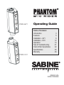
1
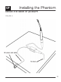
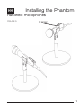
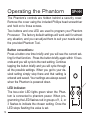
PMR-GP1
Operating Guide
Table of Contents
Introduction
Features
Installation - GP1
Installation - HH1
Operation
Tips & Troubleshooting
Chart of Mic Sensitivities
Specifications
Warranty
3
5
6
12
14
21
22
25
26
PMR-HH1
MADE IN USA
PATENT PENDING
2
Congratulations on getting your new Phantom Mic Rider!
This operating guide covers the use of both models of the
Phantom. Follow the directions that apply to your model.
For your convenience each section of this guide is marked
as follows indicating which model is explained.
GP
PMR-GP1, for gooseneck & podium mics
HH
PMR-HH1, for handheld mics
GP+HH
Both models
The Phantom will improve the sound of your Podium,
Gooseneck, or Handheld mics. Use the Phantom in these
applications: schools, teleconferencing centers, houses of
worship, meeting rooms, etc. The Phantom is not
designed for vocal performance, recording, or broadcast
applications.
3
Your box contains the following items:
4
GP
• One Phantom Mic Rider
• One IR Sensor cord with connector. Some models sold
without this item.
• Eight metal clips in various sizes for attaching the IR Sensor
cable to your gooseneck mic.
• Three plastic clips to attached the IR Sensor to the
gooseneck and one for mounting it under a table or podium.
• One Allen wrench for adjusting the orientation of the
Phantom.
• One small Phillips screwdriver for removing the security
cover.
• One plastic programming Phantom Tool.
• This Operating Guide
HH
• One Phantom Mic Rider with built-in IR sensor
• One small Phillips screwdriver for removing the security
cover.
• One plastic programming Phantom Tool.
• This Operating Guide
Features
Your new Sabine Phantom Mic Rider is the first
phantom-powered DSP unit that provides these five
powerful features:
• FBX Feedback Exterminator
Increases gain before feedback
• Automatic Gain Control
Helps maintain level as you move toward and
away from the mic.
• Proximity Effect Control
Reduces the excess bass sound as you get
closer to the mic - maintains flat frequency
response at all distances from the mic
• Plosive Control
Reduces the loud pops and bursts from certain
consonant sounds in speech
• Infrared Gate
Mutes the mic when no one is in front of it using
the included infrared heat sensor
5
Installing the Phantom
GP
Above the table or podium
1. Mute the audio channel for the microphone you have
selected to use with the Phantom. Remove the mic from the
base or podium and set it aside.
2. Plug the Phantom (PMR-GP1) into the same base
connector as the mic, as shown in Figure 1. The Phantom
requires phantom power - when you plug in the Phantom you
should see the LED turn green indicating phantom power is
present.
3. Plug the microphone into the top of the Phantom. Plug in
the IR Sensor and connect the cable to the gooseneck using
the supplied clips, as shown in Figure 2. For best results
install the sensor and cable with the gooseneck pointed
straight up - this will give enough slack in the cable to account
for any movement while in use.
4. If necessary you can change the orientation of the
Phantom so it conforms to the connector on your mic base or
podium. See the instructions on page 7.
5. Activate (un-mute) the mic and check for normal audio
operation. Turn to the next page and begin the Setup
Procedure.
6
FIGURE 1
Installing the Phantom
FIGURE 2
Connecting IR Sensor cable
7
Installing the Phantom
GP
Changing the Orientation of the Phantom
If necessary you can change the orientation of the Phantom
so it conforms to the connector on your mic base or podium,
as shown in Figure 3.
1. Use the included Allen wrench and loosen the set screws
as shown in Figure 3.
2. Turn the body of the Phantom one half turn clockwise – no
more!
3. Tighten the set screws on both sides of the Phantom case
and be sure they seat into the connector - just like they did
originally. Continue installing as shown in Step 3 on page 6.
8
GP
Installing the Phantom
Changing the Orientation of the Phantom
FIGURE 3
If the Phantom mounts like
this, then loosen the Allen
screws as described on the
previous page.
Turn the Phantom no more than
1/2 half turn clockwise. Tighten
the screws and the Phantom will
be properly oriented.
9
Installing the Phantom
GP
Below the table or podium
(Refer to Figure 4 on next page)
1. Mute the audio channel for the installed microphone you
have selected to use with the Phantom. Working below the
podium or table, remove audio cable from the mic.
2. Mount the Phantom below the table using Velcro or tie
wraps; plug in the IR sensor cable and run that out to the front
edge of the table or podium, as shown in Figure 4. Make sure
the sensor is pointed toward the area where people stand or
sit to use the microphone.
3. Take the cable that was connected to your mic and connect
it to the output (male XLR) of the Phantom. Using another
audio cable (a short one is best), connect the input of the
Phantom (female XLR) to your installed microphone.
4. Activate (un-mute) the mic and check for normal audio
operation. Turn to page 14 and begin the Setup Procedure.
10
GP
Installing the Phantom
Below the table or podium
FIGURE 4
IR sensor and cable
To mixer
11
Installing the Phantom
HH
Handheld microphones
(Refer to Figure 5 on next page)
1. Mute the audio channel for the handheld microphone you
have selected to use with the Phantom. Remove the audio
cable from the mic.
2. Plug the Phantom (PMR-HH1) into the microphone as
shown at right, and reconnect the audio cable.
3. The Infrared sensor is built into this version of the
Phantom. Orient the microphone in the holder so the IR
sensor is on top, as shown at right.
4. Activate (un-mute) the mic and check for normal audio
operation. Turn to page 14 and begin the Setup Procedure.
12
HH
Installing the Phantom
Handheld microphones
FIGURE 5
IR sensor
13
Operating the Phantom
GP+HH
The Phantom’s controls are hidden behind a security cover.
Remove the cover using the included Phillips head screwdriver
and hold on to those screws.
Two buttons and one LED are used to program your Phantom
Processor. The factory default settings will work well for almost
any situation, and you can adjust them to suit your needs using
the provided Phantom Tool.
Button conventions:
Press a button one time briefly and you will see the current setting for that function. Press the button briefly again within 10 seconds and you will cycle to the next setting. Continue
tapping the button briefly and you will cycle through
all the possible settings. When you get to your desired setting simply stop there and that setting is
entered and saved. Your settings are always saved
when the Phantom is powered down.
LED Indicator:
The two-color LED lights green when the Phantom is connected to phantom power. When programming the LED flashes red in groups of 1, 2, or
3 flashes to indicate the chosen setting. Once the
LED stops flashing the value is set.
14
GP+HH
Operating the Phantom
The Phantom is designed to be ready to go in a minute or two.
First you will set the Phantom’s microphone sensitivity to match
your microphone, then your FBX Feedback Exterminator filters,
and you can even make an adjustment to the Proximity Effect
and Plosive controllers.
Match Microphone Sensitivity
1. Make sure your Phantom is installed as described in “Installing the Phantom” shown on pages 6 - 13.
2. Using the Phantom Tool press the SEN button momentarily
and you will see the red LED flash. This indicates the current
setting. Factory default setting (#2) is indicated by two quick
flashes.
3. Refer to the Microphone Sensitivity chart on page 14 of this
Operating Guide to find your microphone’s specification for sensitivity and make a note of the Phantom setting for your mic.
3. Press the SEN button again and you can cycle through the
three settings: Setting #1 (Low), Setting #2 (Medium), and Setting #3 (High). When you arrive at your desired setting simply
wait and that setting will become active when the LED stops flashing. You can verify your setting by repeating Step 2.
15
Operating the Phantom
GP+HH
FBX Setup
1. Make sure the Phantom is installed as described in “Installing the Phantom” previously. Do not talk into the mic
during this setup procedure. Setup Mode is for setup
only. Turn down the gain for this mic and mute all other
mics on your mixer.
2. Using the Phantom Tool press and hold the FBX button
for three seconds. The red LED will flash continuously when
you have held it long enough. Let go of the button. The
LED continues to flash.
3. You are now in Setup Mode. Slowly raise the gain for this
mic until you hear the first feedback tone. The Phantom’s
first FBX filter will engage and remove the tone. Raise the
gain again until you hear another feedback tone. The
Phantom’s second FBX filter will engage. Continue raising
gain until the red LED turns green. This will automatically
end Setup Mode, and the red LED will stop flashing.
16
4. Reduce the gain slightly and you are now in Ready Mode.
The LED is green in this mode. You can now begin normal
operation.
GP+HH
Operating the Phantom
FBX Setup (continued)
5. You can manually exit Setup Mode at any time by pressing the FBX button once during the Setup procedure. The
red LED will turn green to indicate you are in Ready Mode.
6. Following this procedure is highly recommended. It will
give you more gain before feedback for this microphone and
increase the distance you can stand from the mic and still
be heard.
7. The FBX filters are all fixed filters - once
Ready Mode is engaged these filters are fixed
in their location, width, and depth. They are
no longer adaptive, and there are no dynamic
filters available with the Phantom. These are
not necessary because your podium mic
should not be moving during the program!
8. The Phantom will provide between two and
four FBX filters depending on system acoustics.
17
Operating the Phantom
GP+HH
Proximity & Plosive Control Setup
1. Make sure the Phantom is installed as described in “Installing the Phantom” previously.
2. Using the Phantom Tool, press the PROX button momentarily and you will see the red LED flash. This indicates
the current setting. Factory default setting is Setting #2,
indicated by two quick flashes.
3. Press the PROX button again and you can
cycle through the three threshold settings:
Setting #1, Setting #2, and Setting #3. When
you arrive at your desired setting simply wait
and that setting will become active when the
LED stops flashing. You can verify your setting by repeating Step 2.
4. Choose Setting #3 for more control of the
proximity effect and a further reduction of
plosives in speech. Choose Setting #1 for
less control of these effects.
18
GP
Operating the Phantom
Infrared (IR) Gate Setup
1. Connect the Sensor to one of the plastic clips that matches your gooseneck size.
The clip slides on as shown at right. Mount
that assembly to the gooseneck.
2. Plug the cable into the Phantom’s jack
and clip the cable neatly to the gooseneck
using the clips shown in Figure 2 on page
seven.
3. Once the sensor is plugged in the gate is activated. The
sensor will “read” the infrared signature of anyone standing
in front of the mic. As long as someone is within six feet of
the mic, the mic will be active which is indicated by the illuminated green LED.
Continued on next page
19
Operating the Phantom
GP+HH
IR Gate Setup (continued)
4. If the person using the mic walks more than six feet away
from the mic, the mic will remain on for about 15 seconds,
after which it will be muted, indicated by the LED turning off.
5. You can disable this Gate function by simply unplugging
the sensor’s jack from the Phantom. The LED will now be
green. GP
6. You can also disable the IR Gate by removing the security cover and pushing the IR button for 3 seconds. The red
LED will flash two times to indicate “disabled” and one time
to indicate “enabled.”
7. You can also re-enable the IR Gate by unplugging and
replugging the sensor while the mic is turned on (green LED
lit). This will defeat any setting you made using the IR button. GP
8. NOTE: The mic stays on continuously when the IR Gate
is disabled.
20
GP+HH
Tips and Troubleshooting
1. Reset: If for any reason you need to return the
Phantom to the factory default settings, use the Phantom
tool and push both buttons simultaneously for 3 seconds.
Be careful - this also clears the FBX filters.
2. Distortion: If you hear any distortion try lowering the
Phantom’s Sensitivity (SEN) setting (#1 is the lowest). You
can also try lowering the Proximity setting (PROX) to the
lowest setting (#1 is the lowest).
3. IR Sensor installation: If you plug in the sensor after
the Phantom is installed and powered up, the sensor will
not function (the mic is always on) for about 18 seconds.
If you plug in the sensor first, then power the Phantom,
the sensor works immediately.
4. The FBX may only set 2 filters. This is normal. The
Phantom will provide between two and four FBX filters
depending on system acoustics.
5. Green LED cycles on and off. This indicates a
problem with the phantom power source. The level may
be too low, or there may be a problem with your cable.
21
Microphone Sensitivity Charts (see instructions on page 15)
Audio-Technica
Model
AT808G
ATR3M
ES905/C
ES905/H
ES905/ML
ES915/C
ES915/H
ES915/ML
ES917S/C
ES917S/H
ES917S/ML
ES935/C
ES935/H
ES935/ML
ES935S/C
ES935S/H
ES935S/ML
ES991
ES993
ES995
PRO 47T
PRO 47TL
PRO 49Q
U857AL
U857AU
U857Q
U857QL
U857QLU
U857QU
U857R
U857RL
U857RLU
U857RU
U859QL
22
Type
Sensitivity (dB)
dynamic
-60
dynamic
-55
electret
-40
electret
-40
electret
-35
electret
-40
electret
-40
electret
-35
electret
-40
electret
-40
electret
-35
electret
-40
electret
-40
electret
-35
electret
-40
electret
-40
electret
-35
2x electret
-41
2x electret
-41
2x electret
-41
electret
-37
electret
-37
electret
-37
electret
-42
electret
-38
electret
-39
electret
-39
electret
-35
electret
-35
electret
-39
electret
-39
electret
-35
electret
-35
electret
-43
Voltage (V)
N/A
N/A
11-52V
11-52V
11-52V
11-52V
11-52V
11-52V
11-52V
11-52V
11-52V
11-52V
11-52V
11-52V
11-52V
11-52V
11-52V
11-52V
11-52V
11-52V
9-52V
9-52V
9-52V
11-52V
11-52V
11-52V
11-52V
11-52V
11-52V
11-52V
11-52V
11-52V
11-52V
11-52V
SEN Level
Setting
Current (mA) SEN
N/A
3
N/A
3
4mA
2
4mA
2
4mA
1
4mA
2
4mA
2
4mA
1
4mA
2
4mA
2
4mA
1
4mA
2
4mA
2
4mA
1
4mA
2
4mA
2
4mA
1
3mA
2
3mA
2
3mA
2
2mA
2
2mA
2
2mA
2
2mA
2
2mA
2
2mA
2
2mA
2
2mA
1
2mA
1
2mA
2
2mA
2
2mA
1
2mA
1
2mA
2
Beyer
Model
SHM 201 A
SHM 201 A ZSH
SHM 201 AS
SHM 201 AS ZSH
SHM 203 A
SHM 203 AS
SHM 203 F
SHM 203 G
SHM 204 A
SHM 204 AS
SHM 204 F
SHM 204 G
SHM 204 XD
SHM 205 A
SHM 205 AD
SHM 205 AS
SHM 205 F
SHM 205 G
SHM 213 A
SHM 214 A
SHM 214 SI
SHM 215 A
SHM 215 SI
SHM 22 PF SW
SHM 22 PM SW
SHM 424-11/300-3/8-SW
SHM 424-11/300-N(CM)-SW
SHM 803 A
SHM 803 AS
SHM 803 F
SHM 805 A
SHM 805 AS
SHM 805 F
SHM 930
Type
Sensitivity (dB)
electret
-40
electret
-40
electret
-40
electret
-40
electret
-40
electret
-40
electret
-40
electret
-40
electret
-40
electret
-40
electret
-40
electret
-40
electret
-40
electret
-40
electret
-40
electret
-40
electret
-40
electret
-40
electret
-40
electret
-38
electret
-38
electret
-38
electret
-38
electret
-36
electret
-36
dynamic
-58
dynamic
-58
electret
-36
electret
-36
electret
-36
electret
-36
electret
-36
electret
-36
condenser
-30
Voltage (V)
11-52V
11-52V
11-52V
11-52V
11-52V
11-52V
11-52V
11-52V
11-52V
11-52V
11-52V
11-52V
11-52V
11-52V
11-52V
11-52V
11-52V
11-52V
11-52V
11-52V
11-52V
11-52V
11-52V
8-52V
8-52V
8-52V
8-52V
9-52V
9-52V
9-52V
9-52V
9-52V
9-52V
11-52V
Current (mA) SEN Setting
Level
3.5mA
2
3.5mA
2
3.5mA
2
3.5mA
2
3.5mA
2
3.5mA
2
3.5mA
2
3.5mA
2
3.5mA
2
3.5mA
2
3.5mA
2
3.5mA
2
3.5mA
2
3.5mA
2
3.5mA
2
3.5mA
2
3.5mA
2
3.5mA
2
3.5mA
2
3.5mA
2
3.5mA
2
3.5mA
2
3.5mA
2
3.4mA
1
3.4mA
1
3.4mA
3
3.4mA
3
3mA
1
3mA
1
3mA
1
3mA
1
3mA
1
3mA
1
4.6mA
1
23
Sennheiser
Model
503BG
EZG
MX412 C
MX412 S
MX412 O
MX418 C
MX418 S
MX418 O
Type
dynamic
electret
electret
electret
electret
electret
electret
electret
Sensitivity (dB)
-41
-46
-35
-33
-27
-35
-33
-27
Voltage (V)
N/A
11-52V
11-52V
11-52V
11-52V
11-52V
11-52V
11-52V
Current (mA) SEN Setting
Level
N/A
2
2mA
3
2mA
1
2mA
1
2mA
1
2mA
1
2mA
1
2mA
1
Type
dynamic
electret
electret
electret
electret
electret
electret
electret
Sensitivity (dB)
-41
-46
-35
-33
-27
-35
-33
-27
Voltage (V)
N/A
11-52V
11-52V
11-52V
11-52V
11-52V
11-52V
11-52V
Current (mA) SEN Setting
Level
N/A
2
2mA
3
2mA
1
2mA
1
2mA
1
2mA
1
2mA
1
2mA
1
Shure
Model
503BG
EZG
MX412 C
MX412 S
MX412 O
MX418 C
MX418 S
MX418 O
Check the manufacturer’s web site for the most current sensitivity
specifications for your microphone; set your Phantom’s SEN setting
based on the examples in the charts above.
Use this space to record information about your microphone
Make: _______________________
Model: ______________________
Phantom SEN Setting: ______________
24
Specifications
• Minimum phantom power requirement: 17V @ 10mA.
• Supplies 17V and up to 4 mA of phantom power to
connected mic
• Frequency Response: +/-1.5dB (50Hz to 20kHz)
• Dynamic Range: 94dB typ (unweighted)
• Distortion: < 0.5% @ 1kHz
• Propagation Delay: 0.870ms
• FBX Filters: 2-4 Fixed Filters
• Audio connector: 3-pin XLR
• Input Resistance: 20k Ohm
• IR Sensor Detection Range Maximum: 6 feet
• Dimensions: 2.5" x 1.6" x 1.2" (6.4 cm x 4 cm x 3 cm)
• PMR-GP1 includes Phantom, IR sensor assembly
and assorted clips for mounting on gooseneck or
under table
• PMR-HH1 includes Phantom with built-in IR sensor
25
ONE-YEAR LIMITED WARRANTY:
THIS LIMITED WARRANTY VALID ONLY WHEN PURCHASED AND REGISTERED IN THE
UNITED STATES OR CANADA. ALL EXPORTED PRODUCTS ARE SUBJECT TO WARRANTY AND SERVICES TO BE SPECIFIED AND PROVIDED BY THE AUTHORIZED
DISTRIBUTOR FOR EACH COUNTRY.
ONE-YEAR LIMITED WARRANTY
SABINE, INC. (“SABINE”) warrants this product to be free from defects in material and workmanship for a period of one (1) year from date of purchase PROVlDED, however, that this
limited warranty is extended only to the original retail purchaser and is subject to the conditions,
exclusions and limitations hereinafter set forth:
CONDITIONS, EXCLUSIONS AND LIMITATIONS OF LIMITED WARRANTIES
These limited warranties shall be void and of no effect if:
a. The first purchase of the product is for the purpose of resale; or
b. The original retail purchase is not made from an AUTHORIZED SABINE DEALER; or
c. The product has been damaged by accident or unreasonable use, neglect, improper service or
maintenance, or other causes not arising out of defects in material or workmanship; or
d. The serial number affixed to the product is altered, defaced or removed; or
e. The power supply grounding pin is removed or otherwise defeated. In the event of a defect in
material and/or workmanship covered by this limited warranty, Sabine will repair the defect in
material or workmanship or replace the product, at Sabine’s option; and provided, however,
that, in any case, all costs of shipping, if necessary, are paid by you, the purchaser.
THE WARRANTY REGISTRATION CARD SHOULD BE ACCURATELY COMPLETED, MAILED
TO AND RECEIVED BY SABINE WITHIN FOURTEEN (14) DAYS FROM THE DATE OF YOUR
PURCHASE.
In order to obtain service under these warranties, you must:
a. Bring the defective item to any AUTHORlZED SABlNE DEALER and present therewith the
ORIGINAL PROOF OF PURCHASE supplied to you by the AUTHORIZED SABINE DEALER in
connection with your purchase from him of this product. If the DEALER is unable to provide the
necessary warranty service, you will be directed to the nearest other SABINE AUTHORIZED
DEALER which can provide such service. OR
b. Call Sabine for a RETURN AUTHORIZATION NUMBER and ship the defective item, prepaid, to:
SABINE, INC. 13301 HIGHWAY 441
ALACHUA, FL 32615-8544 USA
including therewith a complete, detailed description of the problem, together with a legible copy
of the original PROOF OF PURCHASE and a complete return address. Upon Sabine’s receipt of
these items:
If the defect is remedial under the limited warranties and the other terms and conditions ex-
26
pressed have been complied with, Sabine will provide the necessary warranty service to repair
or replace the product and will return it, FREIGHT COLLECT, to you, the purchaser.
Sabine’s liability to the purchaser for damages from any cause whatsoever and regardless of the
form of action, including negligence, is limited to the actual damages up to the greater of $500.00
or an amount equal to the purchase price of the product that caused the damage or that is the
subject of or is directly related to the cause of action. Such purchase price will be that in effect
for the specific product when the cause of action arose. This limitation of liability will not apply
to claims for personal injury or damage to real property or tangible personal property allegedly
caused by Sabine’s negligence. Sabine does not assume liability for personal injury or property
damage arising out of or caused by a non-Sabine alteration or attachment, nor does Sabine
assume any responsibility for damage to interconnected non-Sabine equipment that may result
from the normal functioning and maintenance of the Sabine equipment.
UNDER NO CIRCUMSTANCES WILL SABINE BE LIABLE FOR ANY LOST PROFITS, LOST
SAVINGS, ANY INCIDENTAL DAMAGES OR ANY CONSEQUENTIAL DAMAGES ARISING
OUT OF THE USE OR INABILITY TO USE THE PRODUCT, EVEN IF SABINE HAS BEEN
ADVISED OF THE POSSIBILITY OF SUCH DAMAGES.
THESE LIMITED WARRANTIES ARE IN LIEU OF ANY AND ALL WARRANTIES, EXPRESS OR
IMPLIED, INCLUDING BUT NOT LIMITED TO, THE IMPLIED WARRANTIES OF MERCHANTABILITY AND FITNESS FOR A PARTICULAR USE; PROVIDED, HOWEVER, THAT IF THE
OTHER TERMS AND CONDITIONS NECESSARY TO THE EXISTENCE OF THE EXPRESS
LIMITED WARRANTIES, AS HEREINABOVE STATED, HAVE BEEN COMPLIED WITH,
IMPLIED WARRANTIES ARE NOT DISCLAIMED DURING THE APPLICABLE ONE-YEAR
PERIOD FROM DATE OF PURCHASE OF THIS PRODUCT.
SOME STATES DO NOT ALLOW LIMITATION ON HOW LONG AN IMPLIED WARRANTY
LASTS, OR THE EXCLUSION OR LIMITATION OF INCIDENTAL OR CONSEQUENTIAL
DAMAGES, SO THE ABOVE LIMITATIONS OR EXCLUSIONS MAY NOT APPLY TO YOU.
THESE LIMITED WARRANTIES GIVE YOU SPECIFIC LEGAL RIGHTS, AND YOU MAY ALSO
HAVE OTHER RIGHTS WHICH MAY VARY FROM STATE TO STATE.
THESE LIMITED WARRANTIES ARE THE ONLY EXPRESS WARRANTIES ON THIS PRODUCT, AND NO OTHER STATEMENT, REPRESENTATION, WARRANTY OR AGREEMENT BY
ANY PERSON SHALL BE VALID OR BINDING UPON SABINE.
In the event of any modification or disclaimer of express or implied warranties, or any limitation
of remedies, contained herein conflicts with applicable law, then such modification, disclaimer or
limitation, as the case may be, shall be deemed to be modified to the extent necessary to comply
with such law.
Your remedies for breach of these warranties are limited to those remedies provided herein, and
Sabine gives this limited warranty only with respect to equipment purchased in the United States
of America.
27
Register your Sabine products online at:
www.Sabine.com
FBX® and FBX Feedback Exterminator® are registered trademarks of Sabine, Inc., and are the
brand names of its line of automatic feedback controllers. Covered by U.S. Patent No. 5,245,665,
Australian Patent No. 653,736, Canadian Patent No. 2,066,624-2, German Patent No. 69118486.0,
and British Patent No. 0486679. Other patents pending.
© 2007 Sabine, Inc.
PMR 070205
Manufactured by: Sabine, Inc.
13301 NW US Highway 441
Alachua, Florida 32615-8544 USA
+(386) 418-2000
Fax: +(386) 418-2001
www.Sabine.com
[email protected]