1
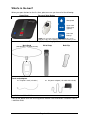
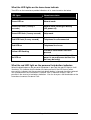
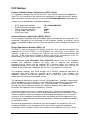
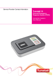
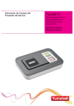
Installation and user guide
Intel-GE Care Innovations™ Link
Personal Response System
D5107152A
Connecting people to care
Contents
Intended Use..................................................................................................................2
What’s in the box?.........................................................................................................3
Care Innovations Link Personal Response System....................................................4
For your safety - installation advice.............................................................................5
Quick start guide ...........................................................................................................6
Using your Care Innovations Link personal response system ..................................8
Making a help call...................................................................................................................... 8
Cancelling a help call on the home base .................................................................................... 8
Using the Customer Care button................................................................................................ 9
Answering calls remotely using the personal help button............................................................ 9
Switching between hands-free and handset modes.................................................................... 9
Status warnings...........................................................................................................10
Telephone line monitoring........................................................................................................ 10
AC Power failure monitoring .................................................................................................... 10
What the LED lights on the home base indicate ....................................................................... 11
What the red LED light on the personal help button indicates ................................................... 11
Help and Advice ..........................................................................................................12
False alarms............................................................................................................................ 12
Troubleshooting....................................................................................................................... 12
Cleaning.................................................................................................................................. 12
Moisture .................................................................................................................................. 12
Battery information .................................................................................................................. 12
FCC Notices.................................................................................................................13
Industry Canada Warnings .........................................................................................15
Technical Details .........................................................................................................16
Intended Use
This device is intended to enable a user to request assistance by providing an additional
method of communication in the event of a potential medical emergency, specifically in a
non-clinical setting.
Page 2 of 16
What’s in the box?
When you open the box for the first time, please ensure you have all of the following:
Home Base
Personal Help Button
Waterproof
Up to 164ft
radio range
(typical)
Auto Low
Battery*
*NOTE: The personal help button will automatically send a
notification call to the monitoring center when its battery is low.
Personal Help Button Wearing Options
Neck Cord
Wrist Strap
Belt Clip
(with adjustable cord and break links)
Cords and adaptors
ⓐ
Telephone cord (10’ cable)
ⓑ
AC power adaptor (10’ cable with red tab)
Installation and User Guide
If any of the above items are missing, please contact Care Innovations Customer Care at
1-888-538-5240.
Page 3 of 16
Care Innovations Link Personal Response System
Front view
Status LED (Red)
Status LED (Green)
Speaker
Reset Button (Green)
Customer Care
Button (Blue)
Help Button (Red)
Back view
Wall Mounting Points
(screws not included)
Rechargeable
Battery
Compartment
Cover (Do Not
Open)
Programming Keypad
(For Factory Use)
Microphone
Rubber Feet x 4
End view
℡ - Telephone Jack Socket
Antenna
AUX – Accessory Jack
AC – Power Adaptor Jack (red)
Page 4 of 16
LINE – Telephone Cord Jack (green)
For your safety - installation advice
Installation with RJ31x (CA38A in Canada)
The home base unit must be able to seize the telephone line and place a call in an
emergency situation. It must be able to do this even if other equipment (telephone,
answering system, computer modem, etc.) already has the telephone line in use. To do
so, the home base must be connected to a properly installed RJ31x jack that is electrically
in series with and ahead of all other equipment attached to the same telephone line. A
separate line cord (part number XD3605044) is required to connect to an RJ31x jack.
Please contact Care Innovations Customer Care (1-888-538-5240) for further advice, if
necessary. Proper installation is depicted in the figure below.
Installation without RJ31x (CA38A in Canada)
Connect the home base unit to a telephone jack in the
home with all other telephones/extension
phones/modems/TV set top boxes (e.g. cable box) in the
home plugged directly into the home base using the jack
on the home base labeled ℡. This enables the home
base unit to disconnect extension telephones when
making a help call. A multiple telephone adaptor may be
required to connect more than one telephone (not
supplied).
Cordless phones
Ensure that your primary phone unit is connected directly to the home base as shown in
the diagram.
If you have broadband service
The home base unit includes a built in DSL filter therefore it does not need to be
connected to a separate DSL filter and can be connected to the telephone jack in the
normal manner. Please contact Care Innovations Customer Care (1-888-538-5240) for
further advice, if necessary.
Page 5 of 16
Quick start guide
Do’s
•
•
•
•
Do: Keep the home base connected to the AC power at all times.
Do: Use an RJ31x jack or connect the home base to a telephone point in the
home with all other extensions wired into the home base to ensure proper.
operation even when another telephone is in use or off hook (see page 5 for more
details).
Do: Contact Care Innovations Customer Care (1-888-538-5240) as soon as the
red LED light on your personal help button indicates a low battery (see page 11 for
more details) or if you lose your personal help button.
Do: Regularly test the home base and personal help button, this helps to
familiarize yourself with the service.
Don’ts
•
•
•
•
•
•
•
•
Don’t: Expose the home base to water or other liquids.
Don’t: Connect cables other than those supplied with the unit.
Don’t: Connect the home base to an outlet with an on/off switch.
Don’t: Place your home base next to something that makes a lot of noise, such as
next to a television, radio, washing machine or dishwasher.
Don’t: Put your home base right next to your stove or close to any other heat
source.
Don’t: Set the home base in a place where it will get damp, such as a bathroom,
or near house plants that are sprayed at any time.
Don’t: Place the home base very close to any large metal objects, such as
microwave ovens or refrigerators as large pieces of metal may stop the signals
from the personal help button from reaching the home base.
Don’t: Place your home base closer than four feet to something that may emit
electromagnetic interference, such as a cordless telephone, CD or video player, or
personal computer, as this may inhibit longer range coverage.
Step 1 - Connecting the cords & adaptors
Please follow the steps below to plug the cords correctly into the home base.
Step 1A – The telephone cord
ⓐ
is already
connected to the green jack on the home
base labeled LINE. Connect the other end of
the cord to a telephone wall jack (see page 5
for RJ31x installations).
Step 1B – Plug the telephone into the
jack on the home base labeled ℡. See
page 5 for more details.
Page 6 of 16
Step 1C – Plug the AC power adaptor
ⓑ
(with
into the red jack on the home base
labeled AC and then connect to a non-switch
controlled (always on) electrical outlet.
red tab)
Step 1D – Stand the antenna upright.
Step 2 - Testing
Press the red HELP button on the home base. You will hear a series of beeps and tones
as the home base connects with the Care Innovations Response Center. When
connected, a Response Center operator will then welcome you to the Care Innovations
family and will direct you from there.
Step 3 – Personal Help Button Range Test
Press and hold the green RESET button on the home base until you hear a beep. After
releasing the button, the home base will announce ‘programming mode’ and the green
LED will flash. While in this mode, a signal cannot be transmitted to the Care Innovations
Response Center. Test the range by pressing the personal help button from different
locations in your home. If you are within range the home base will beep and announce
‘personal trigger’.
Programming mode will automatically exit 2 minutes after the last press of the personal
help button. You can also exit programming mode at any time by pressing the green
RESET button on the home base.
NOTE: It is important to test personal help button(s) in all the areas of your home, including the bathroom,
basement and garage, as environmental conditions such as furnishings, building structure etc may affect the
range.
Step 4 – Ready to use
Once successfully tested, your Care Innovations Link personal response system is ready
for use.
Wall mounting
If you prefer that your home base be mounted on the wall, please follow these directions.
First, decide where you want to position the home base. Note that it should be within 6
feet of the AC power and main telephone line jack, as described above. Drill two holes
5.9” (149mm) apart, firmly attach screws (not supplied) and then locate the wall mounting
points on the home base with the screws.
5.9”
(149mm)
NOTE: The diagram above is for illustrative purposes only and should not be used as a measuring tool (i.e. it
is not drawn to scale).
Page 7 of 16
Using your Care Innovations Link personal response system
Making a help call
Press the black button on the personal help button or red HELP button on the home base.
The base unit will announce ‘Do not worry your alarm telephone is dialing for assistance’.
You will then hear beeps and tones while the base unit connects to the Care Innovations
Response Center. When connected a Response Center operator will speak to you and
provide the assistance you require.
Cancelling a help call on the home base
You can cancel help calls with the green RESET button on the home base. The base unit
will announce, ‘The emergency call has been cancelled’.
If you trigger a help call by pressing the red HELP button on the home base by accident,
wait 5 seconds (after the initial help button is pressed) and then press the green RESET
button. This built-in delay prevents false cancellation of a help call.
Help calls made from a personal help button can be cancelled immediately by pressing
the green RESET button on the home base.
Page 8 of 16
Using the Customer Care button
The home base has a blue Customer Care button that can be pressed to call the
Customer Care help line should you have any questions.
Answering calls remotely using the personal help button
The personal help button can be used to answer incoming telephone calls remotely by
pressing its black button while the home base or connected telephone is ringing. When
pressed, the home base will answer the call and you can speak to and hear the caller
hands free via the home base. To revert to handset mode, just pick up the handset of the
connected telephone. Replacing the handset will end the call. To end a hands free call,
press the personal help button again.
Switching between hands-free and handset modes
If you wish to change from a hands-free call to the handset, just pick up the
connected telephone handset and speak to the caller as per a normal telephone
conversation. Replacing the handset will end the call. To end a hands-free call,
press your personal help button again.
Page 9 of 16
Status warnings
Telephone line monitoring
If the telephone line is faulty or becomes disconnected or there is a problem with the
telephone service, the home base will announce ‘WARNING – the telephone line is
disconnected’ after 1 minute. This warning will be repeated every 30 seconds until the
telephone line becomes available again.
To silence the warning, re-connect the telephone line. If the telephone line is connected
and the warning continues, press the green RESET button. If the warning continues you
should contact your telephone company or supplier as the telephone line may be faulty or
out of service.
AC Power failure monitoring
If an AC power failure occurs, the home base will continue to work using its backup
battery. However, as a warning, the green LED will flash once every 4 seconds (see
section, “What the LED lights on the home base indicate”). With the light flashing, the
home base will also announce ‘WARNING – there is no electrical power’. This warning is
repeated every 5 minutes. To silence the warning, reconnect the power cord or press the
green RESET button. When the power is restored, the base unit will announce ‘The
electrical power has been restored’.
If the power failure lasts for more than 1 hour, during the next hour the unit will
automatically call the Care Innovations Response Center. A call will then be placed
periodically to the Response Center until the power is restored. The battery provides 30
hours backup.
Page 10 of 16
What the LED lights on the home base indicate
Two LEDs on the home base provide indications of its status based on the below.
LED lights
Home base status
Green LED on
Normal mode
Green LED flash (1 every 4
seconds)
Normal mode running on battery
(AC power off)
Green LED flash (1 every second)
Help mode
Red LED flash (2 every second)
Telephone line disconnected
Red LED on
Telephone line in use
Yellow LED flashing
Customer Care Button has been
pressed
No LED on
Home base unit powered down (if
power is on and connected then the
unit may be faulty)
What the red LED light on the personal help button indicates
When the black button on the personal help button is pressed, the red LED light on it will
illuminate. This indicates that the button has been pressed. If the LED flashes when
pressed, this indicates that the personal help button battery is low and should be replaced.
You should contact Care Innovations Customer Care (1-888-538-5240) as soon as
possible in the event of a low battery indication. You can also press the blue button on the
home base to contact Customer Care.
Page 11 of 16
Help and Advice
False alarms
If you accidentally activate a help call by inadvertently pressing your personal help button
or the red HELP button on the home base, please do not worry. Your Care Innovations
Response Center operator is always happy to talk with you.
Troubleshooting
If your home base does not work:
• Ensure the telephone cord is plugged into the main telephone jack – see page 6.
• Ensure that the AC power adaptor is plugged into the unit and a non-switched
(always on) electrical outlet – see page 7.
• Ensure that AC power is being supplied to the home base (the green LED light
should be on).
• If the home base has a lit or flashing LED, please see the status warning section
on page 11.
• If the above have been checked and the base unit still does not work, contact Care
Innovations Customer Care 1-888-538-5240.
Cleaning
Dust the home base with a soft cloth which can be lightly moistened with a gentle
detergent if required. Ensure that no moisture goes through the speaker grill.
The personal help button can also be cleaned in the same manner.
Moisture
Don’t position your home base where it may come into contact with water or
moisture. Personal help buttons are waterproof (to IP67 standard) up to 3 feet water
depth. They can be worn in the shower or bath however they should not be submerged
for more than 30 minutes.
Battery information
Please contact Care Innovations Customer Care (1-888-538-5240) if the battery should
need to be replaced. Do not open the battery compartment or attempt to replace the
battery.
Page 12 of 16
FCC Notices
Federal Communications Commission (FCC) notices
This equipment complies with Part 68 of the FCC rules and the requirements adopted by
the ACTA. On the exterior of the cabinet of this equipment is a label that contains, among
other information, a product identifier in the format US:G2XAL04B51004. If requested, this
number must be provided to the telephone company.
•
•
•
•
•
ACTA Registration Number:
Ringer Equivalence Number (REN):
Facility Interface Code (FIC):
Service Order Code (SOC):
USOC Jack Type:
US: G2XAL04B51004
0.4
02LS2
9.0F
RJ11C
Universal Service order Code (USOC): RJ11C
A FCC compliant telephone cord and modular plug is provided with this equipment. This
equipment is designed to be connected to the telephone network or premises wiring
using a compatible modular jack that is Part 68 compliant. See Installation Instructions for
details.
Ringer Equivalence Number (REN): 0.4
The REN is used to determine the quantity of devices that may be connected to the
telephone line. Excessive RENs on the telephone line may result in the devices not
ringing in response to an incoming call. Typically, the sum of RENs should not exceed
five (5.0). To be certain of the number of devices that may be connected to a line (as
determined by the total RENs) contact the local telephone company.
If this equipment, Care Innovations Link (51004/379), causes harm to the telephone
network, the telephone company will notify you in advance that temporary
discontinuance of service may be required. But if advance notice isn't practical, the
telephone company will notify the customer as soon as possible. Also, you will be
advised of your right to file a complaint with the FCC if you believe it is necessary.
The telephone company may make changes to its facilities, equipment, operations or
procedures that could affect the operation of the equipment. If this happens, the
telephone company will provide advance notice so you can make the necessary
modifications to maintain uninterrupted service.
This equipment (home base) contains no user serviceable parts. If trouble is experienced
with this equipment, Care Innovations Link (51004/379), for repair or warranty information
please call Care Innovations Customer Care (1-888-538-5240). If the equipment is
causing harm to the telephone network, the telephone company may request that you
disconnect the equipment until the problem is resolved.
Connection to party line service is subject to state tariffs. Contact the state public utility
commission, public service commission or corporation commission for information. If your
home has specially wired alarm equipment connected to the telephone line, ensure the
installation of this equipment (home base) does not disable your alarm equipment. If you
have questions about what will disable alarm equipment, consult your telephone company
or a qualified installer.
Alarm dialing equipment must be able to seize the telephone line and place a call in an
emergency situation. It must be able to do this even if other equipment (telephone,
answering system, computer modem, etc.) already has the telephone line in use. To do
Page 13 of 16
so, alarm dialing equipment must be connected to a properly installed RJ31X jack that is
electrically in series with and ahead of all other equipment attached to the same telephone
line. Proper installation is depicted in the following figure. If you have any questions
concerning these instructions, you should consult your telephone company or a qualified
installer about installing the RJ31X jack and alarm dialing equipment for you.
This equipment has been tested and found to comply with the limits for a Class B digital
device, pursuant to part 15 of the FCC Rules. These limits are designed to provide
reasonable protection against harmful interference in a residential installation. This
equipment generates, uses and can radiate radio frequency energy and, if not installed
and used in accordance with the instructions, may cause harmful interference to radio
communications. However, there is no guarantee that interference will not occur in a
particular installation. If this equipment does cause harmful interference to radio or
television reception, which can be determined by turning the equipment off and on, the
user is encouraged to try to correct the interference by one or more of the following
measures:
• Reorient or relocate the receiving antenna.
• Increase the separation between the equipment and receiver.
• Connect the equipment into an outlet on a circuit different from that to which the
receiver is connected.
• Consult Care Innovations Customer Care for help.
Personal Help Button (Part Number 63604/11)
FCC ID: G2X-63604 and FCC ID: G2X-63604A
This Device complies with Part 15 of the FCC Rules.
Operation is subject to the following two conditions:
(1) This device may not cause harmful interference, and
(2) This device must accept any interference received, including interference that may
cause undesired operation.
Warning: Changes or modifications to this unit not expressly approved by the party
responsible for compliance could void the user’s authority to operate the equipment.
Page 14 of 16
Industry Canada Warnings
Notice
The Industry Canada Label identifies certified equipment. This certification means that the
equipment meets telecommunications network protective, operational and safety
requirements as prescribed in the appropriate Terminal Equipment Technical
Requirements document(s). The Department does not guarantee the equipment will
operate to the user’s satisfaction. Before installing this equipment, users should ensure
that it is permissible to be connected to the facilities of the local telecommunications
company. The equipment must also be installed using an acceptable method of
connection. The customer should be aware that compliance with the above conditions
may not prevent degradation of service in some situations. Repairs to certified equipment
should be coordinated by a representative designate by the supplier. Any repairs or
alterations made by the user of this equipment, or equipment malfunctions, may give the
telecommunications company cause to request the user to disconnect the equipment.
Users should ensure for their own protection that the electrical ground connections of the
power utility, telephone lines and internal metallic water pipe system, if present, are
connected together. This precaution may be particularly important in rural areas.
Caution: Users should not attempt to make such connections themselves, but should
contact the appropriate electric inspection authority, or electrician, as appropriate.
Notice
The Ring Equivalent Number (REN) assigned to each terminal device provides an
indication of the maximum number of terminals allowed to be connected to a telephone
interface.
The termination of an interface may consist of any combination of devices subject
only to the requirement that the sum of the Ringer Equivalence Number of all the
devices does not exceed 5.
Page 15 of 16
Technical Details
Weight:
Dimensions:
AC power:
Stand-by battery:
Back-up time:
Radio frequency:
Radio range:
REN:
External connections:
2.5lb (1143g)
7.68” x 8.47” x 1.4” (195 x 215 x 36mm) (WxLxD)
110 to 120v AC power receptacle
1200mAhr capacity (continually internally recharged)
30 hours of stand-by operation with one 30 minute alarm call
(minimum expected at date of purchase and when fully
charged)
312.00MHz
390ft (120m) in free space
0.4
10ft (3m) telephone line cord with type RJ11 plug,
AC power adaptor with 10ft (3m) cable
An optional RJ31x (CA38A in Canada) line cord 10ft (3m) part
Technical Details
number XD3605044A is available – Contact Care Innovations
Customer Care 1-888-538-5240
Environmental
Temperature:
Humidity:
Operating temperature (to perform to full specification) = 0°C to
45°C (32°F to 113°F), storage = -10°C to 50°C (14°F to 122°F)
Operating relative humidity (non condensing to perform to full
specification) = 0 to 80%, storage relative humidity (non
condensing) = 0 to 93%
Standards
US:
Canadian:
FCC CFR47 part 15, FCC CFR47 part 68, ETL/UL1637,
ETL/UL1635
CETL/CSA22.2 No 205, RSS210
www.careinnovations.com/link
Manufactured for Care Innovations by Tunstall.
Copyright © 2012 Intel-GE Care Innovations LLC. All rights reserved. Care Innovations and
the Care Innovations logo are trademarks of Intel-GE Care Innovations LLC in the United
States and/or other countries. Intel and the Intel corporate logo are trademarks of Intel
Corporation in the United States and/or other countries, used under license. GE and the GE
Monogram are trademarks of General Electric Company in the United States and other
countries, used under license. *All other third-party trademarks are the property of their
respective owners.
Care Innovations Customer Care: 1-888-538-5240