1
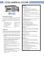
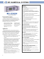
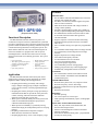
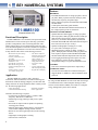
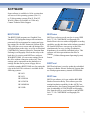
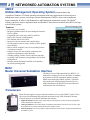
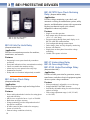
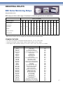
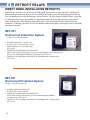
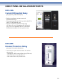
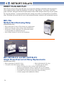
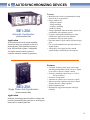
Protective Devices BASLER ELECTRIC POWER SYSTEM PROTECTION AND CONTROL PRODUCTS Basler Electric offers an extensive product line for the protection, monitoring, and control of power system generation, transmission, and distribution equipment. Whether your application requirements are for utility grade, multifunction, or discrete protective relays; communication networked integration or automation systems; or for cost-effective industrial grade relays, Basler Electric has the products you need. Protection and Control products from Basler Electric are recognized worldwide for reliability, performance, and quality of design and manufacture. With Basler Electric you can count on the service and support that you expect from an industry-leading, American-owned company with a long-term commitment to excellence. Our BE1 utility grade products meet or exceed applicable IEEE and IEC standards. For details on specifications and standards, see bulletin SDA and/or each product’s individual bulletin. For those whose needs are for high quality, reliable protection but with lower cost and performance requirements, the BE3 product line includes multifunction, numerical relays, as well as solid state, single function, DIN rail or through hole mounted relays and auto synchronizers. In addition to the products offered in this brochure, Basler Electric is a leading innovator in static excitation systems, generator voltage regulation products, and integrated engine/generator control products. See your Basler Electric Power Products Catalog. To learn more about the in-depth, broad extent of Basler Electric’s knowledge and experience in power systems protection, regulation, and control, visit us on line at www.basler.com. TABLE OF CONTENTS Section 1 BE1 Numerical Systems • BE1-851 Overcurrent Protection System .................................... • BE1-951 Overcurrent Protection System .................................... • BE1-CDS220 Current Differential Protection System ....................... • BE1-GPS100 Generator Protection System ....................................... • BE1-MMS100 Multifunction Metering System ................................... • Software ..................................................................................... 2 3 4 5 6 7 Section 2 Networked Automation Systems ...................................................................... 8 Section 3 BE1 Protective Devices (By IEEE function number) ................................... 9-15 Section 4 BE3 Protective Devices • BE3-GPR Generator Protective Relay ............................................................ 16 • BE3 Industrial Grade Relays........................................................................... 17 Section 5 Retrofit Relays Section 6 Autosynchonizing Devices .............................................................................. 21 Section 7 Accessories ................................................................................... 22 Section 8 Fax-back Forms .............................................................................. 23-24 .............................................................................. 18-20 1 BE1 NUMERICAL SYSTEMS BE1 Numerical Systems provide state of the art protection, metering, and control functions in economical, yet powerful, multifunction devices. Numerical technology enables these intelligent electronic devices to provide all functions required for a zone of protection along with wide ranges, multiple setting groups, multiple coordination curves, and low burden. In addition to this, most BE1 Numerical Systems provide options of both rack mount and retrofit friendly packages to facilitate modernizing protection and control systems in existing facilities. BESTlogic programmable logic provides the user with complete flexibility in configuring a protection and control system. Each of the functions in a BE1 Numerical Systems relay is implemented as an independent function block that is equivalent to its single function, discrete device counterpart. This programmable logic system was designed with users in mind to be immediately familiar to protection engineers and technicians. BESTlogic allows the flexibility to set up these powerful multifunction systems with the same freedom that was once enjoyed with single function, discrete devices. It is no longer necessary to compromise your standard protection and operating practices to deal with the limitations in programmability of previous multifunction devices. Typical Function Block To ease the difficulty of setting up these complex, sophisticated devices, BESTCOMS software is provided free of charge. This point and click tool makes the process of creating settings files easy and intuitive and reduces the learning curve. In addition, the ASCII command interface allows access to the complete functionality of the device without the requirement for proprietary software on your computer. Extensive reporting and alarm functions are provided to help you monitor equipment, restore systems, improve service, and reduce maintenance. Detailed sequence of events reporting (SER), fault summary reports, and oscillography recording allow detailed analysis of operations to determine the cause of relay operations. Free BESTwave COMTRADE viewer software allows you to open up to four oscillography files simultaneously to aid in event analysis. BESTCOMS System Summary Screen The three independent communications ports along with built in support for Modbus™ and DNP 3.0 provide easy access to integrating the protection, control, metering, status reporting, and monitoring functions into a substation automation system. The standard IRIG-B port provides time synchronization from a master clock. Remote control is provided by virtual control and selector switches with select before operate logic through programmable outputs. BESTwave COMTRADE Viewer 1 1 BE1 NUMERICAL SYSTEMS Features BE1-851 (Request bulletin UHM) Functional Description The BE1-851 Overcurrent Protection System is an economical, microprocessor based, multifunction system. It is fully drawout and fits cutout, drilling, and behind-panel projection dimensions for common Basler, GE, and Westinghouse relays. It provides: • Three phase, ground, and negative sequence overcurrent protection with four shot recloser • Twenty-four samples per cycle digital signal processing with selectable algorithms • Breaker failure • Three drawout case configurations • • • • Choices are fundamental, RMS, or average sensing algorithms. Control and metering functions Breaker monitoring Programmable LCD display Application The BE1-851 Overcurrent Protection System is intended for use in any nondirectional overcurrent protection application. Its unique capabilities make it ideally suited for applications: • Requiring low burden to extend the linear range of CTs. • Requiring the flexibility provided by wide setting ranges, multiple setting groups, and multiple coordination curves in one unit. • Requiring the economy and space savings provided by a multifunction, multiphase unit, while providing all of the protection, local and remote indication, metering, and control functions required on a typical circuit. • Requiring communication capability. • Requiring specific current response characteristics. • Where optional case configurations facilitate modernizing protection and control systems in existing substations. • Where the combination of digital multifunction relays and test paddles and/or drawout construction are mandated. • In applications where bus protection is provided by a high speed bus overcurrent blocking scheme instead of a dedicated bus differential circuit. • Where the capabilities of intelligent electronic devices (IEDs) are used to decrease relay and breaker maintenance costs. 2 PROTECTION • Sensing Input Type G - Three Phase and four Neutral Instantaneous Overcurrent elements with settable time delay - One Phase and two Neutral Time Overcurrent elements • Sensing Input Type H - Two each Phase, Neutral, and Negative Sequence Instantaneous Overcurrent elements with settable time delay - One each Phase, Neutral, and Negative Sequence Time Overcurrent element • All U.S. and IEC timing curves plus user-programmable curve • Responds to either Average AC, Fundamental, or Wide band RMS to 7th harmonic • Minimizes transient overreach and overtravel on overcurrent elements • Separate ground current input • Breaker Failure protection function • Two general purpose logic timers • Four protection settings groups with external or automatic (cold load pickup, load unbalance, recloser shot) selection modes CONTROL • Four shot recloser with zone sequence coordination and sequence controlled protective element blocking functions • One virtual breaker control switch and four virtual selector switches controllable from both HMI and communication ports INSTRUMENTATION • Real time phase, neutral, and negative sequence currents • 1% meter accuracy down to 10% of nominal current REPORTS • Demand reporting • Breaker operations counter and contact wear duty • 255 event sequence of events report with I/O and alarm subreports • Fault summary reports; two most recent • Fault summary records saved to nonvolatile memory • Sixteen fault records, 15 cycles long @ 24 samples/cycle • COMTRADE format SELF TEST AND ALARM FUNCTIONS • Relay Fail, major alarm, minor alarm LEDs, and fail-safe alarm output contact • Extensive internal diagnostics monitor all internal functions of the relay. Features BE1-951 (Request bulletin UHR) Functional Description The BE1-951 Overcurrent Protection System is an economical, microprocessor based, multifunction system. Using Basler Electric’s innovative half-rack, drawout design, systems can be dovetailed to form a standard 19” rack mount installation with no special mounting hardware. Using adapter plates, the S1 style fits cutout, drilling, and behind-panel projection dimensions for common Basler Electric, GE, and Westinghouse unit case relays. This protection system provides: • Three phase, ground, and negative sequence overcurrent protection with four shot recloser • Twelve samples per cycle digital signal processing with frequency compensation • Auto configuring voltage sensing circuits • • • • Breaker failure Breaker monitoring, metering, and control functions Frequency tracking and voltage restrained overcurrent Over/underfrequency and voltage Application The BE1-951 Overcurrent Protection System is intended for use in any directional or nondirectional overcurrent protection application. Its unique capabilities make it ideally suited for applications: • Requiring low burden to extend the linear range of CTs. • Requiring high accuracy across a wide frequency range such as motor, generator, and generator step-up transformer protection or in cogeneration facilities. • Requiring the flexibility provided by wide setting ranges, multiple setting groups, and multiple coordination curves in one unit. • Requiring the economy and space savings provided by a multifunction, multiphase unit, while providing all of the protection, local and remote indication, metering, and control functions required on a typical circuit. • Requiring directional control and fault locating. • Where overexcitation protection is required, such as transformer backup applications. • Requiring communications and protocol support. • Where the capabilities of digital multifunction relays with drawout construction are desirable. PROTECTION • Two each Phase, Neutral, and Negative Sequence Instantaneous Overcurrent elements with settable time delay • One Phase, Two Neutral, and One Negative Sequence Time Overcurrent elements • Neutral Overcurrent elements can be assigned to calculate residual or optional independent ground input • Phase Overcurrent element has capability of voltage restraint or control • Breaker Failure protection function • Under and overvoltage protection • Negative sequence overvoltage protection • Four protection settings groups • Fuse loss protection CONTROL • Four shot automatic recloser • One virtual breaker control switch and four virtual selector switches–controllable from both HMI and communication ports INSTRUMENTATION • Real time three phase watts, vars, and power factor • Real time frequency, current, and voltage • Real time ground current for optional independent ground input • Watt hour and Var hour REPORTS • Demand reporting • Breaker operations counter and contact wear duty • 255 event sequence of events report • Fault and oscillography records: Settable 6-16 • 240 cycles oscillography memory @ 12 samples/cycle SELF TEST AND ALARM FUNCTIONS • Relay Fail, major alarm, minor alarm LEDs, and fail-safe alarm output contact • Extensive internal diagnostics monitor all internal functions of the relay. • More than 20 additional alarm points–programmable for major or minor priority provided by virtual control and selector switches with select-before-operate logic through programmable outputs • Where bus protection is provided by a high speed overcurrent blocking scheme on the transformer bus mains instead of a dedicated bus differential circuit. • Where space constraints dictate protection systems with small size and minimal behind-panel projection for substation modernization projects. 3 1 BE1 NUMERICAL SYSTEMS Features BE1-CDS220 (Request bulletin UHP) Functional Description The BE1-CDS220 Current Differential System is an economical, microprocessor based, multifunction system. is fully drawout and fits cutout, drilling, and behind-panel projection dimensions for common Basler, GE, and Westinghouse differential relays. It provides: • Two input, three phase percentage differential with harmonic restraint • Metering functions in an integrated system with communications • Three phase, ground, and negative sequence overcurrent protection with control • • • • • It Transformer monitoring Breaker monitoring Frequency compensation Breaker failure protection Phase shift and tap compensation Application This powerful protection system provides percentage restrained differential protection along with multiple overcurrent elements. It is intended for use in any low impedance current differential protection application including transformer, generator, motor, and bus protection. Its unique capabilities make it ideally suited for applications: • Requiring low burden to extend the linear range of CTs. • Where dedicated CTs for the differential are not available. • Requiring high accuracy across a wide frequency range such as for motor, generator, and generator step-up transformer protection or in cogeneration facilities. • Requiring the flexibility provided by wide settings ranges, multiple settings groups, and multiple coordination curves in one unit. • Requiring the economy and space savings provided by a multifunction, multiphase unit that provides all the protection, along with local and remote indication, metering, and control required on typical circuits. • Requiring harmonic restraint. • Requiring communication capability and protocol support. • Where optional case configurations facilitate protection and control system modernization projects. • Where the capabilities of a digital multifunction relay with drawout construction are required. 4 PROTECTION • Percentage Restrained Current Differential with harmonic restraint • Optional Restricted Ground Fault • Three each Phase, Neutral, and Negative Sequence Instantaneous Overcurrent elements with settable time delay • Three each Phase, Neutral, Ground, and Negative Sequence Time Overcurrent elements • All U.S. and IEC timing curves plus user-programmable curve • Breaker Failure protection function • Two general purpose logic timers • Four protection settings groups with external or automatic selection modes CONTROL • One Virtual Breaker Control Switch and eight virtual selector switches–controllable from both HMI and communication ports INSTRUMENTATION • Real time phase, neutral, and negative sequence currents for each 3 phase CT input circuit • Real time ground current for optional independent ground input • Real time tap and phase compensated restraint and operate currents for each differential element • 1% meter accuracy down to 10% of nominal current REPORTS • Current Demands for phase, neutral, and negative sequence for designated CT • Optional 4000-point log of demand reading • Breaker operations counter and contact wear duty • Transformer through-fault duty statistics FAULT RECORDING • 255 event sequence of events report • Fault summary reports; two most recent Fault Summary Records saved to nonvolatile memory • 240 cycles oscillography memory @ 24 samples/ cycle • SER and Fault reporting doubled with Load Profile option is selected SELF TEST AND ALARM FUNCTIONS • Relay Fail, major alarm, minor alarm LEDs, and fail-safe alarm output contact • Extensive internal diagnostics monitor all internal functions of the relay. • More than 20 additional alarm points–programmable for major or minor priority Features BE1-GPS100 (Request bulletin UHQ) Functional Description The BE1-GPS100 Generator Protection System is an economical, microprocessor based, multifunction system that provides a comprehensive mix of protective functions to detect generator faults and abnormal operating conditions along with control and metering functions in an integrated system. Two Basler Electric half-rack units can be dovetailed together to mount in a standard 19” equipment rack with no special mounting hardware. The innovative half-rack case is fully drawout with current circuit shorting provisions. The system includes: • Fuse loss detection • Three phase, ground, and negative sequence overcurrent protection • Forward and reverse power protection • Sync check protection • • • • • Breaker failure protection Voltage protection Loss of excitation protection Frequency protection Volts per hertz protection Application The BE1-GPS100 Generator Protection System can be applied in any generator protection application. Its unique capabilities make it ideally suited for applications: • Requiring the flexibility provided by wide settings ranges, multiple settings groups, multiple coordination curves, and an extremely versatile programmable logic, in one unit. • Requiring the economy and space savings provided by a multifunction unit that can provide all of the protection, control, metering, and local and remote indication functions required in many typical units. • Where space constraints dictate protection systems with small size and minimal behind-panel projection for substation modernization projects. • Where protection redundancy is provided by having differential relaying in an independent protective relaying package. • Requiring communications and protocol support. • Where drawout construction is desirable. • Requiring high accuracy across a wide frequency range. PROTECTION • One each Phase and Neutral Instantaneous Overcurrent elements with settable time delay • One Phase, Two Neutral, and One Negative Sequence Time Overcurrent elements • Phase Overcurrent element with voltage restraint or voltage control capability • Internally calculated phase residual, 3I0, available on all relays. Optional independent ground input available. • One Instantaneous Neutral Overcurrent and two Time Overcurrent elements monitor either ground or calculated residual • Negative sequence overcurrent element with timing algorithm based on generator K factors or standard TOC curves • All U.S. and IEC timing curves plus user-programmable curve • Two each Phase Undervoltage and Overvoltage elements • Two each auxiliary Undervoltage and Overvoltage elements • Negative Sequence Overvoltage element • Four Under/Overfrequency elements • Two Forward/Reverse Power elements • Two Loss of Excitation elements • Four general purpose logic timers • Two controllable protection settings groups • Settings group selection may control tripping logic. • Automatically configurable internal VT circuits CONTROL • One virtual breaker control switch and four virtual selector switches–controllable from both HMI and communication ports INSTRUMENTATION • Real time three phase watts, vars, and power factor • Real time frequency, current, and voltage • Real time ground current for optional independent ground input • Watt hour and Var hour REPORTS • Demand reporting • 255 event sequence of events report • Fault reporting: Fault Summary reports, oscillographic records SELF TEST AND ALARM FUNCTIONS • Relay Fail, major alarm, minor alarm LEDs, and fail-safe alarm output contact • Extensive internal diagnostics monitor all internal functions of the relay. • More than 20 additional alarm points—programmable for major or minor priority 5 1 BE1 NUMERICAL SYSTEMS Features BE1-MMS100 (Request bulletin LAD) Functional Description The BE1-MMS100 is an economical, microprocessor based, multifunction revenue-accurate power metering system that provides a comprehensive mix of metering functions. This unique package allows for two Basler Electric half-rack units to be dovetailed together to mount in a standard 19" equipment rack with no special hardware. This innovative half-rack case is fully drawout with current circuit shorting provisions. • Measurement of paired voltage and current signals • Accuracy is better than 0.2% of reading • Measurement of power system harmonics to 31st • Forward and reverse power • Min and Max energy values • Optional oscillographic record of events • Optional storage of 36 days of 15 minute average data • • • • Four discrete inputs for monitoring status of input contacts from breakers, targets, switches, or monitoring pulses from utility pulse initiators Six Form A output contacts Control outputs through built-in interposing relays Keypad and LCD display Application The BE1-MMS100 is ideal for utility, industrial, commerical, and institutional use for feeder monitoring and automation, tenant sub-billing, budgetary cost allocation and outage detection. Its unique capabilities make it ideally suited for the following applications: • Utility sub-metering • Commercial/Industrial Metering • Substation Automation • Genset Applications And where the following is required: • A panel meter to read three phase V, I, Watts, VARs, frequency, Watt-hours or VAR-hours. • Monitoring of energy utilizing a utility meter's pulse contacts. • Provisions for output contacts capable of replicating metering pulse contacts. • Metering data logging and the ability to communicate with a central computer running SCADA software. • Remote or local interrogation/operation of the metering device. • High sample oscillographic recording. • Drawout case construction. 6 METERING • True RMS measurements of voltage per phase, current per phase, Watts per phase and total, VARs per phase and total, PF, frequency, and phase angle. • Energy imported, exported, and total kWh and kVARh, and total kVAh • Counts pulses from utility pulse initiators • Measures individual and total harmonic distortion on the voltage inputs up to the 31st harmonic LOGGING AND RECORDING • Optional historical data logging of voltage per phase, current per phase, Watts per phase and total, VARs per phase and total, Power Factor, frequency and pulse count every 15 minutes and imported, exported and total kWh and kVARh and total kVAh and total elapsed time since last reset for up to 36 days. • Optional oscillographic recording of 12 events, 12 cycles each at 64 samples per cycle. • Min/Max logging of voltage per phase, current per phase, Watts per phase and total, VARs per phase and total, imported, exported, and total kWh and kVARh and total kVAh and total elapsed time since last reset. • Event logging and alarming with sequence of events time stamped to ±10msec accuracy including configuration changes, set point, and min/max events. CONTROL • Four non-wetted status inputs and six output relays. COMMUNICATION • Two RS-232 and one RS-485 communications ports. • Supports DNP 3.0, Modbus, ASCII and Basler TNP protocols. By using one BE1-MMS100 on each feeder and connecting it to communicate with a central computer running SCADA software such as Basler's UMOS, the benefit of a complete energy management system can be realized. SOFTWARE Some software is available in 16-bit versions that will run on 16-bit operating systems (Win 3.1) or 32-bit operating systems (Win 95, Win NT, Win 98). Others are available in 32-bit only. Contact Technical Sales Support. BESTCOMS BESTwave The BESTCOMS programs are Graphical User Interface (GUI) programs that provide an intuitive point-and-click environment for creating and viewing settings files for BE1 Numerical Systems IEDs. They allow the user to create and edit settings files and upload them to the relay, as well as to download COMTRADE (Common Format for Transient Data Exchange) oscillography files from the relay to the hard drive for viewing with BESTwave software. With BESTCOMS, you can create settings files in the office without connection to the relay. These settings can be exported from the database to a settings file that can be put on a floppy disk or e-mailed to another BESTCOMS user for setting the relay in the field. This software is available for the following systems: BESTwave software can be used to view any IEEE Std. C37.111 COMTRADE oscillography file. Basler Electric devices with oscillographic recording capability provide their data in this industry-standard file format. BESTwave can open up to four files simultaneously for easy viewing of substation disturbances as recorded by individual relays. This software will also open transient data files in UMOS® (Utilities Management Operating System) format. BESTload BESTload software is used to update the embedded firmware in Basler Electric Numerical Systems that use Flash program memory instead of EEPROMs. BE1-851 BE1-951 BESTview BE1-GPS100 BESTview software is for use with the BE1-BPR Breaker Protection Relay. This software provides terminal emulation capability for the ASCII Command Interface, plus remote front panel HMI emulation, downloading of COMTRADE oscillography files from the relay to your hard drive, and an IEEE Std. C37.111 COMTRADE oscillography file viewer. BE1-CDS220 BE1-MMS100 BE3-GPR 7 2 NETWORKED AUTOMATION SYSTEMS UMOS Utilities Management Operating System (Request bulletin LAB) ® A graphical, Windows® NT-based operating environment with many applications in electrical power management, water systems, and sewage systems administration. UMOS® can be used to implement master stations for SCADA, Load Management, and Distribution Automation systems. The UMOS® software can also be used to implement smart and flexible PC-based remote terminal units (RTUs) for large scale SCADA systems. One Line Diagram Screen Features: • Easy to use, easy to install • Integrates communications for most Intelligent Electronic Devices (IEDs) • Compatible with a wide range of RTUs and PLCs • Built-in PLC network communications • Full-featured, mouse-driven GUI • Interactive real time monitor and control displays • On-line graphics editor to create, modify, or delete graphic screen displays • Built-in remote computer access to all operating features via modem or network • Database accepts 300 user-defined computed points (algebraic, trigonometric, and/or Boolean) • Trending: package includes 500 user-defined strip chart recordings, each increment corresponding to user-defined billing interval • Includes structured database and field device handlers for 60,000 operating points Last Trip Screen BUSI Basler Universal Substation Interface ™ The Basler Universal Substation Interface (BUSI™) is a hardened PC designed for use in a substation. It combines the functions of an RTU and human-machine interface (HMI) when running the UMOS® software. The BUSI™ will communicate with Intelligent Electronic Devices (IEDs) manufactured by Basler Electric and others and with the Basler line of transducers. Transducers Basler Electric supplies a range of network transducers for use with UMOS® systems. These devices provide distributed data acquisition and control using TNP (Transducer Network Protocol) protocol on an RS-485 multidrop data network. • Digital Transducers monitor status points and provide outputs for control of electrical equipment such as transformers and breakers. • Analog Transducers convert the output of transducers that measure electrical, water, steam, or gas flow parameters to numerical information for the UMOS® system. 8 • Pulse Transducers convert the output of pulse initiating revenue meters to numerical information for the UMOS® system. 3 BE1 PROTECTIVE DEVICES Basler Electric offers an extensive line of discrete solid-state protective devices designed to meet or exceed applicable IEEE and IEC standards. Basler BE1 relays are available in standard semi-flush drawout cases similar in appearance, connections, and mounting to electromechanical devices. Some units are available in standard 19" rack mount configurations. Most models include built-in test plugs or other provisions for testing units in the case. Advanced digital and microprocessor circuits provide precise measurement and timing accuracies. Complete specifications are found in specific product bulletins. For general standards, dimensions, and accessories, refer to Basler product bulletin SDA. Basler Electric protective relays are: • Dependable – Basler protective relays are designed to provide dependable operation in harsh substation environments. They are qualified by rigorous electrical and physical tests. The wide operating temperature range of -40°C to +70°C is indicative of the high quality level of components used in all BE1 series relays. • Secure – Using signal filtering techniques in all electronic hardware and software programs, Basler protective relays are designed and qualified in the laboratory to make correct decisions while exposed to the harsh environment common in high voltage substations. • Flexible – A variety of standard features and options includes a wide range of sensing inputs, outputs, and functional characteristics. Coupled with low burden designs, these options make it possible to tailor the products to your needs. • Adjustable – Direct reading switches, digital displays, and precision controls on the front panel provide convenient and understandable adjustments. • Available – Basler protective relays are American-made and are normally available for delivery within three to four weeks from receipt of order. APPLICATION TABLE Purpose Clear Faults Relieve Stress Relay Type Current Differential Breaker Failure Negative Sequence Excitation Temperature Voltage Restore Power Preserve System Feeders 50, 51, 50/51B, 50/51M Protected Zone Transmission Bus Transformers Generators 67, 67N 50, 51 50, 51 51/27R, 51/27C 87B 50BF 87T 87G 50BF, BPR 46N 24 27/59 Sync Multiple Shot Reclose Power 25 79M, 25/79TR 32R Frequency 81O/U Motors 51, 50/51, MPS 87G 59NC 25 79M, 25/79TR 24, 40Q, 60 MPS 27, 59, 59N 46N, 47N, MPS 40Q MPS 27, 27/59, MPS 25, 25A 32R, 32O/U 81O/U 32R, 32O/U 9 3 BE1 PROTECTIVE DEVICES BE1-25/79TR Sync-Check Reclosing Relay (Request bulletin UDW) Application Provides voltage monitoring, sync-check, and automatic reclosing for transmission systems, utility interties, and distribution systems with cogeneration. Replaces mechanical repeat cycle schemes, adaptable for almost any scheme. Features BE1-24 Volts Per Hertz Relay, BE1-25 Sync-Check Relay BE1-24 Volts Per Hertz Relay (Request bulletin UDN) Application Provides overexcitation protection for machines, transformers, and reactors. • Single or two-shot operation • Rack mount unit with drawout construction (19″ x 3.5″ x 8.4″ deep) • Program settings through front panel display or via RS-232 or RS-485 communications • Field configurable through contact inputs • Delta voltage, phase, and slip frequency monitoring • Reclose wait function • Single-phase or three-phase line and bus voltage monitoring • Variable 52b response selection Features • Integrating inverse square time delay remembers excursions • Front panel indication of time accumulated toward trip • Linear reset models the machine cooling • Alarm may be set to operate before relay trips • Instantaneous function • Pickup and reset functions independently resettable BE1-25 Sync-Check Relay BE1-27 Undervoltage Relay BE1-59 Overvoltage Relay BE1-27/59 Under/Overvoltage Relay (Request bulletin UBF) Application Provides reliable protection for generators, motors, transformers, and other electrical equipment against adverse system voltage conditions. (Request bulletin UBP) Features Application • Pickup continuously adjustable over a wide range • Independent INST and TIME elements • Individually adjustable timing for each time-delayed under/overvoltage • Wide voltage adjustment range (1-40V, 55-160V, or 110-320V) Checks for proper phase angle and voltage before closing breaker. Features • Direct reading thumbwheel switches for setting phase angle and time delay • May be set to respond as fast as 1 cycle of 50/60Hz • Better than one degree accuracy • Voltage monitoring provides independent check of bus and line conditions • SCADA control of phase window for emergency closure of critical ties • External voltage conditions selectivity 10 BE1-32O/U Directional Over/ Underpower Relay and BE1-32R Directional Overpower Relay BE1-46N Negative Sequence Overcurrent Relay (Request bulletin UBU) Application Application Protects machines against excessive heating damage due to prolonged current unbalance. The BE1-32O/U Directional Over/Underpower relay and the BE1-32R Directional Overpower relay are solid state devices that protect machines and systems against underpower and overpower, and reverse power flow conditions. Features • Senses actual power flow (EI cos θ) • Operating range down to a power factor of 0.1 • Sensitivity not affected by negative sequence currents • Input configurations available for single and multiple phases • Sensing ranges cover 0.5W to 6000W secondary • Instantaneous, definite, or inverse time characteristics • Supplied in S1 or M1 case, depending on options (Request bulletin UDJ) Features • • • • Replicates heating characteristics of machines Pickup may be set as low as 1% negative sequence Unaffected by ±5 Hz frequency changes Output contacts for alarm, trip, and initiating other devices • External panel meter to display negative sequence current level BE1-47N Negative Sequence Voltage Relay (Request bulletin UDK) Application Provides protection against reverse phase sequence, unbalance, or open phase. BE1-40Q Loss of Excitation Relay (Request bulletin UBW) Application Protects 50 or 60 Hz synchronous generators against the consequences of loss of field conditions. Features • • • • Pickup may be set as low as 2% negative sequence Unaffected by ±5 Hz frequency changes Inverse, definite, and instantaneous timing options Independent overvoltage and undervoltage elements Features • Measures Var flow to sense loss of excitation • Trip characteristics are defined on complex plane for ease of application • Definite time characteristics BE1-50 Instantaneous Overcurrent Relay (Request bulletin UBC) Application Provides high speed protection for phase and/or ground faults. Features • Setting ranges cover 0.25 to 32 amps • Single-phase, three-phase, two-phase with neutral, or three-phase with neutral configurations 11 3 BE1 PROTECTIVE DEVICES • Field-selectable curves including ABB/CO, British Standard, and GE IAC (200 Series only), and wide pickup range simplifies specifying and stocking • A1 or S1 case • Testable in the case BE1-50/51M Time Overcurrent Relay (Request bulletin UHE) Application BE1-50/51M Time Overcurrent Relay, BE1-50/51B Time Overcurrent Relay, BE1-67 Phase Directional Time Overcurrent Relay, BE1-51 Time Overcurrent Relay Single-phase self-powered, microprocessor based time overcurrent relay. Provides protection in applications requiring time delayed coordination for phase or ground overcurrent conditions. Features BE1-50BF Breaker Failure Relay (Request bulletin UBT) Application Provides protection and security for the power system against failure of the monitored breaker. Features • • • • • • Cycle control timer sets failure detection window Less than 1 millisecond fault detector reset time Two independently timed initiation/control inputs Field adjustable logic Wide operating frequency range Three breaker fail outputs plus one instantaneous retrip • • • • • • • • • • Self-powered from 50/60Hz systems Independent instantaneous element 1 or 5 Amp CTs Replicates decaying reset of electromechanical relays Drawout construction Direct reading controls for settings even when the relay is powered down Field-selectable curves including ABB/CO, British Standard, and GE IAC (200 Series only) Standard magnetically latched targets Compact size C1 case (6.88"W x 4.00"H x 7.00"D) Continuous automatic calibration Available in four-unit vertical rack BE1-51 Time Overcurrent Relay (Request bulletin UDA) BE1-50/51B Time Overcurrent Relay Application (Request bulletin UHD) Versatile AC/DC powered microprocessor relay provides overcurrent protection for phase and ground applications. Application Self-powered, microprocessor, single-phase time overcurrent relay provides overcurrent protection for phase and ground applications. Features • • • • • Self-powered from 50/60Hz systems Independent instantaneous element 1 or 5 Amp CTs Replicates decaying reset of electromechanical relays Drawout construction Direct reading controls for settings even when the relay is powered down 12 Features • Single-phase, three-phase, two-phase with neutral, or three-phase with neutral configurations • Zero, one, or two instantaneous outputs • Available with voltage control or voltage restraint • Sixteen field selectable time-current curves • High dropout ratio BE1-59N Ground Fault Overvoltage Relay BE1-60 Voltage Balance Relay (Request bulletin UBS) (Request bulletin UBG) Application Provides sensitive ground fault protection for ungrounded or high resistance grounded systems, including stator ground fault protection. Features • • • • Overvoltage element tuned to reject harmonics Pickup down to 0.1 volts Withstands full rated voltage continuously Third harmonic undervoltage element for 100% stator protection • Instantaneous, definite, or inverse time characteristics • Four sensitivity ranges for under and overvoltage Application Detects voltage imbalances on relay and control circuits. Features • Wide range adjustment (5% to 50%) • Six input sensing types to match various system configurations • Maximum trip time of 100 milliseconds BE1-67 Phase Directional Time Overcurrent Relay (Request bulletin UDQ) BE1-59NC Capacitor Neutral Overvoltage Relay Application (Request bulletin UHF) Microprocessor based phase directional time overcurrent relay used to protect circuits where power can flow in either direction. Application Features: Provides alarming for minor capacitor bank imbalance and tripping before the imbalance threatens cascading capacitor failures. • • • • • • Features • Helps avoid cascading capacitor failures • Sensing circuit rejects harmonics and noise to achieve higher sensitivity to 50/60 Hz neutral voltage • Includes an early warning alarm output on minor unbalances such as a blown fuse • Can be set to trip when voltage across any capacitor exceeds 110% of nominal Single- or three-phase configurations Sensitive down to one volt on polarizing input Twelve field selectable time-current curves Quadrature (90 degree) voltage polarization Directional or non-directional instantaneous elements Limited region provides additional security BE1-67N Ground Directional Overcurrent Relay (Request bulletin UDR) Application Microprocessor directional overcurrent relay senses direction and magnitude of ground faults. Features • Twelve field selectable time-current curves • Directional and non-directional instantaneous elements • Directional element polarized by zero sequence current, zero sequence voltage, or phasor sum of zero sequence quantities 13 3 BE1 PROTECTIVE DEVICES BE1-87B Bus Differential Relay, BE1-BPR Breaker Protection Relay, BE1-81O/U Digital Frequency Relay BE1-79M Multiple Shot Reclosing Relay BE1-81O/U Digital Frequency Relay (Request bulletin UDL) (Request bulletin UBR) Application Application Provides automatic reclosing of tripped circuit breakers in power transmission and distribution systems. Protects the system during over or underfrequency conditions. Features • • • • • • • Instantaneous and maximum of three time delayed reclosing attempts • Direct reading thumbwheel switches for setting reclose and reset delays • Reclosing sequence may be selected via external contacts • Nonvolatile memory circuits retain operating data • Individual alarm contacts for lockout, reclose fail, and relay failure • Instantaneous trip enable output for control of tripping relays • Output for blocking load tap changer (LTC) • Reclose wait and special reclose functions • Pilot reclose Features: Direct frequency trip settings Accuracy of ±0.003 Hz Pickup adjustable in increments of 0.01 Hz 40 to 70 Hz operating range Up to 4 independent over or underfrequency set points Undervoltage inhibit NEW BE1-87B Bus Differential Relay (Request bulletin UHC) Application Provides economical high impedance differential protection in single- or three-phase packages. Features • • • • 14 High Impedance Bus Differential Power supply fail alarm Alarm to alert for excessive steady state imbalance Unique shorted CT circuit diagnostic test function BE1-87G Variable Percentage Differential Relay BE1-BPR Breaker Protection Relay (Request bulletin UBK) Application Application Intended for use in any three-pole tripping, breaker failure protection application. Provides high speed solid-state variable percentage differential protection for generators, motors, and shunt reactors. Features • • • • Single-phase and three-phase units Sensitivity is adjustable from 0.1 to 1.6 Amps. Variable percentage restraint characteristic Current balancing reactors help improve CT performance on external faults. • High speed (20 milliseconds) operation BE1-87T Transformer Differential Relay (Request bulletin UHA) Application (Request bulletin UHG) Features • Three-phase and neutral current inputs monitor currents on power system and in protected circuit breaker. • 12 sample per cycle digital signal processing measures RMS value of current flowing in circuit breaker. • Seven programmable inputs and five programmable outputs with BESTlogic provides complete system configuration flexibility. • Unique timer margin diagnostics to monitor critical margins after every operation • Available in horizontal 19″ rack mount and vertical panel mount case • Onboard breaker diagnostics Used for primary protection against internal faults in power transformers. Features • Single-phase sensing with up to five single-phase inputs • Three-phase sensing with up to three sets of inputs • Provides precision ratio matching in 0.1 Amp steps • Second and fifth harmonic restraint for overexcitation and inrush security • Phase shift compensation eliminates need for delta or auxiliary CTs. • Power supply status output • Push-to-energize output switches • Displays percent Iop MPS Motor Protection Systems (Request bulletin UPB for MPS200/210, UPC for MPS100) Application Intended for use in any three-phase, induction motor protection application. Provides protection from faults and abnormal operating conditions. Features • MPS100 provides complete overcurrent and thermal overload protection for three-phase induction motors. • The MPS200 adds three-phase voltage inputs to provide voltage and power protection and metering functions. • The MPS210 adds integrated motor control functions. • All MPS relays include an integrated LCD display for setup and local indication. • The MPS100 is available in a vertical fixed case. The MPS2xx relays are available in either vertical or horizontal fixed cases or a Basler M1 drawout case with test paddle for current and voltage inputs. 15 4 BE3 PROTECTIVE DEVICES Features BE3-GPR (Request bulletin UEG) Functional Description The BE3-GPR Generator Protective Relay offers multiple protective features in a single economical package. Its microprocessor-based design provides high accuracy, reliability, and repeatability through exact set point adjustment and precise generator system protection. • Low sensing burdens mean that the BE3-GPR does not require dedicated VTs and CTs. • Optional protection features allow for customizing the BE3-GPR to meet individual system requirements. • One set of three phase current and voltage sensing inputs provides all common protective functions except generator differential, 87G. The voltage sensing circuits may be configured internally for three-phase three wire, three-phase four wire, or single-phase circuits. A fourth voltage input for bus voltage is optional. • Each protective function is brought out to its isolated Form C output contact. • The BE3-GPR is extremely easy to set up from the front panel or with an IBM compatible PC. • The LCD display makes calibration quick, easy, and accurate without the need to bench test the relay to verify settings. • Mounting configuration choices include semi-flush and behind the panel. Application The BE3-GPR Generator Protective Relay meets utility grade specifications and is suitable for any generator application, as well as many utility and cogeneration facility intertie applications. It offers a limited number of precision settings to make setup fast, easy, and accurate. 16 PROTECTION Stand-alone Generator Version: • Under/Overvoltage: 27/59 • Under/Overfrequency: 81O/U • Underfrequency: 81U • Neutral Ground Fault: 51N or Three Phase Time Overcurrent with Voltage Restraint: 51/27R Paralleled Generator Version: • Adds Reverse Power (32R) Optional Protective Functions: • Sync Check with Dead Bus (25) • Loss of Excitation (40) • Phase Balance (47) PROGRAMMABILITY • Front panel LCD display and pushbuttons • Basler BESTCOMS software • Output contacts can be programmed to energize or de-energize to trip • Trip, Reset, and Time delays for each function can be programmed INPUTS • Available reset input allows relay to automatically reset when fault goes away or to maintain output until an input is received. • A disable input contact disables the relay to avoid nuisance tripping during generator build-up. WATCHDOG TIMER • Monitors microprocessor • Energizes output relay if problem occurs COMMUNICATIONS • Send or receive ASCII characters in serial data format • Communicate with PC running terminal emulation setup program • Basler BESTCOMS software is available for enhanced HMI communications and metering of generator parameters. INDUSTRIAL RELAYS BE3 Series Monitoring Relays (Request bulletin ULX) BE3 relays provide a wide range of functions for industrial applications as listed below. DEVICE NUMBER* APPLICATION 25 27 Auto Transfer X Distribution X Generators X Motors X X Process Control 32 37 47 X X X 47N 49R 49T 51 59 74S 74T 81O 81U X X X X X X X X X X X X X X X X X X X X X X X X X X X X X X X X X X X X X Transformers X X X X X X X X * IEEE Device Numbers form an integral part of the Basler Electric Model Number. COMMON FEATURES • UL listed, CSA certified, CE compliant. Mounting: DIN rail 1.38”x.29” (35mx7.5mm) • Self powered. Nominal voltage: 120Vac, 240Vac, 380Vac, 480Vac; Current: 5 Amps. • Cases comply to IEC 529 and UL 94VO; 2.17”or 3.94” x 2.87” x 4.41” (55 or 100 x 73 x 112mm) MODEL NUMBER BE3-25 BE3-27 BE3-27/59 BE3-27T BE3-27T/59T BE3-32 BE3-37 BE3-37/51 BE3-47 BE3-47N BE3-47N/27 BE3-49R BE3-49R BE3-49TH BE3-49TL BE3-51 BE3-59 BE3-59T BE3-74SD BE3-74SH BE3-74SL BE3-74TD BE3-74TH BE3-74TL BE3-74VD BE3-74VH BE3-74VL BE3-81O BE3-81O/U BE3-81U BE3-81OT BE3-81UT BE3-81OT/UT TYPE Sync-Check Undervoltage Over/Undervoltage Undervoltage with Time Delay Over/Undervoltage with Time Delay Reverse Power Undercurrent Under/Overcurrent Phase Sequence Phase Balance Phase Balance with Undervoltage Temperature (3 RTD) Temperature (6 RTD) Thermocouple Overtemperature Thermocouple Undertemperature Overcurrent Overvoltage Overvoltage with Time Delay Millivolt Under/Overvoltage Millivolt Overvoltage Millivolt Undervoltage Milliamp Under/Overcurrent Milliamp Overcurrent Milliamp Undercurrent DC Under/Overvoltage DC Overvoltage DC Undervoltage Overfrequency Over/Underfrequency Underfrequency Overfrequency with Time Delay Underfrequency with Time Delay Over/Underfrequency with Time Delay PRODUCT BULLETIN ULA ULB ULB ULC ULC ULD ULE ULE ULF ULG ULG ULH ULI ULJ ULJ ULE ULB ULC ULN ULN ULN ULO ULO ULO ULP ULP ULP ULL ULL ULL ULM ULM ULM 17 5 RETROFIT RELAYS DIRECT PANEL INSTALLATION RETROFITS Basler Electric provides you with the best of both worlds: State-of-the-art, fully numerical, multifunction protection that can help you improve service, reliability, and reduce costs; with packaging options that can save you installation costs for modernizing existing facilities. The fully numerical Basler Electric relays that are featured on these pages are available in configurations that will fit into the panel space and cutout of many of the obsolete relays that they functionally replace. All include fully drawout construction with automatic CT shorting provisions. Several also include traditional test plugs, reducing the need for installing external test switches. BE1-851 Overcurrent Protection System (see page 2 for product description) • Available in half-rack, S1 and F1 cases • S1 fits GE IAC overcurrent relay, F1 case fits Westinghouse CO overcurrent relay (FT11 case). • The BE1-851 S1 with adapter plate 9108551021 fits GE ACR or NLR reclosing relay (S2 case) and Westinghouse RCL reclosing relay (FT21 case) or Westinghouse MMCO overcurrent relay (FT22 case). • The BE1-851 S1 with adapter 9108551022 fits Westinghouse RC reclosing relay (FT32 case). BE1-951 Overcurrent Protection System (see page 3 for product description) • Available in half-rack and S1 cases • S1 fits GE IAC overcurrent relay. • The BE1-951 S1 with adapter plate 9108551021 fits GE ACR or NLR reclosing relay (S2 case) and Westinghouse MMCO overcurrent relay (FT22 case). • The BE1-951 S1 with adapter 9108551022 fits Westinghouse RC reclosing relay (FT32 case). 18 DIRECT PANEL INSTALLATION RETROFITS BE1-CDS Current Differential Relay (see page 4 for product description) • Replaces transformer, generator, motor and bus differential relays • Direct mounting holes for GE-M1 and -M2, ABB-FT-31 and FT-32 and Basler M1 cases • Retrofits GE-BDD and STD differential relay (GE M1 or M2 case), Westinghouse HU differential relay (FT31 case) and Basler BE1-87T Transformer Differential relay (Basler M1 case) panel cut-outs BE1-BPR Breaker Protection Relay (see page 15 for product description) • Vertical unit to replace obsolete breaker fail and fault detector relays - Westinghouse SBF-1 breaker failure relay (FT32 case) - CHC fault detector relay (GE M2 case) - SBC breaker failure relay (GE M2 case) 19 5 RETROFIT RELAYS DIRECT PLUG AND PLAY Basler Electric also provides relays that allow you to enjoy the advantages of modern solid state protective relays without having to modify the installation. We offer true "plug and play" convenience with utility grade, solid state, microprocessor-based replacements for three of the most prevalent relays on your system. By "true plug and play", we mean replacement in the existing cases with no rewiring and no case modifications. This means you can be back in service with minimal downtime, minimal work, and minimal expense. BE1-79A Multiple Shot Reclosing Relay (Request bulletin UHN) • Direct replacement for most ACR reclosing relay configurations • Installs in existing case with no wiring or panel modifications • Functionality of ACR is duplicated via cradle mount switches or front panel RS-232 communications port. • Also available in Basler S1 case for new installations BE1-50/51B-214 and BE1-50/51B-219 Single Phase Overcurrent Relay Replacements (Request bulletin UHDS) • Direct replacement for most IAC relays • Direct replacement for CO relays • -214 replaces more than 100 IAC models • -219 replaces 40 CO models • Installs in existing case with no wiring or panel modifications • Self powered and includes memory to replicate the reset of E/M disks • Self-calibrating eliminates need for recalibration, reducing maintenance. • 10 selectable curves and wide pickup ranges reduce inventory. • All units equipped with instantaneous element 20 6 AUTOSYNCHRONIZING DEVICES Features BE1-25A Automatic Synchronizer (Request bulletin UIM) Application A microprocessor based system including features to bring any generator on line in a minimum time, from small diesel units to large, difficult hydro plants. Configurable for simple manual control systems or complete automatic control of generators. • Multiple breaker with six programmable closing times for up to six generators • Plug-in modules for: - Voltage acceptance - Voltage matching - Frequency matching - Dead bus closing • Voltage adjustment function has three options for coordination with regulating system. • Frequency adjustment function may be either continuous or pulsed to provide optimum performance of the governor system. • Real time adaptive speed control with smart target pulse • For use with standard motor operated controls or digital adjuster • Anticipatory close signal provides smooth synchronizing with minimum system impact. Features BE3-25A Single Phase Auto-Synchronizer • Generator frequency, phase angle, and voltage matching through either bipolar corrective signals or raise/lower corrective output contacts • Frequency matching capture range is ±3 Hz of the bus frequency. • Dead-bus closing option • Automatic or remote reset of corrective signals • Bipolar correction signal provides direct control of Basler Electric voltage regulator. • Built-in operational test • Mechanically rugged and compact with high reliability (Request bulletin UMP) Application Monitors oncoming generator and bus voltages and permits synchronizing the generator to an energized station bus or another generator. 21 7 ACCESSORIES Mounting Accessories Test Accessories • A rack mounting plate is available to vertically mount four BE1-50/51M units in a standard 19” rack. Order P/N 9252012001. • Adapter plate to mount single S1 case in GE 52 or Westinghouse FT-21 cutout. Order P/N 9108551021. • Adapter plate to mount single S1 case in Westinghouse FT-32 cutout. Order P/N 9108551022. • Adapter bracket to mount single H1 case in 19” rack. Order P/N 9289924100. • Escutcheon plate to panel mount two dovetailed H1 relays. Order P/N 9289900016. • Escutcheon plate to panel mount one H1 relay. Order P/N 9289900017. • Escutcheon plate to panel mount one horizontal BE1-BPR relay. Order P/N 9272013101. • Test plug for providing quick, easy method of testing drawout case type relays without removing them from the case. Order P/N 10095. • Test fixture that provides input power and signals for a full functional test. Includes switches to manually activate sensing inputs and indications for trip and close outputs. Order P/N 9231542100. • Test case for S1 relays. Order P/N 9180400104. • Test case for M1 relays. Order P/N 9180400105. • S1 test case for BE1-851 and BE1-951 relays. Order P/N 9180400110. • BE1-79M test box to facilitate bench testing. Order P/N 9170114100. • BE1-25/79TR test box to facilitate bench testing. Order P/N 9231542100. • BE1-BPR test box to facilitage bench testing. Order P/N 9272010100. • BE1-851, BE1-951, BE1-GPS100 test box to facilitate bench testing. Order P/N 9289922100. • H1 test case with 1 CT terminal block and 12-position bottom terminal block (BE1-851). Order P/N 9180400106. • H1 test case with 1 CT terminal block and 18-position bottom terminal block (BE1-GPS100, BE1-MMS100, BE1-951). Order P/N 9180400108. • F1 test case with 1 CT terminal block (BE1-851). Order P/N 9180400107. • MX test case with 2 CT terminal blocks (BE1-CDS220). Order P/N 9180400109. ESD201/ESD202 (Request bulletin UJO) Application Energy storage devices can be used when a station battery source is not available for circuit breaker tripping. Features • ESD201 converts ac input into dc and stores sufficient energy to trip the circuit breaker for up to 72 hours after ac is removed. • ESD202 converts ac input and stores sufficient energy to trip the circuit breaker for at least 12 seconds. • Compact and economical. 22 8 FAX SHEET Please fax this page to +1 618.654.2351. Please print clearly and provide all information requested below. Name: ____________________________________________________ Date: ______________________ Title: _________________________________________________________________________________ Firm: _________________________________________________________________________________ Street: ________________________________________________________________________________ City: ______________________________ State/Province: _______________ Zip/Postal Code: ________ Phone: __________________________ FAX: _____________________ E-mail: _____________________ o Yes Do you plan to buy or specify protective equipment: Action: o Immediately o 1-6 months o No o 6-12 months Industry Classification: o o o o o o Electric Utility Consulting Engineer Government Agency Switchgear Assembler Gen-set Manufacturer Gen-set Assembler o o o o o o Generator Manufacturer Contractor Industrial Firm Independent Power Producer Repair and Service Shop Other _____________________ Please send information on the following: SECTION(s) o o o o o o o o 1 2 3 4 5 6 7 SPECIFIC PRODUCT(s) Numerical Networked Automation BE1 Protective BE3 Protective Retrofits Autosynchronizers Accessories Other Route 143, Box 269 • Highland, IL 62249-0269 USA Telephone: +1 618.654.2341 • FAX: +1 618.654.2351 • http://www.basler.com From United States and Canada call Basler Info Center +1 800.562.5656 23 8 FAX SHEET Please fax this page to +1 618.654.2351. Please print clearly and provide all information requested below. Name: ____________________________________________________ Date: ______________________ Title: _________________________________________________________________________________ Firm: _________________________________________________________________________________ Street: ________________________________________________________________________________ City: ______________________________ State/Province: _______________ Zip/Postal Code: ________ Phone: __________________________ FAX: _____________________ E-mail: _____________________ o Yes Do you plan to buy or specify protective equipment: Action: o Immediately o 1-6 months o No o 6-12 months Industry Classification: o o o o o o Electric Utility Consulting Engineer Government Agency Switchgear Assembler Gen-set Manufacturer Gen-set Assembler o o o o o o Generator Manufacturer Contractor Industrial Firm Independent Power Producer Repair and Service Shop Other _____________________ Please send information on the following: SECTION(s) o o o o o o o o 24 1 2 3 4 5 6 7 SPECIFIC PRODUCT(s) Numerical Networked Automation BE1 Protective BE3 Protective Retrofits Autosynchronizers Accessories Other Route 143, Box 269 • Highland, IL 62249-0269 USA Telephone: +1 618.654.2341 • FAX: +1 618.654.2351 • http://www.basler.com From United States and Canada call Basler Info Center +1 800.562.5656 HOW TO REACH US WEB SITE: Visit us at www.basler.com (Includes list of local sales representatives) E-MAIL: [email protected] FAX: +1 618.654.2351 TELEPHONE: +1 618.654.2341 Power Systems Group Customer Service MAIL: Basler Electric Company Power Systems Group Box 269, Route 143 Highland, IL USA 62249 European Headquarters: Basler Electric International, P.A.E. Les Pins, 67319 Wasselonne Cedex FRANCE Telephone: +33 3.88.87.1010, Fax: +33 3.88.87.0808 Route 143, Box 269 • Highland, IL 62249 U.S.A. Telephone: +1 618.654.2341 • Fax: +1 618.654.2351 • http://www.basler.com PD0BRO Printed in U.S.A.


![Roberts Gorden Combat UHD[X][S][R] 75 Service manual](http://vs1.manualzilla.com/store/data/007345245_1-6c2b7b8586e1a29d3cd560010fb01c7d-150x150.png)