1
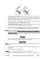
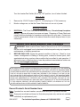
5 IN 1 PORTABLE POWER PACK
Model 96157
OperatiON Instructions
Visit our website at: http://www.harborfreight.com
Read this material before using this product.
Failure to do so can result in serious injury.
Save this manual.
Copyright© 2007 by Harbor Freight Tools®. All rights reserved. No portion of this manual or any artwork
contained herein may be reproduced in any shape or form without the express written consent of Harbor
Freight Tools. Diagrams within this manual may not be drawn proportionally. Due to continuing improvements, actual product may differ slightly from the product described herein. Tools required for assembly
and service may not be included.
For technical questions or replacement parts, please call 1-800-444-3353.
Revised Manual 09l
Specifications
Case
Thermoplastic housing with mold-over armored rubber
Battery
12V/18Ah Lead-acid Battery
Cables
36” Long 6AWG gauge coated copper wire
Power Output
Two 115VAC outlets
Outlet Socket
Two 12 VDC
Input Port
AC-DC Charging Ports with Adapters
Weight
19.6 Pounds
Other Features
600 Amp Crank, 1000 Amp Surge Jumpstart
Push-button Battery Test
5 L.E.D. Work Light,
DC Volts Gauge, 1.75” Dia.
12V 260 PSI Compressor w/ 24” L. Hose & Gauge
3 Air Nozzle Adapters
Push-in Fuse for Cooling Fan
Low Voltage Alarm if battery voltage <10-10.2V
Low Voltage Shutdown at 8.2-8.4V
Save This Manual
You will need this manual for the safety warnings and precautions, assembly, operating, inspection, maintenance and cleaning procedures, parts list and assembly diagram.
Keep your invoice with this manual. Write the invoice number on the inside of the front
cover. Write the product’s serial number in the back of the manual near the assembly diagram, or write month and year of purchase if product has no number. Keep this manual
and invoice in a safe and dry place for future reference.
GENERAL SAFETY RULES
WARNING!
READ AND UNDERSTAND ALL INSTRUCTIONS
Failure to follow all instructions listed below may result in
electric shock, fire, and/or serious injury.
SAVE THESE INSTRUCTIONS
Work Area
1.
Keep your work area clean and well lit. Cluttered benches and dark areas invite
accidents.
2.
Do not operate the Power Pack in explosive atmospheres, such as in the presence of flammable liquids, gases, or dust. The Power Pack can create sparks
which may ignite the dust or fumes.
REV 08a; 09e
SKU 96157
For technical questions, please call 1-800-444-3353.
Page 2
3.
Keep bystanders and children away while operating the Power Pack. Distractions can cause you to lose control. Provide barriers or shields as needed.
4.
Avoid body contact with grounded surfaces such as pipes, radiators, ranges,
and refrigerators. There is an increased risk of electric shock if your body is
grounded.
5.
Do not expose the Power Pack to rain or wet conditions. Water entering the
Power Pack will increase the risk of electric shock.
6.
Stay alert. Watch what you are doing, and use common sense when operating
the Power Pack. Do not use the Power Pack while tired or under the influence of
drugs, alcohol, or medication. A moment of inattention while operating power tools
may result in serious personal injury.
7.
Use safety equipment. Always wear ANSI-approved eye protection. Dust mask,
nonskid safety shoes, hard hat, or hearing protection must be used for appropriate
conditions.
8.
Do not force the Power Pack. Use the correct tool for your application. The correct tool will do the job better and safer at the rate for which it is designed. Do not
force the tool and do not use the tool for a purpose for which it is not intended.
9.
Do not use the Power Pack if the Power Switch does not turn it on or off. Any
tool that cannot be controlled with the Power Switch is dangerous and must be
replaced.
10.
Disconnect the Power Pack from the power source before making any adjustments, changing accessories, or storing the tool. Such preventive safety
measures reduce the risk of starting the tool accidentally.
11.
Store idle tools out of reach of children and other untrained persons. Tools
are dangerous in the hands of untrained users.
12.
Maintain labels and nameplates on the tool. These carry important information.
If unreadable or missing, contact Harbor Freight Tools for a replacement.
13.
People with pacemakers should consult their physician(s) before use. Electromagnetic fields in close proximity to heart pacemaker could cause pacemaker
interference or pacemaker failure.
14.
WARNING: This product contains lead, which is a chemical known to the State
of California to cause cancer and birth defects or other reproductive harm.
(California Health & Safety Code § 25249.5, et seq.)
15.
Avoid contact with Battery Acid. If splashed, immediately wash effected area
with clean water. Continue washing area until medical help arrives.
16.
Connect cables to proper polarities. Connect black cable to negative body ground
and red cable to positive battery terminal.
REV 09e
SKU 96157
For technical questions, please call 1-800-444-3353.
Page 3
17.
Do not allow the Black and Red clamps to touch. Injury to the operator or property damage can occur if this happens.
18.
For emergency use only. Do not use this system in the place of a vehicle battery.
Only use to jump start the vehicle.
19.
Lead acid batteries generate additional hydrogen gas when charging. Hydrogen gas is explosive. Only use the Jump-start System in a well-ventilated area. Do
not allow smoking in the area.
20.
Never exceed the maximum charging time of the Power Pack. Maximum AC
charge time is 48 hours. Maximum DC charge time is 24 hours.
Service
1.
Tool service must be performed only by qualified repair personnel. Service or maintenance performed by unqualified personnel could result in a risk of injury.
2.
When servicing a tool, use only identical replacement parts. Follow instructions
in the “Inspection, Maintenance, And Cleaning” section of this manual. Use of unauthorized parts or failure to follow maintenance instructions may create a risk of
electric shock or injury.
Unpacking
When unpacking, check to make sure that the item is intact and undamaged. If any
parts are missing or broken, please call Harbor Freight Tools at the number shown on the
cover of this manual as soon as possible.
Operation Instructions
Note: For additional information regarding the parts listed in the following pages, refer to
the Assembly Diagram near the end of this manual.
Charging the Power Pack
Note: Before initial use, it is necessary to completely charge the Power Pack. Initial
charge time when using an AC outlet is 48 hours. Initial charge time when using a
DC outlet is 24 hours. Always charge on concrete or tile, not on surfaces that are
flammable or surfaces that could get heat damaged.
1.
Press and hold the Battery Status Button (23) on the front of the unit to check the
battery power level: 13 - 15 Volts is ready for use, 12 Volts needs to be charged,
less than 12 Volts should be charged immediately.
2.
Turn the Jump-start Power Switch (18) on the back of the unit to the “OFF” position.
REV 09e
SKU 96157
For technical questions, please call 1-800-444-3353.
Page 4
DC Adapter (31)
AC Adapter (30)
3.
To charge from an AC power source. After the initial charge, use only the AC
Adapter (30) provided with the unit. Plug first into any standard 120V socket, and
then into Power Pack. Allow up to 34 hours for the unit to fully charge. The pack
must not be continually charged for over 34 hours at a time.
4.
When the Power Pack is fully charged, unplug from the 120V socket and unit. Do
not exceed the maximum AC charge time of 34 hours.
5.
To charge from a DC power source, plug the DC Adapter (31) into any 12V outlet
and then into the AC/DC charging jack on the front of the unit.
6.
After the initial charge, fully charging the Power Pack by a DC connection will take
about 12 hours. Do not exceed the maximum DC charge time of 12 hours.
Note: The Charging Indicator light will illuminate when the Power Pack is charging with
both AC or DC input. The Charging Indicator light will not turn off when the
charging is complete. The Voltmeter (10) must be checked periodically when
charging and the Power Pack must be unplugged when the unit is fully charged.
DO NOT OVERCHARGE.
Work Light
To turn on the L.E.D. Work Light (13), push the Work Light Switch (25) to the “ON”
position. Turn Work Light Switch to “OFF” position when done.
Jump-starting
Note: Read the vehicle owner’s manual prior to using the Power Pack to jump-start the
vehicle.
1.
Turn off the ignition switch of the vehicle and all accessories (lights, radio etc.) of
the vehicle off.
2.
Turn all switches on the Power Pack off.
Caution: Do not touch Positive and Negative Battery Clamps together.
3.
Connect the red Positive Battery Clamp (27) to the vehicle’s positive battery terminal.
REV 08a
SKU 96157
For technical questions, please call 1-800-444-3353.
Page 5
4.
Connect the black Negative Battery Clamp (28) to a non-moving metal part
of the vehicle. DO NOT CONNECT TO THE NEGATIVE TERMINAL OF THE
BATTERY.
5.
The Connection Indicator Light (17) will glow green if a correct connection has
been made. If the Connection Indicator Light turns red, review, and change the
connections.
6.
When the correct connection has been made, turn the Jump-start Power Switch
(18) to the “ON” position.
7.
Start vehicle. If vehicle does not start, wait an additional 3 minutes before trying
again. Failure to wait 3 minutes may damage the Power Pack.
8.
After vehicle is started, remove the black Negative Battery Clamp first, and then
the red Positive Battery Clamp.
Air Compressor
1.
Open Compartment Door (5) on the back of the unit and pull out the air hose.
2.
Check proper inflation level for the object that is being inflated.
3.
Lift lever on air nozzle and connect the appropriate adapter (stored in the same
area as the air hose and nozzle) for your intended use. Move lever down to lock
adapter in place.
4.
Turn Air Compressor Switch (24) to “ON” position. (“0”=OFF, “1”=ON)
5.
Watch the Compressor Gauge (15) on the front of the unit to avoid over-inflation.
6.
When the object reaches the proper inflation level, turn off Air Compressor and
disconnect hose. Do not overinflate any object.
AC Inverter
1.
Before connecting the Inverter, make sure the Inverter/Fan Switch (26) is in the
“OFF” position. (Push on “0” portion of the switch)
2.
Plug the appliance into an AC Socket (29) of the Power Pack.
3.
Press the Inverter/Fan Switch to the “ON” position. If the inverter is working correctly,
the light underneath the Inverter/Fan Switch will illuminate green.
4.
Turn on the appliance, if the light remains on, the system is functioning normally. If
the light turns off, immediately turn off the appliance and the inverter and see the
“Troubleshooting Guide” section of the manual.
5.
Monitor voltage use, so that the Power Pack does not drain completely.
SKU 96157
For technical questions, please call 1-800-444-3353.
Page 6
Fan
Turn the Inverter/Fan Switch (26) to the “ON” position, turn off when finished.
12 Volt DC
1.
Remove the 12V DC Socket Cover (11, 12) and plug in a 12 Volt accessory.
2.
Monitor voltage use, so that the Power Pack does not run out of power.
Battery Disposal
1.
DISPOSAL: The Power Pack uses a lead-acid battery. Do not attempt to replace
battery. Remove all screws from case and open. Disposing of Power Pack must
comply with the standards for hazardous waste disposal in your area. Contact your
local city government office for the nearest hazardous waste disposal area in your
community.
INSPECTION, MAINTENANCE, AND CLEANING
1.
WARNING! Make sure the Power Switch of the tool is in its “OFF” position and
that the tool is unplugged from its electrical outlet before performing any inspection,
maintenance, or cleaning procedures.
2.
BEFORE EACH USE, inspect the general condition of the tool. Check for loose
screws, misalignment or binding of moving parts, cracked or broken parts, damaged electrical wiring, and any other condition that may affect its safe operation. If
abnormal noise or vibration occurs, have the problem corrected before further use.
Do not use damaged equipment.
PLEASE READ THE FOLLOWING CAREFULLY
The manufacturer and/or distributor has provided the parts list and assembly diagram in this manual as a reference tool only. Neither the manufacturer
or distributor makes any representation or warranty of any kind to the buyer
that he or she is qualified to make any repairs to the product, or that he or
she is qualified to replace any parts of the product. In fact, the manufacturer
and/or distributor expressly states that all repairs and parts replacements
should be undertaken by certified and licensed technicians, and not by the
buyer. The buyer assumes all risk and liability arising out of his or her repairs
to the original product or replacement parts thereto, or arising out of his
or her installation of replacement parts thereto.
Record Product’s Serial Number Here:
Note: If product has no serial number, record month and year of purchase instead.
Note: Some parts are listed and shown for illustration purposes only, and are not available
individually as replacement parts.
REV 08j
SKU 96157
For technical questions, please call 1-800-444-3353.
Page 7
Troubleshooting
SKU 96157
For technical questions, please call 1-800-444-3353.
Page 8
LIMITED 90 DAY WARRANTY
Harbor Freight Tools Co. makes every effort to assure that its products meet high quality and durability standards, and warrants to the original purchaser that this product is free from defects in materials and
workmanship for the period of 90 days from the date of purchase. This warranty does not apply to damage
due directly or indirectly, to misuse, abuse, negligence or accidents, repairs or alterations outside our facilities, criminal activity, improper installation, normal wear and tear, or to lack of maintenance. We shall in no
event be liable for death, injuries to persons or property, or for incidental, contingent, special or consequential
damages arising from the use of our product. Some states do not allow the exclusion or limitation of incidental
or consequential damages, so the above limitation of exclusion may not apply to you. This warranty is
expressly in lieu of all other warranties, express or implied, including the warranties of merchantability and fitness.
To take advantage of this warranty, the product or part must be returned to us with transportation
charges prepaid. Proof of purchase date and an explanation of the complaint must accompany the merchandise. If our inspection verifies the defect, we will either repair or replace the product at our election or we may
elect to refund the purchase price if we cannot readily and quickly provide you with a replacement. We will
return repaired products at our expense, but if we determine there is no defect, or that the defect resulted
from causes not within the scope of our warranty, then you must bear the cost of returning the product.
This warranty gives you specific legal rights and you may also have other rights which vary from
state to state.
3491 Mission Oaks Blvd. • PO Box 6009 • Camarillo, CA 93011 • (800) 444-3353
Parts list
Part
Description
Part
Description
1
Main Body (Front)
18
Jump-start Power Switch
2
Main Body (Back)
19
Positive Cable
3
Positive Clamp Holder
20
Negative Cable
4
Negative Clamp Holder
21
Fan/Inverter
5
Compartment Door
22
Battery
6
Back Panel
23
Battery Status Button
7
Front Panel
24
Air Compressor Switch
8
Transparent Panel
25
Work Light Switch
9
12V 40A Fuse
26
Inverter/Fan Switch
10
Voltmeter
27
Positive Battery Clamp
11
DC Socket Cover
28
Negative Battery Clamp
12
DC Socket
29
AC Socket
13
L.E.D. Work Light
30
AC Adapter
14
Air Compressor
31
DC Charger
15
Compressor Gauge
32
3 Air Nozzle Adapters (not shown)
16
PCB - Inverter
17
Connection Indicator
NOTE: Some parts are listed and shown for illustration purposes only, and are not available individually as replacement parts.
REV 08a
SKU 96157
For technical questions, please call 1-800-444-3353.
Page 9
ASSEMBLY DIAGRAM
REV 08a
SKU 96157
For technical questions, please call 1-800-444-3353.
Page 10