1
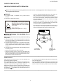
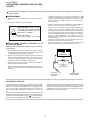
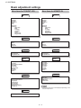
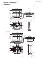
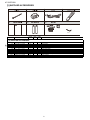
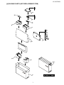
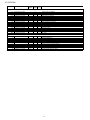
TopPage LC-32/37D43U SERVICE MANUAL No. SX6Y9LC37D43U LCD COLOR TELEVISION MODELS LC-32D43U LC-37D43U In the interests of user-safety (Required by safety regulations in some countries) the set should be restored to its original condition and only parts identical to those specified be used. OUTLINE This model is based on the LC-32D42U/LC-37D42U and partially modified. For the contents not covered in this Service Manual, accordingly, please refer to the 37D42U (S06X9LC32D42U) Service Manual. LC-32D42U/LC- CONTENTS DIFFERENCES FROM BASE MODEL LIST OF CHANGED PARTS ............................. i CHAPTER 2. OPERATION MANUAL [1] OPERATION MANUAL ...................................2-1 SAFETY PRECAUTION IMPORTANT SERVICE SAFETY PRECAUTION ......................................................... ii PRECAUTIONS A PRENDRE LORS DE LA REPARATION .............................................iii PRECAUTIONS FOR USING LEADFREE SOLDER ............................................... iv CHAPTER 3. DIMENSIONS [1] DIMENSIONS .................................................3-1 Parts Guide CHAPTER 1. SPECIFICATIONS [1] SPECIFICATIONS......................................... 1-1 Parts marked with " " are important for maintaining the safety of the set. Be sure to replace these parts with specified ones for maintaining the safety and performance of the set. This document has been published to be used for after sales service only. The contents are subject to change without notice. LC-32/37D43U LC-32D43U LCD EService Market LC-32D43U/LC-37D43U TV Manual FROM BASE MODEL DIFFERENCES LIST OF CHANGED PARTS Ref. No. Description LC-32D42U/LC-37D42U PRINTED WIRING BOARD ASSEMBLIES MAIN Unit DUNTKD862FM04 R/C, LED Unit DUNTKD909FM02 KEY Unit DUNTKD910FM02 AV TERMINAL Unit DUNTKD999FM04 POWER Unit RDENCA198WJQZ LC-32D43U/LC-37D43U DUNTKD862FM04 DUNTKD909FM02 DUNTKD910FM02 DUNTKD999FM04 RDENCA198WJQZ Note No Changes No Changes No Changes No Changes No Changes Refer to the PARTS GUIDE for CABINET PARTS, SUPPLIED ACCESORIES,PACKING PARTS and SERVICE JIGS. i LC-32/37D43U LC-32D43U SAFETY PRECAUTION Service Manual IMPORTANT SERVICE SAFETY PRECAUTION Service work should be performed only by qualified service technicians who are thoroughly familiar with all safety checks and the servicing guidelines which follow: WARNING 1. For continued safety, no modification of any circuit should be attempted. 2. Disconnect AC power before servicing. V Use an AC voltmeter having with 5000 ohm per volt, or higher, sensitivity or measure the AC voltage drop across the resistor. • Connect the resistor connection to all exposed metal parts having a return to the chassis (antenna, metal cabinet, screw heads, knobs and control shafts, escutcheon, etc.) and measure the AC voltage drop across the resistor. All checks must be repeated with the AC cord plug connection reversed. (If necessary, a nonpolarized adaptor plug must be used only for the purpose of completing these checks.) CAUTION: FOR CONTINUED PROTECTION AGAINST A RISK OF FIRE REPLACE ONLY WITH SAME TYPE FUSE. A • Any reading of 0.75 Vrms (this corresponds to 0.5 mA rms AC.) or more is excessive and indicates a potential shock hazard which must be corrected before returning the monitor to the owner. F701 (125V 8A), F4701, F5701 (250V 3A ~ 115 C) O DVM AC SCALE BEFORE RETURNING THE RECEIVER (Fire & Shock Hazard) 1.5k ohm 10W Before returning the receiver to the user, perform the following safety checks: 3. Inspect all lead dress to make certain that leads are not pinched, and check that hardware is not lodged between the chassis and other metal parts in the receiver. 0.15 µF TEST PROBE 4. Inspect all protective devices such as non-metallic control knobs, insulation materials, cabinet backs, adjustment and compartment covers or shields, isolation resistor-capacitor networks, mechanical insulators, etc. 5. To be sure that no shock hazard exists, check for leakage current in the following manner. • Plug the AC cord directly into a 120 volt AC outlet. • Using two clip leads, connect a 1.5k ohm, 10 watt resistor paralleled by a 0.15µF capacitor in series with all exposed metal cabinet parts and a known earth ground, such as electrical conduit or electrical ground connected to an earth ground. TO EXPOSED METAL PARTS CONNECT TO KNOWN EARTH GROUND /////////////////////////////////////////////////////////////////////////////////////////////////////////////////////////////////////////////////////////////////////////////////////////////////////////////////////////////////////////// SAFETY NOTICE Many electrical and mechanical parts in LCD color television have special safety-related characteristics. For continued protection, replacement parts must be identical to those used in the original circuit. These characteristics are often not evident from visual inspection, nor can protection afforded by them be necessarily increased by using replacement components rated for higher voltage, wattage, etc. The use of a substitute replacement parts which do not have the same safety characteristics as the factory recommended replacement parts shown in this service manual, may create shock, fire or other hazards. Replacement parts which have these special safety characteristics are identified in this manual; electrical components having such features are identified by " " and shaded areas in the Replacement Parts List and Schematic Diagrams. /////////////////////////////////////////////////////////////////////////////////////////////////////////////////////////////////////////////////////////////////////////////////////////////////////////////////////////////////////////// ii LC-32/37D43U PRECAUTIONS A PRENDRE LORS DE LA REPARATION Ne peut effectuer la réparation qu' un technicien spécialisé qui s'est parfaitement accoutumé à toute vérification de sécurité et aux conseils suivants. AVERTISSEMENT • A l'aide de deux fils à pinces, brancher une résistance de 1.5 k 10 watts en parallèle avec un condensateur de 0.15µF en série avec toutes les pièces métalliques exposées du coffret et une terre connue comme une conduite électrique ou une prise de terre branchée à la terre. 1. N'entreprendre aucune modification de tout circuit. C'est dangereux. 2. Débrancher le récepteur avant toute réparation. • Utiliser un voltmètre CA d'une sensibilité d'au moins 5000 /V pour mesurer la chute de tension en travers de la résistance. PRECAUTION: POUR LA PROTECTION CONTINUE CONTRE LES RISQUES D'INCENDIE, REMPLACER LE FUSIBLE A V • Toucher avec la sonde d'essai les pièces métalliques exposées qui présentent une voie de retour au châssis (antenne, coffret métallique, tête des vis, arbres de commande et des boutons, écusson, etc.) et mesurer la chute de tension CA en-travers de la résistance. Toutes les vérifications doivent être refaites après avoir inversé la fiche du cordon d'alimentation. (Si nécessaire, une prise d'adpatation non polarisée peut être utilisée dans le but de terminer ces vérifications.) La tension de pointe mesurèe ne doit pas dépasser 0.75V (correspondante au courant CA de pointe de 0.5mA). Dans le cas contraire, il y a une possibilité de choc électrique qui doit être supprimée avant de rendre le récepteur au client. F701 (125V 8A), F4701, F5701 (250V 3A ~ 115 C) O VERIFICATIONS CONTRE L'INCEN-DIE ET LE CHOC ELECTRIQUE Avant de rendre le récepteur à l'utilisateur, effectuer les vérifications suivantes. 3. Inspecter tous les faisceaux de câbles pour s'assurer que les fils ne soient pas pincés ou qu'un outil ne soit pas placé entre le châssis et les autres pièces métalliques du récepteur. DVM ECHELLE CA 4. Inspecter tous les dispositifs de protection comme les boutons de commande non-métalliques, les isolants, le dos du coffret, les couvercles ou blindages de réglage et de compartiment, les réseaux de résistancecapacité, les isolateurs mécaniques, etc. 1.5k ohm 10W 5. S'assurer qu'il n'y ait pas de danger d'électrocution en vérifiant la fuite de courant, de la facon suivante: 0.15 µF SONDE D'ESSAI • Brancher le cordon d'alimentation directem-ent à une prise de courant de 120V. (Ne pas utiliser de transformateur d'isolation pour cet essai). AUX PIECES METALLIQUES EXPOSEES BRANCHER A UNE TERRE CONNUE ///////////////////////////////////////////////////////////////////////////////////////////////////////////////////////////////////////////////////////////////////////////////////////////////////////////////////////////////////////////// AVIS POUR LA SECURITE Pour assurer la protection, ces pièces doivent être identiques à celles utilisées dans le circuit d'origine. L'utilisation de pièces qui n'ont pas les mêmes caractéristiques que les pièces recommandées par l'usine, indiquées dans ce manuel, peut provoquer des électrocutions, incendies, radiations X ou autres accidents. De nombreuses pièces, électriques et mécaniques, dans les téléviseur ACL présentent des caractéristiques spéciales relatives à la sécurité, qui ne sont souvent pas évidentes à vue. Le degré de protection ne peut pas être nécessairement augmentée en utilisant des pièces de remplacement étalonnées pour haute tension, puissance, etc. Les pièces de remplacement qui présentent ces caractéristiques sont identifiées dans ce manuel; les pièces électriques qui présentent ces particularités sont identifiées par la marque " " et hachurées dans la liste des pièces de remplacement et les diagrammes schématiques. ///////////////////////////////////////////////////////////////////////////////////////////////////////////////////////////////////////////////////////////////////////////////////////////////////////////////////////////////////////////// iii LC-32/37D43U PRECAUTIONS FOR USING LEAD-FREE SOLDER Employing lead-free solder • “PWBs” of this model employs lead-free solder. The LF symbol indicates lead-free solder, and is attached on the PWBs and service manuals. The alphabetical character following LF shows the type of lead-free solder. Example: Indicates lead-free solder of tin, silver and copper. Indicates lead-free solder of tin, silver and copper. Using lead-free wire solder • When fixing the PWB soldered with the lead-free solder, apply lead-free wire solder. Repairing with conventional lead wire solder may cause damage or accident due to cracks. As the melting point of lead-free solder (Sn-Ag-Cu) is higher than the lead wire solder by 40 °C, we recommend you to use a dedicated soldering bit, if you are not familiar with how to obtain lead-free wire solder or soldering bit, contact our service station or service branch in your area. Soldering • As the melting point of lead-free solder (Sn-Ag-Cu) is about 220 °C which is higher than the conventional lead solder by 40 °C, and as it has poor solder wettability, you may be apt to keep the soldering bit in contact with the PWB for extended period of time. However, Since the land may be peeled off or the maximum heat-resistance temperature of parts may be exceeded, remove the bit from the PWB as soon as you confirm the steady soldering condition. Lead-free solder contains more tin, and the end of the soldering bit may be easily corroded. Make sure to turn on and off the power of the bit as required. If a different type of solder stays on the tip of the soldering bit, it is alloyed with lead-free solder. Clean the bit after every use of it. When the tip of the soldering bit is blackened during use, file it with steel wool or fine sandpaper. • Be careful when replacing parts with polarity indication on the PWB silk. Lead-free wire solder for servicing PARTS CODE ZHNDAi123250E ZHNDAi126500E ZHNDAi12801KE PRICE RANK BL BK BM PART DELIVERY J J J DESCRIPTION φ0.3mm 250g (1roll) φ0.6mm 500g (1roll) φ1.0mm 1kg (1roll) iv LC-32/37D43U CHAPTER 1. SPECIFICATIONS LC-32D43U Service Manual [1] SPECIFICATIONS Item Model: LC-37D43U Model: LC-32D43U LCD panel 32 Advanced Super View & BLACK TFT 37 Advanced Super View & BLACK TFT LCD LCD Number of dots 3,147,264 dots (1366 TV Function TV-standard (CCIR) American TV Standard ATSC/NTSC System Receiving Channel VHF/UHF VHF 2-13ch, UHF 14-69ch CATV 1-135ch (non-scrambled channel only) 768 3 dots) Digital Terrestrial 2-69ch Broadcast (8VSB) Digital cable*1 1-135ch (non-scrambled channel only) (64/256 QAM) Audio multiplex Audio out Terminals BTSC System 10W Rear 2 INPUT 1 AV in, COMPONENT in INPUT 2 S-VIDEO in, AV in INPUT 3 Audio in, COMPONENT in INPUT 4 HDMI in with HDCP INPUT 5 Audio in, HDMI in with HDCP INPUT 6 15 pin mini D-sub, Audio in (Ø 3.5 mm jack) ANTENNA 75 Unbalance, F Type 1 for Analog (VHF/UHF/CATV) and Digital (AIR/CABLE) DIGITAL AUDIO OUTPUT Optical Digital audio output OUTPUT Audio out OSD language English/French/Spanish Power Requirement AC 120 V, 60 Hz Power Consumption Weight Dimension*2 (W H D) 1 (PCM/Dolby Digital) 175 W (0.95 W Standby with AC 120V) 185 W (0.95 W Standby with AC 120V) w/o stand 36.4 lbs./16.5 kg 43.0 lbs./19.5 kg with stand 43.0 lbs./19.5 kg 50.7 lbs./23.0 kg w/o stand 11 31 / 32 59 20 / 64 3 / 64 inch 3561/ 64 2337/ 64 353/ 64 inch with stand 3111/ 32 2313/ 64 937/ 64 inch 3561/ 64 2527/ 32 1135/ 64 inch Operating temperature 32°F to 53 104°F (0°C to *1 40°C) Emergency alert messages via Cable are unreceivable. The dimensional drawings are shown on the inside back cover. • As part of policy of continuous improvement, SHARP reserves the right to make design and speci cation changes for product improvement without prior notice. The performance specication gures indicated are nominal values of production units. There may be some deviations from these values in individual units. *2 1–1 LC-32/37D43U LCD EService Market LC-32D43U/LC-37D43U TV Manual CHAPTER 2. OPERATION MANUAL LC-32D43U [1] OPERATION MANUAL Part names TV (Front) Remote control sensor OPC indicator* OPC sensor* SLEEP indicator POWER indicator NOTE *OPC: Optical Picture Control TV (Rear) Channel buttons (CH / ) HDMI terminal (INPUT 4) Volume buttons (VOL - / + ) HDMI terminal (INPUT 5) INPUT button POWER button PC IN terminals (INPUT 6) Antenna/Cable in AUDIO terminals (INPUT 5) DIGITAL AUDIO OUTPUT terminal INPUT 3 terminals INPUT 2 terminals INPUT 1 terminals AUDIO OUTPUT terminals AC INPUT terminal 2–1 LC-32/37D43U Part names 1 Remote control unit 1 2 3 14 4 2 3 15 4 16 5 6 17 7 18 8 19 9 20 10 21 22 11 23 24 25 26 12 13 27 5 6 7 8 9 TV POWER: Switch the TV power on or enters standby mode. DISPLAY: Display the channel information. SOURCE POWER: Turns the power of the external equipment on and off. External equipment operational buttons: Operate the external equipment. 0 – 9: Set the channel. • (DOT): INPUT: Select a TV input source. (TV, INPUT 1, INPUT 2, INPUT 3, INPUT 4, INPUT 5, INPUT 6) VOL / : Set the volume. SURROUND: Select Surround settings. 10 FREEZE: Set the still image. Press again to return to normal screen. 11 EXIT: Turn off the menu screen. 12 SLEEP: Set the sleep timer. 13 AUDIO: Selects the MTS/SAP or the audio mode during multi-channel audio broadcasts. 14 FUNCTION: Switches the remote control for TV, CBL/SAT, VCR, DVD and AUDIO operation. Indicator lights up for the current mode. * To enter the code registration mode, you need to press FUNCTION and DISPLAY at the same time. 15 LIGHT : When pressed all buttons on the remote control unit will light. The lighting will turn off if no operations are performed within about 5 seconds. This button is used for performing operations in lowlight situations. 16 VIEW MODE: Select the screen size. 17 ENT: Jumps to a channel after selecting with the 0–9 buttons. 18 FLASHBACK: Return to the previous channel or external input mode. 19 CH : Select the channel. 20 MUTE: Mute the sound. 21 MENU: Display the menu screen. 22 ENTER: Select a desired item on the screen. 23 RETURN: Return to the previous menu screen. 24 FAVORITE CH A, B, C, D: Select 4 preset favorite channels in 4 different categories. While watching, you can toggle the selected channels by pressing A, B, C and D. 25 FAVORITE: Register favorite channel. 26 CC: Display captions from a closed-caption source. 27 AV MODE: Select an audio or video setting. (When the input source is TV, INPUT 1, 2 or 3: STANDARD, MOVIE, GAME, USER, DYNAMIC (Fixed), DYNAMIC. When the input source is INPUT 4, 5 or 6: STANDARD, MOVIE, GAME, PC, USER, DYNAMIC (Fixed), DYNAMIC) NOTE • When using the remote control unit, point it at the TV. 2–2 LC-32/37D43U QUICK REFERENCE Attaching the stand Before attaching (or detaching) the stand, unplug the AC cord from the AC INPUT terminal. Before performing work spread cushioning over the base area to lay the TV on. This will prevent it from being damaged. CAUTION Attach the stand in the correct direction. Be sure to follow the instructions. Incorrect installation of the stand may result in the TV falling over. 1 Confirm that there are 9 screws (all the same size) supplied with the TV. 3 Insert the stand into the openings on the bottom of the TV. Insert and tighten the 4 screws into the 4 holes on the rear of the TV. Hex key 2 Set the post for the stand unit onto the box. Attach the base to the post. Insert and tighten the 5 screws into the 5 holes on the bottom of the base. Screw Soft cushion Hex key Screw NOTE To detach the stand, perform the steps in reverse order. 2–3 LC-32/37D43U Basic adjustment settings Menu items for TV/INPUT 1/2/3 Menu items for HDMI/PC-IN Picture Picture OPC Backlight Contrast Brightness Color Tint Sharpness Advanced Color Temp. Black I/P Setting Film Mode 3D-Y/C Monochrome Range of OPC OPC Backlight Contrast Brightness Color Tint Sharpness Advanced Color Temp. Black I/P Setting Film Mode Monochrome Range of OPC Audio Audio Treble Bass Balance Surround Treble Bass Balance Surround Power Control Power Control No Signal Off No Operation Off No Signal Off No Operation Off Setup Setup EZ Setup CH Setup Antenna Setup-DIGITAL Input Skip Input Label Parental CTRL Position Language Reset Input Skip Input Signal Auto Sync. Input Label Fine Sync. Position Language Reset Option Option Audio Only Digital Noise Reduction HDMI Setup Output Select Audio Only Digital Noise Reduction Input Select Output Select Color System Caption Setup Program Title Display Favorite CH NOTE Some menu items may not be displayed depending on the selected input source. Digital Setup Audio Setup 2–4 LC-32/37D43U LCD EService Market LC-32D43U/LC-37D43U TV Manual CHAPTER 3. DIMENSIONS LC-32D43U [1] DIMENSIONS Unit: inch/(mm) LC-32D43U 3111/ 32 (796) 131/ 2 (343) 1535/ 64 (394.6) 2059/ 64 (531) 29/ 32 (58) 2313/ 64 (589) 279/ 16 (700.0) 1945/ 64 (500) 1945/ 64 (500) 39/ 32 (83) 353/ 64 (97) 77/ 8 (200) 323/ 64 (85) 77/ 8 (200) 937/ 64 (243) LC-37D43U 3561/ 64 (913) 2135/ 64 (547) 2135/ 64 (547) 1 2 / 4 (57) 27 14 / 32 (377) 1817/ 64 (463.8) 23 / 64 (599) 37 2527/ 32 (656) 3225/ 64 (822.6) 45/ 8 (117) 353/ 64 (97) 77/ 8 (200) 23 3 / 64 (85) 77/ 8 (200) 1135/ 64 (293) 3–1 LC-32/37D43U -MEMO- 3–2 LC-32/37D43U PartsGuide PARTS GUIDE No.SX6Y9LC37D43U LCD COLOR TELEVISION MODELS LC-32D43U LC-37D43U CONTENTS [1] CABINET AND MECHANICAL PARTS (LC-32D43U) [4] PACKING PARTS (NOT REPLACEMENT ITEM) [2] CABINET AND MECHANICAL PARTS (LC-37D43U) [5] SERVICE JIGS (USE FOR SERVICING) [3] SUPPLIED ACCESSORIES Parts marked with " " are important for maintaining the safety of the set. Be sure to replace these parts with specified ones for maintaining the safety and performance of the set. This document has been published to be used for after sales service only. The contents are subject to change without notice. LC-32/37D43U [1] CABINET AND MECHANICAL PARTS (LC-32D43U) 36 47 41 36 3 41 3-1 3-2 36 48 36 47 41 26 41 4 49 39 50-2 14 50-1 32 1-7 1 36 31 50 14 1-11 1-1 1-6 1-8 1-5 33 1-7 29 1-6 1-11 1-8 39 1-8 1-3 1-12 1-8 1-10 1-11 1-13 1-8 1-8 40 35 1-2 1-8 42 11 1-9 2 1-4 2-1 35 2-5 34 2-3 34 36 2-2 24 2-4 46 34 46 36 25 21 36 34 36 27 18 5-2 17 19 7 30 5-1 20 23 34 7-2 13 7-4 36 36 7-2 5 37 7-3 36 15 9 40 16 22 36 7-1 6-1 12 38 6-2 8 10 44 6 36 45 28 43 45 2 LC-32/37D43U NO. PARTS CODE PRICE NEW PART RANK MARK DELIVERY DESCRIPTION [1] CABINET AND MECHANICAL PARTS (LC-32D43U) 1 1-1 1-2 1-3 1-4 1-5 1-6 1-7 1-8 1-9 1-10 1-11 1-12 1-13 2 2-1 2-2 2-3 2-4 2-5 3 3-1 3-2 4 5 5-1 5-2 6 6-1 6-2 7 7-1 7-2 7-3 7-4 8 9 10 11 12 13 14 15 16 17 18 19 20 21 22 23 24 25 26 27 28 29 30 31 32 33 34 35 36 37 38 39 40 41 42 43 44 45 46 47 48 49 50 50-1 50-2 CCABAB612WJ03 Not Available Not Available Not Available Not Available HPNLSA100WJSA Not Available Not Available Not Available TLABZA635WJZZ TLABZB392WJSA XJPSN30P08XS0 HDECSA014WJSA Not Available CCABBA950WJ01 Not Available Not Available LHLDWA057WJKZ PSPAHB078WJZZ LHLDWA055WJKZ CCOVAB929WJ01 Not Available Not Available R1LK315T3LF15 CSLDMB061WJ01 Not Available LHLDWA102WJKZ CANGKA902WJ01 Not Available Not Available CCHSMA346WJ01 Not Available LHLDWA102WJKZ LHLDWA120WJKZ Not Available GCOVAA678WJKA GCOVAB931WJKA HINDPB715WJSA HINDPC239WJSA LANGKA913WJM1 LANGKA914WJFW LX-HZA003WJFN LX-NZ3047GEZZ NSFTZ0134CEFW PCLICA004WJKZ PRDARA414WJFW PSPAZA635WJKZ PSPAZA917WJKZ PSPAZB030WJKZ QCNCWA496WJZZ QCNW-E249WJPZ QCNW-E257WJQZ QCNW-E258WJQZ QCNW-E266WJQZ QCNW-E278WJQZ QCNW-E703WJPZ QCNW-F250WJQZ QCNW-F300WJQZ QCNW-F316WJQZ RSP-ZA215WJZZ RSP-ZA216WJZZ XBBS740P06000 XBBS930P06000 XBPS730P06WS0 XBPS830P06000 XEBS930P08000 XEBS930P10000 XEBS940P16000 XEBSN40P10000 Not Available CDAI-A332WJ01 Not Available LX-BZA176WJF9 LANGTA414WJM1 LANGHA052WJFW LANGHA051WJFW LANGKA929WJFW CANGKA930WJ01 Not Available LHLDWA120WJKZ BT AY AD AF AA AQ BH AE AS AC AS EC AW AB AN AZ AB AB AF AQ AC AM BC AL AC AA AD AC AK AC AH AB AK AH AH AG AF AH AX AL AL AG AY AY AA AA AA AA AA AA AB AB AF AP AG AG AK AL AB N N N N N N N N N N N N N S N S N N N N N S N N N N N N N N N N N N N N N N N N N X X X X J X X J X X J X J X X J J X X X X X X J J J J X J J J X J J J J J X X X X X X J J J J J J J J X X X X X X X J Front Cabinet Ass'y Front Cabinet LED Cover Front Cover Badge, SHARP SP-Net Spacer, x2 Spacer, x2 Spacer, x7 POP Label POP Label Screw (for Front Cover), x3 Shine trim Spacer Rear Cabinet Ass'y Rear Cabinet Terminal Label Wire Holder Spacer, x6 Wire Holder Top Cover Ass'y Top Cover Operation Button 32" WIDE LCD Panel Module Unit MAIN Shield Ass'y MAIN Shield Wire Holder, x3 Jack Angle Ass'y Jack Angle Jack Indicator Tray Chassis Ass'y Tray Chassis Wire Holder, x3 Wire Holder Barrier Sheet SD Card Cover Stand Area Cover Terminal Label Model Label Stand Fix Angle Stand Assist Angle Screw (for SP-BOX), x4 Nut Shaft, x2 Rivet, x3 Heat Sink Cool Sheet Cool Sheet Spacer Connector (F-RCA) Connecting Cord (ANT IN) Connecting Cord (PE) Connecting Cord (PD) Connecting Cord (KM) Connecting Cord (SH) Connecting Cord (LV) Connecting Cord (RA) Connecting Cord (LA-LA-LB) Connecting Cord (SP) Speaker (L) Speaker (R) Screw (for ANG), x6 Screw (for CAB-B), x5 Screw (for PWB,ANG), x41 Screw (for HDMI), x2 Screw (forJack) Screw (for LED), x2 (for SOUSA), x2 Screw (for CAB-B), x10 Screw (for PANEL), x4 No. Label Stand Base Ass'y Stand Support Screw (forStand), x9 Center Angle, x2 Rug Angle Top, x2 Center Angle Top Rug Angle Bottom L Rug Angle Bottom R Ass'y Rug Angle Bottom R Wire Holder 3 LC-32/37D43U [2] CABINET AND MECHANICAL PARTS (LC-37D43U) 36 47 41 36 3 3-1 41 3-2 1 26 36 48 36 49 47 41 41 4 50-2 39 14 1-12 32 50-1 31 1-7 36 14 1-1 1-11 1-6 1-8 39 1-6 1-11 1-8 33 29 1-7 1-5 1-3 50 1-8 1-11 1-8 40 1-13 1-10 1-8 1-8 35 1-2 42 11 1-8 1-9 1-4 2-5 34 36 2-3 34 24 2-2 2-4 46 25 49 36 34 27 17 18 5-2 19 7 30 34 36 36 21 35 2-1 2 20 23 7-2 5-1 7-4 34 7-2 36 13 37 7-3 36 15 36 5 16 9 22 36 7-1 6-1 8 6 40 38 6-2 10 12 36 44 28 45 43 45 4 LC-32/37D43U NO. PARTS CODE PRICE NEW PART RANK MARK DELIVERY DESCRIPTION [2] CABINET AND MECHANICAL PARTS (LC-37D43U) 1 1-1 1-2 1-3 1-4 1-5 1-6 1-7 1-8 1-9 1-10 1-11 1-12 1-13 2 2-1 2-2 2-3 2-4 2-5 3 3-1 3-2 4 5 5-1 5-2 6 6-1 6-2 7 7-1 7-2 7-3 7-4 8 9 10 11 12 13 14 15 16 17 18 19 20 21 22 23 24 25 26 27 28 29 30 31 32 33 34 35 36 37 38 39 40 41 42 43 44 45 46 47 48 49 50 50-1 50-2 51 CCABAB633WJ03 Not Available Not Available Not Available Not Available HPNLSA101WJSA PSPAHA416WJZZ Not Available Not Available TLABZA635WJZZ TLABZB392WJSA XJPSN30P08XS0 HDECSA015WJSA Not Available CCABBA962WJ01 Not Available Not Available LHLDWA057WJKZ PSPAHB078WJZZ LHLDWA055WJKZ CCOVAB929WJ01 Not Available Not Available R1LK370T3LZ5BW CSLDMB061WJ01 Not Available LHLDWA102WJKZ CANGKA902WJ01 Not Available Not Available CCHSMA346WJ01 Not Available LHLDWA102WJKZ LHLDWA120WJKZ Not Available GCOVAA678WJKA GCOVAB931WJKA HINDPB715WJSA HINDPC240WJSA LANGKA913WJM1 LANGKA914WJFW LX-HZA003WJFN LX-NZ3047GEZZ NSFTZ0134CEFW PCLICA004WJKZ PRDARA414WJFW PSPAZA635WJKZ PSPAZA917WJKZ PSPAZB030WJKZ QCNCWA496WJZZ QCNW-E249WJPZ QCNW-E257WJQZ QCNW-E258WJQZ QCNW-E266WJQZ QCNW-E278WJQZ QCNW-E703WJPZ QCNW-F265WJQZ QCNW-F271WJQZ QCNW-F272WJQZ RSP-ZA215WJZZ RSP-ZA216WJZZ XBBS740P06000 XBPS930P08JS0 XBPS730P06WS0 XBPS830P06000 XEBS930P08000 XEBS930P10000 XEBS940P16000 XEBSN40P10000 Not Available CDAI-A337WJ01 Not Available LX-BZA176WJF9 LANGTA417WJFW LANGKA932WJFW LANGKA916WJFW LANGKA931WJFW CANGKA931WJ01 Not Available LHLDWA120WJKZ QCNW-F273WJQZ BW AZ AC AD AF AA AQ BD AE AS AC AS EZ AW AB AN AZ AB AB AF AQ AC AH BC AL AC AA AD AC AK AC AH AB AK AH AH AG AF AH AX AM AM AH AY AY AA AB AA AA AA AA AB AB - N N N N N N N N S S S S S N N N S S N S N N N N N N AF AP AG AG AK AL AB AG N N N N N N N N X X J X X J X X J X X J X J X X J J X X X X X X J J J J X J J J X J J J J J X X X X X X J J J J J J J J X X X X X X X J X Front Cabinet Ass'y Front Cabinet LED Cover Front Cover Badge, SHARP SP-Net Spacer, x2 Spacer, x2 Spacer, x7 POP Label POP Label Screw (for Front Cover), x3 Shine trim Spacer Rear Cabinet Ass'y Rear Cabinet Terminal Label Wire Holder Spacer, x6 Wire Holder Top Cover Ass'y Top Cover Operation Button 37" WIDE LCD Panel Module Unit MAIN Shield Ass'y MAIN Shield Wire Holder, x3 Jack Angle Ass'y Jack Angle Jack Indicator Tray Chassis Ass'y Tray Chassis Wire Holder, x3 Wire Holder Barrier Sheet SD Card Cover Stand Area Cover Terminal Label Model Label Stand Fix Angle Stand Assist Angle Screw (for SP-BOX), x4 Nut Shaft, x2 Rivet, x3 Heat Sink Cool Sheet Cool Sheet Spacer Connector (F-RCA) Connecting Cord (ANT IN) Connecting Cord (PE) Connecting Cord (PD) Connecting Cord (KM) Connecting Cord (SH) Connecting Cord (LV) Connecting Cord (RA) Connecting Cord (LA-LA-LB) Connecting Cord (SP) Speaker (L) Speaker (R) Screw (for ANG), x6 Screw (for CAB-B), x5 Screw (for PWB,ANG), x42 Screw (for HDMI), x2 Screw (for JACK) Screw (for LED), x2 (for SOUSA), x2 Screw (for CAB-B), x10 Screw (for PANEL), x4 No. Label Stand Base Ass'y Stand Support Screw (for Stand), x9 Center Angle, x2 Rug Angle Top LR, x2 Chassis Fix Angle Top Rug Angle Bottom LR Rug Angle Bottom LR Ass'y Rug Angle Bottom LR Wire Holder Connecting Cord (MODEL SETTING) 5 LC-32/37D43U [3] SUPPLIED ACCESSORIES X1 X2 X3 X5 X6 X9 X4 X9-1 NO. PARTS CODE PRICE NEW PART RANK MARK DELIVERY DESCRIPTION [3] SUPPLIED ACCESSORIES ! X1 X2 X3 X4 X5 X6 X7 X8 X9 X9 X9-1 X10 LHLDWA083WJ00 LHLDWA131WJKZ QACCDA039WJPZ RRMCGA535WJSA TINS-D004WJZZ Not Available TCADEA208WJZZ Not Available CDAI-A332WJ02 CDAI-A337WJ02 UKOGLA001WJZZ TGAN-A768WJZZ AD AE AQ AY AM AD BM BP AK AD J J J X N N N N N X X X X X Cable Band Cable Clamp AC Cord Remote Control Unit Operation Manual "AAA" Size Battery Enquete Card Caution Card Stand Unit [LC-32D43U] Stand Unit [LC-37D43U] Tool for Stand Extend warranty 6 LC-32/37D43U [4] PACKING PARTS (NOT REPLACEMENT ITEM) S8 S9 S7 S7 S3 S5 S6 S10 S11 S2 S4 S7 S7 S12 S1 7 LC-32/37D43U NO. PARTS CODE PRICE NEW PART RANK MARK DELIVERY DESCRIPTION [4] PACKING PARTS (NOT REPLACEMENT ITEM) S1 S1 S2 S2 S3 S3 S4 S4 S5 S5 S6 S7 S7 S8 S9 S10 S11 S12 SPAKCD351WJZZ SPAKCD352WJZZ SPAKFB119WJZZ SPAKFB132WJZZ SPAKFB120WJZZ SPAKFB133WJZZ SPAKPA794WJZZ SPAKPA795WJZZ SPAKPA796WJZZ SPAKPA797WJZZ SPAKPA798WJZZ SPAKXB306WJZZ SPAKXB320WJZZ SSAKA0101GJZZ SSAKAA032WJZZ SSAKHA020WJZZ SSAKHA033WJZZ TLABKA009WJZZ - N N N N N N N N N N N N N N - Packing Case [LC-32D43U] Packing Case [LC-37D43U] Stand Case [LC-32D43U] Stand Case [LC-37D43U] Stand Pad [LC-32D43U] Stand Pad [LC-37D43U] Wrapping Paper (Monitor) [LC-32D43U] Wrapping Paper (Monitor) [LC-37D43U] Mirror Mat Base [LC-32D43U] Mirror Mat Base [LC-37D43U] Mirror Mat Sup Packing Add. [LC-32D43U] Packing Add. [LC-37D43U] Polyethylene Bag Polyethylene Bag Polyethylene Bag (for Screw) Polyethylene Bag (for Cloth) No. Label Connecting Cord (PE (PA) 12pin 100cm) MAIN to POWER Unit Connecting Cord (PD (MI) 6pin 100cm) MAIN to POWER Unit Connecting Cord (LA/LB 4p-8p 130cm) MAIN to INVERTER Unit Connecting Cord (LA 10p-14p 100cm) POWER to INVERTER Unit Connecting Cord (LV 30pin 100cm) MAIN to LCD CONTROL Unit Connecting Cord (SH 7pin 100cm) [5] SERVICE JIGS (USE FOR SERVICING) N 0 N 0 N 0 0 0 N 0 N QCNW-D483WJQZ AX J QCNW-E068WJQZ AS J QCNW-F304WJQZ AV J QCNW-E673WJPZ BP J QCNW-E674WJQZ AS J 8 LC-32/37D43U -MEMO- 9 LC-32/37D43U COPYRIGHT © 2007 BY SHARP CORPORATION ALL RIGHTS RESERVED. No Part of this publication may be reproduced, stored in a retrieval system, ortransmitted in any from or by any means, electronic, mechanical, photocopying, recording, orotherwise, without prior written permission of the publisher. SHARP CORPORATION Jan. 2007 Printed in Japan TQ2092-S SY. KG AV Systems Group CS PromotionCenter Yaita,Tochigi 329-2193, Japan