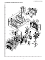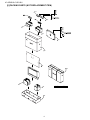
1
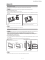
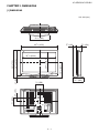
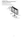
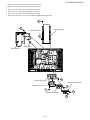
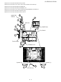
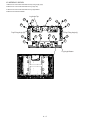
TopPage LC-42D62U/LC-62C42U SERVICE MANUAL No. S86V9LC42D62U LCD COLOR TELEVISION MODELS LC-42D62U LC-62C42U In the interests of user-safety (Required by safety regulations in some countries) the set should be restored to its original condition and only parts identical to those specified should be used. OUTLINE This model is based on the LC-46D62U and is changed some parts. This Service Manual covers the modifications alone. For the other points, refer to the LC-46/52D62U Service Manual. CONTENTS DIFFERENCES FROM BASE MODEL LIST OF CHANGED PARTS ...............................i Parts Guide SAFETY PRECAUTION IMPORTANT SERVICE SAFETY PRECAUTION ...........................................................ii PRECAUTIONS A PRENDRE LORS DE LA REPARATION .............................................. iii PRECAUTIONS FOR USING LEAD-FREE SOLDER ...........................................................iv CHAPTER 1. SPECIFICATIONS [1] SPECIFICATIONS ......................................... 1-1 CHAPTER 2. OPERATION MANUAL [1] OPERATION MANUAL .................................. 2-1 CHAPTER 3. DIMENSIONS [1] DIMENSIONS ................................................ 3-1 CHAPTER 4. REMOVING OF MAJOR PARTS [1] REMOVING OF MAJOR PARTS ................... 4-1 Parts marked with " " are important for maintaining the safety of the set. Be sure to replace these parts with specified ones for maintaining the safety and performance of the set. This document has been published to be used for after sales service only. The contents are subject to change without notice. LC-42D62U/LC-62C42U LC-42D62U/LC-62C42U DIFFERENCES FROM BASE MODEL Service Manual LIST OF CHANGED PARTS Ref. No. PWB ASSEMBLIES MAIN Unit Description LC-46D62U DUNTKD934FM01 TERMINAL Unit DUNTKD935FM01 R/C, LED Unit KEY Unit POWER SUPPLY Unit DUNTKD909FM02 DUNTKD910FM02 RDENCA184WJQZ LC-42D62U/LC-62C42U DUNTKD934FM03 (LC-42D62U) DUNTKD934FM04 (LC-62C42U) DUNTKD935FM03 (LC-42D62U) DUNTKD935FM04 (LC-62C42U) ← ← RDENCA192WJQZ Note Some parts changed Some parts changed No parts changed No parts changed — — — LCD PANEL 42" WIDE LCD Panel Module Unit MAIN Unit R2015 R2022 R2025 R2026 R2078 R2079 Resistor, 4.7k 1/16W Metal Oxide Resistor, 4.7k 1/16W Metal Oxide Resistor, 1k 1/16W Metal Oxide Resistor, 1k 1/16W Metal Oxide Resistor, 10k 1/16W Metal Oxide Resistor, 10k 1/16W Metal Oxide — — VRS-CZ1JF472JY VRS-CZ1JF102FY — VRS-CZ1JF103FY — CABINET AND MECHANICAL PARTS Please refer to a Parts list. PACKING PARTS AND ACCESSORIES Please refer to a Parts list. i R1LK420D3LF21 VRS-CZ1JF472JY — — VRS-CZ1JF102FY — VRS-CZ1JF103FY — Add Delete Delete Add Delete Add LC-42D62U/LC-62C42U LC-42D62U/LC-62C42U SAFETY PRECAUTION Service Manual IMPORTANT SERVICE SAFETY PRECAUTION Service work should be performed only by qualified service technicians who are thoroughly familiar with all safety checks and the servicing guidelines which follow: WARNING • 1. For continued safety, no modification of any circuit should be attempted. Use an AC voltmeter having with 5000 ohm per volt, or higher, sensitivity or measure the AC voltage drop across the resistor. • Connect the resistor connection to all exposed metal parts having a return to the chassis (antenna, metal cabinet, screw heads, knobs and control shafts, escutcheon, etc.) and measure the AC voltage drop across the resistor. 2. Disconnect AC power before servicing. All checks must be repeated with the AC cord plug connection reversed. (If necessary, a nonpolarized adaptor plug must be used only for the purpose of completing these checks.) C A U T I O N : F O R C O N T I N U E D PROTECTION AGAINST A RISK OF FIRE REPLACE ONLY WITH SAME TYPE FUSE. Any reading of 0.75 Vrms (this corresponds to 0.5 mA rms AC.) or more is excessive and indicates a potential shock hazard which must be corrected before returning the monitor to the owner. F701 (125V, 8A) F4702/F4704/F5702 (125V, 7A) F4701/F4703/F5701 (250V, 3A, 115 C) O DVM AC SCALE BEFORE RETURNING THE RECEIVER (Fire & Shock Hazard) 1.5k ohm 10W Before returning the receiver to the user, perform the following safety checks: 3. Inspect all lead dress to make certain that leads are not pinched, and check that hardware is not lodged between the chassis and other metal parts in the receiver. 0.15 µF TEST PROBE 4. Inspect all protective devices such as non-metallic control knobs, insulation materials, cabinet backs, adjustment and compartment covers or shields, isolation resistor-capacitor networks, mechanical insulators, etc. 5. To be sure that no shock hazard exists, check for leakage current in the following manner. • Plug the AC cord directly into a 120 volt AC outlet. • Using two clip leads, connect a 1.5k ohm, 10 watt resistor paralleled by a 0.15µF capacitor in series with all exposed metal cabinet parts and a known earth ground, such as electrical conduit or electrical ground connected to an earth ground. TO EXPOSED METAL PARTS CONNECT TO KNOWN EARTH GROUND /////////////////////////////////////////////////////////////////////////////////////////////////////////////////////////////////////////////////////////////////////////////////////////////////////////////////////////////////////////// SAFETY NOTICE Many electrical and mechanical parts in LCD color television have special safety-related characteristics. For continued protection, replacement parts must be identical to those used in the original circuit. These characteristics are often not evident from visual inspection, nor can protection afforded by them be necessarily increased by using replacement components rated for higher voltage, wattage, etc. The use of a substitute replacement parts which do not have the same safety characteristics as the factory recommended replacement parts shown in this service manual, may create shock, fire or other hazards. Replacement parts which have these special safety characteristics are identified in this manual; electrical components having such features are identified by " " and shaded areas in the Replacement Parts List and Schematic Diagrams. /////////////////////////////////////////////////////////////////////////////////////////////////////////////////////////////////////////////////////////////////////////////////////////////////////////////////////////////////////////// ii LC-42D62U/LC-62C42U PRECAUTIONS A PRENDRE LORS DE LA REPARATION Ne peut effectuer la réparation qu' un technicien spécialisé qui s'est parfaitement accoutumé à toute vérification de sécurité et aux conseils suivants. AVERTISSEMENT • A l'aide de deux fils à pinces, brancher une résistance de 1.5 kΩ 10 watts en parallèle avec un condensateur de 0.15µF en série avec toutes les pièces métalliques exposées du coffret et une terre connue comme une conduite électrique ou une prise de terre branchée à la terre. 1. N'entreprendre aucune modification de tout circuit. C'est dangereux. 2. Débrancher le récepteur avant toute réparation. • Utiliser un voltmètre CA d'une sensibilité d'au moins 5000Ω/V pour mesurer la chute de tension en travers de la résistance. PRECAUTION: POUR LA PROTECTION CONTINUE CONTRE LES RISQUES D'INCENDIE, REMPLACER LE FUSIBLE • Toucher avec la sonde d'essai les pièces métalliques exposées qui présentent une voie de retour au châssis (antenne, coffret métallique, tête des vis, arbres de commande et des boutons, écusson, etc.) et mesurer la chute de tension CA en-travers de la résistance. Toutes les vérifications doivent être refaites après avoir inversé la fiche du cordon d'alimentation. (Si nécessaire, une prise d'adpatation non polarisée peut être utilisée dans le but de terminer ces vérifications.) La tension de pointe mesurèe ne doit pas dépasser 0.75V (correspondante au courant CA de pointe de 0.5mA). Dans le cas contraire, il y a une possibilité de choc électrique qui doit être supprimée avant de rendre le récepteur au client. F701 (125V, 8A) F4702/F4704/F5702 (125V, 7A) F4701/F4703/F5701 (250V, 3A, 115 C) O VERIFICATIONS CONTRE L'INCEN-DIE ET LE CHOC ELECTRIQUE Avant de rendre le récepteur à l'utilisateur, effectuer les vérifications suivantes. 3. Inspecter tous les faisceaux de câbles pour s'assurer que les fils ne soient pas pincés ou qu'un outil ne soit pas placé entre le châssis et les autres pièces métalliques du récepteur. DVM ECHELLE CA 4. Inspecter tous les dispositifs de protection comme les boutons de commande non-métalliques, les isolants, le dos du coffret, les couvercles ou blindages de réglage et de compartiment, les réseaux de résistancecapacité, les isolateurs mécaniques, etc. 1.5k ohm 10W 5. S'assurer qu'il n'y ait pas de danger d'électrocution en vérifiant la fuite de courant, de la facon suivante: • 0.15 µF SONDE D'ESSAI Brancher le cordon d'alimentation directem-ent à une prise de courant de 120V. (Ne pas utiliser de transformateur d'isolation pour cet essai). AUX PIECES METALLIQUES EXPOSEES BRANCHER A UNE TERRE CONNUE ///////////////////////////////////////////////////////////////////////////////////////////////////////////////////////////////////////////////////////////////////////////////////////////////////////////////////////////////////////////// AVIS POUR LA SECURITE Pour assurer la protection, ces pièces doivent être identiques à celles utilisées dans le circuit d'origine. L'utilisation de pièces qui n'ont pas les mêmes caractéristiques que les pièces recommandées par l'usine, indiquées dans ce manuel, peut provoquer des électrocutions, incendies, radiations X ou autres accidents. De nombreuses pièces, électriques et mécaniques, dans les téléviseur ACL présentent des caractéristiques spéciales relatives à la sécurité, qui ne sont souvent pas évidentes à vue. Le degré de protection ne peut pas être nécessairement augmentée en utilisant des pièces de remplacement étalonnées pour haute tension, puissance, etc. Les pièces de remplacement qui présentent ces caractéristiques sont identifiées dans ce manuel; les pièces électriques qui présentent ces particularités sont identifiées par la marque " " et hachurées dans la liste des pièces de remplacement et les diagrammes schématiques. ///////////////////////////////////////////////////////////////////////////////////////////////////////////////////////////////////////////////////////////////////////////////////////////////////////////////////////////////////////////// iii LC-42D62U/LC-62C42U PRECAUTIONS FOR USING LEAD-FREE SOLDER Employing lead-free solder • “PWBs” of this model employs lead-free solder. The LF symbol indicates lead-free solder, and is attached on the PWBs and service manuals. The alphabetical character following LF shows the type of lead-free solder. Example: Indicates lead-free solder of tin, silver and copper. Indicates lead-free solder of tin, silver and copper. Using lead-free wire solder • When fixing the PWB soldered with the lead-free solder, apply lead-free wire solder. Repairing with conventional lead wire solder may cause damage or accident due to cracks. As the melting point of lead-free solder (Sn-Ag-Cu) is higher than the lead wire solder by 40 °C, we recommend you to use a dedicated soldering bit, if you are not familiar with how to obtain lead-free wire solder or soldering bit, contact our service station or service branch in your area. Soldering • As the melting point of lead-free solder (Sn-Ag-Cu) is about 220 °C which is higher than the conventional lead solder by 40 °C, and as it has poor solder wettability, you may be apt to keep the soldering bit in contact with the PWB for extended period of time. However, Since the land may be peeled off or the maximum heat-resistance temperature of parts may be exceeded, remove the bit from the PWB as soon as you confirm the steady soldering condition. Lead-free solder contains more tin, and the end of the soldering bit may be easily corroded. Make sure to turn on and off the power of the bit as required. If a different type of solder stays on the tip of the soldering bit, it is alloyed with lead-free solder. Clean the bit after every use of it. When the tip of the soldering bit is blackened during use, file it with steel wool or fine sandpaper. • Be careful when replacing parts with polarity indication on the PWB silk. Lead-free wire solder for servicing PARTS CODE ZHNDAi123250E ZHNDAi126500E ZHNDAi12801KE PRICE RANK BL BK BM PART DELIVERY J J J DESCRIPTION φ0.3mm 250g (1roll) φ0.6mm 500g (1roll) φ1.0mm 1kg (1roll) iv LC-42D62U/LC-62C42U CHAPTER 1. SPECIFICATIONS LC-42D62U/LC-62C42U Service Manual [1] SPECIFICATIONS Item Model: LC-42D62U/LC-62C42U LCD panel 42" Advanced Super View & BLACK TFT LCD Number of dots 6,220,800 dots (1920 TV Function 1080 3 dots) TV-standard (CCIR) American TV Standard ATSC/NTSC System Receiving Channel VHF/UHF VHF 2-13ch, UHF 14-69ch CATV 1-135ch (non-scrambled channel only) Digital Terrestrial 2-69ch Broadcast (8VSB) Digital cable*1 1-135ch (non-scrambled channel only) (64/256 QAM) Audio multiplex BTSC System Audio out 10W Terminals Rear INPUT 1 AV in, COMPONENT in INPUT 2 AV in, COMPONENT in INPUT 3 S-VIDEO in, AV in INPUT 4 Audio in, HDMI in with HDCP INPUT 5 HDMI in with HDCP ANTENNA 75 2 Unbalance, F Type 1 for Analog (VHF/UHF/CATV) and Digital (AIR/CABLE) DIGITAL AUDIO OUTPUT Optical Digital audio output OUTPUT Audio out OSD language English/French/Spanish Power Requirement AC 120 V, 60 Hz Power Consumption 247 W Weight (approx.) Dimension* 2 (W H D) w/o stand 66.2 lbs./30.0 kg with stand 73.5 lbs./33.3 kg w/o stand 4019/ 32 2637/ 64 with stand 4019/ 32 287/ 8 Operating temperature 1 (PCM/Dolby Digital) 59/ 32 inch 111/ 2 inch + 32°F to + 104°F (0°C to + 40°C) * 1 Emergency alert messages via Cable are unreceivable. * 2 The dimensional drawings are shown on the inside back cover. • As part of policy of continuous improvement, SHARP reserves the right to make design and specification changes for product improvement without prior notice. The performance specification figures indicated are nominal values of production units. There may be some deviations from these values in individual units. 1–1 LC-42D62U/LC-62C42U CHAPTER 2. OPERATION MANUAL LC-42D62U/LC-62C42U Service Manual [1] OPERATION MANUAL Part names TV (Front) Remote control sensor OPC indicator* OPC sensor* SLEEP indicator** POWER indicator** NOTE *OPC: Optical Picture Control. **TV status indicator. TV (Rear) Channel buttons (CH / ) HDMI terminal (INPUT 5) Volume buttons (VOL - / + ) HDMI terminal (INPUT 4) INPUT button POWER button DIGITAL AUDIO OUTPUT terminal Antenna/Cable in AUDIO terminal (INPUT 4) INPUT 3 terminals INPUT 1 terminals AC INPUT terminal INPUT 2 terminals AUDIO OUTPUT terminals 2–1 LC-42D62U/LC-62C42U Part names Remote control unit 1 1 2 3 14 4 2 3 15 5 6 7 16 8 9 10 4 11 12 13 5 6 17 7 18 8 19 9 20 10 21 22 11 23 24 25 26 12 13 27 14 15 16 TV POWER: Switch the TV power on or enters standby mode. DISPLAY: Display the channel information. SOURCE POWER: Turns the power of the external equipment on and off. External equipment operational buttons: Operate the external equipment. 0 _ 9: Set the channel. (DOT): INPUT: Select a TV input source. (TV, INPUT 1, INPUT 2, INPUT 3, INPUT 4, INPUT 5) VOL / : Set the volume. SURROUND: Select Surround settings. FREEZE: Set the still image. Press again to return to normal screen. EXIT: Turn off the menu screen. SLEEP: Set the sleep timer. AUDIO: Selects the MTS/SAP or the audio mode during multi-channel audio broadcasts. FUNCTION: Switches the remote control for TV, CBL/ SAT, VCR, DVD and AUDIO operation. Indicator lights up for the current mode. * To enter the code registration mode, you need to press FUNCTION and DISPLAY at the same time. LIGHT : When pressed all buttons on the remote control unit will light. The lighting will turn off if no operations are performed within about 5 seconds. This button is used for performing operations in low-light situations. VIEW MODE: Select the screen size. 17 ENT: Jumps to a channel after selecting with the 0 _ 9 buttons. 18 FLASHBACK: Return to the previous channel or external input mode. 19 CH / : Select the channel. 20 MUTE: Mute the sound. 21 MENU: Display the menu screen. 22 / / / /ENTER: Select a desired item on the screen. 23 RETURN: Return to the previous menu screen. 24 FAVORITE CH A, B, C, D: Select 4 preset favorite channels in 4 different categories. While watching, you can toggle the selected channels by pressing A, B, C and D. 25 FAVORITE: Register favorite channel. 26 CC: Display captions from a closed-caption source. 27 AV MODE: Select an audio or video setting. (When the input source is TV, INPUT 1, 2 or 3: STANDARD, MOVIE, GAME, USER, DYNAMIC (Fixed), DYNAMIC. When the input source is INPUT 4 or 5: STANDARD, MOVIE, GAME, PC, USER, DYNAMIC (Fixed), DYNAMIC) NOTE When using the remote control unit, point it at the TV. 2–2 LC-42D62U/LC-62C42U Appendix Removing the stand Before detaching (or attaching) stand, unplug the AC cord from the AC INPUT terminal. CAUTION Do not remove the stand from the TV unless using an optional wall mount bracket to mount it. Before attaching/detaching stand Before performing work make sure to turn off the TV. Before performing work spread cushioning over the base area to lay the TV on. This will prevent it from being damaged. 1 2 Hex key Unfasten the four screws used to secure the stand in place. Detach the stand from the TV. (Hold the stand so it will not drop from the edge of the base area.) NOTE To attach the stand, perform the above steps in reverse order. Setting the TV on the wall CAUTION This TV should be mounted on the wall only with the AN-37AG2/AN-52AG1 (SHARP) wall mount bracket. The use of other wall mount brackets may result in an unstable installation and may cause serious injuries. Installing the TV requires special skill that should only be performed by qualified service personnel. Customers should not attempt to do the work themselves. SHARP bears no responsibility for improper mounting or mounting that results in accident or injury. Using an optional bracket to mount the TV You can ask a qualified service professional about using an optional AN-37AG2/AN-52AG1 bracket to mount the TV to the wall. Carefully read the instructions that come with the bracket before beginning work. About setting the TV angle and height adjustment Hanging on the wall AN-37AG2/AN-52AG1 wall mount bracket. 0° or 5° For AN-52AG1 0/5/10/15/20° Vertical mounting - 5/0/ + 5 cm (can be moved 5 cm up or down) Angular mounting AN-37AG2 AN-52AG1 NOTE Detach the cable clamps on the rear of the TV when using the optional mount bracket. 2–3 LC-42D62U/LC-62C42U Basic adjustment settings Menu items for TV/INPUT 1/2/3 Menu items for HDMI (INPUT 4/5) Picture Picture OPC Backlight Contrast Brightness Color Tint Sharpness Advanced Color Temp. Black 3D-Y/C Monochrome Film Mode Range of OPC OPC Backlight Contrast Brightness Color Tint Sharpness Advanced Color Temp. Black Monochrome Film Mode Range of OPC Audio Audio Treble Bass Balance Surround Treble Bass Balance Surround Power Control Power Control No Signal Off No Operation Off No Signal Off No Operation Off Setup Setup Input Skip Input Signal Input Label Position Language Reset EZ Setup CH Setup Antenna Setup-DIGITAL Input Skip Input Label Parental CTRL Position Language Reset Option Audio Only Digital Noise Reduction HDMI Setup Output Select Option Audio Only Digital Noise Reduction Input Select Output Select Color System Caption Setup Program Title Display Favorite CH NOTE Some menu items may not be displayed depending on the selected input source. Digital Setup Audio Setup 2–4 LC-42D62U/LC-62C42U CHAPTER 3. DIMENSIONS LC-42D62U/LC-62C42U Service Manual [1] DIMENSIONS Unit: inch/(mm) 2117/ 64 (540) 4019/ 32 (1031) 325/ 32 (96) 59/ 32 (134) 1637/ 64 (421) 2023/ 32 (526.0) 2637/ 64 (675) 111/ 2 (292) 77/ 8 (200) 77/ 8 (200) 323/ 64 (85) 29/ 32 (58) 287/ 8 (733) 3647/ 64 (933.0) 3–1 LC-42D62U/LC-62C42U Service CHAPTER 4. REMOVING OF MAJOR PARTS LC-42D62U/LC-62C42U Manual [1] REMOVING OF MAJOR PARTS 1. Remove the SD Card Cover. 2. Remove the 4 lock screws and detach the Stand Base Ass'y. 3. Remove the 12 lock screws, 5 lock screws and detach the Rear Cabinet. 3 1 SD Card Cover 3 2 Rear Cabinet Stand Base Ass'y 4–1 LC-42D62U/LC-62C42U 4. Remove the 4 lock screws and detach the Chassis Fixing Angle. 5. Remove the 4 lock screws and detach the Center Angle (L)(R). 6. Remove the 2 lock screws and detach the Stand Assist Angle. 7. Remove the 2 lock screws and detach the Stand Assist Cover. 8. Remove the 4 lock screws and detach the Stand Fixing Angle. 9. Remove the 7 lock screws, 1 lock screw and detach the MAIN Shield and Earth Plate. 5 9 Center Angle (L) Center Angle (R) 9 5 Earth Plate MAIN Shield Stand Fixing Angle 8 Chassis Fixing Angle Stand Assist Cover 6 7 4 Stand Assist Angle 4 4–2 LC-42D62U/LC-62C42U 10.Disconnect all the connectors from all the PWBs. 11.Remove the Top Cover Ass'y. Remove the 1 lock screw from the Top Cover Ass'y and detach the KEY Unit. Top Cover Ass'y KEY Unit 11 10 10 10 10 4–3 LC-42D62U/LC-62C42U 12.Remove the 7 lock screws and detach the Tray Chassis. 13.Remove the 2 lock screws, 3 lock screws, 2 lock screws and detach the Terminal Angle. 14.Remove the 5 lock screws and detach the POWER Unit. 15.Remove the 4 lock screws and detach the TERMINAL Unit. 16.Remove the 3 lock screws, 3 lock screws and detach the MAIN PWB Radiator and MAIN Unit. 17.Remove the 2 lock screws and detach the Speaker (L)(R). 18.Remove the 2 lock screws and detach the R/C, LED Unit. 16 MAIN PWB Radiator 14 16 MAIN Unit 16 13 12 13 POWER Unit Tray Chassis 13 Terminal Angle TERMINAL Unit 15 Speaker (R) Speaker (L) 17 18 R/C, LED Unit 4–4 17 LC-42D62U/LC-62C42U 19.Remove the 4 lock screws and detach the Tray Fixing Angle (L)(R). 20.Remove the 7 lock screws and detach the Lug Angle Top. 21.Remove the 8 lock screws and detach the Lug Angle Bottom. 22.Remove the LCD Panel Module. Lug Angle Top 20 20 20 20 20 19 19 Tray Fixing Angle (R) 19 Tray Fixing Angle (L) 21 21 21 21 19 21 21 Lug Angle Bottom 4–5 LC-42D62U/LC-62C42U PartsGuide PARTS GUIDE No. S86V9LC42D62U Note: The reference numbers on the PWB are arranged in alphabetical order. MODELS LC-42D62U LC-62C42U CONTENTS [1] [2] [3] PRINTED WIRING BOARD ASSEMBLIES (NOT REPLACEMENT ITEM) LCD PANEL (NOTE: THE PARTS HERE SHOWN ARE SUPPLIED AS AN ASSEMBLY BUT NOT INDEPENDENTLY.) DUNTKD934FM03/04 (LC-42D62U/ LC-62C42U) (MAIN Unit) [4] CABINET AND MECHANICAL PARTS [5] SUPPLIED ACCESSORIES [6] PACKING PARTS (NOT REPLACEMENT ITEM) [7] SERVICE JIGS (USE FOR SERVICING) Parts marked with " " are important for maintaining the safety of the set. Be sure to replace these parts with specified ones for maintaining the safety and performance of the set. This document has been published to be used for after sales service only. The contents are subject to change without notice. LC-42D62U/LC-62C42U NO. PARTS CODE PRICE NEW RANK MARK PART DELIVERY DESCRIPTION [1] PRINTED WIRING BOARD ASSEMBLIES (NOT REPLACEMENT ITEM) N N N N N N N DUNTKD934FM03 DUNTKD934FM04 DUNTKD935FM03 DUNTKD935FM04 DUNTKD909FM02 DUNTKD910FM02 RDENCA192WJQZ CQ CQ BH AQ AH BU N N N N N N N R R X X X X X MAIN Unit MAIN Unit TERMINAL Unit TERMINAL Unit R/C, LED Unit KEY Unit POWER Unit [LC-42D62U] [LC-62C42U] [LC-42D62U] [LC-62C42U] [2] LCD PANEL (NOTE: THE PARTS HERE SHOWN ARE SUPPLIED AS AN ASSEMBLY BUT NOT INDEPENDENTLY.) N R1LK420D3LF21 EQ X 42" WIDE LCD Panel Module Unit [3] DUNTKD934FM03/04 (LC-42D62U/LC-62C42U) (MAIN Unit) R2015 R2026 R2079 VRS-CZ1JF472JY VRS-CZ1JF102FY VRS-CZ1JF103FY AA AA AB J J J Resistor, 4.7k 1/16W Metal Oxide Resistor, 1k 1/16W Metal Oxide Resistor, 10k 1/16W Metal Oxide 2 LC-42D62U/LC-62C42U [4] CABINET AND MECHANICAL PARTS 3 3-1 8 3-2 KEY Unit 34 51 20 47 1-10 40 22 41 36 1 20 1-7 1-7 1-1 1-9 1-5 41 1-7 1-7 1-6 37 1-7 1-7 47 1-10 1-3 48 2 44 14 42 26 1-9 1-8 1-8 1-9 1-8 1-9 44 43 1-4 21 2-2 43 39 POWER Unit 2-1 R/C, LED Unit 1-2 21 43 45 43 52 38 43 6 43 16 43 43 49 6-2 7-1 48 6-1 7-2 48 7 9-2 43 45 43 31 53 43 19 18 45 24 11 45 33 9-3 43 50 16 17 29 27 12 15 23 TERMINAL Unit 5 46 32 10 13 4 54 25 48 48 48 3 43 43 43 56 30 55 9-1 56 45 30 9-3 9-3 43 48 MAIN Unit 28 9-4 9-4 9 48 43 45 35 48 LC-42D62U/LC-62C42U NO. PARTS CODE PRICE NEW RANK MARK PART DELIVERY DESCRIPTION [4] CABINET AND MECHANICAL PARTS 1 1 1-1 1-2 1-3 1-4 1-5 1-6 1-6 1-7 1-8 1-9 1-10 2 2-1 2-2 3 3-1 3-2 4 4 5 6 6-1 6-2 7 7-1 7-2 8 9 9-1 9-2 9-3 9-4 10 11 12 13 14 14 15 16 17 18 19 20 21 22 23 24 25 26 27 28 29 30 31 32 33 34 35 36 37 38 39 40 41 42 43 44 45 46 47 48 49 50 51 52 53 54 55 56 CCABAB600WJ01 CCABAB600WJ02 Not Available Not Available Not Available Not Available Not Available HPNLSA090WJSA HPNLSA090WJSB PSPAHB027WJZZ Not Available Not Available Not Available CCABBA943WJ01 Not Available LHLDWA131WJKZ CCOVAB914WJ01 Not Available JBTN-A614WJKA CDAi-A327WJ01 CDAi-A327WJ03 CDAi-A328WJ01 CANGKA839WJ01 Not Available LHLDWA120WJKZ CANGKA840WJ01 Not Available LHLDWA120WJKZ R1LK420D3LF21 CCHSMA341WJ02 Not Available LHLDWA102WJKZ LHLDWA120WJKZ LHLDWA123WJKZ GCOVAA678WJKA GCOVAB912WJKA HiNDPB715WJSA HiNDPB893WJSA HiNDPB993WJSA HiNDPB994WJSA LANGKA820WJFW LANGKA841WJFW LANGKA879WJFW LANGKA881WJFW LANGKA882WJFW LX-HZA003WJFN LANGTA401WJFW LHLDWA141WJZZ LHLDWA150WJKZ LHLDZA806WJKZ LX-BZA146WJF7 LX-BZA147WJF8 LX-NZ3047GEZZ PRDARA390WJFW PSLDMA910WJN1 PSPAZA917WJKZ PSPAZB192WJKZ QCNCWA496WJZZ QCNW-E249WJPZ QCNW-E897WJQZ QCNW-E899WJQZ QCNW-F017WJQZ QCNW-F018WJQZ QCNW-F019WJQZ QCNW-F020WJQZ QPWBHD978WJQZ RSP-ZA201WJZZ Not Available XBBS740P06000 XBPS930P08JS0 XBPS730P06WS0 XBPS930P08000 XEBS930P10000 XEBS940P20000 LHLDW1141CEZZ PMLT-A390WJZZ PSLDMB066WJZZ RCORFA020WJZZ QEARPA228WJFW XEBS930P08000 PCLiCA008WJZZ LBSHZA005WJZZ - AF - AY AB AZ AB EQ BA AB AB AB AG N N N N N N N N N N N N N N N N N N N N N N N N N AF AH AH AH AK AM AU AL AM AS AD AC AC AC AE AB AM AV AK AG AK AH AF AP AH AM AN AQ AY AZ AA N N N N N N N N N N N N N N N N N N N N AB AA AA AA AE N N AN S AA S AB X X X X X X X X X X X X X X X X X X X X X X X X X X X X X X X X X X X X X X X X X X X X X R R R X X R X X X X X X X X X J X X J X X X J Front Cabinet Ass'y Front Cabinet Ass'y Front Cabinet LED Cover Front Cover Badge, "SHARP" Shaine Trim SP-Net SP-Net Spacer, x6 Spacer, x3 Spacer, x4 Screw, x4 Rear Cabinet Ass'y Rear Cabinet Wire Holder (RWC-30SB) Top Cover Ass'y Top Cover Operation Button Stand Base Ass'y Stand Base Ass'y Stand Support Ass'y Lug Angle Top Ass'y Lug Angle Top Wire Holder Lug Angle Bottom Ass'y Lug Angle Bottom Wire Holder, x8 42" WIDE LCD Panel Module Unit Tray Chassis Ass'y Tray Chassis Wire Holder Wire Holder, x4 Wire Holder, x2 SD Card Cover Stand Assist Cover Terminal Label Jack Indicator Model Label Model Label Terminal Angle Tray Fixing Angle, x2 Stand Fixing Angle Stand Assist Angle Chassis Fixing Angle-A Screw, x2 (for SP) Center Angle, x2 Wire Holder (for LCD INV) Wire Holder (for IF PWB) Wire Holder (for Radiator) Screw, x4 (for Stand Ass'y) Screw, x4 (for Stand) Nut Heat Sink (for MAIN PWB) MAIN Shield Cool Sheet, x2 Cool Sheet Connecting Cord (F-RCA) Connecting Cord (Tuner) Connecting Cord (KM) Connecting Cord (LP) Connecting Cord (SP) Connecting Cord (RA) Connecting Cord (PH, PD) Connecting Cord (LA) Connecting Cord (LV) Speaker, x2 No. Label Screw, x33 (for Ang) Screw, x5 (for Cab-B) Screw, x24 (for Ang, x7/PWB, x17) Screw, x2 (for HDMI) Screw, x3 (for LED, x2/SOUSA, x1) Screw, x22 (for Cab-B) Wire Holder (for LV) Spacer Shield, x2 Core Earth Plate Screw, x3 (for Jack) Rivet Clip, x2 4 [LC-42D62U] [LC-62C42U] [LC-42D62U] [LC-62C42U] [LC-42D62U] [LC-62C42U] [LC-42D62U] [LC-62C42U] LC-42D62U/LC-62C42U [5] SUPPLIED ACCESSORIES X1 AC Cord X2 X3 X6 Operation Manual NO. PARTS CODE X7 X8 "AAA" Size Battery PRICE NEW RANK MARK X4 Cable Clamp Remote Control Unit PART DELIVERY Cable Band X10 Stand Unit DESCRIPTION [5] SUPPLIED ACCESSORIES ! X1 X2 X3 X4 X5 X6 X6 X7 X8 X8 X9 X10 QACCDA039WJPZ RRMCGA535WJSA LHLDWA131WJKZ LHLDWA083WJ00 TCADEA208WJZZ TiNS-C762WJZZ TiNS-C763WJZZ Not Available CDAi-A327WJ02 CDAi-A327WJ04 TCAUHA184WJZZ LHLDWA012WJKZ AR BA AE AD AQ AM - N N N N N N AD AC X X J X X X X X X X J AC Cord Remote Control Unit Cable Clamp Cable Band Enquete Card Operation Manual Operation Manual "AAA" Size Battery Stand Unit Stand Unit Setup Guide Wire Holder 5 [LC-42D62U] [LC-62C42U] [LC-42D62U] [LC-62C42U] [LC-62C42U] LC-42D62U/LC-62C42U [6] PACKING PARTS (NOT REPLACEMENT ITEM) S11 S10 S4 S6 S7 S8 S9 S13 S4 S5 S1 S3 S12 S4 S4 S2 6 LC-42D62U/LC-62C42U NO. PARTS CODE PRICE NEW RANK MARK PART DELIVERY DESCRIPTION [6] PACKING PARTS (NOT REPLACEMENT ITEM) S1 S1 S2 S3 S4 S5 S6 S6 S7 S8 S9 S10 S11 S12 S13 SPAKCD081WJZZ SPAKCD082WJZZ SPAKCD085WJZZ SPAKPA774WJZZ SPAKXB298WJZZ SPAKFB110WJZZ SPAKFB111WJZZ SPAKFB112WJZZ SPAKPA780WJZZ SPAKPA781WJZZ SSAKHA020WJZZ SSAKA0101GJZZ SSAKAA032WJZZ TLABKA009WJZZ SPAKPA602WJZZ - N N N N N N N N N N - Packing Case Packing Case Packing Case (Bottom) Wrapping Paper (Monitor) Packing Add. Packing Case (Stand) Stand Pad Stand Pad Wrapping Paper (Mirror Mat Base) Wrapping Paper (Mirror Mat Sup) Polyethylene Bag (for Screw) Polyethylene Bag Polyethylene Bag No. Label Wrapping Paper (Mirror Mat B) RCA Cable L=1500mm, Tuner Extension 12pins L=1000mm, Main to Power Unit PH (PA) 6pins L=1000mm, Main to Power Unit PD (MI) 41pins L=400mm, Main to LCD Controller Unit (LV) 14pins L=1300mm, Main/Power to Inverter Unit LA (LB) 20pins L=1000mm, Main to LCD Controller Unit (LP) 45pins FFC L=1000mm, LCD Controller Unit to LCD panel, X 4pcs used [7] SERVICE JIGS (USE FOR SERVICING) N N N N N N N N N QCNW-C799WJPZ QCNW-D483WJQZ QCNW-E068WJQZ QCNW-E134WJQZ QCNW-F177WJQZ AG AX AS BG BA J J J J J QCNW-F178WJQZ QCNW-F197WJQZ AW AR J J 7 [LC-42D62U] [LC-62C42U] [LC-42D62U] [LC-62C42U] [LC-42D62U] LC-42D62U/LC-62C42U COPYRIGHT 2006 BY SHARP CORPORATION ALL RIGHTS RESERVED. No part of this publication may be reproduced, stored in a retrieval system, or transmitted in any form or by any means, electronic, mechanical, photocopying, recording, or otherwise, without prior written permission of the publisher. TQ2052-S Sep. 2006 Printed in Japan Design and Production Information Design: Japan Production: SEMEX SY. KD SHARP CORPORATION AV Systems Group CS Promotion Center Yaita, Tochigi 329-2193, Japan