1
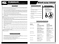
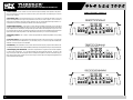
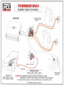
POWER
AMPLIFIER
OWNER’S
MANUAL
POWER AMPLIFIER OWNER’S MANUAL
ENGLISH
Introduction
CONGRATULATIONS...
HOW TO USE THIS MANUAL
on your purchase of a new MTX Audio
Thunder Amplifier! MTX has long been the
industry leader in mobile enclosures and
speakers, and we have reached new heights
with the development of the new MTX
Thunder amplifiers. You couldn’t have chosen
a more reliable, powerful, or better performing amplifier. In fact, we back up every
Thunder amplifier with a three-year warranty
if installed by an authorized MTX Audio retailer (see the warranty statement).
If you are installing this amplifier yourself, we recommend that you read the manual cover-to-cover
before you install it. Familiarize yourself with the
features and details on the input and output panels.
Make sure you have all the equipment you need.
Then follow the step-by-step installation instructions included. Sample installation diagrams may be
found on our website:
Your new MTX Thunder amplifier was
designed, built and thoroughly tested at our stateof-the-art electronics manufacturing facility. We
manufacture every amplifier using the latest
Intelligent Surface Mount Technology. Some of the
advantages of the new design are its significant
improvements to the amplifier’s electrical and
mechanical properties. ISMT devices feature substantially shorter internal and external lead lengths.
This reduces stray capacitance and inductance,
which results in cleaner and more accurate musical
reproduction with significantly less noise interference. The ISMT mounter produces amplifier boards
with smaller and lighter components, which are
more resistant to vibrations inherent in the automotive environment.
A word about power ratings. It is important for you
to know how they stack up. MTX has chosen the
most honest, most conservative way to rate our
amps. We show you the RMS power, at 12.5 volts,
and dynamic power at 14.4 volts. However, we go
above and beyond the call of duty. We test each
amplifier. The technician records the “actual”
power output, and records this number on your
Certified Performance Certificate. The amplifier
must meet or exceed the rated specification before
we’ll ship it. No questions. No exceptions.
We want to ensure you get continuous high performance from your MTX Thunder amplifier, so we
recommend that you have it professionally installed
by your authorized MTX dealer.
2
Features
mtx.com
• Thunder Amplifiers are Covered by 1 or More of
the Following United States of America Patents:
#5,598,325, #5,631,608, #5,783,970.
• Acoustically Seamless Turn-On/Turn-Off
• Adjustable Input Sensitivity
• Anti-Shock PCB Mounting Design
• High Powered Transformer
• Intelligent Surface Mount Technology
• Nickel-Plated, Heavy Duty Terminal
Block Connectors
• Patented PWM MOSFET Switching Power Supply
• Real Time Computerized Protection Circuit
• Unique Rubber Insulated Iso-Feet™
• 12dB/Octave Stereo High Pass, 24dB/Octave
Mono Low Pass Crossover
• Bridgeable Circuit Design
• Buffered RCA Output for Daisy-Chaining
Multiple Amplifiers
• Input Select Switch Functions as a
Built-In Y Connector
• Non-Faded Summed RCA Output
• Patented Class A 100% Discrete Driver
Circuit Topology
• Patented Pure N-Channel Design
• Thunder EQ Bass Enhancement
If you have any questions, write or call us:
MTX Audio
4545 E. Baseline Rd. Phoenix, AZ 85042
602-438-4545 • 800-CALL MTX
[email protected]
mtx.com
Please take a moment to register your purchase
on-line at mtx.com.
Please also record the serial number of your
amplifier in the space provided below and keep this
manual for future reference, as well as your sales
receipt as proof of ownership. (The serial number
of your amplifier is marked on the bottom of its
metal chassis.)
SERIAL NUMBER:
DATE OF PURCHASE:
Specifications
THUNDER564
THUNDER1004
• RMS Power measured at 12.5 Volts DC:
45 Watts x 4 into a 4 Ohm load with less than 0.3% Thd+N
90 Watts x 4 into a 2 Ohm load with less than 0.3% Thd+N
180 Watts x 2 bridged into a 4 Ohm load with less than 0.3% Thd+N
• Dynamic Power measured at 14.4 Volts DC:
70 Watts x 4 into a 4 Ohm load
140 Watts x 4 into a 2 Ohm load
280 Watts x 2 bridged into a 4 Ohm load
• Signal to Noise Ratio: ≥110dB A-Weighted
• Damping Factor: >200
• Frequency Response: 20Hz-20kHz ± 0.25dB
• Maximum Input: 8Vrms
• Thunder EQ: Variable Bass Boost (0-18dB) centered at 40Hz
• Crossover: Variable 40Hz to 200Hz, 12dB/Octave Stereo
High Pass, 24dB/Octave Mono Low Pass, or Full Range
• Dimensions: 13.9" x 9.75" x 2.1" (35.4cm x 24.8cm x 5.3cm)
• RMS Power measured at 12.5 Volts DC:
90 Watts x 4 into a 4 Ohm load with less than 0.3% Thd+N
180 Watts x 4 into a 2 Ohm load with less than 0.3% Thd+N
360 Watts x 2 bridged into a 4 Ohm load with less than 0.3% Thd+N
• Dynamic Power measured at 14.4 Volts DC:
125 Watts x 4 into a 4 Ohm load
250 Watts x 4 into a 2 Ohm load
500 Watts x 2 bridged into a 4 Ohm load
• Signal to Noise Ratio: ≥110dB A-Weighted
• Damping Factor: >200
• Frequency Response: 20Hz-20kHz ± 0.25dB
• Maximum Input: 8Vrms
• Thunder EQ: Variable Bass Boost (0-18dB) centered at 40Hz
• Crossover: Variable 40Hz to 200Hz, 12dB/Octave Stereo
High Pass, 24dB/Octave Mono Low Pass, or Full Range
• Dimensions: 17.8" x 9.75" x 2.1" (45.3cm x 24.8cm x 5.3cm)
THUNDER684
• RMS Power measured at 12.5 Volts DC:
60 Watts x 4 into a 4 Ohm load with less than 0.3% Thd+N
120 Watts x 4 into a 2 Ohm load with less than 0.3% Thd+N
240 Watts x 2 bridged into a 4 Ohm load with less than 0.3% Thd+N
• Dynamic Power measured at 14.4 Volts DC:
85 Watts x 4 into a 4 Ohm load
170 Watts x 4 into a 2 Ohm load
340 Watts x 2 bridged into a 4 Ohm load
• Signal to Noise Ratio: ≥110dB A-Weighted
• Damping Factor: >200
• Frequency Response: 20Hz-20kHz ± 0.25dB
• Maximum Input: 8Vrms
• Thunder EQ: Variable Bass Boost (0-18dB) centered at 40Hz
• Crossover: Variable 40Hz to 200Hz, 12dB/Octave Stereo
High Pass, 24dB/Octave Mono Low Pass, or Full Range
• Dimensions: 15.6" x 9.75" x 2.1" (39.7cm x 24.8cm x 5.3cm)
3
POWER AMPLIFIER OWNER’S MANUAL
Installation
Any deviation from the connection specifications recommended may cause serious damage to the amplifier,
speakers and/or vehicle electrical system. Please double-check the connection before turning the system on.
1. Disconnect the vehicle’s negative battery connection.
2. Place your Thunder amplifier at the predetermined mounting location. Using a felt pen, mark the exact
position of the mounting holes on the mounting surface. Set the amplifier aside. Use a sharp, precise blade
to cut small circles in the carpet and padding around the four marks denoting your mounting holes to
expose the metal underneath. Use a center punch to make an indentation in the metal to ensure that you
drill the exact position for the screws. Drill the four holes as marked.
3. Temporarily mount your Thunder amplifier using the four (4) screws provided.
4. Run a power cable from the vehicle’s battery through the firewall and through the interior of the vehicle
connecting one end to your Thunder amplifier’s +BATT terminal and connect the other end to the positive
post on the battery.
Note: Install a circuit breaker/fuse within 18" of the battery. This effectively lowers the risk of severe damage
to your vehicle should a short circuit ever occur in the audio system. Do not install the fuse in the fuse holder until all installation steps have been completed.
5. Find a good ground spot on the vehicle’s chassis and remove the paint to reveal bare metal at the contact
point. Attach the ground wire to that contact point and connect the other end of the ground wire to the
GND terminal of your Thunder amplifier.
6. Connect a Remote Turn-on wire from your source unit to your Thunder amplifier’s REM terminal (14 or 16
gauge wire). If your source unit does not have a dedicated Remote Turn-on lead, you may connect to the
source unit’s Power Antenna lead.
7. Connect RCA cables from your source unit to your Thunder amplifier’s RCA input jacks. If RCA (low level)
output is not available, connect the included speaker (high level) connector to the speaker wires from the
source unit.
8. Connect your speakers to your Thunder amplifier’s speaker terminals using 12 gauge minimum speaker
cable.
9. Double-check all the previous installation steps, in particular, the wiring and component connections.
Securely mount the amplifier. If everything is in order, reconnect the vehicle’s negative battery connection and begin adjusting your amplifier.
Note: Be sure that the Gain Level on the amplifier is turned all the way down (counter clockwise) before proceeding with adjustments.
Common Oversights
•
•
•
•
4
The battery ground should remain DISCONNECTED at all stages of installation.
Do not begin drilling until you have put your Thunder amplifier aside. Using the amplifier as a drilling guide
may cause irreparable damage to the amplifier and void your warranty.
Do not route any wires underneath or outside the vehicle body.
Route signal wires (RCAs from source unit, speaker wires, etc.) away from power wires (power, ground,
etc.) to avoid ground loops and other sources of noise.
Adjusting the Gain
Typical Speaker
Wiring Configurations
1. Turn the gain control on the amplifier all the way
down.
2. Turn up the volume control on the source unit to
approximately 3⁄4 of maximum.
3. Adjust the gain control on the amplifier until
audible distortion occurs.
4. Adjust the gain control down until audible distortion disappears.
5. Follow steps 3-4 for other gain control settings if
applicable.
6. The amplifier is now calibrated to the output of
the source unit.
Stereo Amplifier
Bridge Mode Application
Impedance Requirement
4 ohm bridge minimum
2 ohm stereo minimum
8 ohm
4 ohm
8 ohm
4 ohm
+ - - +
L L R R
+ - - +
L L R R
AMP
AMP
Two 8 ohm Speakers
Two 4 ohm Speakers
OK
not
ok
Troubleshooting Guide
Read this if you wanna be a do-it-yourselfer or give us a call at 800-CALLMTX.
PROBLEM
CAUSE
SOLUTION
No LED indication
No +12V at remote connection
No +12V at Power connection
Insufficient ground connection
Blown power fuse
Supply +12V to terminal
Supply +12V to terminal
Verify ground connection
Replace fuse
LED on, no output
Volume on head unit off
Speaker connections not made
Gain control on amplifier off
Signal processing units off
All speakers blown
Increase volume on head unit
Make speaker connections
Turn up gain
Apply power to signal processor
Replace speakers
Output distorted
Head unit volume set too high
Amplifier gain set too high
Lower head unit volume
Lower amplifier gain
Balance reversed
Speakers wired L + R reversed
RCA inputs reversed
Wire speakers with correct
orientation
Reverse RCA input
Some balance reversed
Some Speakers wired L + R
reversed
Some RCA inputs reversed
Wire speakers with correct
orientation
Reverse appropriate RCA inputs
Bass is weak
Speakers wired out
of phase
Not using MTX woofers
Wire with correct phase
Buy MTX woofers
Blowing fuses
Excessive output levels
Amplifier defective
Lower volume
Return for service
5
POWER AMPLIFIER OWNER’S MANUAL
1. Gain Controls – These controls are used to match the input sensitivity of the amplifier to the particular source unit that you are using. The controls are factory set to 1Vrms. Note: The separate gain control for
front and rear channels.
Input Panel Layout
2. RCA Input Jacks – These RCA input jacks are for use with source units that have RCA or Line Level
Outputs. An independent set of jacks are provided for front and rear stereo inputs. A source unit with a
minimum level of 200mV is required for proper operation. The use of high quality twisted pair cables is recommended to decrease the possibility of radiated noise entering the system.
3. Input Select 2CH/4CH – This switch, is used to match the amplifier’s input to the source unit’s output
so all four channels of the amplifier are driven. If your source unit has 2 outputs (a left and right) connect them
to the amplifier’s front channel inputs, and place the input select switch in the 2CH position. If your source unit
has 4 outputs, (left front, left rear, and right front, right rear) connect them to the amplifier inputs and place the
input select switch in the 4CH position. In the 4CH position, the fader on your source unit will operate.
❶❻ ❹ ❺
4. Frequency Control – This control is continuously adjustable from 40Hz through 200Hz. Factory setting
is at 40Hz.
❸
❷ ❼ ❷ ❺ ❹❻ ❶
❸
❷ ❼ ❷ ❺ ❹❻ ❶
❸
❷ ❼ ❷ ❺ ❹❻ ❶
5. Crossover Select – This switch determines what type of signal comes out of the amp. If you select high
pass, the crossover slope is 12dB/stereo. If you select low pass, your crossover slope will be 24dB/mono.
Available crossover frequencies are 40-200Hz.
6. Thunder EQ – This equalization circuit is used to enhance the low frequency response of the vehicle’s interior. With up to 18 dB of boost and centered at 40Hz, the Bass EQ can be adjusted to meet your own personal taste.
7. RCA Output Jacks and Switch – These RCA outputs allow for a signal to be sent to other amplifiers
in a daisy-chain configuration.. You can select whether the signal should be high pass , low pass or full
range. In low pass mode, the RCA outputs allow for multiple bass amplifiers to be level controlled using one
EBC. The RCA output jacks provide a line level full-range summed output of the Right Front/Right Rear and
Left Front/Left Rear input signals.
❶ ❻❹ ❺
❶ ❻❹ ❺
6
7
POWER AMPLIFIER OWNER’S MANUAL
1. Fuses - For convenience, all amplifiers utilize ATC type fuses. For continued protection in the event that
a fuse blows, replace the fuse only with the same value.
Caution: The power fuses on the amp are for protecting the amp against overdrive. To protect the vehicle’s
electrical system, an additional fuse is required within 18" of the battery on the 12V+ cable.
Output Panel Layout
Thunder564 - 25A x 3
Thunder684 - 35A x 3
Thunder1004 - 150 Amps (not supplied)
❺
2. Power Terminal – This is the main power input for the amplifier and must be connected directly to the
positive terminal of the car battery for the amplifier to operate properly. See the chart below for recommended cable sizes for each amplifier. Use caution when running this cable through the car. Try to avoid
the input RCA cables, antenna cabling, or other sensitive equipment as the large amount of current flowing
through this cable can induce noise into your system. It is also very important to have a tight connection to
ensure maximum performance.
❶
❷❹❸
Thunder564 – 6 - 8 Gauge
Thunder684 – 6 - 8 Gauge
Thunder1004 – 1/0 Gauge only
3. Ground Terminal – A good quality ground is required for your Thunder Amplifier to operate at peak
performance. A short length of cable the same gauge as your power cable should be used to attach the
ground terminal directly to the chassis of the car. Always scrape or sand any painted surfaces to expose
bare metal where the ground wire will attach.
❺
4. Remote Terminal – All Thunder Amplifiers can be turned on by applying 12 volts to this terminal.
Typically this voltage is supplied by a wire from the source unit marked “remote” or “electric antenna”.
❶
5. Speaker Terminals – As shown in the wiring diagrams, be sure to observe speaker polarity through
the system. Failing to wire the speakers in proper phase could result in a loss of bass response and/or poor
overall sound quality. Caution: Thunder amplifiers are not recommended for loads below 2 ohms stereo or 4
ohms bridged.
❷ ❹❸
6. Power LED (top of heatsink)- A lighted LED indicates that power has been applied to the amplifier.
+12V from the battery to the +BATT terminal and +12V from a switched ignition or remote lead from a head
unit. An unlighted LED indicates power has been removed or the amplifier has overheated. In the case of
the overheat condition, the amplifier will turn back on after it cools down.
❺
❹
❸
8
❷
9
POWER AMPLIFIER OWNER’S MANUAL
Warranty
NOTES
All MTX Audio Thunder Amplifiers purchased in the United States from an authorized MTX dealer are
guaranteed against defects in material and workmanship for a period of three years from the date purchased
by the end user if the product is installed by an authorized MTX dealer, and one year if installed by the
consumer. This warranty is limited to the original retail purchaser of the product.
Product found to be defective during that period will be repaired or replaced by MTX at no charge. This
warranty is void if it is determined that unauthorized parties have attempted repairs or alterations of any
nature. Warranty does not extend to cosmetics or finish. Before presuming a defect is present in the product, be certain that all related equipment and wiring is functioning properly. MTX disclaims any liability for
other incurred damages resulting from product defects. Any expenses incurred in the removal and reinstallation of products are not covered by this warranty. MTX's total liability will not exceed the purchase price
of the product. If a defect is present, your authorized MTX dealer may be able to effect repairs.
Proof of purchase is required when requesting service, so please retain your sales receipt. and take
a moment to register your warranty on-line @ www.mtx.com.
For Warranty Inquiries, please call:
800-CALL MTX
602-438-4545
MTX Audio
4545 E. Baseline Rd.
Phoenix, Arizona 85042
Register Warranty On-line:
mtx.com
34
35
The Pointe at South Mountain
4545 East Baseline Road
Phoenix, AZ 85042
602-438-4545
800-CALL MTX
mtx.com
© 2002 MTX. All rights reserved. MTX and Thunder are trademarks of MTX.
Due to continual product development, all specifications are subject to change without notice.
MTX001343 RevB 10/02
NDM251