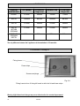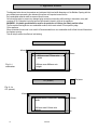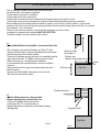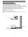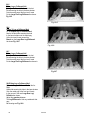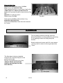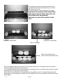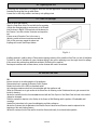
1
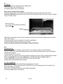
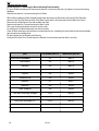
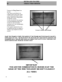
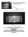
CRYSTAL FIRES
(BOSTON/MIAMI) Cf1 and MANHATTAN
Inset Conventional
Flue Fire
USER INSTALLATION AND
SERVICING INSTRUCTIONS
FOR USE WITH NATURAL GAS
G20 @ 20 mbar
For use in GB and IE
CE
THESE INSTRUCTIONS MUST BE LEFT
WITH THE USER FOR FUTURE REFERENCE
1
issue 5
Users instructions
Section
No
page
No
1) important notes
2) How to light and operate remote control system
3) Cleaning and simple maintenance
4) Spares and service
5) User replaceable parts
3
4
7
7
7
Installation instructions
Section
No
page
No
6) parts supplied/box contents
7) Installation requirements
8) Technical data
9) Dimensions
10) Contents of fixing kit
11)Appliance location
12)Flue requirements and builders opening requirements
13)Surround requirements
14)Ventilation
15)Gas requirements
16)Installation of fire
17)Commissioning the fire
18)Fuel effect - logs and driftwood layouts
19)Fuel effect - pebbles layout
20)Lighting the fire
21)Checking for spillage
22)Instruct the user
23)Service and maintenance
24)Spare parts
25)additional pages for single trim version
These instructions cover appliances the cf1 (miami )and manhattan
The only difference being the manhattan is 150 mm taller
Thank you for purchasing a crystal gas fire you are now a proud owner of a crystal
cf1(miami) /manhattan which if serviced annually will provide years of trouble free
service
2
issue 5
8
8
9
10
10
11
12
13
14
14
14
16
17
20
22
22
22
23
26
27
CRYSTAL CF1/MANHATTAN
USERS INSTRUCTIONS
1.IMPORTANT NOTES
1:1
This fire should be installed and serviced every 12months in accordance with current gas safety
(installation and uses) regulations by a competent person who is a member of a recognised gas installer’s
organisation (e.g. Gas safe ) and in accordance with the installation instructions.
1:2
The flue should be inspected before your appliance is installed and checked annually to ensure continuous
clearance of combustion products and safe operation.
Where solid fuel has been used the chimney must be swept before installation.
1:3
UNDER NO CIRCUMSTANCES must the fire be used if the glass door panel is broken cracked or
damaged
1:4
IMPORTANT.
The glass panel door and other outer parts, (e.g. outer frame and door) will become hot in use; clothes
etc., should not be wrapped over or near the fire and we recommend that a ‘fire guard conforming to BS
8423 should be used for the protection of young children the elderly the infirm and pets’.
1:5
DO NOT burn paper or rubbish in the fire.
1:6
It is important for the safe operation and to maintain efficiency that the fire is not operated with damaged or
broken fuel effect pieces or ceramics.
UNDER NO CIRCUMSTANCES should extra fuel effect pieces be used.
1:7
When the fire is first used it may emit a slight odour or smoke, this is due to the newness and will
disappear. DO NOT WASH OR VACUUM the Fuel Effect ceramic pieces.
1:8
The fire MUST be installed into a Builders Opening in line with the Installation Instructions.
No combustible material should be placed within 150mm of the appliance
Any combustible material above the opening should be removed up to a height of
500mm. any shelf above the fire should not project more than 150mm forward.
For deeper shelves allow a 15mm increase in height for every 25mm in depth.
1:9
These instructions are intended to assist you in the correct operation of your appliance and
Should be kept safe for future reference
3
issue 5
2. How to light and operate
SAFETY: - The fire is fitted with a flame supervision and atmosphere sensing device (Oxy pilot) that will shut off the gas
supply if the pilot light should go out for any reason. It will extinguish the pilot light if the oxygen content in the room falls
below a prescribed level.
If the pilot light keeps going out seek expert help.
2:0
WARNING: - If the fire is extinguished and the control is not in the off position, the control should Be returned to the off
position and no attempt should be made to relight the fire until 3 minutes have Elapsed. If the pilot cannot be relit seek expert
help.
The batteries required to operate the control system should have been fitted by the installer
The Installer may have left the fire at the pilot setting and it is important that you read the
Section headed ‘Lighting the Pilot’ if you decide to turn off the pilot and prefer to relight it each time You use the fire.
2:1
Lighting the Pilot.
You will find this operation quite simple if you
Refer to Fig 2:1 showing the Buttons on the
Remote Control Handset and read this section
Before Lighting the Fire.
Open the outer door of the fire and the control can be
seen at the base of the fire.
Making reference to figure 2:1a familiarise yourself with
the knobs.
First check that Control knob ‘B’ is set at the maximum
setting.
Secondly check that Control knob ‘A’ is set at the off
position as shown in the picture.
It will be necessary to see the pilot and it is visible at
the front left centre of the fuel bed, see Fig 2:1b.
To light the pilot turn Knob ‘A’ to the Pilot Ignition
Star Setting and keep the knob pushed in for 5
seconds before turning the knob further to operate
the Piezo Igniter.
You will hear a click and see a spark at the pilot and
the pilot should light.
If it does not light turn the knob back to off setting and
repeat the operation. (This may take several attempts
on the first lighting).
Pilot position shown above at cut out on left
side
Fig 2:1b
4
issue 5
Once the pilot has lit do not release the knob,
keep It held in for a further 15seconds.
You can then release the knob and the pilot flame should stay alight.
If it goes out turn the knob back to the off setting and repeat the operation but once the pilot flame is lit hold the knob
in a little longer before releasing it.
Now turn the Knob ‘A’ as far as it will turn to the maximum flame setting.
The main burner will now light at the maximum setting.
The fire is now lit so you can close the outer door and operate the fire using the remote control handset.
And read the section headed ‘Choosing your heat setting’.
You do not need to light the pilot every time you light the fire. You can leave the pilot lit all the time if the property is
occupied. This way the fire can be totally operated by the remote control handset.
If the fire cannot be lit then seek expert help.
Keeping the pilot lit keeps the chimney warm and helps reduce condensation marks on the door glass panel.
2:2
Turning the Pilot Off.
If you decide to turn the pilot off wait until the fire is cool and open the outer door.
Now simply turn Knob ‘A’ to the off setting.
You will not be able to relight the fire or turn the knob for at least 10seconds as the control as a built in safety lock.
Do not force the knob, as this will damage the control. Wait until the safety lock as released.
2:3
Choosing your heat setting.
There are 2 arrows on the remote control handset, with the fire at the maximum setting point the remote control at
the fire and press the bottom arrow to reduce the heat setting the flame heights will lower.
(It is necessary to press the top button and the small button on the left together to increase the heat setting,
this is a safety feature)
Over time you will find the ideal heat setting for your room. The handset can be used to vary the heat setting up or
down or turn the main burner off completely so that only the pilot is alight.
When you press the handset you may hear the small motor at the control, which is turning Knob ‘B’ electronically,
this is quite normal.
2:4
Operating the Control System Without Batteries
The Control System can be operated without batteries.
Light the pilot as detailed above in Section 2:1a Lighting the Pilot.
With the Outer door open turn Knob ‘B’ to the desired setting, you will notice some resistance when you turn the
knob as it will click as it is turned, this is quite normal but do not force the knob.
It recommended that new batteries be fitted as soon as possible.
5
issue 5
2:5
Replacing the Batteries in the Remote Control Handset.
Remove the cover from the back of the Remote Control Handset.
Carefully remove the battery with clip from the Handset.
Remove the clip from the top of the battery and exchange for a new battery
(Type 6LR61).
It is recommended that Alkaline Long Life Batteries are used.
Refit the battery back into the handset and refit the cover.
We recommend that the batteries in the Handset and Receiver be exchanged
annually.
Fig 2:5a
2:6
Replacing the Batteries in the Receiver
Open the fire outer door and making reference to
Fig 2:6 you will see a small black Plastic box, this is the Receiver.
You will notice it as a small red light that should be facing you.
Carefully slide the cover off the top of the box and fit/replace the 4
Type ‘AA’ batteries making sure they are fitted the correct way
around. Replace the cover and place the receiver back in position
ensuring the Red Light is facing you.
It is recommended that Alkaline Long Life Batteries be used.
Over time the red light will reduce in brightness indicating that the
batteries require changing.
We recommend that the batteries in the Handset and
Receiver is exchanged annually.
Fig 2:6
Fig 2:1
Handset right
6
issue 5
3.cleaning and simple maintenance
3:1
All cleaning should be carried out when the fire is cold. The fire will retain heat for some time after it has been
switched off.
3:2
If any of the Fuel Effect Logs Driftwood or Pebble Pieces is seen to be broken or damaged replacements must be
obtained from your Installer.
If soot is seen to be building up on the Fuel Effect Logs Driftwood or Pebble Pieces it is indicating that the Fire
requires Servicing.
3.5
Due to the nature of the convection air flowing over the fire the walls of the room directly around and above the fire
may become discoloured. This is due to particles of dust being carried by the convection air through the fire and up
and around the walls.
Certain wall coverings like blown vinyl should not be used on the wall around the fire.
3.6
Again ensure the fire and glass panel are cold before proceeding.
Like all glass windows the glass will become dirty and require cleaning.
The glass door can be cleaned on both the outside and inside with a damp cloth, allowed to dry then wiped with a
dry cloth to remove smears. To do this open the Outer Door
remove the 2 screws at the Left Hand side, the Glass Door will then open.
Important.
After cleaning it is important that the Glass Door is sealed closed with the 2 fixing screws.
If the Glass Door Panel is found to be Cracked, Chipped or Damaged the Fire Must Not Be used until it has
been changed.
Important.
Do not disturb the Fuel Effect Logs Driftwood or Pebble Pieces.
4.spares and service
4:1
For spares and service, contact your local supplier or installer stating the appliance NAME, MODEL, SERIAL
NUMBER
4:2
Regular service and inspection should be undertaken to ensure continued safe operation.
It is recommended that your fire and flue should be checked and serviced annually by a competent person for
continued safe operation
5.user replaceable parts
PART NO.
DESCRIPTION
0001
REMOTE CONTROL HANDSET
0002
Driftwood set
0003
LOGSET
0004
PEBBLE SET
7
issue 5
Installation instructions
Cf1(miami)(boston single trim)and manhattan(chicago single trim)
6.parts supplied box contents
The Fire is supplied in 2 Boxes.cf1 (miami)& 3 boxes for manhattan
Contents of Box One.for cf1 (miami)
The Fire (Heat Engine) complete with Glass Door.
The Chosen Fuel Effect, Logs, Driftwood or Pebbles (Customer Choice).
The Remote Control Handset with Batteries
The fire fixing kit containing screws and plugs and instructions ,and foam sealing strips
Contents of Box One.for manhattan
The fire (heat engine) complete with glass door
The Remote Control Handset with Batteries
Contents of box 2 cf1 (miami )and manhattan
The wall fixing frame
The rear decorative trim
The front hinged door and trim
The contents of box 3 manhattan only
The Chosen Fuel Effect, Logs, Driftwood or Pebbles (Customer Choice).
The fire fixing kit containing screws, plugs and instructions ,and foam sealing strips
Under no circumstances must the appliance be installed without fitting the wall fixing
frame first and ensure it is sealed in completely on four sides either using the foam
7.Installation requirements
In your own interest and that of safety, it is law, that all gas appliances must be installed by a competent person who is a
member of a recognised gas installation organisation
(e.g. Gas safe) In accordance with Current Gas Safety (INSTALLATION AND USE) Regulations.
Before installation, ensure that the local distribution conditions (identification of the gas and pressure) and the adjustment
of the appliance are compatible.
The installation must be in accordance with these installation instructions and all relevant parts of the Local and National
Building Regulations, the Building Standards (Scotland) Regulations and the relevant recommendations of current
editions of the following British Standards: -
strips or preferably sand and cement to ensure a good seal into the builders opening.
8
BS
BS
BS
BS
BS
5871
8303
5440 PART 1
5440 PART 2
6891
issue 5
IMPORTANT: This appliance is fitted with a spillage monitoring system, (ODS) and must not be adjusted, bypassed or
put out of operation, by the user or installer. Any parts of this system should only be exchanged for genuine crystal
manufacture parts.
This fire must not be installed in a room that contains a bath or shower.
This fire cannot be installed onto a combustible wall. All combustible materials must be removed from the area shown in
Fig 11:1/11:1a
No combustible materials must be present in the builders opening.
These Instructions must be left with the User.
Keep any Plastic Bags away from Children.
VENTILATION :GB
For installation in Great Britain additional ventilation is not normally required unless indicated as being required by the
‘Spillage Test’
VENTILATION : IE
For installation in Southern Ireland ventilation must be in accordance with I.S813 Domestic Gas Installations.
8.Technical data
9
MODELS
Cf1 (MIAMI) & MANHATTAN
GAS TYPE
NATURAL GAS ONLY
SUPPLY PRESSURE
20 mbar
CATEGORY
I2H
INJECTOR
440
GAS CONNECTION
8mm COMPRESSION
HIGH HEAT INPUT
6.9kW (gross)
LOW HEAT INPUT
2.9kW
WEIGHT
25 KG
EFFICIENCY
CLASS 1
issue 5
9.DIMENSIONS
GENERAL
DIMENSIONS
Cf1 (MIAMI)
Cf1(boston)
Single trim
MANHATTAN
Cf1(chicago)
Single trim
HEIGHT
615mm
565mm
765mm
715mm
WIDTH
1020mm
887mm
1020mm
887mm
DEPTH
375mm
290mm
375mm
290mm
DEPTH
WITHIN
OPENING
275mm
290mm
275mm
290mm
MINIMUM
OPENING
DEPTH
285mm
340mm
285mm
340mm
The only difference between the 2 appliances is the manhattan is 150 mm taller
10.contents of fixing kit
Fixing frame
Foam strips
Screws and plugs
Fig 10:1
Fixing frame in box 2 fixing kit found in with fuel kit and foam strips
Warning slight dimensional changes may occur without notice for constant improvement
10
issue 5
11.appliance location
The diagrams below shows the maximum and minimum Height and width dimensions of the Builders Opening with the
grey shaded area representing the minimum flat surface area required around the fire.
Any combustible materials must be removed from this area.
Care should be taken to prevent any damage being caused to surrounding soft furnishing or decoration, many wall
coverings (E.G.) Embossed vinyl may become Discoloured if placed to close to the appliance.
WARNING: - A suitable guard should be used for he protection of children, the elderly and the infirm.
The fire must be fitted against a non-combustible surface, which must extend 150 mm past any edge
Of the appliance.
Where a suitable fire surround is not used it is Recommended that a non-combustible shelf is fitted At least 60mm above
the fireplace opening.
This will help to reduce the effects of wall staining.
manhattan
40mm
65mm
800mm max-770mm min
width
Fig 11:1
manhattan
680mm max-660mm min
height
25mm
Flat area
Cf1 (miami)
Fig 11:1a
Cf1 (miami)
40mm
800mm max-770mm min
width
530mm max-510mm min
height
11
issue 5
65mm
25mm
12.flue and builders opening requirements
Prior to creating the builders opening the flue must be checked.
No restrictor plate or flue damper is permitted.
The flue must be swept prior to installation.
The flue must be free of any obstructions.
The flue must be checked to ensure it only serves the fireplace opening to be used for the fire.
The flue must have a positive up-draught and checked as follows before the builders-opening is constructed:
Before installing the fire a simple smoke test should be carried out on the flue to check its condition. Light a smoke
generator, hold it at the top of the fireplace opening and observe that the smoke is being drawn up the flue, if so, proceed
with installation. If not, pre heat the
Flues for a few minutes and recheck, if smoke still fails to be drawn up the flue, further
Investigation is required and the appliance MUST NOT BE FITTED.
The effective height of the flue must be at least 3 metres
flue
A
Purpose Made Builders Opening With a Conventional Stone Flue.
With a minimum cross sectional dimension of 175mm (7”) and a
minimum effective height of 3 metres. Fig 12:1a shows the minimum
and maximum sizes of the builders opening.
The base of the builders opening must be a non-combustible material
and at least 12mm thick. The Builders Opening must be at least
300mm off the floor for a wall mounted fire installation.
It is recommended that a qualified builder construct the builder’s
enclosure.
A lintel should be used to support the chimney breast above the
Builders opening.
Any gaps around the Builders Opening as may be the case
With a dry liner wall must be sealed.
Opening sizes
See page 11
300mm min
340mm min single trim version
12mm
min
300 mm min
Fig 12:a
Flexible flue liner
B
Additional Requirements for a Purpose Made
Builders Opening below a Flexible Flue Liner.
A 125mm (5”) diameter flexible gas flue liner
Conforming to B.S 715, and connected to a
Register Plate fitted and sealed above the Builders Opening.
See Fig 12:1b
Register plate
Fig 12:1b
12
issue 5
floor
13.surround requirements
Installation into a Suitable Fire Surround and Hearth
With Combustible and Non Combustible Shelf Requirements.
If the fire is to be installed into a suitable fire surround it must have a fire rating of 150C.
The fireplace opening must be at least 60mm above the upper surface of the hearth.
The Hearth must be non-combustible and protrude at least 300mm in front of the fire and be at least 1000mm wide.
The upper surface of the hearth must be at least 12mm thick and it should be raised off the floor by 50mm to protect
against the possibility of carpets sliding on to the hearth. If the hearth as an up-stand the base of the fireplace opening
will have to be raised the height of the up-stand to ensure the outer door can still be opened.
See Fig 11:1 & Fig 11:1a for the minimum flat areas required for the fire surround backboard.
If the fire surrounds as a combustible shelf it must be at least 200mm above the top of the builders opening
And protrude from the wall be no more than 150mm
See Fig 13:1.
For every 25mm increase in depth of combustible
Shelf the position of the shelf must be raised by a further 25mm.
If the shelf is a non-combustible shelf it must be fitted at least 60mm above the builders opening and its depth is not
restricted.
150 mm
200 mm min
Hearth depth
300 mm min
12mm min
50mm min
Fig 13:1
floor
13
issue 5
14 ventilation
No purpose provided additional ventilation is normally required, however this is subject to the spillage test
In the Republic of Ireland (IE) ventilation shall be in accordance with I.S813 Domestic Gas Standards.
Any purpose provided ventilation should be checked regularly to ensure that this is free from obstruction.
IMPORTANT
This appliance is fitted with a spillage monitoring pilot system (ODS) and must not be adjusted, by-passed or put out of
operation by the user or installer. Any parts of this ODS pilot system must only be exchanged for genuine crystal parts.
15.gas supply
Ensure the gas supply is correct and is Natural Gas
With a minimum supply pressure of 20mbar.
The gas installation must be accordance with the latest issue of
BS6891.
Route the gas supply into the rear of the builders opening to the left
as you are looking at the appliance
Care should be taken to the sleeve the supply pipe when fitting
through masonry.
Only use a rigid or semi-rigid metal tubing of 8mm can be used.
A combined Restrictor Elbow with Pressure Test Point is supplied
with the fire and comes complete with a 8mm nut and olive see Fig
15:1.
All gas pipes must now be purged of both air and any debris that may
have entered the pipe work.
With the Restrictor Elbow fitted and sealed off pressure test all pipe
work before proceeding with installing the fire.
Fig 15:1.
16.installing the fire
If choosing the single trim version please read page 28 now
Remove the Fixing Frame from the box and fit the foam seal
provided as shown in Fig 16:1.
The Frame can be fitted to the builders opening using the screws
and Raul plugs provided by either fixing it at the front or fixing
inside the builders opening.
If a fire surround is to be used then it is recommended that the
fixing should be inside the builders opening so as to not risk
damaging the fire surround.
Important: Ensure the foam seal is clamped up against the wall
to ensure it seals the opening.
If any gaps are present they must be sealed with either fire
cement or ideally a high temperature silicone sealant.
14
issue 5
Fig 16:1
If the wall is perfectly flat it is recommended the outer frame is fitted and sealed from the inside with
high temperature silicone ,fire cement or sand and cement
The outer frame must be sealed so no air can pull through it after installation all
the flue pull must be made through the fire diverter and from no other place ,
The foam seal provided must now be fitted to t
he Outer Frame of the fire as shown in Fig 16:2.
The fire can now be carefully fitted by guiding the gas
supply complete with Restrictor Elbow through the gas
entry hole in the rear of the fire.
Fig 16:2
The fire should now be sealed to the sealing frame using
the screws provided.
Fit the Outer Trim (Black) to cover the sealing frame. It will
be necessary open the Glass Door to enable you to tilt the
Outer Trim to guide it around the Glass Door then fix with
the screws provided. See Fig’s 16:3a & Fig 16:b.
Fig 16:3a
Make the final gas connection by sealing the
Restrictor Elbow to the Control.
Unseal the Restrictor Elbow and check the gas joint
for gas soundness.
15
issue 5
Fig 16:3b
17. Commissioning the appliance
Remove the customers chosen fuel effect pieces from the pack and check that none are broken or damaged.
If Logs or Driftwood has been chosen it will be necessary to leave the Log Support fitted with the 3
Screws see Fig 17:1.if pebbles have been chosen it will need removing
Making reference to the photographs in
Sections 18 for Logs or Driftwood and Section 19 for Pebbles in the Installation Instructions
fit the Fuel
Fig 17:1
Important
Ensure the Burner Ceramic Base Pad is fitted the Right way
around with the central slot at the rear
Normally factory fitted
Ensure no granules are placed on top of the Burner Ceramic
Base Pad.
Only place Bark Chips in the areas shown.
Ensure the Pilot is visible and not covered especially when
fitting Pebbles onto the Ceramic Base Pad.
Seal closed the Glass Door after checking that the glass is clean
using the screws to secure it
Fit the Outer Door using the Hinge Pins provided. See Fig 17:2.
Fig 17:2
With making reference to 2:1 light the pilot turn on the appliance and check the gas pressure of the
appliance is 20 mbar on full
16
issue 5
18.fuel logs and driftwood layout
Open the Outer Door and undo the 2 Left Hand Screws Retaining the Glass Door
Fitting the Fuel Effect Components
IMPORTANT:- It is important that the chosen fuel bed components are laid out exactly as in these instructions any
variations may lead to incorrect or possible hazardous operation.
The Fire can be ordered with the following fuel effects:
Fuel Effect Logs.
Fuel Effect Driftwood.
Fuel Effect Pebbles.
Reference should be made to the relative Fuel Effect Layout Sections in these Instructions, please read thoroughly
before proceeding.
When placing Logs or Driftwood Pieces over the burner ensure that they are sitting on the metal peg locations
provided at the front of the fire.
REQUIRED FOR BOTH LOGS, DRIFTWOOD & PEBBLES
Important required for all Fuel Effects
Position the Burner Ceramic Base Pad (normally factory fitted )
Important the Central Flame slot must be to the back
Although with the new burner design no flames come from the rear of the burner it is correct
to keep the central rear slot at the back to ensure good cross lighting
Fig 18:0
Central flame slot
Fig 18:1
17
issue 5
Logs and driftwood layout
Fitting Logs or Driftwood Pieces
Note all the Log or Driftwood pieces
Have numbers on their Base
Fit the Large Rear Log or Driftwood Piece No1
Behind the burner as shown in Fig.18: 2
Fig 18:2
20:3
Fitting the granules
Important the granules must not
Be placed onto the Burner or any part of
The Ceramic Base Pad.
Ensure no granules fall onto the Pilot
Carefully place the granules around
the front of the Metal Air Guide and around
the sides of the rear log. As shown in Fig 18:3
Do not block air inlets on fire tray
Fig 18:3
20:4
Fitting Log or Driftwood No2
Fit Log or Driftwood No2 at the left hand
Side ensuring the hole in the base locates
On to the metal peg at the front and it rests
In the groove in the Rear Log/Driftwood
As shown. Fig 18:4
AT THIS POINT PLACE 1 OR 2
BARK CHIP OVER THE CENTRAL FLAME SLOT AS
SHOWN
Fig 18:4
18
issue 5
20:5
Fitting Log or Driftwood No3
Fit Log or Driftwood No3 next to the last
Piece ensuring the hole in the base locates
Onto the metal peg at the front and it rests
On the Large Rear Log/Driftwood as shown.
Fig 18:5.
Fig 18:5
20:6
Fitting ‘V’ Log or Driftwood No4
Fit ‘V’ Shaped Log or Driftwood No4
Next to the last piece ensuring the hole
In the base locates onto the metal peg
At the front and it rests around the
Branch on the Large Rear Log/Driftwood
As shown Fig. 18:6
Fig 18:6
18:7
Fitting Log or Driftwood No5
Fit Log or Driftwood No5 next to the last
Piece ensuring the hole in the base locates
Onto the metal peg at the front and it rests
On the Large Rear Log/Driftwood as shown in
Fig 18:7
20:8Fitting Log or Driftwood No6
Fit the last Log or Driftwood No6 at the far
Right
Hand side ensuring the hole in the base locates
Onto the metal peg at the front and it rests
In the groove in the rear Large Rear Log/
Driftwood as shown.
Adjust the granules between
The Log/Driftwood to hide any metalwork that
may
Be showing see Fig. 18:8
19
Fig 18:8
issue 5
Fitting the Bark Chips
Carefully place some of each colour of the Bark
Chips on top of the Vermiculite Chips.
Finally strategically place one or two pieces of each colour
of Bark Chips onto the Burner Ceramic Base Pad
between the Logs where they will be seen as shown in Fig
18:9
Important do not place any pieces
Directly in front of the Pilot.
Fig 18:9
Finally ensuring the Pilot is visible and clear of any
Vermiculite and/or Bark Chips.
Check that the Glass Door is clean then seal closed with
the 2 screws
19. PEBBLE SET
The log support bracket must be removed
before the pebbles can be installed by removing
3 self tapping screws and lifting away the
bracket
Keep bracket and screws safe if for any reason
you may wish to return to the log set up in the
future
The fibre base is factory installed ,
however the rear fibre strip has to be
positioned as right .
Ensure it is pushed up to lip of tray
(ensure it does not cover the
aeration hole behind the fibre
base shown )
Fibre base
20
issue 5
The granules can then be spread around the fire
tray and behind the fibre strip packing it to ensure
the strip cannot move
Level the granules so the metalwork is covered
Important the aeration hole behind fibre
base and in front of fibre strip must not
be blocked with the granules
Recheck to ensure the aeration holes
clear
L
L
L
L
L
L
D
D
D
D
D pebbles
(marked D underneath)
L pebbles
(marked L underneath)
Gap for pilot light
White strip shows central
burner ,this must be kept clear
The four pebbles marked L sit at the rear of the base pad and on to the fibre strip as left above
The final 2 pebbles sit at the side as above .
The 5 pebbles marked D sit on the brushed silver bracket and on to the fibre base as above centre
ensuring there is a gap above the pilot light
Final picture to the right shows the gap between the pebbles ,under no circumstances must the
flames burn over the pebbles ,however they will slightly touch the rear pebbles and will make them
glow slightly
21
issue 5
20. Lighting the fire
Following the instructions on page 4 and turn on the appliance ,check the operation of the
handset turning the fire up and down ,
Leave fire in the full position and carry out spillage test
21. Test for spillage
Close all doors and windows.
Open the Outer Door of the Fire and with the fire operating
at High after 5minutes apply a smoke match at the Diverter
Inlet as shown in Fig 21:1. All smoke should be drawn into
the Diverter, if not wait a further 10minutes and repeat the
test.
If there are any Extraction Fans in the room or
Adjoining rooms set them at maximum and with the
Door to this room open repeat the above test.
If spillage still occurs Seek Expert Advise.
Fig 21:1
If spillage persists it could be either a Flue problem requiring checking of the condition of the Flue or a lack of Ventilation.
To check for a lack of Ventilation Air open a window slightly in the room or adjoining room, then again check for spillage.
If this corrects the problem then additional ventilation (Air Brick) will be required.
Seek expert assistance with all these issues, as the customer will need to be advised.
22.instruct the user
22:1
Instruct the user on the safe operation of the appliance.
Demonstrate how to operate the Remote Control System.
Explain the function of the ODS as described earlier.
Any cleaning procedures should only be undertaken with the appliance cold.
Show the Customer how to gain access to the Glass Door for cleaning on the Outside and how to gain access to the
Inside for cleaning.
Advise the customer that the fire must never be used with the Door Open or if the Glass Panel is found to be cracked
chipped or damaged.
Draw the customer’s attention to the Section in the Users on Wall Staining and the position of Combustible wall
coverings.
Hand all the Instructions to the user for safekeeping and future reference.
Advise the Customer that the Batteries in the Remote Control Hand Set and Receiver must be replaced at the
beginning of the next Heating Season
Advise the customer that the flue and fire should be Serviced Annually for continued safe operation
22
issue 5
23.service and maintenance
23:1
General Checks prior to any Servicing or Maintenance.
The fire must be serviced every year by a competent person in line with current CORGI recommendations.
It is recommended that a gas soundness test be conducted before any Servicing.
It is also recommended that the operation of the fire be checked prior to any Servicing.
After these checks and before any Servicing is carried out, make sure the Fire is COLD.
General Servicing.
Lay a dust sheet in front of the Fire.
Open the Outer Door and Isolate the fire from the Main Gas Supply by sealing it off at the Isolation Elbow provided.
Check any of the Fuel Effect Pieces for Soot build up, clean and refit.
Check for any Lint build up around the pilot, ensuring there is no lint at the Aeration Hole of the Pilot.
Check for any Lint build up around the Burner Aeration Hole at the Left Hand End of the Burner.
Check if the fire was installed with a Flue Liner or into a Conventional Unlined Chimney.
If Not lined then using a torch look through the hole around the gas inlet pipe and check for any appreciable build
up of Debris. If there is a build up of Debris the Fire will have to be removed
Before resealing the Glass Door and Re-commissioning the fire ensure the Glass Panel is Clean.
Reconnect the gas supply.
Check all faults have been corrected then re-commission the fire, conducting the usual safety checks and
specifically gas soundness and spillage tests.
Fit new batteries into the Handset and Receiver
Finally with the Outer Door Closed ensure the Remote Control Handset operates the fire correctly
Removing the Burner Mounting Plate Assembly.
All gas components can be serviced or replaced without removing the fire, however the Burner Mounting Plate
Assembly will have to be removed requiring the Fuel Effect Components (e.g. Logs, Driftwood or Pebbles) to also
be removed.
Lay a dust sheet in front of the Fire.
Open the Outer Door and Isolate the fire from the Main Gas Supply by sealing it off at the Isolation Elbow provided.
Open the Glass Door by removing the 2 Screws at the Left Hand Side
Carefully remove the Fuel Effect Pieces as follows:
For Logs or Driftwood.
For Logs or Driftwood remove the Bark Chips and segregate into 2 colours.
Remove the Logs or Driftwood by lifting the Top Pieces first off the front locating pegs then the Large Rear Log.
Collect and Remove the granules
Remove the Log/Driftwood Support to prevent it becoming damaged
Lift the Burner Matrix Pad out of the Burner
23
issue 5
Or
For Pebbles
For Pebbles remove and separate into the 3 different sizes.
Collect and Remove the Vermiculite Chips.
Lift the Burner Matrix Pad out of the Burner.
Note: Have you isolated the gas supply?
Disconnect the gas-tubing nut to the side of the Isolation Elbow and move the pipe clear of the Control.
Disconnect the Receiver: disconnect the receiver by removing the electrical connectors from the upper Left Hand
corner of the Main Control.
remove and retain
The 6 screws securing the Burner Mounting
Plate Assembly.
Whilst lifting the Assembly at the rear, rotate it towards you and remove it from the Fire taking care not to foul the
Side Liners of the fire.
All gas carrying parts are now accessible for servicing or replacement.
For refitting follow the above Instructions in reverse order.
Ensure you replace the fuel pieces following the relevant instructions
23:2
Removing the Fire.
Note: This should only be required for removal of Debris or to check the condition of the Flue/Chimney.
The fire is installed into a special Wall Sealing Frame so that the wall fixing/cladding will not need to be disturbed
when the fire is removed.
Lay a dust sheet in front of the Fire.
Open the Outer Door and Isolate the fire from the Main Gas Supply by sealing it off at the Isolation Elbow provided.
Remove the Outer Door by removing the Hinge Pins on the Right Hand side see Page 16 Fig 17:2
Open the Glass Door by removing the 2 Socket Screws at the Left Hand Side
Carefully remove the fuel effect pieces as follows:
For Logs or Driftwood.
For Logs or Driftwood remove the Bark Chips and segregate into 2 colours.
Remove the Logs or Driftwood by lifting the Top Pieces first off the front locating pegs then the Large Rear Log.
Collect and Remove the granules.
Remove the Log/Driftwood Support to prevent it becoming damaged
Lift the Burner Matrix Pad out of the Burner.
24
issue 5
Or
For Pebbles
For Pebbles remove and separate into the 2 different sizes.
Collect and Remove the granules.
Lift the Burner Matrix Pad out of the Burner.
Note: Have you isolated the gas supply?
Disconnect the gas-tubing nut to the side of the Isolation Elbow and move the pipe clear of the Control.
Remove the screws securing the Outer Trim to the Fixing Frame See Fig’s 16:3a & Fig 16:3b. On Page 15, it will
be necessary to open the Glass Door to enable you to manoeuvre Outer Trim over the Glass Door.
Secure the Glass Door with the 2 securing screws to prevent it swinging open.
Remove the screws securing the Fire to the Wall Sealing Frame.
The Fire can then be slid clear of the Wall Sealing Frame taking care to ensure the Gas Inlet Pipe complete
with Isolation Elbow clears through the slotted cut out at the rear.
Remove any Debris from the rear of the fire.
Replace the fire by following the above instructions in reverse order.
Check that the foam seal is adequately sealing the fire to the fireplace opening.
For refitting the Fuel Bed components see relevant sections
Check all faults have been corrected then re-commission the fire, conducting the usual safety checks and specifically
gas soundness and spillage tests.
Fit new batteries into the Handset and Receiver
Finally with the Outer Door Refitted and Closed ensure the Remote Control Handset operates the fire correctly.
23:3
Changing the ODS Pilot Assembly.
The ODS Pilot Assembly is not a Serviceable item and for continued Safety MUST only be replaced with a
genuine crystal Fire Ltd Part.
Follow Section 23:1 Removing the Burner Mounting Plate Assembly.
If Logs or Driftwood is being used remove and retain the 3 screws securing the Log Support to prevent it becoming
damaged
Remove and retain the 3 screws securing the Air Guide.
With the Burner Mounting Plate Assembly Upside down, disconnect the Electrode Lead from the Pilot Electrode, and
disconnect the Pilot Pipe from the base of the Pilot
Assembly and the Thermocouple from the Main Gas Control
Remove and exchange the ODS Pilot by removing and retaining the 2 securing screws.
Replace the parts in reverse order.
For refitting the Fuel Bed components see relevant section
Check all faults have been corrected then re-commission the fire, conducting the usual safety checks and specifically
gas soundness and spillage tests.
Fit new batteries into the Handset and Receiver
Finally with the Outer Door Closed ensure the Remote Control Handset operates the fire correctly
Changing the injector
Follow instructions above to remove fuel and remove 4 screws holding on the aeration bracket
Disconnect the nut on pipe to injector and remove injector and aeration bracket
Change injector and replace in reverse order
25
issue 5
23:4
Changing the Gas Control.
Follow Section 23:1 Removing the Burner Mounting Plate Assembly.
If Logs or Driftwood is being used remove and retain the 3 screws securing the Log Support to prevent it becoming
damaged
Remove and retain the 3 screws securing the Air Guide.
With the Burner Mounting Plate Assembly upside down disconnect the Electrode Lead from the Pilot Electrode,
disconnect the Pilot Pipe from the back of the Main Control and the Thermocouple from the Main Gas Control.
Disconnect the Outlet/Injector Pipe and the Main Inlet Pipe.
Remove and retain the 2 screws securing the Main Control.
Fit the new Control and replace all parts in reverse order.
For refitting the Fuel Bed components see relevant section
Check all faults have been corrected then re-commission the fire, conducting the usual safety checks and specifically
gas soundness and spillage tests.
Fit new batteries into the Handset and Receiver
Finally with the Outer Door Closed ensure the Remote Control Handset operates the fire correctly.
part
Cf1/miami part no
Manhattan part no
DOOR GLASS ASSEMBLY
cf1
Man 1
Gas control
cf2
Man 2
handset
cf3
Man 3
receiver
cf4
man4
log set
cf5
man5
Driftwood set
cf6
man6
pebbles
cf7
man7
granules
cf8
man8
Bark chipping
cf9
man9
Ods pilot assembly seagas
cf10
man10
Injector 440
cf11
man11
ODS pilot assembly SIT
CF12
man12
26
issue 5
16:
INSTALLING THE FIRE
SINGLE TRIM VERSION
Remove the Fixing Frame from
the box
The Frame can be fitted to the
builders opening using the screws
and Raul plugs provided by either
fixing it at the front or fixing inside
the builders opening.
If a fire surround is to be used then
it is recommended that the fixing
should be inside the builders
opening so as to not risk damaging
the fire surround.
If any gaps are present they must
be sealed with either fire cement or
ideally a high temperature silicone
sealant.
FIXING POINTS ON FRAME
ONCE THE FRAME IS FIXED THE INSIDE OF THE FRAME MUST BE SEALED ON BOTH
SIDES AND THE TOP , THE BASE MUST BE LEVELED OFF AND SEALED ,MAKING THE
CHAMBER FULLY SEALED AND ONLY ALLOWING THE FLUE TO PULL THROUGH THE
FIRE DIVERTER AND FROM NO OTHER PLACE
IMPORTANT
THE AIR FOR COMBUSTION IS DRAWN IN AT THE
BASE OF THE FIRE THIS MUST BE KEPT CLEAR AT
ALL TIMES
27
issue 5
THE GLASS IS HELD IN PLACE BY THE FIXING
FRAME AND CAN BE REMOVED BY REMOVING THE
SCREWS ON THE LEFT AND RIGHT SIDES
Do not over tighten the screws
REMOVE SCREWS TO REMOVE
GLASS
YOU MAY NOW RETURN TO SECTION 16:2 AND CONTINUE WITH THE INSTALLATION
AIR SUPPLY MUST BE KEPT CLEAR
ONCE INSTALLATION IS COMPLETE THE TRIM IS
FITTED BY PLACING THE TRIM INTO PLACE AND SECURING USING MAGNETS
SUPPLIED ON THE APPLIANCE
IMPORTANT
ENSURE TRIM IS FITTED CORRECT WITH CUT OUT IN THE BOTTOM
THIS IS REQUIRED AS THE APPLIANCE REQUIRES ITS AIR FOR SAFE USE
UNDER NO CIRCUMSTANCES MUST THIS EVER BE
CLOSED OFF
28
issue 5