1
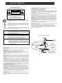
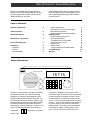
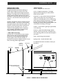
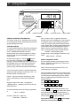
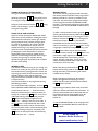
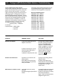
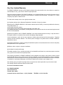
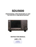
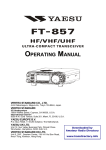
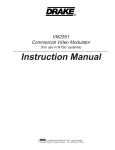
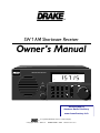
® SW1 AM Shortwave Receiver Owner's Manual SW1 Shortwave Receiver RF GAIN MEMORY MODE POWER TUNING 1 2 3 MEM RCL 4 5 6 MEM STORE 7 8 9 CLEAR 0 ENTER VOLUME Downloaded by Amateur Radio Directory www.hamdirectory.info ® is a registered trademark of the R. L. Drake Company © Copyright 1996 R. L. Drake Co. P/N3851331B-7-1996 Printed in the U. S. A. 2 Important Safeguards WARNING: TO PREVENT FIRE OR ELECTRICAL SHOCK DO NOT EXPOSE THIS PRODUCT'S AC ADAPTOR TO RAIN OR MOISTURE ¡WARNING! RISK OF ELECTRIC SHOCK DO NOT OPEN WARNING: TO REDUCE THE RISK OF ELECTRIC SHOCK, DO NOT REMOVE COVER OF AC ADAPTOR NO USER-SERVICABLE PARTS INSIDE REFER SERVICING TO QUALIFIED PERSONNEL An appliance and cart combination should be moved with care. Quick stops, excessive force and uneven surfaces may cause the appliance and cart combination to overturn. The lightning flash with arrow head symbol, within an equilateral triangle, is intended to alert the user to the presence of uninsulated "dangerous voltage" within the product's enclosure that may be of sufficient magnitude to constitute a risk of electric shock to persons. The exclamation point within an equilateral triangle is intended to alert the user to the presence of important operating and maintenance (servicing) instructions in the literature accompanying the appliance. 15. Damage Requiring Service—Unplug this product from the wall outlet and refer servicing to qualified service personnel under the following conditions: a. When the AC adaptor cord or plug is damaged. b. If the AC adaptor has been exposed to rain or water. c. If the product does not operate normally by following the operating instructions. Adjust only those controls that are covered by the operating instructions. An improper adjustment may result in damage and will often require extensive work by a qualified technician to restore the product to its normal operation. d. If the product has been dropped or the cabinet has been damaged. e. When the product exhibits a distinct change in performance—this indicates a need for service. 16. Replacement Parts—When replacement parts are required, be sure the service technician has used replacement parts specified by the manufacturer or have the same characteristics as the original parts. Unauthorized substitutes may result in fire, electric shock or other hazards. 17. Safety Check—Upon completion of any service or repairs to this product, ask the service technician to perform safety checks to determine that the product is in proper operating condition. 18. Outdoor Antenna Grounding—Before attempting to install this product, be sure the antenna or cable system is grounded so as to provide some protection against voltage surges and builtup static charges. a. Use No.10 AWG (5.3mm2) copper, No.8 AWG (8.4mm2) aluminum, No.17 AWG (1.0mm2) copper-clad steel or bronze wire or larger, as ground wire. b. Secure antenna lead-in and ground wires to house with stand-off insulators spaced from 4 feet (1.22m) to 6 feet (1.83m) apart. c. Mount antenna discharge unit as close as possible to where lead-in enters house. d. A driven rod may be used as the grounding electrode where other types of electrode systems do not exist. Refer to the National Electrical Code, ANSI/NFPA 70-1990 for information. e. Use jumper wire not smaller than No.6 AWG 13.3mm2) copper or equivalent, when a separate antenna grounding electrode is used. WARNING: TO REDUCE THE RISK OF FIRE OR ELECTRIC SHOCK, DO NOT EXPOSE THIS PRODUCT'S AC ADAPTOR TO RAIN OR MOISTURE. DO NOT OPEN THE CABINET, REFER SERVICING TO QUALIFIED PERSONNEL ONLY. CAUTION: TO PREVENT ELECTRIC SHOCK, DO NOT USE THE AC ADAPTOR WITH AN EXTENSION CORD RECEPTACLE OR OTHER OUTLET UNLESS THE BLADES OF THE AC ADAPTOR CAN BE FULLY INSERTED TO PREVENT BLADE EXPOSURE. ATTENTION: POUR PREVENIR LES CHOCS ELECTRIQUES, NE PAS UTILISER CETTE FICHE POLARISEE AVEC UN PROLONGATEUR, UNE PRISE DE COURANT OU UNE AUTRE SORTIE DE COURANT, SAUF SI LES LAMES PEUVENT ETRE INSEREES A FOND SANS EN LAISSER AUCUNE PARTIE A DECOUVERT. 1. Read Instructions—All the safety and operating instructions should be read before the appliance is operated. 2. Retain Instructions—The safety and operating instructions should be retained for future reference. 3. Heed Warnings—All warnings on the appliance should be adhered to. 4. Follow Instructions—All operating and use instructions should be followed. 5. Cleaning—Unplug this appliance from the wall outlet before cleaning. Do not use liquid cleaners or aerosol cleansers. Use a damp cloth for cleaning. 6. Do Not Use Attachments—not recommended by the manufacturer or they may cause hazards. 7. Water and Moisture—Do not use this product near water—for example, near a bathtub, wash bowl, kitchen sink, laundry tub, in a wet basement, or near a swimming pool—and the like. 8. Accessories—Do not place this product on an unstable cart, stand, tripod, bracket, or table. The product may fall, causing serious injury to a child or adult, and serious damage to the appliance. 9. Ventilation—This product should never be placed near or over a radiator or heat register. This product should not be placed in a built-in installation such as a bookcase or rack unless proper ventilation is provided or the manufacturer’s instructions have been adhered to. Any slots or openings in the cabinet are provided for ventilation. To ensure reliable operation of the product and to protect it from overheating, these openings must not be blocked or covered. The openings should never be blocked by placing the product on a bed, sofa, rug, or other similar surface. KEEP CURTAINS AND OTHER FLAMMABLE MATERIALS OUT OF DIRECT CONTACT WITH THE AC ADAPTOR. 10. Power Sources—This product should be operated only from the type of power source indicated on the marking label of the supplied AC Adaptor. If you are not sure of the type of power supplied to your home, consult your appliance dealer or local power company. 11. Lightning—For added protection for this product during a lightning storm, or when it is left unattended and unused for long periods of time, unplug the AC adaptor from the wall outlet. 12. Power Lines—An outside antenna system should not be located in the vicinity of overhead power lines, other electric light or power circuits, where it can fall into such power lines or circuits. When installing an outside antenna system, extreme care should be taken to keep from touching such power lines or circuits as contact with them may be fatal. 13. Overloading—Do not overload wall outlets and extension cords as this can result in a risk of fire or electric shock. 14. Servicing—Do not attempt to service this product yourself as opening or removing covers may expose you to dangerous voltage or other hazards. Refer all servicing to qualified service personnel. EXAMPLE OF ANTENNA GROUNDING ANTENNA LEAD IN WIRE GROUND CLAMP ANTENNA DISCHARGE UNIT (NEC SECTION 810-20) ELECTRIC SERVICE EQUIPMENT GROUNDING CONDUCTORS (NEC SECTION 810-21) GROUND CLAMPS POWER SERVICE GROUNDING ELECTRODE SYSTEM (NEC ART 250, PART H) Table of Contents / General Description 3 Please carefully read the Owner's Manual in order to take advantage of the many interesting features that will provide enjoyable listening to radio broadcasts around the world. Thank you for purchasing an SW1 AM Shortwave Receiver. This receiver has been designed and manufactured to high quality standards, and will provide reliable operation for many years. TABLE OF CONTENTS Important Safeguards 2 Table of Contents 3 General Description 3 Specifications / Accessories 4 Front Panel Description 5 Installation Unpacking Location Fixed Installation 6 6 6 6 Antenna Requirements Operation From 12 VDC Vehicle Supply Basic Antenna Connection Random Length Wire Antenna Installation Getting Started General Operating Information Direct Frequency Entry Tuning Buttons and Tuning Wheel Using the RF Gain Control Memory Store Memory Recall Tuning to AM Shortwave Radio Stations Troubleshooting Warranty 6 6 6 7 8 8 8 9 9 9 9 10 10 11 GENERAL DESCRIPTION SW1 Shortwave Receiver RF GAIN POWER MEMORY MODE TUNING 1 2 3 MEM RCL 4 5 6 MEM STORE 7 8 9 CLEAR 0 ENTER VOLUME The SW1 is a microprocessor controlled, synthesized, AM shortwave receiver with continuous coverage capability from 100 kHz through 30000 kHz which includes the AM broadcast and shortwave bands. The SW1 offers good sensitivity, selectivity, dynamic range and features that permit easy tuning of desired stations. Conveniently located front panel controls allow for rapid tuning to a particular frequency. The SW1 is easy to use. The operating frequency can be tuned via a tuning wheel, numeric entry. / tuning buttons, or by direct The RF Gain is adjustable via a front panel control. Dual antenna input terminals on the rear panel provide versatile and practical connection of either a coaxial 50 Ohm feedline or wire antenna connection to the receiver. A front panel LED display shows the receive frequency. Memory mode operation and connection to a source of AC (or DC) power are indicated by additional LEDs. The receiver can be operated from the supplied AC Adaptor which provides 12 VAC power, or from a nominal 12 VDC power source. 4 Specifications / Optional Accessory Frequency Range: Sensitivity: (10 dB S+N/N) (1000 Hz, 30% Mod) Readout Accuracy: Selectivity: IF Frequency: 1st IF: 2nd IF: Step Sizes: 100 - 30,000 kHz, AM mode only Operating Temperature: 00 to +500 C Less than 2.0 µV, typical Weight: 4.7 lbs. 2.1 Kg, (includes AC Adaptor) Size: Width: 10-7/8 (27.6 cm) Height: 4-3/8" (11.1 cm) (includes feet) Depth: 7-5/8" (19.4 cm), (including front knobs and rear panel connector) To nearest 1 kHz 5.5 kHz min. at -6 dB 45 MHz 455 kHz 1 kHz with Tuning Wheel 5 kHz with / buttons Antenna Inputs: SO-239 connector, 50 Ohms Screw terminal, 50 Ohms Headphone Jack: 1/8 inch stereo/mono type (monaural reception only) Supplied AC Adaptor Wall Transformer: Input: 120 VAC ±10%, 60 Hz, 15 Watts Output: 12 VAC at 830 mA maximum DC Power Requirements: 12 VDC nominal at 400 mA Downloaded by Amateur Radio Directory www.hamdirectory.info OPTIONAL ACCESSORY: Plastic Carrying Handle for the SW1. SW1 Shortwave Receiver RF GAIN POWER MEMORY MODE TUNING 1 VOLUME 2 3 MEM RCL MEM STORE 4 5 6 7 8 9 CLEAR 0 ENTER Front Panel Description 7 5 5 1 SW1 Shortwave Receiver RF GAIN POWER MEMORY MODE TUNING 1 2 3 MEM RCL 4 5 6 MEM STORE 7 8 9 CLEAR 0 ENTER VOLUME 6 4 1) Display - Indicates the operating frequency in kHz. The trailing decimal point indicates that either AC or DC power is applied to the receiver. Memory mode operation is indicated by the leading decimal point in the display. 3 2 - Press to turn the receiver On or Off. The frequency readout will be displayed when the receiver is on. - Press to toggle the display brightness between normal and dimmer settings. 2) Tuning (VFO) - The tuning wheel and the and buttons are the primary tuning controls of the receiver. Clockwise rotation of the dial increases frequency in 1 kHz steps and counterclockwise rotation decreases frequency in 1 kHz steps. The and buttons increment and decrement the frequency in 5 kHz steps. 3) Program Buttons 0 - 9 Numeric buttons - Permit direct entry of receive frequency in kHz from 100 to 30000 kHz. CLEAR - Press to cancel an entered frequency and restore the previously displayed frequency or to exit the memory mode. - Press after entering the desired operating frequency for immediate tuning to the entered frequency. Also, press after entering a MEMORY channel number to store the channel in a MEM STORE operation. ENTER - Press to enter the memory store mode. The MEMORY MODE LED will flash (see Item 1). MEM STORE - Press for a memory recall. The 'MEMORY MODE' LED will light (see Item 1). MEM RCL 4) VOLUME - Turn this clockwise to increase the volume setting. Turn this control counterclockwise to reduce the volume setting. 5) RF GAIN - This control adjusts the RF gain of the receiver and is normally set for the fully clockwise position. Turn the control counterclockwise, as required, to reduce the receiver gain for reception of strong signals. 6) SPEAKER - This is the opening for the internal speaker of the receiver. 7) HEADPHONE JACK - This connector accepts a 1/8" stereo/mono headphone connector. Reception is monaural only. 6 Installation UNPACKING - Carefully remove the SW1 and included AC Adaptor wall transformer from the shipping carton and examine them for evidence of damage. If any damage is noted, immediately contact the transportation company responsible for delivery or return the unit to the dealer from whom it was purchased. Keep the shipping carton and all packing material for the transportation company to inspect. The original carton and packing material should be retained for repackaging should it be necessary to return the receiver. Inspect the packing material for any accessories or printed material before storing the box. LOCATION - Location is not critical. For fixed locations, the SW1 should be operated from the AC Adaptor. Keep curtains and other flammable material away from direct contact with the AC Adaptor to avoid overheating the transformer which could result in failure or fire. ANTENNA REQUIREMENTS - Basic type Connect a single wire lead-in to the 50 Ohm screw terminal on the rear panel of the receiver. This leadin wire and antenna can simply be one end of the supplied 30 foot piece of wire. The wire can be distributed along an attic, out the window, or across the room, for example. The end that connects to the 50 Ohm screw terminal must have its insulation stripped back so that a good electrical connection is made between the wire and the screw terminal. Alternatively, a 50 Ohm coaxial cable feedline from a dipole, vertical or beam type antenna should be connected to the rear panel 50 Ohm SO-239 coaxial type antenna connector. A mating PL-259 connector on the receiver end of the coaxial cable is required, in this case. NOTE: Disconnect the AC Adaptor and antenna wire from the receiver if the unit will not be used for an extended period of time or if a weather storm containing damaging lightning is likely. PO WER INPUT ANTENNA 50 SW1 Rear Panel 50 GND +12 VDC - - OR 12 VAC 400 mA Coaxial DC Power Plug (-) Outside Metal 5.5mm O.D. Vehicle 12 VDC accessory connection Standard 12 VDC Power Plug (fused) (or approved accessory connector) ---------- -- - --------- --- FIXED INSTALLATION - After unpacking the unit, connect the antenna system to the appropriate antenna input. Connect system ground to the screw terminal marked GND. Plug the output cable of the AC Adaptor into the POWER INPUT connector on the rear panel of the receiver. Plug the AC Adaptor into a source of 120 VAC, 60 Hz power. Refer to Figure 2 for the diagram of a typical fixed installation. OPERATION FROM 12 VDC VEHICLE SUPPLY Observe proper polarity connection between the vehicle lighter or accessory socket and the coaxial DC power plug (5.5 mm O.D., 2.1 mm I.D.) which is intended for connection to the SW1 power socket. The exposed outside metal shell of the 5.5 mm power plug is the "-" (Negative) connection to the SW1 rear panel connector socket. The inside metal contact surface is the "+" (Positive) connection to the SW1 rear panel connector socket. (+) Inside Metal 2.1mm I.D. Fuse 1.0 A (Fast Blow) FIGURE 1 - PROPER WIRING POLARITY AND FUSING DIAGRAM WARNING: Stay away from power lines when you install this, or any, antenna. Make certain that the antenna cannot come in contact with power lines. LOW IMPEDANCE ANTENNA - OR - Run a wire the length of the attic. DO NOT PLACE WIRE NEAR POWER LINES. Disconnect antenna from receiver if there is a long time period between uses. SUPPLIED WIRE ANTENNA (30 FT) PL-259 CONNECTOR MADE IN U. S. A. BY ® PO WER INPUT ANTENNA 50 50 GND +12 VDC - - OR 12 VAC 400 mA SERIAL # THIS END MUST HAVE INSULATION REMOVED FIGURE 2 - BASIC ANTENNA CONNECTIONS Installation cont'd. RANDOM LENGTH WIRE ANTENNA INSTALLATION For general broadcast and shortwave listening, an outside random-length wire antenna can be used. Figure 3 shows a typical random-length wire antenna installation. The length of the wire may be from 30 to 100 feet. Attach and solder the lead-in to one end of the antenna. Connect the other end of the lead-in wire to the 50Ω screw terminal on the rear panel of your receiver. Generally, the higher the antenna is off the ground, the better the reception. You may use a tree or a pole as one support and your house as the other support. Use insulators at each end of the antenna to separate the antenna wire from the support wire. It is recommended to install a lightning arrestor on the lead-in wiring, especially if the antenna is outdoors and of lengths exceeding approximately 30 feet. * A Note About Grounding: A ground wire is not necessary for proper reception with this receiver when using the supplied 30 foot piece of wire or when using resonant length type antennas (dipole, vertical, or beam antennas). A ground wire may improve reception, however, in some cases, when using random length antennas. SOLDER LEAD-IN TO ANTENNA INSULATOR INSULATOR 7 TERMS TO KNOW Antenna - A length of bare antenna wire. Lead-in - A length of insulated wire. The length depends upon the height of your antenna and the location of your receiver. Ground Wire - If used, connect a heavy wire from the GND screw terminal on the rear panel of your receiver to a cold water pipe or to a 6- to 8-foot long piece of ground rod driven into the earth. The length of your ground wire depends upon the distance between your receiver and the grounding surface. (See "A Note About Grounding" on this page.) Insulators - Three ceramic or glass type, approximately 2-1/2 inches long. Ground rod - One 6-foot to 8-foot length, 3/8-inch diameter. NOTE: A ground rod is not needed if you use an alternate ground, such as the cold water pipe in your house. Clamp - One for the ground connection. Lightning arrester - One for the lead-in cable. For additional information on antennas, contact your local library. 50' TO 100' ANTENNA ANTENNA 50 PO WER INPUT 50 GND +12 VDC - - OR 12 VAC 400 mA ANTENNA DISCHARGE UNIT (to protect from lightning) * GROUND (if used) See "A Note About Grounding" on this page. GROUND ROD FIGURE 3 - RANDOM LENGTH WIRE ANTENNA 8 Getting Started SW1 Shortwave Receiver RF GAIN POWER MEMORY MODE TUNING 1 2 3 MEM RCL MEM STORE 4 5 6 7 8 9 CLEAR 0 ENTER VOLUME RF GAIN VOLUME NUMERIC KEYPAD POWER TUNING BUTTONS TUNING WHEEL FIGURE 4 GENERAL OPERATING INFORMATION This receiver is easy to use. Please take a few moments to read through this section and familiarize yourself with general operating information. GETTING STARTED 1. Connect the AC Adaptor to the receiver and plug the AC Adaptor into a source of nominal 120 VAC, 60 Hz power. POWER LED SHOULD LIGHT UP. 2. Make certain that an antenna connection is made to the appropriate rear panel ANTENNA connector or screw terminal. button to 3. Please refer to Figure 4. Press the turn on the SW1. The display will show the receive frequency. Set the RF GAIN control fully clockwise. Set the VOLUME control for a comfortable volume level. 4. Please refer to Figure 4. Tune to the desired frequency by using one of several methods covered below. Your communications receiver is calibrated in Kilohertz (kHz) and, accepts frequency entries only in kHz. You should be familiar with these terms: Kilohertz: Kilo means thousand. A Kilohertz is 1000 Hertz or 1000 cycles-per-second and is abbreviated kHz. Megahertz: Mega means million. A Megahertz is 1,000,000 Hertz or 1,000,000 cycles-per-second and is abbreviated MHz. Thus the relationship of these two frequency quantities is: 1 MHz = 1,000 kHz Examples: 5.875 MHz = 5875 kHz 29.660 MHz = 29660 kHz Meter: The term meter, as applied to shortwave listening, refers to the wavelength of a radio frequency. In many parts of the world, frequencies are listed in meters, for example, international shortwave stations in the 19 Meter band. European radio equipment and stations often refer to the wavelength of a station or band (in meters), rather than frequency (in MHz or kHz). To convert MHz to meters, use this formula: METERS = 300/Frequency (MHz) Example: What is the wavelength of 6120 kHz (6.120 MHz)? 300/6.120 MHz = 49 Meters DIRECT FREQUENCY ENTRY Enter the desired frequency by pressing the numeric buttons. Frequency is entered in kHz. Entries from 100 to 30000 are valid. NOTE: The receiver will prompt with 'Error' if an invalid frequency is attempted. Press the ENTER button after you have entered all of the desired numeric entries. The receiver will continue to receive the last tuned frequency until the ENTER button is pushed following an updated numeric entry. Example: 700 kHz Press 7 , 0 , 0 , ENTER * Example: 29660 kHz Press 2 , 9 , 6 , 6 , 0 , ** *Pressing ENTER causes the entered frequency to be tuned immediately. If ENTER is not pressed, the receiver will automatically tune to the entered frequency. A slight delay will occur if less than 5 digits was entered. **Do not press ENTER if 5 digits are entered. If you make an error, press CLEAR and the display will return to the previous frequency. Getting Started cont'd. TUNING BUTTONS and TUNING WHEEL Tuning to a desired frequency can also be accomplished by pressing the / Tuning buttons and/ or turning the Tuning wheel. The frequency will change in 5 kHz increments with the / Tuning buttons, and will change in 1 kHz increments when turning the Tuning wheel. USING THE RF GAIN CONTROL Maximum receiver sensitivity is obtained with the RF GAIN control set fully clockwise. Rotating the control counterclockwise reduces the receiver gain, thereby allowing reception of only relatively stronger signals. For most normal operation, the control is set fully clockwise. If signal distortion is noticed, which is possible when tuning in very strong (local) stations, rotate the control counterclockwise until the distortion just disappears and the desired station is still heard. The RF GAIN control can also be rotated counterclockwise to reduce background noise when no signal is present (during tuning, for example), but only relatively stronger signals will be heard with a reduced RF GAIN control setting. MEMORY STORE This receiver is capable of storing 32 (01 through 32) stations in its memory for easy recall. The receiver has all 32 locations factory preprogrammed to aid the user when using the receiver for the first time (refer to the MEMORY RECALL section and the SW1Factory Programmed Memory Channel List which is provided as a separate insert). Any of the 32 locations can be programmed by using the following procedure: MEM Tune to the desired station frequency. Press the STORE button (MEMORY MODE LED flashes) and the SW1 prompts the user with 'CH - -'. Press the numeric button(s) as desired to enter a memory location (01 through 32) and press the ENTER button. If an error is made while entering a memory channel, press the button and the display will again show the CLEAR prompt 'CH - -' allowing a new entry to be made. If the ENTER button is not pressed directly after a valid entry is made, the receiver will not store that entry. The Memory Store mode is exited automatically upon completion of storing a frequency successfully. The CLEAR button can also be pressed to exit the Memory Store mode at the 'CH - -' prompt. 9 MEMORY RECALL This receiver is factory programmed with 32 frequencies that are printed on the SW1 Factory Programmed Memory Channel List. This list is provided as a separate insert. Any of the factory programmed locations can be reprogrammed under the MEMORY STORE operation. If it is desired to reprogram a factory preset memory location, see the MEMORY STORE section on this page. To select a channel stored in memory, press the MEM RCL (Memory Recall) button (Memory Mode LED lights). Enter the desired number (01 to 32) using the numeric button(s) and press the ENTER button. If two digits are entered (for example - 01, 25 etc.), the receiver immediately tunes to that memory channel frequency and it is not necessary to press the ENTER button. If only a single digit is entered (for example - 1, 9 etc.), press the ENTER button and the receiver will automatically tune to that memory channel. If the ENTER button is not pressed after a single digit entry is made, the receiver will automatically tune to that memory channel anyway, but after a slight delay. If an error is made while in the Memory Recall mode, simply wait a few seconds, then make a new entry. While in the Memory Recall mode, the and buttons and the tuning wheel can be used to scroll through the memory channels starting with the last recalled memory channel. While in the Memory Recall mode, the receiver's display will toggle between displaying a memory location and the frequency of that location whenever button is pressed. the MEM RCL Upon entering the Memory Recall mode, the receiver will tune to the last used memory channel location. If a memory channel location has not been used since the last time the receiver has been plugged into an AC outlet, then the receiver will default to memory location '01'. To exit the MEMORY RECALL mode, simply press the CLEAR button (the MEMORY RECALL mode LED will no longer be lit). Downloaded by Amateur Radio Directory www.hamdirectory.info 10 Tuning to AM Shortwave Radio Stations / Troubleshooting Tuning to AM Shortwave Radio Stations There are many interesting, informative, and entertaining AM radio broadcasts from all points of the world that you can tune with this receiver. Your search might involve simply tuning around until you hear an interesting program. You might want to consult a guide listing station frequency and location. In some cases, the worldwide broadcast station may not list or announce its exact operating frequency but might instead announce the Meter Band in which it is operating or to which band it will move to improve worldwide reception at a particular time of day. To convert from Meters to Frequency: Frequency (MHz) = 300/Meters For example: Frequency (MHz) = 300/41 Meters = 7.315 MHz = 7315 kHz The following Shortwave Band Designators list with corresponding frequency ranges can be used as a reference for converting Meters to Frequencies: Shortwave Band Designators 120 METER: 2300 - 2500 kHz 90 METER: 3200 - 3400 kHz 75 METER: 3900 - 4000 kHz 60 METER: 4750 - 5060 kHz 49 METER: 5800 - 6200 kHz 41 METER: 7100 - 7600 kHz 31 METER: 9500 - 9900 kHz 25 METER: 11600 - 12100 kHz 22 METER: 13570 - 13870 kHz 19 METER: 15100 - 15800 kHz 16 METER: 17480 - 17900 kHz 13 METER: 21450 - 21850 kHz 11 METER: 25600 - 26100 kHz TROUBLESHOOTING PROBLEM PROBABLE CAUSE SOLUTION No front panel display A) No power applied either by AC Adaptor or DC source. A) Check that AC Adaptor cable or DC cable is properly connected to the rear panel POWER INPUT connector. Check that the AC Adaptor is plugged into a source of nominal 120 VAC power source. B) Check the AC Adaptor and replace if defective. Check DC power source, fuse and cable. C) Press the button for a frequency display. B) Defective AC Adaptor or blown fuse in DC power cable (if DC is the intended source). C) Receiver in the power OFF mode. Stations sound is distorted A) Receiver is not tuned onto the station properly. B) RF GAIN control set fully clockwise and receiving a very powerful, nearby radio station. A) Slowly turn the tuning wheel to clarify the sound. B) Rotate the RF GAIN control counterclockwise until the distortion just disappears or is reduced. Adjust to full gain when retuning to a weaker station. Weak stations are hard to receive A) RF GAIN control not set fully clockwise. B) Ineffective length and placement of antenna. A) Adjust RF GAIN control clockwise until weaker stations are received B) Make sure the antenna is properly connected and of effective length. Check for proper placement (height above ground, etc.). Warranty 11 One Year Limited Warranty R.L.DRAKE COMPANY warrants to the original purchaser this product shall be free from defects in material or workmanship for one (1) year from the date of original purchase. During the warranty period the R.L.DRAKE COMPANY or an authorized Drake service facility will provide, free of charge, both parts and labor necessary to correct defects in material and workmanship. At its option, R. L. Drake Company may replace a defective unit. To obtain such warranty service, the original purchaser must: (1) Complete and send in the Warranty Registration Card within 10 days of purchase. (2) Notify the R.L.DRAKE COMPANY or the nearest authorized service facility, as soon as possible after discovery of a possible defect, of: (a) the model and serial number, (b) the identity of the seller and the approximate date of purchase; and (c) A detailed description of the problem, including details on the electrical connection to associated equipment and the list of such equipment. (3) Deliver the product to the R.L.DRAKE COMPANY or the nearest authorized service facility, or ship the same in its original container or equivalent, fully insured and shipping charges prepaid. Correct maintenance, repair, and use are important to obtain proper performance from this product. Therefore carefully read the Instruction Manual. This warranty does not apply to any defect that R.L.DRAKE COMPANY determines is due to: (1) Improper maintenance or repair, including the installation of parts or accessories that do not conform to the quality and specifications of the original parts. (2) Misuse, abuse, neglect or improper installation. (3) Accidental or intentional damage. All implied warranties, if any, including warranties of merchantability and fitness for a particular purpose, terminate one (1) year from the date of the original purchase. The foregoing constitutes R.L.DRAKE COMPANY’S entire obligation with respect to this product, and the original purchaser shall have no other remedy and no claim for incidental or consequential damages, losses or expenses. Some states do not allow limitations on how long an implied warranty lasts or do not allow the exclusions or limitation of incidental or consequential damages, so the above limitation and exclusion may not apply to you. This warranty gives you specific legal right and you may also have other rights which vary from state to state. This warranty shall be construed under the laws of Ohio. For service information contact: R.L. DRAKE COMPANY 230 Industrial Drive Franklin, Ohio 45005 Customer Service Center Phone: +1 (513) 746-6990 TELEFAX: +1 (513) 743-4576 ® R.L. DRAKE COMPANY 230 INDUSTRIAL DRIVE FRANKLIN, OHIO 45005 U. S .A. CUSTOMER SERVICE AND PARTS TELEPHONE: +1 (513) 746-6990 TELEFAX: +1 (513) 743-4576 Downloaded by Amateur Radio Directory www.hamdirectory.info