1
INSTALLATION AND
OPERATION MANUAL
MiRICi-E3T3
Intelligent Miniature Ethernet to E3/T3
Remote Bridge
Version 2.2
The Access Company
MiRICi-E3T3
Intelligent Miniature Ethernet to E3/T3 Remote Bridge
Version 2.2
Installation and Operation Manual
Notice
This manual contains information that is proprietary to RAD Data Communications Ltd. ("RAD").
No part of this publication may be reproduced in any form whatsoever without prior written
approval by RAD Data Communications.
Right, title and interest, all information, copyrights, patents, know-how, trade secrets and other
intellectual property or other proprietary rights relating to this manual and to the MiRICi-E3T3
and any software components contained therein are proprietary products of RAD protected
under international copyright law and shall be and remain solely with RAD.
The MiRICi-E3T3 product name is owned by RAD. No right, license, or interest to such trademark
is granted hereunder, and you agree that no such right, license, or interest shall be asserted by
you with respect to such trademark. The RAD name, logo, logotype, and the terms EtherAccess,
TDMoIP and TDMoIP Driven, and the product names Optimux and IPmux, are registered
trademarks of RAD Data Communications Ltd. All other trademarks are the property of their
respective holders.
You shall not copy, reverse compile or reverse assemble all or any portion of the Manual or the
MiRICi-E3T3. You are prohibited from, and shall not, directly or indirectly, develop, market,
distribute, license, or sell any product that supports substantially similar functionality as the
MiRICi-E3T3, based on or derived in any way from the MiRICi-E3T3. Your undertaking in this
paragraph shall survive the termination of this Agreement.
This Agreement is effective upon your opening of the MiRICi-E3T3 package and shall continue
until terminated. RAD may terminate this Agreement upon the breach by you of any term hereof.
Upon such termination by RAD, you agree to return to RAD the MiRICi-E3T3 and all copies and
portions thereof.
For further information contact RAD at the address below or contact your local distributor.
International Headquarters
RAD Data Communications Ltd.
North America Headquarters
RAD Data Communications Inc.
24 Raoul Wallenberg Street
Tel Aviv 69719, Israel
Tel: 972-3-6458181
Fax: 972-3-6498250, 6474436
E-mail: [email protected]
900 Corporate Drive
Mahwah, NJ 07430, USA
Tel: (201) 5291100, Toll free: 1-800-4447234
Fax: (201) 5295777
E-mail: [email protected]
© 2007–2009 RAD Data Communications Ltd.
Publication No. 513-200-02/09
Limited Warranty
RAD warrants to DISTRIBUTOR that the hardware in the MiRICi-E3T3 to be delivered hereunder
shall be free of defects in material and workmanship under normal use and service for a period
of twelve (12) months following the date of shipment to DISTRIBUTOR.
If, during the warranty period, any component part of the equipment becomes defective by
reason of material or workmanship, and DISTRIBUTOR immediately notifies RAD of such defect,
RAD shall have the option to choose the appropriate corrective action: a) supply a replacement
part, or b) request return of equipment to its plant for repair, or c) perform necessary repair at
the equipment's location. In the event that RAD requests the return of equipment, each party
shall pay one-way shipping costs.
RAD shall be released from all obligations under its warranty in the event that the equipment has
been subjected to misuse, neglect, accident or improper installation, or if repairs or
modifications were made by persons other than RAD's own authorized service personnel, unless
such repairs by others were made with the written consent of RAD.
The above warranty is in lieu of all other warranties, expressed or implied. There are no
warranties which extend beyond the face hereof, including, but not limited to, warranties of
merchantability and fitness for a particular purpose, and in no event shall RAD be liable for
consequential damages.
RAD shall not be liable to any person for any special or indirect damages, including, but not
limited to, lost profits from any cause whatsoever arising from or in any way connected with the
manufacture, sale, handling, repair, maintenance or use of the MiRICi-E3T3, and in no event shall
RAD's liability exceed the purchase price of the MiRICi-E3T3.
DISTRIBUTOR shall be responsible to its customers for any and all warranties which it makes
relating to MiRICi-E3T3 and for ensuring that replacements and other adjustments required in
connection with the said warranties are satisfactory.
Software components in the MiRICi-E3T3 are provided "as is" and without warranty of any kind.
RAD disclaims all warranties including the implied warranties of merchantability and fitness for a
particular purpose. RAD shall not be liable for any loss of use, interruption of business or
indirect, special, incidental or consequential damages of any kind. In spite of the above RAD
shall do its best to provide error-free software products and shall offer free Software updates
during the warranty period under this Agreement.
RAD's cumulative liability to you or any other party for any loss or damages resulting from any
claims, demands, or actions arising out of or relating to this Agreement and the MiRICi-E3T3 shall
not exceed the sum paid to RAD for the purchase of the MiRICi-E3T3. In no event shall RAD be
liable for any indirect, incidental, consequential, special, or exemplary damages or lost profits,
even if RAD has been advised of the possibility of such damages.
This Agreement shall be construed and governed in accordance with the laws of the State of
Israel.
Product Disposal
To facilitate the reuse, recycling and other forms of recovery of waste
equipment in protecting the environment, the owner of this RAD product is
required to refrain from disposing of this product as unsorted municipal
waste at the end of its life cycle. Upon termination of the unit’s use,
customers should provide for its collection for reuse, recycling or other form
of environmentally conscientious disposal.
General Safety Instructions
The following instructions serve as a general guide for the safe installation and operation of
telecommunications products. Additional instructions, if applicable, are included inside the
manual.
Safety Symbols
This symbol may appear on the equipment or in the text. It indicates potential
safety hazards regarding product operation or maintenance to operator or service
personnel.
Warning
Danger of electric shock! Avoid any contact with the marked surface while the
product is energized or connected to outdoor telecommunication lines.
Protective ground: the marked lug or terminal should be connected to the building
protective ground bus.
Warning
Some products may be equipped with a laser diode. In such cases, a label with the
laser class and other warnings as applicable will be attached near the optical
transmitter. The laser warning symbol may be also attached.
Please observe the following precautions:
•
Before turning on the equipment, make sure that the fiber optic cable is intact
and is connected to the transmitter.
•
Do not attempt to adjust the laser drive current.
•
Do not use broken or unterminated fiber-optic cables/connectors or look
straight at the laser beam.
•
The use of optical devices with the equipment will increase eye hazard.
•
Use of controls, adjustments or performing procedures other than those
specified herein, may result in hazardous radiation exposure.
ATTENTION: The laser beam may be invisible!
In some cases, the users may insert their own SFP laser transceivers into the product. Users are
alerted that RAD cannot be held responsible for any damage that may result if non-compliant
transceivers are used. In particular, users are warned to use only agency approved products that
comply with the local laser safety regulations for Class 1 laser products.
Always observe standard safety precautions during installation, operation and maintenance of
this product. Only qualified and authorized service personnel should carry out adjustment,
maintenance or repairs to this product. No installation, adjustment, maintenance or repairs
should be performed by either the operator or the user.
Handling Energized Products
General Safety Practices
Do not touch or tamper with the power supply when the power cord is connected. Line voltages
may be present inside certain products even when the power switch (if installed) is in the OFF
position or a fuse is blown. For DC-powered products, although the voltages levels are usually
not hazardous, energy hazards may still exist.
Before working on equipment connected to power lines or telecommunication lines, remove
jewelry or any other metallic object that may come into contact with energized parts.
Unless otherwise specified, all products are intended to be grounded during normal use.
Grounding is provided by connecting the mains plug to a wall socket with a protective ground
terminal. If a ground lug is provided on the product, it should be connected to the protective
ground at all times, by a wire with a diameter of 18 AWG or wider. Rack-mounted equipment
should be mounted only in grounded racks and cabinets.
Always make the ground connection first and disconnect it last. Do not connect
telecommunication cables to ungrounded equipment. Make sure that all other cables are
disconnected before disconnecting the ground.
Some products may have panels secured by thumbscrews with a slotted head. These panels may
cover hazardous circuits or parts, such as power supplies. These thumbscrews should therefore
always be tightened securely with a screwdriver after both initial installation and subsequent
access to the panels.
Connecting AC Mains
Make sure that the electrical installation complies with local codes.
Always connect the AC plug to a wall socket with a protective ground.
The maximum permissible current capability of the branch distribution circuit that supplies power
to the product is 16A. The circuit breaker in the building installation should have high breaking
capacity and must operate at short-circuit current exceeding 35A.
Always connect the power cord first to the equipment and then to the wall socket. If a power
switch is provided in the equipment, set it to the OFF position. If the power cord cannot be
readily disconnected in case of emergency, make sure that a readily accessible circuit breaker or
emergency switch is installed in the building installation.
In cases when the power distribution system is IT type, the switch must disconnect both poles
simultaneously.
Connecting DC Power
Unless otherwise specified in the manual, the DC input to the equipment is floating in reference
to the ground. Any single pole can be externally grounded.
Due to the high current capability of DC power systems, care should be taken when connecting
the DC supply to avoid short-circuits and fire hazards.
DC units should be installed in a restricted access area, i.e. an area where access is authorized
only to qualified service and maintenance personnel.
Make sure that the DC power supply is electrically isolated from any AC source and that the
installation complies with the local codes.
The maximum permissible current capability of the branch distribution circuit that supplies power
to the product is 16A. The circuit breaker in the building installation should have high breaking
capacity and must operate at short-circuit current exceeding 35A.
Before connecting the DC supply wires, ensure that power is removed from the DC circuit. Locate
the circuit breaker of the panel board that services the equipment and switch it to the OFF
position. When connecting the DC supply wires, first connect the ground wire to the
corresponding terminal, then the positive pole and last the negative pole. Switch the circuit
breaker back to the ON position.
A readily accessible disconnect device that is suitably rated and approved should be incorporated
in the building installation.
If the DC power supply is floating, the switch must disconnect both poles simultaneously.
Connecting Data and Telecommunications Cables
Data and telecommunication interfaces are classified according to their safety status.
The following table lists the status of several standard interfaces. If the status of a given port
differs from the standard one, a notice will be given in the manual.
Ports
Safety Status
V.11, V.28, V.35, V.36, RS-530, X.21,
10 BaseT, 100 BaseT, Unbalanced E1,
E2, E3, STM, DS-2, DS-3, S-Interface
ISDN, Analog voice E&M
SELV
xDSL (without feeding voltage),
Balanced E1, T1, Sub E1/T1
TNV-1 Telecommunication Network Voltage-1:
FXS (Foreign Exchange Subscriber)
TNV-2 Telecommunication Network Voltage-2:
Ports whose normal operating voltage exceeds the
limits of SELV (usually up to 120 VDC or telephone
ringing voltages), on which overvoltages from
telecommunication networks are not possible. These
ports are not permitted to be directly connected to
external telephone and data lines.
FXO (Foreign Exchange Office), xDSL
(with feeding voltage), U-Interface
ISDN
TNV-3 Telecommunication Network Voltage-3:
Ports whose normal operating voltage exceeds the
limits of SELV (usually up to 120 VDC or telephone
ringing voltages), on which overvoltages from
telecommunication networks are possible.
Safety Extra Low Voltage:
Ports which do not present a safety hazard. Usually
up to 30 VAC or 60 VDC.
Ports whose normal operating voltage is within the
limits of SELV, on which overvoltages from
telecommunications networks are possible.
Always connect a given port to a port of the same safety status. If in doubt, seek the assistance
of a qualified safety engineer.
Always make sure that the equipment is grounded before connecting telecommunication cables.
Do not disconnect the ground connection before disconnecting all telecommunications cables.
Some SELV and non-SELV circuits use the same connectors. Use caution when connecting cables.
Extra caution should be exercised during thunderstorms.
When using shielded or coaxial cables, verify that there is a good ground connection at both
ends. The grounding and bonding of the ground connections should comply with the local codes.
The telecommunication wiring in the building may be damaged or present a fire hazard in case of
contact between exposed external wires and the AC power lines. In order to reduce the risk,
there are restrictions on the diameter of wires in the telecom cables, between the equipment
and the mating connectors.
Caution
To reduce the risk of fire, use only No. 26 AWG or larger telecommunication line
cords.
Attention
Pour réduire les risques s’incendie, utiliser seulement des conducteurs de
télécommunications 26 AWG ou de section supérieure.
Some ports are suitable for connection to intra-building or non-exposed wiring or cabling only. In
such cases, a notice will be given in the installation instructions.
Do not attempt to tamper with any carrier-provided equipment or connection hardware.
Electromagnetic Compatibility (EMC)
The equipment is designed and approved to comply with the electromagnetic regulations of
major regulatory bodies. The following instructions may enhance the performance of the
equipment and will provide better protection against excessive emission and better immunity
against disturbances.
A good ground connection is essential. When installing the equipment in a rack, make sure to
remove all traces of paint from the mounting points. Use suitable lock-washers and torque. If an
external grounding lug is provided, connect it to the ground bus using braided wire as short as
possible.
The equipment is designed to comply with EMC requirements when connecting it with unshielded
twisted pair (UTP) cables. However, the use of shielded wires is always recommended, especially
for high-rate data. In some cases, when unshielded wires are used, ferrite cores should be
installed on certain cables. In such cases, special instructions are provided in the manual.
Disconnect all wires which are not in permanent use, such as cables used for one-time
configuration.
The compliance of the equipment with the regulations for conducted emission on the data lines
is dependent on the cable quality. The emission is tested for UTP with 80 dB longitudinal
conversion loss (LCL).
Unless otherwise specified or described in the manual, TNV-1 and TNV-3 ports provide secondary
protection against surges on the data lines. Primary protectors should be provided in the building
installation.
The equipment is designed to provide adequate protection against electro-static discharge (ESD).
However, it is good working practice to use caution when connecting cables terminated with
plastic connectors (without a grounded metal hood, such as flat cables) to sensitive data lines.
Before connecting such cables, discharge yourself by touching ground or wear an ESD preventive
wrist strap.
FCC-15 User Information
This equipment has been tested and found to comply with the limits of the Class A digital device,
pursuant to Part 15 of the FCC rules. These limits are designed to provide reasonable protection
against harmful interference when the equipment is operated in a commercial environment. This
equipment generates, uses and can radiate radio frequency energy and, if not installed and used
in accordance with the Installation and Operation manual, may cause harmful interference to the
radio communications. Operation of this equipment in a residential area is likely to cause harmful
interference in which case the user will be required to correct the interference at his own
expense.
Canadian Emission Requirements
This Class A digital apparatus meets all the requirements of the Canadian Interference-Causing
Equipment Regulation.
Cet appareil numérique de la classe A respecte toutes les exigences du Règlement sur le matériel
brouilleur du Canada.
Warning per EN 55022 (CISPR-22)
Warning
Avertissement
Achtung
This is a class A product. In a domestic environment, this product may cause radio
interference, in which case the user will be required to take adequate measures.
Cet appareil est un appareil de Classe A. Dans un environnement résidentiel, cet
appareil peut provoquer des brouillages radioélectriques. Dans ces cas, il peut être
demandé à l’utilisateur de prendre les mesures appropriées.
Das vorliegende Gerät fällt unter die Funkstörgrenzwertklasse A. In Wohngebieten
können beim Betrieb dieses Gerätes Rundfunkströrungen auftreten, für deren
Behebung der Benutzer verantwortlich ist.
Français
Mise au rebut du produit
Afin de faciliter la réutilisation, le recyclage ainsi que d'autres formes de
récupération d'équipement mis au rebut dans le cadre de la protection de
l'environnement, il est demandé au propriétaire de ce produit RAD de ne pas
mettre ce dernier au rebut en tant que déchet municipal non trié, une fois
que le produit est arrivé en fin de cycle de vie. Le client devrait proposer des
solutions de réutilisation, de recyclage ou toute autre forme de mise au rebut
de cette unité dans un esprit de protection de l'environnement, lorsqu'il aura
fini de l'utiliser.
Instructions générales de sécurité
Les instructions suivantes servent de guide général d'installation et d'opération sécurisées des
produits de télécommunications. Des instructions supplémentaires sont éventuellement
indiquées dans le manuel.
Symboles de sécurité
Ce symbole peut apparaitre sur l'équipement ou dans le texte. Il indique des risques
potentiels de sécurité pour l'opérateur ou le personnel de service, quant à
l'opération du produit ou à sa maintenance.
Avertissement
Danger de choc électrique ! Evitez tout contact avec la surface marquée tant que le
produit est sous tension ou connecté à des lignes externes de télécommunications.
Mise à la terre de protection : la cosse ou la borne marquée devrait être connectée
à la prise de terre de protection du bâtiment.
•
Avant la mise en marche de l'équipement, assurez-vous que le câble de fibre
optique est intact et qu'il est connecté au transmetteur.
•
Ne tentez pas d'ajuster le courant de la commande laser.
•
N'utilisez pas des câbles ou connecteurs de fibre optique cassés ou sans
terminaison et n'observez pas directement un rayon laser.
•
L'usage de périphériques optiques avec l'équipement augmentera le risque pour
les yeux.
•
L'usage de contrôles, ajustages ou procédures autres que celles spécifiées ici
pourrait résulter en une dangereuse exposition aux radiations.
ATTENTION : Le rayon laser peut être invisible !
Les utilisateurs pourront, dans certains cas, insérer leurs propres émetteurs-récepteurs Laser SFP
dans le produit. Les utilisateurs sont avertis que RAD ne pourra pas être tenue responsable de
tout dommage pouvant résulter de l'utilisation d'émetteurs-récepteurs non conformes. Plus
particulièrement, les utilisateurs sont avertis de n'utiliser que des produits approuvés par
l'agence et conformes à la réglementation locale de sécurité laser pour les produits laser de
classe 1.
Respectez toujours les précautions standards de sécurité durant l'installation, l'opération et la
maintenance de ce produit. Seul le personnel de service qualifié et autorisé devrait effectuer
l'ajustage, la maintenance ou les réparations de ce produit. Aucune opération d'installation,
d'ajustage, de maintenance ou de réparation ne devrait être effectuée par l'opérateur ou
l'utilisateur.
Manipuler des produits sous tension
Règles générales de sécurité
Ne pas toucher ou altérer l'alimentation en courant lorsque le câble d'alimentation est branché.
Des tensions de lignes peuvent être présentes dans certains produits, même lorsque le
commutateur (s'il est installé) est en position OFF ou si le fusible est rompu. Pour les produits
alimentés par CC, les niveaux de tension ne sont généralement pas dangereux mais des risques
de courant peuvent toujours exister.
Avant de travailler sur un équipement connecté aux lignes de tension ou de télécommunications,
retirez vos bijoux ou tout autre objet métallique pouvant venir en contact avec les pièces sous
tension.
Sauf s'il en est autrement indiqué, tous les produits sont destinés à être mis à la terre durant
l'usage normal. La mise à la terre est fournie par la connexion de la fiche principale à une prise
murale équipée d'une borne protectrice de mise à la terre. Si une cosse de mise à la terre est
fournie avec le produit, elle devrait être connectée à tout moment à une mise à la terre de
protection par un conducteur de diamètre 18 AWG ou plus. L'équipement monté en châssis ne
devrait être monté que sur des châssis et dans des armoires mises à la terre.
Branchez toujours la mise à la terre en premier et débranchez-la en dernier. Ne branchez pas des
câbles de télécommunications à un équipement qui n'est pas mis à la terre. Assurez-vous que
tous les autres câbles sont débranchés avant de déconnecter la mise à la terre.
Français
Certains produits peuvent être équipés d'une diode laser. Dans de tels cas, une
étiquette indiquant la classe laser ainsi que d'autres avertissements, le cas échéant,
sera jointe près du transmetteur optique. Le symbole d'avertissement laser peut
aussi être joint.
Avertissement
Veuillez observer les précautions suivantes :
Français
Connexion au courant du secteur
Assurez-vous que l'installation électrique est conforme à la réglementation locale.
Branchez toujours la fiche de secteur à une prise murale équipée d'une borne protectrice de mise
à la terre.
La capacité maximale permissible en courant du circuit de distribution de la connexion alimentant
le produit est de 16A. Le coupe-circuit dans l'installation du bâtiment devrait avoir une capacité
élevée de rupture et devrait fonctionner sur courant de court-circuit dépassant 35A.
Branchez toujours le câble d'alimentation en premier à l'équipement puis à la prise murale. Si un
commutateur est fourni avec l'équipement, fixez-le en position OFF. Si le câble d'alimentation ne
peut pas être facilement débranché en cas d'urgence, assurez-vous qu'un coupe-circuit ou un
disjoncteur d'urgence facilement accessible est installé dans l'installation du bâtiment.
Le disjoncteur devrait déconnecter simultanément les deux pôles si le système de distribution de
courant est de type IT.
Connexion d'alimentation CC
Sauf s'il en est autrement spécifié dans le manuel, l'entrée CC de l'équipement est flottante par
rapport à la mise à la terre. Tout pôle doit être mis à la terre en externe.
A cause de la capacité de courant des systèmes à alimentation CC, des précautions devraient
être prises lors de la connexion de l'alimentation CC pour éviter des courts-circuits et des risques
d'incendie.
Les unités CC devraient être installées dans une zone à accès restreint, une zone où l'accès n'est
autorisé qu'au personnel qualifié de service et de maintenance.
Assurez-vous que l'alimentation CC est isolée de toute source de courant CA (secteur) et que
l'installation est conforme à la réglementation locale.
La capacité maximale permissible en courant du circuit de distribution de la connexion alimentant
le produit est de 16A. Le coupe-circuit dans l'installation du bâtiment devrait avoir une capacité
élevée de rupture et devrait fonctionner sur courant de court-circuit dépassant 35A.
Avant la connexion des câbles d'alimentation en courant CC, assurez-vous que le circuit CC n'est
pas sous tension. Localisez le coupe-circuit dans le tableau desservant l'équipement et fixez-le
en position OFF. Lors de la connexion de câbles d'alimentation CC, connectez d'abord le
conducteur de mise à la terre à la borne correspondante, puis le pôle positif et en dernier, le
pôle négatif. Remettez le coupe-circuit en position ON.
Un disjoncteur facilement accessible, adapté et approuvé devrait être intégré à l'installation du
bâtiment.
Le disjoncteur devrait déconnecter simultanément les deux pôles si l'alimentation en courant CC
est flottante.
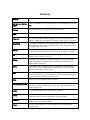
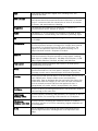
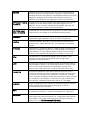
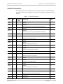
Glossary
Address
A coded representation of the origin or destination of data.
AIS (Alarm Indication
Signal)
One of the OAM function types used for fault management (see also
CC).
Analog
A continuous wave or signal (such as human voice).
AWG
The American Wire Gauge System, which specifies wire width.
Balanced
A transmission line in which voltages on the two conductors are
equal in magnitude, but opposite in polarity, with respect to ground.
Bandwidth
The range of frequencies passing through a given circuit. The greater
the bandwidth, the more information can be sent through the circuit
in a given amount of time.
Bipolar
Signaling method in E3/T3 representing a binary “1” by alternating
positive and negative pulses, and a binary “0” by absence of pulses.
Bit
The smallest unit of information in a binary system. Represents
either a one or zero (“1” or “0”).
Bridge
A device interconnecting local area networks at the OSI data link
layer, filtering and forwarding frames according to media access
control (MAC) addresses.
Buffer
A storage device. Commonly used to compensate for differences in
data rates or event timing when transmitting from one device to
another. Also used to remove jitter.
Bus
A transmission path or channel. A bus is typically an electrical
connection with one or more conductors, where all attached devices
receive all transmissions at the same time.
Byte
A group of bits (normally 8 bits in length).
CC (Continuity Check)
A frame used periodically to check whether a connection is idle or
has failed. Continuity checking is one of the OAM function types for
fault management.
cHDLC
A Cisco proprietary version of the HDLC protocol.
Carrier
A continuous signal at a fixed frequency that is capable of being
modulated with a second (information carrying) signal.
Channel
A path for electrical transmission between two or more points. Also
called a link, line, circuit or facility.
Clock
A term for the source(s) of timing signals used in synchronous
transmission.
Data
Information represented in digital form, including voice, text,
facsimile and video.
Data Link Layer
Layer 2 of the OSI model. The entity, which establishes, maintains,
and releases data-link connections between elements in a network.
Layer 2 is concerned with the transmission of units of information,
or frames, and associated error checking.
Diagnostics
The detection and isolation of a malfunction or mistake in a
communications device, network or system.
Digital
The binary (“1” or “0”) output of a computer or terminal. In data
communications, an alternating, non-continuous (pulsating) signal.
E3
The European standard for high speed digital transmission, operating
at 34 Mbps.
Encapsulation
Encapsulating data is a technique used by layered protocols in which
a low level protocol accepts a message from a higher level protocol,
then places it in the data portion of the lower-level frame. The
logistics of encapsulation require that packets traveling over a
physical network contain a sequence of headers.
Ethernet
A local area network (LAN) technology which has extended into the
wide area networks. Ethernet operates at many speeds, including
data rates of 10 Mbps (Ethernet), 100 Mbps (Fast Ethernet), 1,000
Mbps (Gigabit Ethernet), 10 Gbps, 40 Gbps, and 100 Gbps.
Flow Control
A congestion control mechanism that results in an ATM system
implementing flow control.
Frame
A logical grouping of information sent as a link-layer unit over a
transmission medium. The terms packet, datagram, segment, and
message are also used to describe logical information groupings.
Framing
At the physical and data link layers of the OSI model, bits are fit into
units called frames. Frames contain source and destination
information, flags to designate the start and end of the frame, plus
information about the integrity of the frame. All other information,
such as network protocols and the actual payload of data, is
encapsulated in a packet, which is encapsulated in the frame.
Full Duplex
A circuit or device permitting transmission in two directions (sending
and receiving) at the same time.
FXO (Foreign
Exchange Office)
A voice interface, emulating a PBX extension, as it appears to the CO
(Central Office) for connecting a PBX extension to a multiplexer.
FXS (Foreign
Exchange Subscriber)
A voice interface, emulating the extension interface of a PBX (or
subscriber interface of a CO) for connecting a regular telephone set
to a multiplexer.
G.703
An ITU standard for the physical and electrical characteristics of
various digital interfaces, including those at 64 kbps and 2.048
Mbps.
Gateway
Gateways are points of entrance and exit from a communications
network. Viewed as a physical entity, a gateway is that node that
translates between two otherwise incompatible networks or network
segments. Gateways perform code and protocol conversion to
facilitate traffic between data highways of differing architecture.
GFP (Generic Framing
Procedure)
Defined by ITU-T G.7041, generic framing procedure allows efficient
mapping of variable length, higher-layer client signals, such as
Ethernet, over a transport network like SDH/SONET. Recently, GFP
has been extended to lower speed PDH networks.
HDLC (High-Level
Data Link Control)
A synchronous, bit-oriented link layer protocol for data transmission.
Frame Relay is an example of an HDLCbased packet protocol.
Impedance
The combined effect of resistance, inductance and capacitance on a
transmitted signal. Impedance varies at different frequencies.
Interface
A shared boundary, defined by common physical interconnection
characteristics, signal characteristics, and meanings of exchanged
signals.
IP Address
Also known as an Internet address. A unique string of numbers that
identifies a computer or device on a TCP/IP network. The format of
an IP address is a 32-bit numeric address written as four numbers
from 0 to 255, separated by periods (for example, 1.0.255.123).
Jitter
The deviation of a transmission signal in time or phase. It can
introduce errors and loss of synchronization in high speed
synchronous communications.
Laser
A device that transmits an extremely narrow and coherent beam of
electromagnetic energy in the visible light spectrum. Used as a light
source for fiber optic transmission (generally more expensive,
shorter lived, single mode only, for greater distances than LED).
Leased Line
A permanent telephone connection between two points that is
rented for exclusive use from a telecommunications common carrier.
In contrast to a normal dial-up connection, a leased line is always
active. Typically, the highest speed data connections require a leased
line connection. For example, a T1 channel is a type of leased line
that provides a maximum transmission speed of 1.544 Mbps.
Loopback
A type of diagnostic test in which the transmitted signal is returned
to the sending device after passing through all or part of a
communications link or network.
Mark
In telecommunications, this means the presence of a signal. A mark
is equivalent to a binary 1. A mark is the opposite of a space (0).
Multiplexer
At one end of a communications link, a device that combines several
lower speed transmission channels into a single high speed channel.
A multiplexer at the other end reverses the process. Sometimes
called a mux. See Bit Interleaving/Multiplexing.
Network
(1) An interconnected group of nodes. (2) A series of points, nodes,
or stations connected by communications channels; the collection of
equipment through which connections are made between data
stations.
Node
A point of interconnection to a network.
Packet
An ordered group of data and control signals transmitted through a
network, as a subset of a larger message.
parameters
Parameters are often called arguments, and the two words are used
interchangeably. However, some computer languages such as C
define argument to mean actual parameter (i.e., the value), and
parameter to mean formal parameter. In RAD CLI, parameter means
formal parameter, not value.
Payload
The 48-byte segment of the ATM cell containing user data. Any
adaptation of user data via the AAL will take place within the
payload.
Physical Layer
Layer 1 of the OSI model. The layer concerned with electrical,
mechanical, and handshaking procedures over the interface
connecting a device to the transmission medium.
Port
The physical interface to a computer or multiplexer, for connection
of terminals and modems.
Protocol
A formal set of conventions governing the formatting and relative
timing of message exchange between two communicating systems.
SFP (Small Formfactor Pluggable)
A compact optical transceiver used in optical communications. It
interfaces a network device (a switch, router or similar device) to a
fiber optic or unshielded twisted pair networking cable. It is a
popular industry format.
Single Mode
Describing an optical wave-guide or fiber that is designed to
propagate light of only a single wavelength (typically 5-10 microns in
diameter).
Space
In telecommunications, the absence of a signal. Equivalent to a
binary 0.
Synchronous
Transmission
Transmission in which data bits are sent at a fixed rate, with the
transmitter and receiver synchronized.
T1
A digital transmission link with a capacity of 1.544 Mbps used in
North America. Typically channelized into 24 DS0s, each capable of
carrying a single voice conversation or data stream. Uses two pairs
of twisted pair wires.
T3
A digital transmission link with a capacity of 45 Mbps, or 28 T1 lines.
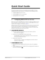
Quick Start Guide
This quick start guide instructs you on getting started with MiRICi-E3T3 and
upgrading software when necessary. It is divided into the following sections:
•
Configuring MiRICi-E3T3 for first use
•
Connecting MiRICi-E3T3 to a host device
•
Replacing MiRICi-E3T3’s software.
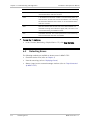
1.
Configuring MiRICi-E3T3 for First Use
Before you can start using MiRICi-E3T3, you have to assign an IP address to the
device and specify a mode of operation. To do so, connect MiRICi-E3T3 to a PC
via RAD’s SFP-CA adaptor as illustrated in Figure 2.
When you connect SFP-CA to a specific PC for the first time, you have to install
the SFP-CA driver on that PC, and configure the PC network parameters for
communication with SFP-CA. The driver installation requires a PC that has the
Windows XP operating system with Service Pack 2.
³
To install the SFP-CA driver on a PC:
1. Insert the Technical Documentation CD into the CD drive of the PC.
The CD main menu appears.
2. Click the link to the MiRIC/MiRICi Family product page.
The MiRIC/MiRICi Family product page appears, with an entry for the
SFP-CA documentation and driver.
3. Click the SFP-CA driver link.
The SFP-CA driver is installed in the background. No further action is
required to install the driver.
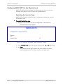
³
To connect MiRICi-E3T3 to a PC:
1. Ensure that you have installed the SFP-CA driver on the PC as explained
above.
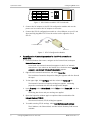
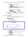
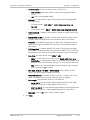
2. Enable Configuration mode for MiRICi-E3T3 by setting both DIP switches on
the device’s underside to ON.
MiRICi-E3T3 Ver. 2.2
Configuring MiRICi-E3T3 for First Use
1
Quick Start Guide
Configuring MiRICi-E3T3
SW2
SW2
SW1
State
OFF
OFF
ON
ON
OFF
ON
OFF
ON
INIT DB
Normal
SW Dwnld
Config
OFF
ON
SW1
Figure 1. DIP Switches on MiRICi-E3T3’s Underside
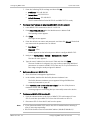
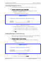
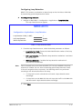
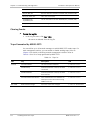
3. Connect the DC adapter to the SFP-CA configuration module and use the
power cord to connect the DC adapter to the mains.
4. Connect the SFP-CA configuration module to a free USB port on your PC and
then carefully plug MiRICi-E3T3 into the socket on the opposite side of
SFP-CA.
To the DC
Adapter
To a USB Port on a PC
MiRICi-E3T3
Figure 2. SFP-CA Configuration Module
³
To configure the PC network parameters for the SFP-CA connection to
MiRICi-E3T3:
1. From the Windows Start menu, navigate to the Control Panel, and open
Network Connections.
A new local area network connection appears in the list of network
connections. If you switch to the Details view, the device name ADMTEK
ADM8511 USB TO FAST ETHERNET CONVERTER appears.
2. Right-click this network connection, and select Properties.
The Local Area Connection Properties dialog box appears with the General
tab open.
3. To the upper right, click Configure and then select the Advanced tab.
The Network Connection Properties dialog box appears, containing
properties associated with the USB configuration adapter.
4. Under Property, select Select Media. Under Value, select Home LAN, and then
click OK.
The dialog box closes and your settings are applied.
5. Open the Properties window again as explained above and double-click
Internet Protocol (TCP/IP).
The Internet Protocol (TCP/IP) dialog box appears.
6. To enable entering TCP/IP settings, select Use the following IP Address.
The IP Address, the Subnet Mask, and the Default Gateway field become
available.
2
Configuring MiRICi-E3T3 for First Use
MiRICi-E3T3 Ver. 2.2
Configuring MiRICi-E3T3
Quick Start Guide
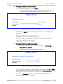
7. Enter the following TCP/IP settings and then click OK:
IP Address: 192.168.205.20
Subnet Mask: 255.255.255.0
Default Gateway: 192.168.205.1
The PC communication link with SFP-CA and MiRICi-E3T3 is ready.
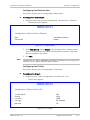
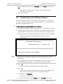
³
To change the IP address to integrate MiRICi-E3T3 into the network:
1. Leave MiRICi-E3T3 connected to the PC via SFP-CA.
2. Enter http://192.168.205.1 into the Web browser’s address field.
The Opening screen appears.
3. Click Login.
The Login screen appears.
4. Enter the default user name and password, and then click Submit. The default
user name and the password are as follows:
User Name: su
Password: 1234
A menu appears to the left and you are able to configure MiRICi-E3T3.
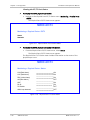
5. Navigate to Configuration > System > Management > Host IP.
The Host IP menu appears.
6. Type the new IP address into the Host IP field and then click Save.
The new IP address is assigned. You may continue specifying additional
parameters or connect to MiRICi-E3T3 from any PC on your network at a
later stage using the newly assigned IP address.
³
Before you disconnect MiRICi-E3T3:
1. Close all relevant management applications.
2. In the taskbar, double-click the Safely Remove Hardware icon.
The Safely Remove Hardware screen appears listing all USB devices
currently connected to your PC.
3. Select ADM8511 USB To Fast Ethernet Adapter from the Safely Remove
Hardware screen and click Stop.
A message appears confirming that you cam safely remove the device.
³
To disconnect MiRICi-E3T3 from the PC:
1. Push the release button at the front of MiRICi-E3T3 to disconnect it from
SFP-CA, and then eject MiRICi-E3T3 from the USB socket on SFP-CA.
2. Disconnect SFP-CA from the PC and from the power.
Note
• If you disconnect MiRICi-E3T3 and/or the SFP-CA module before releasing it,
your PC may stop responding.
• All SFP-CA modules have the same MAC address (00-00-E8-00-00-01).
MiRICi-E3T3 Ver. 2.2
Configuring MiRICi-E3T3 for First Use
3
Quick Start Guide
Configuring MiRICi-E3T3
2.
Note
³
Connecting MiRICi-E3T3 to the Host
You do not have to switch off the host unit when inserting or extracting the
MiRICi-E3T3 device.
To insert MiRICi-E3T3:
1. Set the DIP switches on MiRICi-E3T3’s underside to enable normal working
mode (see Figure 1).
2. Plug MiRICi-E3T3 into a free SFP (MSA-compatible) socket of the host device.
Make sure that MiRICi-E3T3 is pressed firmly into the MSA SFP port connector.
The device is ready to operate once the LOS LED has blinked three times.
Note
³
When MiRICi-E3T3 is inserted into the host, the LOS LED blinks three times if the
device is in normal or CONFIG mode; or blinks continuously if the device is in INIT
DB mode. The LOS LED stays OFF if the device is in SW Dwnld mode.
To connect to the E3/T3:
•
³
Use the miniature BNC cables (included in the MiRICi-E3T3 package) to
connect MiRICi-E3T3 to the coaxial E3/T3 line.
To eject MiRICi-E3T3:
1. Disconnect cables attached to MiRICi-E3T3.
2. Push the release button on the front of MiRICi-E3T3. This extracts the device
from the edge connector.
3. Remove MiRICi-E3T3 from the socket.
4
Connecting MiRICi-E3T3 to the Host
MiRICi-E3T3 Ver. 2.2
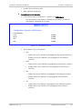
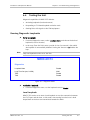
Contents
Introduction ............................................................................................................................ 1-1 1.1 Overview.................................................................................................................... 1-1 Applications ............................................................................................................ 1-1 Features ................................................................................................................. 1-2 Flow control ....................................................................................................... 1-2 Fault Propagation ............................................................................................... 1-2 Quality of Service ............................................................................................... 1-2 Loop Detection .................................................................................................. 1-2 Encapsulation..................................................................................................... 1-3 I2C Cycle Stretching ............................................................................................ 1-3 Management ...................................................................................................... 1-3 Detecting Errors ................................................................................................. 1-3 Statistics ............................................................................................................ 1-3 1.2 Physical Description ................................................................................................... 1-4 1.3 Functional Description................................................................................................ 1-5 Loop Detection ....................................................................................................... 1-5 Encapsulation ......................................................................................................... 1-5 GFP .................................................................................................................... 1-5 HDLC/cHDLC ....................................................................................................... 1-5 1.4 Technical Specifications.............................................................................................. 1-6 Installation and Setup .............................................................................................................. 2-1 2.1 2.2 2.3 2.4 2.5 2.6 2.7 2.8 2.9 Introduction ............................................................................................................... 2-1 Site Requirements and Prerequisites .......................................................................... 2-1 Package Contents ...................................................................................................... 2-1 Required Equipment ................................................................................................... 2-2 Setting the Switches .................................................................................................. 2-2 Connecting MiRICi-E3T3 to the SFP-CA Module ............................................................ 2-3 Disconnecting MiRICi-E3T3 ......................................................................................... 2-3 Inserting MiRICi-E3T3 into a Host Unit ........................................................................ 2-4 Connecting MiRICi-E3T3 to E3/T3 Equipment............................................................... 2-4 Operation ............................................................................................................................... 3-1 3.1 Indicators .................................................................................................................. 3-1 3.2 Configuration and Management Alternatives .............................................................. 3-2 Working with the I2C Interface ................................................................................. 3-2 Working with the Web-Based Management Interface ............................................... 3-2 Requirements for Web Based Management......................................................... 3-2 Access Levels ..................................................................................................... 3-3 Configuring MiRICi-E3T3 for First Use .................................................................. 3-3 Navigating the Web-Based Management Menus .................................................. 3-5 Menu Map .............................................................................................................. 3-6 Configuration .......................................................................................................................... 4-1 4.1 Configuring for Management ...................................................................................... 4-1 Configuring the Host IP Parameters ......................................................................... 4-1 Entering Device Information .................................................................................... 4-2 MiRICi-E3T3 Ver. 2.2
i
Table of Contents
Installation and Operation Manual
Defining Management Access Permissions............................................................... 4-3 Configuring the Manager List .................................................................................. 4-3 Controlling Management Access .............................................................................. 4-5 Enabling/Disabling I2C Cycle Stretching .................................................................... 4-5 4.2 Configuring for Operation .......................................................................................... 4-6 Configuring the System-Level Parameters................................................................ 4-6 Configuring Fault Propagation ............................................................................ 4-6 Configuring Tx Disable Mode............................................................................... 4-8 Configuring LOS Behavior ................................................................................... 4-8 Configuring MiRICi-E3T3 at the Physical Level ........................................................ 4-10 Specifying the Interface Type ........................................................................... 4-10 Configuring the Ethernet Port ........................................................................... 4-11 Configuring the E3 Port .................................................................................... 4-11 Configuring the T3 Port .................................................................................... 4-12 Configuring MiRICi-E3T3 at the Application Level ................................................... 4-14 Configuring Quality of Service (QoS) ................................................................. 4-14 Configuring Loop Detection .............................................................................. 4-15 4.3 Additional Tasks ....................................................................................................... 4-16 Displaying the MiRICi-E3T3 Inventory ..................................................................... 4-16 Displaying the MiRICi-E3T3 Status ......................................................................... 4-16 Displaying System Status Information ............................................................... 4-16 Displaying the Physical Layer Status ................................................................. 4-17 Restoring Defaults ................................................................................................ 4-19 Resetting MiRICi-E3T3 ........................................................................................... 4-19 Configuring Typical Applications ............................................................................................... 5-1 5.1 Configuring MiRICi-E3T3 ............................................................................................. 5-2 Configuring the Host IP Parameters ......................................................................... 5-2 Controlling Management Access .............................................................................. 5-2 Configuring the Ethernet Port ................................................................................. 5-3 Configuring the E3/T3 Port ...................................................................................... 5-3 Troubleshooting and Diagnostics.............................................................................................. 6-1 6.1 Monitoring Performance ............................................................................................. 6-1 Displaying Ethernet Statistics .................................................................................. 6-1 Displaying E3/T3 Statistics ...................................................................................... 6-3 6.2 Detecting Errors ......................................................................................................... 6-4 6.3 Handling Alarms and Traps ......................................................................................... 6-5 Displaying Events .................................................................................................... 6-5 Clearing Events ....................................................................................................... 6-6 Traps Generated by MiRICi-E3T3 .............................................................................. 6-6 6.4 Testing the Unit ......................................................................................................... 6-7 Running Diagnostic Loopbacks ................................................................................ 6-7 Local Loopback .................................................................................................. 6-7 Remote Loopback .............................................................................................. 6-8 Activating T3 Inband Loopbacks.......................................................................... 6-8 Sending RDI or AIS to the TDM Equipment ............................................................... 6-8 6.5 Technical Support ...................................................................................................... 6-8 ii
MiRICi-E3T3 Ver. 2.2
Installation and Operation Manual
Table of Contents
Connector Wiring ..................................................................................................................... A-1 Upgrading Software ................................................................................................................. B-1 I2C Interface Management ....................................................................................................... C-1 MiRICi-E3T3 Ver. 2.2
iii
Table of Contents
iv
Installation and Operation Manual
MiRICi-E3T3 Ver. 2.2
Chapter 1
Introduction
1.1
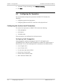
Overview
MiRICi-E3T3 is a remote bridge that forwards Fast Ethernet or Gigabit Ethernet
LAN packets to TDM-based WAN at full duplex wire-speed, fully utilizing the
expensive E3/T3 rate TDM circuit bandwidth.
Applications
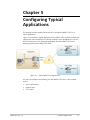
Figure 1-1. Providing Transparent LAN Services over Leased Lines
MiRICi-E3T3 Ver. 2.2
Overview
1-1
Chapter 1 Introduction
Installation and Operation Manual
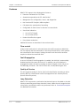
Features
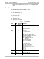
MiRICi-E3T3 supports the following basic features:
•
Framed or unframed for E3/T3 links
•
Standard encapsulation via GFP, HDLC/cHDLC
•
Management for configuration, status, and diagnostics.
•
Hot-insertion SFP footprint, MSA compliant
•
Full duplex wire-speed packet forwarding
•
Configurable Tx clock source for Receive or Internal clock
•
Visual fault indication:
Loss of E3/T3 signal
Loss of Ethernet link
•
Product identification support
•
Easy release mechanism
Additional features are described in the sections below.
Flow control
A flow control mechanism is activated when LAN traffic exceeds the WAN link’s
(E3/T3) capacity and the watermarks of the internal frame buffer. Pause packets
are transmitted to the LAN port, halting LAN traffic until the buffer has been
emptied to below the watermark limit.
Fault Propagation
In case of LOS and if Fault Propagation is enabled, the LAN link is automatically
disabled and the link status LED turns off. In addition, the LOS indication is
propagated towards the host by sending an electrical signal via the LOS pin on
the MSA edge connector. The LOS LED turns ON, visually indicating the LOS.
Quality of Service
The unit supports Quality of Service (QoS) with classification according to VLAN
priority (802.1p). Classification results are mapped into four transmit priority
queues with strict priority.
Loop Detection
MiRICi-E3T3 incorporates a mechanism that detects loops on the WAN or the LAN
side by transmitting special loop detection frames. When the unit recognizes that
a loop exists, preventative actions are performed. Refer to Functional Description
for additional information.
1-2
Overview
MiRICi-E3T3 Ver. 2.2
Installation and Operation Manual
Chapter 1 Introduction
Encapsulation
MiRICi-E3T3 supports the GFP-F, HDLC/cHDLC protocols.
I2C Cycle Stretching
MiRICi-E3T3 can be configured to operate with or without I2C cycle stretching
functionality. Refer to Appendix C for additional information.
Management
The unit can be managed via Web browser or I2C channel.
Detecting Errors
You can run diagnostic loopbacks on the E3/T3 ports, as well as send RDI or AIS
to the TDM equipment.
You can define up to 10 management stations to which to send SNMP traps. For
each management station, you can enable or disable sending traps.
Statistics
MiRICi-E3T3 provides the following statistics:
MiRICi-E3T3 Ver. 2.2
•
Ethernet statistics based on RFC 2819 (R-MON)
•
E3/T3 statistics.
Overview
1-3
Chapter 1 Introduction
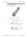
1.2
Installation and Operation Manual
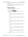
Physical Description
MiRICi-E3T3 is an SFP device that is inserted into an SFP MSA compatible
receptacle in a host unit.
Figure 1-2. MiRICi-E3T3 3D View
The dimensions of MiRICi-E3T3 are illustrated in Figure 1-3.
Figure 1-3. MiRICi-E3T3 Dimensions
1-4
Functional Description
MiRICi-E3T3 Ver. 2.2
Installation and Operation Manual
1.3
Chapter 1 Introduction
Functional Description
Loop Detection
MiRICi-E3T3 incorporates a mechanism that detects loops on the WAN or the LAN
side by transmitting special loop detection frames. When the unit recognizes that
a loop exists, it reacts according to the following protocol:
•
If a loop is detected on the LAN side, a loop detection alarm is sent.
•
If a loop is detected on the WAN side, the unit blocks the traffic and a loop
detection alarm is sent.
Encapsulation
GFP
MiRICi-E3T3 supports GFP-F. This protocol maps each client frame into a single
GFP frame. GFP-F is used where the client signal is framed or packetized by the
client protocol. GFP-F is not supported in framed E3 mode.
HDLC/cHDLC
MiRICi-E3T3 supports HDLC and cHDLC. The HDLC/cHDLC protocol is a layer 2 data
transmission protocol that ensures error-free movement of data. It also provides
a flow control mechanism.
cHDLC is a Cisco propriety version of the HDLC protocol. One of the primary
reasons for the creation of cHDLC is to address the HDLC protocol's inability to
provide multiprotocol support. Thus, cHDLC frames contain a field for identifying
the network protocol being encapsulated.
MiRICi-E3T3 Ver. 2.2
Technical Specifications
1-5
Chapter 1 Introduction
1.4
Installation and Operation Manual
Technical Specifications
E3 WAN INTERFACE
Number of Ports
1
Compliance
G.703, G.775, G.823, G.832
Data Rate
34.368 Mbps
Line Code
HDB3, AMI
Framing
Framed (G.832, G.751), unframed
Line Impedance
75Ω, unbalanced
Transmit Clock
Receive or internal clock
Connector
DIN 1.0/2.3
Cable Length (max)
275m (900 ft) with RG59 indoor cable
T3 WAN INTERFACE
Number of Ports
1
Compliance
GR-499-CORE, T1.107, T1.404, G.703, G.704,
G.775, G.824
Data Rate
44.736 Mbps
Line Code
B3ZS, AMI
Framing
Framed (M23, C-Bit), unframed
Line Impedance
75Ω, unbalanced
Transmit Clock
Receive or internal clock
Connector
DIN 1.0/2.3
Cable Length (max)
275m (900 ft) with RG59 indoor cable
Type
Fast or Gigabit Ethernet port
Compliance
IEEE 802.3
Edge Connector
SFP transceiver, MSA compliant
LAN INTERFACE
1-6
Technical Specifications
MiRICi-E3T3 Ver. 2.2
Installation and Operation Manual
Chapter 1 Introduction
Frame Size
MiRICi-E3T3/FE: 64–2016 bytes
MiRICi-E3T3/GbE: Up to 10 kbytes (Jumbo)
Encapsulation
GFP-F (G.8040, G.7041/Y.1303)
WAN PROTOCOL
HDLC
cHDLC
GENERAL
LED Indicators
MiRICi-E3T3/FE: LINK (green) – Ethernet link status
MiRICi-E3T3/GbE: LINK/ACT (green) – Ethernet link
status and activity
LOS (red) – E3/T3 loss of signal
MiRICi-E3T3 Ver. 2.2
Power
3.3V
Thermal Management
Power dissipation less than 1.25W
Dimensions
Height:
Width:
Depth:
Weight
Environment
Temperature: -40 to 65˚C (-40 to 149˚F)
Humidity:
Up to 90%, non-condensing
12.4 mm (0.49 in)
14 mm (0.55 in)
79 mm (3.11 in)
15.0 g (0.5 oz)
Technical Specifications
1-7
MiRICi-E3T3 Ver. 2.2
Technical Specifications
1-8
Chapter 2
Installation and Setup
2.1
Introduction
Housed in a Small Form Factor Pluggable (SFP) package, MiRICi-E3 and MiRICi-T3
comply with the Multi-Source Agreement (MSA) and can be inserted into any
MSA-compatible host unit.
MiRICi-E3T3 is an autonomous plug-and-play hot-insertion module. You can
configure a MiRICi unit while it is plugged into the host device or by using RAD’s
SFP-CA configuration module illustrated in Figure 2-2.
MiRICi-E3T3 is equipped with DIP switches on its underside that enable setting
the MiRICi unit to various operation modes. Operation modes depend on the
desired task and are listed in Table 2-1 together with the associated DIP switch
settings.
In addition, MiRICi-E3T3 can be managed via an I2C Interface (out-of-band) and/or
a Web-based management interface. For additional information, refer to
Chapter 4.
2.2
Site Requirements and Prerequisites
MiRICi-E3T3 is intended for installation in a free SFP (MSA-compatible) socket of
the host equipment.
The ambient operating temperature should be –40°C to 65°C (–40°F to 149°F),
at a relative humidity of up to 90%, non-condensing.
2.3
Package Contents
The MiRICi-E3T3 package includes the following items:
MiRICi-E3T3 Ver. 2.2
•
Up to four MiRICi-E3T3 units
•
Two adapter cables CBL-1023-BNC.
•
SFP-CA configuration adapter module (if ordered).
Package Contents
2-1
Chapter 2 Installation and Setup
2.4
Installation and Operation Manual
Required Equipment
MiRICi-E3T3 requires no special tools for installation.
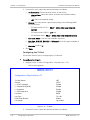
2.5
Setting the Switches
MiRICi-E3T3 includes a 2-section DIP switch used to select one of the following
working modes of the device:
³
•
Database initialization
•
Normal operation
•
Software download
•
Configuration.
To select the working mode:
•
On MiRICi-E3T3’s underside, set the DIP switches as listed in Table 2-1 to
enable the desired working mode.
SW2
SW2
SW1
State
OFF
OFF
ON
ON
OFF
ON
OFF
ON
INIT DB
Normal
SW Dwnld
Config
OFF
ON
SW1
Figure 2-1. DIP Switch Location
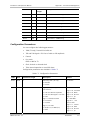
Table 2-1. DIP Switch Settings
Switch Position
Function
2-2
Setting the Switches
SW2
SW1
OFF
OFF
Database initialization
OFF
ON
Normal operation (factory setting)
ON
OFF
Software download
ON
ON
Configuration
MiRICi-E3T3 Ver. 2.2
Installation and Operation Manual
2.6
Chapter 2 Installation and Setup
Connecting MiRICi-E3T3 to the SFP-CA Module
For first use, you have to assign an IP address to MiRICi-E3T3 and specify a mode
of operation. To do so, you can use RAD’s SFP-CA module illustrated in
Figure 2-2. You can also use this module to upgrade MiRICi-E3T3’s software.
When you connect SFP-CA to a specific PC for the first time, you have to install
the SFP-CA driver on that PC, and configure the PC network parameters for
communication with SFP-CA. Refer to Chapter 3 for details.
Note
³
All SFP-CA modules have the same MAC address (00-00-E8-00-00-01).
To connect MiRICi-E3T3 to the SFP-CA unit:
1. Choose the desired operation mode using the DIP switches on MiRICi-E3T3’s
underside as explained in Required Equipment
2. MiRICi-E3T3 requires no special tools for installation.
3. Setting the Switches.
4. Connect the DC adapter to the SFP-CA configuration module and use the
power cord to connect the DC adapter to the mains.
5. Plug the USB connector of SFP-CA into a free USB port of a PC.
6. Plug MiRICi-E3T3 into the SFP socket on the opposite side on the SFP-CA unit.
To the DC
Adapter
To a USB Port on a PC
MiRICi-E3T3
Figure 2-2. SFP-CA Configuration Module
2.7
Disconnecting MiRICi-E3T3
Before physically disconnecting MiRICi-E3T3, you have to first release the device
using the Safely Remove Hardware utility.
³
To release MiRICi-E3T3:
1. Close all relevant management applications.
2. In the taskbar, double-click the Safely Remove Hardware icon.
MiRICi-E3T3 Ver. 2.2
Disconnecting MiRICi-E3T3
2-3
Chapter 2 Installation and Setup
Installation and Operation Manual
The Safely Remove Hardware screen appears listing all USB devices
currently connected to your PC.
3. Select ADM8511 USB To Fast Ethernet Adapter and click Stop.
A message appears confirming that you can safely remove the device.
Note
³
If you disconnect MiRICi-E3T3 and/or the SFP CA module before releasing it, your
PC may stop responding.
To disconnect MiRICi-E3T3 from the PC:
1. Push the release button at the front of MiRICi-E3T3, and then eject MiRICiE3T3 from SFP-CA.
2. Disconnect SFP-CA from the PC and from the power.
2.8
Inserting MiRICi-E3T3 into a Host Unit
This chapter explains how to connect (eject) MiRICi-E3T3 to (from) a host unit.
Note
³
You do not have to switch off the host unit when inserting or extracting
MiRICi-E3T3.
To insert MiRICi-E3T3:
1. Set the DIP switches to the desired operation mode as specified in Table 2-1.
2. Insert MiRICi-E3T3 into a free SFP (MSA-compatible) socket of the host
equipment.
3. Press MiRICi-E3T3 firmly into the MSA SFP port connector.
MiRICi-E3T3 is ready to operate.
³
To eject MiRICi-E3T3:
1. Disconnect cables attached to MiRICi-E3T3.
2. Push the release button at the front of MiRICi-E3T3. This extracts the device
from the edge connector.
3. Remove MiRICi-E3T3 from the socket.
2.9
Connecting MiRICi-E3T3 to E3/T3 Equipment
MiRICi-E3T3 can be connected to E3/T3 equipment.
³
To connect to E3/T3 equipment:
•
2-4
Use the miniature BNC cables (included in the MiRICi-E3T3 package), to
connect MiRICi-E3T3 to the coaxial E3 or T3 lines.
Connecting MiRICi-E3T3 to E3/T3 Equipment
MiRICi-E3T3 Ver. 2.2
Chapter 3
Operation
This chapter:
•
Provides a detailed description of the MiRICi-E3T3 LED indicators and their
functions
•
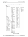
Lists alternative methods of the product configuration, explaining I2C and Web
browser management applications and illustrating management menus.
For additional information on parameters and menus, refer to Chapter 4.
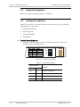
3.1
Indicators
The front of MiRICi-E3T3 has two status LEDs. Refer to Table 3-1 for the
functions of the LED indicators. The LEDs indicate link status and operation
modes during normal operation as well as while powering up.
When MiRICi-E3T3 is powered on, the LOS LED turns on for five seconds. For
MiRICi-E3T3/FE, the LINK LED also turns on for five seconds. During the first five
seconds, MiRICi-E3T3 is ready to respond to I2C messages without signal
stretching. Then while MiRICi-E3T3/FE boots up its application software and
performs startup configuration, the LOS LED blinks three times (if MiRICi-E3T3
mode is NORMAL or CONFIG).
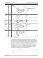
Table 3-1. LED Indicators
Note
MiRICi-E3T3 Ver. 2.2
LED
Function
MiRICi-E3T3/FE:
LINK (green)
ON – Ethernet link is connected
OFF – Ethernet link is disconnected
MiRICi-E3T3/GbE:
LINK/ACT (green)
ON – Ethernet link is connected
Blinking – Activity on Ethernet link
OFF – Ethernet link is disconnected
LOS (red)
ON – No T3 signal detected
OFF – Valid T3 signal detected
LOS at power-up
Blinking three times – MiRICi-E3T3 is in NORMAL or CONFIG mode
Continuously blinking – MiRICi-E3T3 is in INIT DB mode
OFF – MiRICi-E3T3 is in SW DOWNLOAD mode
Certain Ethernet equipment may cause the LINK or LINK/ACT LED to turn on
before the T3 cable has been connected.
Indicators
3-1
Chapter 3 Operation
Installation and Operation Manual
3.2
Configuration and Management Alternatives
If required, MiRICi-E3T3 can be reconfigured, using the following ports and
applications:
•
•
Local out-of-band management via an I2C interface.
Local or remote inband management via the Fast Ethernet port, using RAD’s
Web-based application.
In order to choose the Normal mode, you have to set DIP switches located on
MiRICi-E3T3’s underside as listed in Chapter 2. If configured locally, you have to
insert MiRICi-E3T3 into the associated SFP-CA module and connect it to your PC
as explained in Chapter 2.
Working with the I2C Interface
MiRICi-E3T3 enables configuring and monitoring the current status and
performing diagnostics via the SFP edge connector’s I2C interface. Refer to
Appendix C for instructions and the required message format.
Working with the Web-Based Management Interface
You can locally or remotely configure and manage MiRICi-E3T3 using a Web-based
management interface. Chapter 4 illustrates menus and explains configuration
parameters.
Requirements for Web Based Management
•
³
3-2
Internet Explorer 6.0, running on Windows
Before you start using a Web browser for management or monitoring:
•
Enable scripts.
•
Configure the firewall that might be installed on your PC to allow access to
the destination IP address.
•
Disable pop-up blocking software, such as Google Popup Blocker. You may
also have to configure spyware and adware protecting software to accept
traffic from/to the destination IP address.
•
To prevent configuration errors, you must flush the browser’s cache
whenever you return to the same screen.
Configuration and Management Alternatives
MiRICi-E3T3 Ver. 2.2
Access Levels
To prevent unauthorized modification of the operating parameters, MiRICi-E3T3
supports two access levels:
³
•
Superuser (su) can perform all the activities supported by the MiRICi-E3T3
management facility, including defining new users.
•
User (user) has only read-only access rights.
To enter as a superuser:
1. Enter su as the user name.
2. Enter 1234 as the password.
This allows you to configure all MiRICi-E3T3 parameters.
³
To enter as a user:
1. Enter user as the user name.
2. Enter 1234 as the password.
This allows you to view the MiRICi-E3T3 parameters.
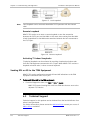
Configuring MiRICi-E3T3 for First Use
Before using MiRICi-E3T3 for the first time, you have to assign an IP address to it
that complies with your network requirements. You can do this by connecting it
to a PC via the SFP-CA adapter.
When you connect SFP-CA to a specific PC for the first time, you have to install
the SFP-CA driver on that PC, and configure the PC network parameters for
communication with SFP-CA.
³
To install the SFP-CA driver on a PC:
1. Insert the Technical Documentation CD into the CD drive of the PC.
The CD main menu appears.
2. Click the link to the MiRIC/MiRICi Family product page.
The MiRIC/MiRICi Family product page appears, with an entry for the
SFP-CA documentation and driver.
3. Double-click the SFP-CA driver link.
The SFP-CA driver is installed in the background. No further action is
required to install the driver.
Note
MiRICi-E3T3 Ver. 2.2
The SFP-CA driver requires Windows XP SP2 to be installed on the relevant PC.
Configuration and Management Alternatives
3-3
³
To configure the PC network parameters for the SFP-CA connection to
MiRICi-E3T3:
1. Connect the SFP-CA configuration unit to a USB port on your PC. For
additional information, refer to Chapter 2.
The New Hardware is Detected notice appears.
2. Right-click My Network Places.
A new local area network connection appears in the list of network
connections.
3. Right-click the new local area connection and rename it SFP-CA.
4. Right-click Properties, click Configure, and select the Advanced tab
The Network Connection Properties dialog box appears.
5. Choose Select Media and under Value, choose Home LAN, and then click OK.
The dialog box closes and your settings are applied.
6. Right-click the SFP-CA connection and click Properties.
The Local Area Connection Properties dialog box appears.
7. Select Internet Protocol (TCP/IP) and click Properties.
The Internet Protocol (TCP/IP) dialog box appears.
8. To enable entering TCP/IP settings, select Use the following IP Address.
The IP Address, the Subnet Mask and the Default Gateway field become
available.
9. Enter the following TCP/IP settings and then click OK:
IP Address: 192.168.205.20
Subnet Mask: 255.255.255.0
Default Gateway: 192.168.205.1
10. Close My Network Places.
The PC communication link with MiRICi-E3T3 is ready.
³
To assign a new IP address to MiRICi-E3T3:
1. Set MiRICi-E3T3 to Configuration mode, using its DIP switches (see
Chapter 2).
Note
Setting a different working mode via the DIP switches requires disconnecting
MiRICi-E3T3 from any device (SFP-CA or host).
2. Plug MiRICi-E3T3 into the SFP socket of the SFP-CA module.
3. Connect SFP-CA to your PC via USB 2.0 port.
The Ready LED on SFP-CA turns on.
MiRICi-E3T3 Ver. 2.2
Configuration and Management Alternatives
3-4
4. Open the Web browser and enter http://192.168.205.1 into the Web
browser’s address field.
The Opening screen appears.
5. Click Login.
The Login screen appears.
6. Enter the default user name su and the default password 1234 for Superuser
access, and then click Submit.
A menu appears to the left and you are able to configure MiRICi-E3T3.
7. From the Host IP menu (Configuration > System > Management > Host IP),
enter the new IP address, the IP mask, and the default gateway values.
8. Save the changes.
The new TCP/IP settings are assigned. You may continue specifying
additional parameters or connect to MiRICi-E3T3 from any PC on your
network at a later stage, using the newly assigned IP address.
Note
In Configuration mode, MiRICi-E3T3 responds to the default IP address
192.168.205.1 only, even if the IP address has been changed.
Navigating the Web-Based Management Menus
The MiRICi-E3T3 Web-based remote access management software provides a
user-friendly interface for configuring, collecting statistics and performing
diagnostic tests on the MiRICi-E3T3 units.
³
To choose an option:
1. Click a link in the screen to display the next menu.
2. Once the target screen is displayed, select a value from the dropdown list or
enter it in a text box.
MiRICi-E3T3 Ver. 2.2
Configuration and Management Alternatives
3-5
Chapter 3 Operation
Installation and Operation Manual
Menu Map
Use these menu trees as a reference aid while performing configuration and
control functions. Chapter 4 illustrates menus and explains parameters.
Figure 3-1 E3/T3 Menu Map
3-6
Configuration and Management Alternatives
MiRICi-E3T3 Ver. 2.2
Chapter 4
Configuration
This chapter illustrates the configuration MiRICi-E3T3 screens and explains their
parameters.
The menu map of the MiRICi-E3T3 management software can be found in
Chapter 3.
4.1
Configuring for Management
Before configuring MiRICi-E3T3 make sure to assign a new IP address, an IP mask
and a default gateway values to the unit’s host, as explained in Chapter 3. Once
the MiRICi-E3T3 host IP parameters are set, perform the following steps in order
to configure MiRICi-E3T3 for management:
Configuring the Host IP Parameters
In addition to defining the IP parameters of the MiRICi-E3T3 host (see Chapter 3),
the management software allows you to create a dedicated management VLAN in
order to separate management traffic from the user data.
³
To configure the host IP parameters:
1. Navigate to the Host IP menu (Configuration > System > Management >
Host IP).
The Host IP menu appears.
MiRICi-E3T3
Configuration > System > Management > Host IP
IP Address
192.168.205.1
IP Mask
255.255.255.0
Default Gateway
0.0.0.0
Host Tagging
Untagged
Figure 4-1. Host IP Menu
MiRICi-E3T3 Ver. 2.2
Configuring for Management
4-1
Chapter 4 Configuration
Installation and Operation Manual
2. From the Host IP menu (Configuration > System > Management > Host IP), do
the following:
Note
In the IP Address field, enter the host IP address
In the IP Mask field, enter the host IP mask.
In the Default Gateway field, set the default gateway IP address.
Set Host tagging to be Tagged or Untagged to consider or ignore the
VLAN tagging of the management traffic coming from the management
station.
If host tagging is enabled, two additional parameters appear:
Host VLAN ID (ID of the host VLAN): 1–4094
Host VLAN Priority (Priority of the host VLAN): 0–7
Before setting Host Tagging to Tagged, make sure that your PC is connected to
the VLAN or that another PC connected to the VLAN is available to continue
setting parameters.
Entering Device Information
The MiRICi-E3T3 management software allows you to assign a name to the unit,
add its description, specify its location to distinguish it from the other devices
installed in your system, and assign a contact person.
³
To enter device information:
1. Navigate to the Device Info menu
(Configuration > System > Management > Device Info).
The Device Info menu appears.
MiRICi-E3T3
Configuration > System > Management > Device Info
Description
T3 Intelligent Converter
Device Name
MiRICi-E3T3
Location
Contact Person
Figure 4-2. Device Info Menu
2. Select Device Name and enter a desired name for the MiRICi-E3T3 unit. The
default reflects the unit and the physical port type that you specified last, for
example MiRICi-E3.
3. In the Device Location field, enter the desired name for the current
MiRICi-E3T3 location.
4. In the Contact Person field, enter the name of a contact person.
4-2
Configuring for Management
MiRICi-E3T3 Ver. 2.2
Installation and Operation Manual
Chapter 4 Configuration
Defining Management Access Permissions
MiRICi-E3T3 management software allows the super user (su) to modify the super
user and guest user credentials.
³
To change the user name and/or the password:
1. Make sure that you are logged in as su.
2. Navigate to the User Access menu (Configuration > System > Management >
User Access).
The User Access menu appears.
MiRICi-E3T3
Configuration > System > Management > User Access
User Level
Super User
User Name
su
Old Password
New Password
Confirm New Password
Forward
Figure 4-3. User Access Menu
3. From the User Access menu, do the following:
Click Forward to select the desired user: Super User or User.
In the User Name field, assign a new user name.
In the Old Password field, enter the super user password used to log in
during the current management session.
In the New Password field, assign a new password.
In the Confirm New Password field, re-enter the new password to confirm
it.
4. Click Save.
Note
Make sure not to assign the same user name to the super user and the guest
user.
Configuring the Manager List
You define the managers and specify which manager(s) will receive SNMP traps.
Up to eight managers can be defined. Entering the IP address and corresponding
subnet mask identifies each management station. In addition, you can
MiRICi-E3T3 Ver. 2.2
Configuring for Management
4-3
Chapter 4 Configuration
Installation and Operation Manual
temporarily prevent a manager station from receiving traps, by masking the
network manager.
³
To define new managers:
1. Navigate to the Management Access menu (Configuration > System >
Management > Managers List).
The Managers List menu appears.
MiRICi-E3T3
Configuration > System > Management > Managers List
Manager ID
Manager IP
Manager Trap Mask
1
2
3
4
5
6
7
8
0.0.0.0
0.0.0.0
0.0.0.0
0.0.0.0
0.0.0.0
0.0.0.0
0.0.0.0
0.0.0.0
Disable
Disable
Disable
Disable
Disable
Disable
Disable
Disable
Figure 4-4. Managers List menu
2. In the Manager IP field, specify an IP address for the new manager.
3. In the Manager Trap Mask field, specify Disable or Enable to mask or unmask
traps for the new management station.
4. Select Save.
5. Repeat the previous four steps for each network manager you wish to add.
4-4
Configuring for Management
MiRICi-E3T3 Ver. 2.2
Installation and Operation Manual
Chapter 4 Configuration
Controlling Management Access
You can enable or disable Web access to MiRICi-E3T3 via WAN or LAN.
³
To enable or disable Web access to MiRICi-E3T3:
1. Navigate to the Management Access menu (Configuration > System >
Management > Management Access).
The Management Access menu appears.
MiRICi-E3T3
Configuration > System > Management > Management Access
LAN (Web)
Enable
WAN (Web)
Enable
Figure 4-5. Management Access Menu
2. From the Management Access menu, perform the following:
Enable or disable Web access to MiRICi-E3T3 via its LAN interface
Enable or disable Web access to MiRICi-E3T3 via its WAN interface.
3. Click Save.
Enabling/Disabling I2C Cycle Stretching
MiRICi-E3T3 can be configured to operate with or without the I2C cycle stretching
functionality. Refer to Appendix C for additional information.
³
To enable or disable I2C Cycle Stretching:
1. Navigate to the Outband menu (Configuration > System > Management >
Outband).
The Outband menu appears.
MiRICi-E3T3
Configuration > System > Management > Outband
Outband Mode
Normal
Outband Address
128
Figure 4-6. Outband Menu
2. To enable I2C Cycle Stretching, select Normal.
MiRICi-E3T3 Ver. 2.2
Configuring for Management
4-5
Chapter 4 Configuration
Installation and Operation Manual
3. To disable I2C Cycle Stretching, select Without Stretching.
4. Click Save.
4.2
Configuring for Operation
The recommended configuration procedure for MiRICi-E3T3 includes the
following:
•
Configuring system-level parameters
•
Configuring Ethernet and E3/T3 interfaces at the physical level.
Configuring the System-Level Parameters
The system-level parameters of MiRICi-E3T3 include the following:
•
Fault propagation
•
LOS behavior
•
Tx disable mode.
These parameters are configured via the System menu.
Configuring Fault Propagation
Fault propagation mechanism propagates the E3/T3 LOS signal to the
10/100BaseFx port. When the fault propagation is enabled, the Ethernet port is
disconnected if one of the following events is detected on the TDM interface:
4-6
•
Loss of signal (LOS)
•
Loss of frame (LOF)
•
Far-end alarm and control (FEAC)
•
Receive loss of lock (RLOL)
•
Remote defect indication (RDI)
•
Alarm indication SIGNAL (AIS)
Configuring for Operation
MiRICi-E3T3 Ver. 2.2
Installation and Operation Manual
Chapter 4 Configuration
Alternatively, you can disable propagation of any of the supported conditions to
the Ethernet port.
You can also specify the wait-to-restore (WTR) time. WTR refers to the time
period that MiRICi-E3T3 waits before reconnecting an interface once the failed
interface has been restored.
³
To configure the fault propagation:
1. Navigate to the System menu (Configuration > System).
The System menu appears.
2. Enable or disable Fault Propagation respectively.
3. When enabled, select Fault Propagation to display the relevant menu and
configure the following parameters:
LOS:
MiRICi-E3T3 Ver. 2.2
Disable (LOF on the TDM link is not propagated to the Ethernet
interface)
Enable (RLOL on the TDM link is propagated to the Ethernet interface)
Disable (RLOL on the TDM link is not propagated to the Ethernet
interface)
Enable (RDI on the TDM link is propagated to the Ethernet interface)
Disable (RDI on the TDM link is not propagated to the Ethernet
interface)
AIS:
Enable (LOF on the TDM link is propagated to the Ethernet interface)
RDI:
Disable (FEAC on the TDM link is not propagated to the Ethernet
interface)
RLOL:
Enable (FEAC on the TDM link is propagated to the Ethernet interface)
LOF:
Disable (LOS on the TDM link is not propagated to the Ethernet
interface)
FEAC:
Enable (LOS on the TDM link is propagated to the Ethernet interface)
Enable (AIS on the TDM link is propagated to the Ethernet interface)
Disable (AIS on the TDM link is not propagated to the Ethernet
interface)
Fault Propagation WTR (Wait-to-restore in seconds): 0-3600; 0 disables
the WTR.
Configuring for Operation
4-7
Chapter 4 Configuration
Installation and Operation Manual
MiRICi-E3T3
Configuration > System > Fault Propagation
Fault Propagation caused by:
LOS
FEAC
LOF
RLOL
RDI
AIS
Fault Propagation WTR (sec) [0..3600]
Disable
Disable
Disable
Disable
Disable
Disable
0
Figure 4-7. Fault Propagation Menu
Configuring Tx Disable Mode
MiRICi-E3T3 lets you configure how the system responds to disabling the Tx
connection.
³
To configure the Tx Disable Mode
1. In the System menu (Configuration > System), click Tx Disable Mode.
The Tx Disable Mode screen appears.
MiRICi-E3T3
Configuration > System > Tx Disable Mode
Tx Disable Behavior
Not Available
Figure 4-8. Tx Disable Mode Screen
2. To specify how the system is to respond when the Tx link fails:
Not Available. The Tx link failure has no impact on MiRICi-E3T3 and no
action is taken.
Tri-State. The E3/T3 framer is shut down.
AIS. The Alarm Indication signal is activated.
Configuring LOS Behavior
MiRICi-E3T3 allows you to define whether to send the LOS indication to the
Ethernet interface when one of the following conditions is detected on the TDM
link:
4-8
•
Loss of signal (LOS)
•
Receive loss of lock (RLOL)
Configuring for Operation
MiRICi-E3T3 Ver. 2.2
Installation and Operation Manual
³
Chapter 4 Configuration
•
Remote defect indication (RDI)
•
Alarm indication signal (AIS)
To configure the LOS behavior:
1. In the System menu (Configuration > System), click LOS Behavior.
The LOS Behavior menu appears, allowing you to enable or disable the
LOS behavior, depending on its cause.
MiRICi-E3T3
Configuration > System > LOS Behavior
LOS caused by:
LOS
RLOL
RDI
AIS
Disable
Disable
Disable
Disable
Figure 4-9. LOS Behavior Screen
2. Specify MiRICi-E3T3’s LOS behavior.
LOS:
Disable (RLOL on the TDM link is not propagated to the Ethernet
interface)
Enable (RDI on the TDM link is propagated to the Ethernet interface)
Disable (RDI on the TDM link is not propagated to the Ethernet
interface)
AIS:
MiRICi-E3T3 Ver. 2.2
Enable (RLOL on the TDM link is propagated to the Ethernet interface)
RDI:
Disable (LOS on the TDM link is not propagated to the Ethernet
interface)
RLOL:
Enable (LOS on the TDM link is propagated to the Ethernet interface)
Enable (AIS on the TDM link is propagated to the Ethernet interface)
Disable (AIS on the TDM link is not propagated to the Ethernet
interface)
Configuring for Operation
4-9
Chapter 4 Configuration
Installation and Operation Manual
Configuring MiRICi-E3T3 at the Physical Level
MiRICi-E3T3 allows you to configure for transmission over E3 or T3. You can
configure the Ethernet, E3, and T3 ports on the physical level.
Specifying the Interface Type
MiRICi-E3T3 can operate in both E3 and T3 environments without the need for
two different units.
³
To specify the interface type:
1. Navigate to the Physical Ports menu (Configuration > Physical Ports).
The Physical Ports menu appears.
MiRICi-E3T3
Configuration > Physical Ports
Ethernet
T3
Interface Type
T3
Figure 4-10. Interface Type Menu – Unit Currently in T3 Mode
2. Under Interface Type, select the desired interface type, T3 or E3 respectively.
3. Click Save.
The selected interface type appears and you are able to access the
associated parameters. The system reverts to the Main menu.
4-10
Configuring for Operation
MiRICi-E3T3 Ver. 2.2
Installation and Operation Manual
Chapter 4 Configuration
Configuring the Ethernet Port
This section instructs you on configuring the Ethernet port.
³
To configure the Ethernet port:
1. Navigate to the Ethernet menu (Configuration > Physical Ports > Ethernet).
The Ethernet menu appears.
MiRICi-E3T3
Configuration > Physical Ports > Ethernet
Rate
Flow Control
1000 Mbps (read-only)
Disable
Figure 4-11. Ethernet Menu
2. Under Flow Control, choose Enable if the receiving device is sending a Pause
frame. This is necessary when the transmitting device transmits faster than
the receiving device can receive.
3. Click Save.
Note
Possible rates are 100 or 1000 Mbps, depending on whether you are using a Fast
Ethernet (FE) or a Gigabit Ethernet (GbE) interface.
Configuring the E3 Port
This section instructs you on configuring the E3 interface.
³
To configure the E3 port:
1. Navigate to the E3 menu (Configuration > Physical Ports > E3).
The E3 menu appears.
MiRICi-E3T3
Configuration > Physical Ports > E3
Tx Clock Source
Protocol
Line Code
Line Type
Idle Code
LBT
HDLC
HDB3
E3 Unframed
7E
Figure 4-12. E3 Menu
MiRICi-E3T3 Ver. 2.2
Configuring for Operation
4-11
Chapter 4 Configuration
Installation and Operation Manual
2. From the E3 menu, select the desired parameters as follows:
Tx Clock Source. Choose the clock source of the Tx line.
Internal Clock. Select this option to choose the internal oscillator
source.
LBT. Link to the loopback timing.
Protocol. You may choose a protocol according to the following MiRICiE3T3 definitions:
E3 Framed mode (G.751) - HDLC or cHDLC (High Level Data Link
Control).
E3 Framed mode (G.832) – GFP only.
E3 Unframed mode - HDLC or cHDLC (High Level Data Link Control).
Line Code. HDB3 is the line code available at present.
Line Type. E3 G.751, E3 G.832 or Unframed are the line types available at
present.
Idle Code. Fixed to 7E.
3. Click Save.
Configuring the T3 Port
This section instructs you on configuring the T3 interface.
³
To configure the T3 port:
1. Navigate to the T3 menu (Configuration > Physical Ports > T3).
The T3 menu appears.
MiRICi-E3T3
Configuration > Physical Ports > T3
Tx Clock Source
Protocol
(----VCAT overhead
(----Payload FCS(32 Bit)
(----Scrambler
(----GFP Keep Alive
Line Code
Line Type
FEAC Code Receive
Line Length
LBT
GFP-F
Disable
Disable
Enable
Disable
B3ZS
T3 C-bit
Enable
Up to 225ft
Figure 4-13. T3 Menu
2. From the T3 menu, select the desired parameters as follows:
4-12
Configuring for Operation
MiRICi-E3T3 Ver. 2.2
Installation and Operation Manual
Tx Clock Source. Choose the clock source of the Tx line.
Chapter 4 Configuration
Internal Clock. Select this option to choose the internal oscillator
source.
LBT. Link to the loopback timing.
Protocol. You may choose a protocol according to the following MiRICiE3T3 definitions:
T3 Framed mode – GFP, HDLC or cHDLC (High Level Data Link
Control).
T3 Unframed mode - HDLC or cHDLC (High Level Data Link Control)
VCAT Overhead. If enabled, VCAT header is added to frames (only in GFP
mode).
Payload FCS (32 Bit). If enabled, a frame check sequence field is carried
by every frame as a payload for error detection (only in GFP mode).
Scrambler. If enabled and supported on both ends, information such as
emails or voice gets truncated until it arrives at its destination (only in
GFP mode).
GFP Keep Alive. If enabled, MiRICi-E3T3 sends 2-3 keep alive messages
per second. You should enable this parameter if MiRICi-E3T3 is used with
old equipment and LOFs are frequently encountered (only in GFP mode).
Line Code. You may choose either B3ZS or AMI.
B3ZS. A T-carrier line code, referred to as bipolar with three-zero
substitution, in which bipolar violations are deliberately inserted if the
stream of user data contains a string of 3 or more consecutive zeros.
AMI. Referred to as Alternate Mark Inversion because a 1 is referred
to as a mark and a 0 as a space.
Line Type. T3 C-bit , T3 M23 or T3 Unframed (only in cHDLC or HDLC
mode) are the line types available at present.
FEAC Code Receive. If enabled, FEAC bit codes for “Loop up” and “Loop
down” commands are processed, otherwise they are ignored.
Line Length. This parameter refers to Line Build Out.
Up to 225 ft. The transmitted signal complies with the pulse mask
standard (G.703) for a cable length of up to 225 ft.
225 ft to 900 ft. The transmitted signal complies with the pulse mask
standard (G.703) for a cable length between 225 ft and 450 ft.
Idle Code. Fixed to 7E (only in HDLC or cHDLC mode)
3. Click Save.
MiRICi-E3T3 Ver. 2.2
Configuring for Operation
4-13
Chapter 4 Configuration
Installation and Operation Manual
Configuring MiRICi-E3T3 at the Application Level
Configuring Quality of Service (QoS)
MiRICi-E3T3 supports Quality of Service (QoS) with classification according to
VLAN priority (802.1p). Classification results are mapped into four transmit
priority queues with strict priority
³
To assign priorities to traffic queues:
1. Navigate to Main Menu > Configuration > Applications > QoS.
The QoS Mapping menu appears.
MiRICi-E3T3
Configuration > Applications > QoS
User Priority 0
User Priority 1
User Priority 2
User Priority 3
User Priority 4
User Priority 5
User Priority 6
User Priority 7
Traffic Class 0
Traffic Class 0
Traffic Class 0
Traffic Class 0
Traffic Class 0
Traffic Class 0
Traffic Class 0
Traffic Class 0
Table 4-1 QoS Mapping Menu
2. From the QoS Mapping menu, choose the desired priority (0 – 7) and select
the assigned traffic queue number (0 – 3). Each traffic queue can be assigned
to more than one priority.
These are priority queues, i.e. packets arriving with lower priority will only be
transmitted after all packets with higher priority have been transmitted. It
implies possible starvation of lower priority traffic in case higher priority
traffic uses all available bandwidth.
Note
Class 0 (the default one) has lowest priority, 3 highest.
3. Repeat steps 1 – 3 for all priorities.
4. Select Save.
4-14
Configuring for Operation
MiRICi-E3T3 Ver. 2.2
Configuring Loop Detection
MiRICi-E3T3 features a mechanism to detect loops on the LAN side or WAN side
by transmitting special loop detection frames.
³
To configure loop detection:
1. Navigate to Main Menu > Configuration > Applications > Loop detection.
The Loop Detection menu appears.
MiRICi-E3T3
Configuration > Applications > Loop Detection
Loop Detection VLAN [1..4095]
1
LAN Loop Detection
Disable
WAN Loop Detection
Disable
Table 4-2 Loop Detection Menu
2. From the Loop Detection menu, select the desired parameters as follows:
Note
Loop Detection VLAN. Choose the VLAN identification number of the loop
detection frame (1..4095).
LAN Loop Detection. If enabled the loop detection mechanism is activated
for the LAN side
WAN Loop Detection. If enabled the loop detection mechanism is
activated for the WAN side
Data is normally sent to and from the MiRICi-E3T3 via the LAN/WAN. Once loop
detection is enabled, the unit starts transmitting special loop detection frames.
If the unit recognizes that a loop exists, the following actions are performed
according to the direction/location of the loop:
If a loop exists on the LAN side the unit sends a loop detection alarm
accordingly.
If a loop exists on the WAN side the unit stops the traffic to the WAN side
and then sends a loop detection alarm accordingly.
3. Select Save.
MiRICi-E3T3 Ver. 2.2
4-15
4.3
Additional Tasks
This section describes additional operations available supported by the
MiRICi-E3T3 management software, including the following:
•
Displaying inventory
•
Displaying the MiRICi-E3T3 status information at the system and physical
levels
•
Restoring defaults
•
Resetting the unit
•
Setting options for testing the system during runtime.
Displaying the MiRICi-E3T3 Inventory
The MiRICi-E3T3 inventory displays description of the unit, its hardware, firmware
and software revisions, serial number etc.
To display the MiRICi-E3T3 inventory:
³
•
From the Main menu, select Inventory.
The Inventory menu appears.
MiRICi-E3T3
Inventory
ID Description
Vendor Type Class Entity Name HWRev FWRev
SWRev
Serial No
1
0
2.0E01
1.00
MiRICi-T3-
3
Chassis
MiRICi-T3-
0.0
0.0
Alias
Asset ID
FRU
0
True
Chassis
Figure 4-14. Inventory Screen
Displaying the MiRICi-E3T3 Status
The MiRICi-E3T3 software provides access to the following status information:
•
System level – MAC address and system uptime period
•
Physical ports – status of the physical layer alarms and errors.
Displaying System Status Information
The System menu includes the following:
MiRICi-E3T3 Ver. 2.2
•
MAC address of the MiRICi-E3T3 unit
•
MiRICi-E3T3 uptime (time elapsed since the last reset in hh:mm:ss format).
Additional Tasks
4-16
Installation and Operation Manual
³
Chapter 4 Configuration
To display the system status information:
•
From the Monitoring menu, select System.
The system (MAC) address and the time that the system runs since the
last reset (system up time) appear as illustrated in Figure 4-15.
MiRICi-E3T3
Monitoring > System
MAC Address
00-20-d2-26-54-e7
System Uptime
04.59.02
Log File
Figure 4-15. System Status Screen
You can select Log File to display the logged events for the system level (see
Chapter 6).
Displaying the Physical Layer Status
You can view the status of LAN and TDM connections at the physical level.
Viewing the Ethernet Port Status
³
To display the Ethernet physical layer status:
•
Navigate to the Physical Ports Ethernet Status menu (Monitoring >
Physical Ports > Ethernet).
The Physical Ports Ethernet Status menu appears.
MiRICi-E3T3
Monitoring > Physical Ports > Ethernet
Operational status
UP
LAN Loop detected
OFF
Statistics
Figure 4-16 Ethernet Port Status Menu
You can change the direction of the operational status by selecting UP or DOWN
from the Ethernet Port Status menu (see Figure 4-16). LAN Loop detected–Loop
detected (ON), Loop not detected or loop detection not activated (OFF)
You can select Statistics to display the logged statistical counters for the
Ethernet physical layer (see Chapter 6)
MiRICi-E3T3 Ver. 2.2
Additional Tasks
4-17
Chapter 4 Configuration
Installation and Operation Manual
Viewing the E3/T3 Port Status
³
To display the E3/T3 physical layer status:
•
Navigate to the Physical Ports E3/T3 Status menu (Monitoring > Physical Ports
> E3/T3).
The Physical Ports E3/T3 Status menu appears.
MiRICi-E3T3
Monitoring > Physical Ports > E3/T3
Status
Statistics
Figure 4-17 Physical Ports E3/T3 Status Menu
³
To display the E3/T3 physical layer status information:
•
From the Physical Ports E3/T3 Status menu, select Status
The Physical Ports E3/T3 Status menu appears.
The Physical Ports E3/T3 Status menu includes information on the status of the
physical layer errors.
MiRICi-E3T3
Monitoring > Physical Ports > Status
LOS (Red Alarm)
ON
LOF (Red Alarm)
ON
RDI (Yellow Alarm)
ON
AIS (Blue Alarm)
OFF
OOF
ON
RL OL
ON
TX Disable
OFF
WAN Loop detected
OFF
Figure 4-18. Physical Ports T3 Status Menu
4-18
Additional Tasks
MiRICi-E3T3 Ver. 2.2
Table 4-3. Status Indicators
Parameter
Description
LOS
Loss of Signal encountered (ON), resolved (OFF)
LOF
Loss of Frame (ON), resolved (OFF)
RDI
Remote Alarm Indication (ON), resolved (OFF)
AIS
Alarm Indication Signal (ON), resolved (OFF)
OOF
Out of Frame (ON), resolved (OFF)
RL OL
LIU Out of Lock (ON)
TX Disable
Tx connection disabled (ON), enabled (OFF)
Wan Loop detected
Loop detected (ON), Loop not detected or loop
detection not activated (OFF)
You can select Statistics to display the logged statistical counters for the E3/T3
physical layer (Refer to Troubleshooting and Diagnostics).
Restoring Defaults
You can restore the MiRICi-E3T3 default settings.
³
To restore the MiRICi-E3T3 default settings:
1. From the System menu (Configuration > System), select Set Factory Defaults.
You are asked to confirm your request.
2. Click Yes to confirm your request.
MiRICi-E3T3 is reset and all settings are reset to the factory default.
Resetting MiRICi-E3T3
You can perform an overall reset of MiRICi-E3T3.
³
To reset MiRICi-E3T3:
1. In the System menu (Configuration > System), select Reset Device.
You are asked to confirm your request.
2. Click Yes to confirm your request.
MiRICi-E3T3 is reset and all parameters configured before saving them
last are preserved.
MiRICi-E3T3 Ver. 2.2
Additional Tasks
4-19
MiRICi-E3T3 Ver. 2.2
Additional Tasks
4-20
Chapter 5
Configuring Typical
Applications
This chapter provides detailed instructions for configuring MiRICi-E3T3 for a
typical application.
Figure 5-1 illustrates a typical application where MiRICi-E3T3 provides transparent
LAN services over leased lines to connect branches to the headquarters over the
E3/T3 infrastructure. The illustrated application illustrates MiRICi-E3T3 units
working opposite other MiRICi-E3T3 units.
Figure 5-1. Typical MiRICi-E3T3 Application
You have to configure the following for each MiRICi-E3T3 unit (in any suitable
order):
MiRICi-E3T3 Ver. 2.2
•
Host IP parameters
•
Ethernet port
•
E3/T3 ports.
Configuring MiRICi-E3T3
5-1
Chapter 5 Configuring Typical Applications
5.1
Installation and Operation Manual
Configuring MiRICi-E3T3
MiRICi-E3T3, connected to host devices such as routers or switches, forwards
Fast Ethernet or Gigabit Ethernet LAN packets to TDM-based WAN at full duplex
wire speed over E3 or T3 lines. Every MiRICi-E3T3 unit must be configured
separately.
Configuring the Host IP Parameters
The IP address serves as a destination for the management traffic. The default IP
address is 192.168.205.1. You have to assign a new IP address that is suitable
for your application.
³
To configure the host IP parameters:
1. In the IP address field of the Host IP menu (Configuration > System >
Management), assign new IP addresses 10.10.10.1, 10.10.10.2, etc. to each
MiRICi-E3T3 unit.
2. Assign the new IP mask 255.255.255.0 to all MiRICi-E3T3 units. All
MiRICi-E3T3 units and the management station must belong to the same
subnet.
3. Leave the remaining parameters unchanged.
MiRICi-E3T3
Configuration > System > Management > E3 > Host IP
IP Address
10.10.10.1
IP Mask
255.255.255.0
Default Gateway
0.0.0.0
Host Tagging
Untagged
Figure 5-2. Host IP Menu (First MiRICi-E3T3 Unit)
Controlling Management Access
You can enable or disable Web access to MiRICi-E3T3 via WAN or LAN.
³
To enable or disable Web access to MiRICi-E3T3:
1. Navigate to the Management Access menu (Configuration > System >
Management > Management Access).
The Management Access menu appears.
2. Enable Web Access via both the LAN and the WAN interfaces.
3. Click Save.
5-2
Configuring MiRICi-E3T3
MiRICi-E3T3 Ver. 2.2
Installation and Operation Manual
Chapter 5 Configuring Typical Applications
Configuring the Ethernet Port
If the transmitting device transmits faster than the receiving device can receive,
you have to enable flow control, allowing MiRICi-E3T3 to send a pause frame
when necessary.
³
To enable Flow Control:
•
In the Flow Control field of the Ethernet menu (Configuration > Physical Ports
> Ethernet), select Enable.
MiRICi-E3T3
Configuration > Physical Ports > Ethernet
Rate
Flow Control
1000 Mbps
Enable
Figure 5-3. Ethernet Menu
Configuring the E3/T3 Port
You have to configure the T3 interface as follows.
³
To choose the interface type T3:
1. Navigate to the Physical Ports menu (Configuration > Physical Ports).
The Physical Ports menu appears.
MiRICi-E3T3
Configuration > Physical Ports
Ethernet
E3
Interface Type
T3
Figure 5-4. Physical Ports Menu – Unit Currently in E3 Mode
2. Under Interface Type, select T3.
3. Click Save.
The unit is set to the selected interface type and the system reverts to
the Main menu.
MiRICi-E3T3 Ver. 2.2
Configuring MiRICi-E3T3
5-3
Chapter 5 Configuring Typical Applications
³
Installation and Operation Manual
To configure the T3 port:
1. Navigate to the T3 menu (Configuration > Physical Ports > T3).
MiRICi-E3T3
Configuration > Physical Ports > T3
Tx Clock Source
Protocol
Internal Clock
GFP-F
(----VCAT Overhead
(----Payload FCS(32 Bit)
(----Scrambler
(----GFP Keep Alive
Line Code
Line Type
FEAC Code Receive
Line Length
Disable
Disable
Enable
Disable
B3ZS
T3 C-bit
Enable
Up to 225ft
Figure 5-5. T3 Menu
2. From the T3 menu, select the desired parameters as follows:
Tx Clock Source. Select Internal Clock.
Protocol. Choose a protocol according to the following MiRICi-E3T3
definitions:
T3 Framed mode – GFP, HDLC or cHDLC (High Level Data Link
Control).
T3 Unframed mode - HDLC or cHDLC (High Level Data Link Control)
VCAT Overhead. Disable this parameter
Payload FCS (32 Bit). Disable this parameter.
Scrambler. If supported on both ends, enable Scrambling to truncate the
content of emails or voice messages until they arrive at its destination.
GFP Keep Alive. Disable this parameter
Line Code. Select B3ZS.
Line Type. Select T3 C-bit.
FEAC Code Receiver. Enabling this parameter ensures that FEAC bit codes
for “Loop up” and “Loop down” commands are processed.
3. Click Save.
5-4
Configuring MiRICi-E3T3
MiRICi-E3T3 Ver. 2.2
Chapter 6
Troubleshooting and
Diagnostics
This chapter describes how to:
•
Monitor MiRICi-E3T3 performance
•
Display system messages
•
Run tests.
6.1
Monitoring Performance
This section explains how to monitor MiRICi-E3T3 performance.
Displaying Ethernet Statistics
Interface statistical data is collected at the physical level for the Ethernet link.
Data can be displayed for the current traffic flow.
³
To display Ethernet statistics:
1. From the Ethernet menu (Monitoring > Physical Ports > Ethernet), select
Statistics.
2. Click Refresh to refresh the screen.
³
To clear the Ethernet statistics:
•
MiRICi-E3T3 Ver. 2.2
In the Ethernet menu (Monitoring > Physical Ports > Ethernet), click Clear
Statistics.
Monitoring Performance
6-1
Chapter 6 Troubleshooting and Diagnostics
Installation and Operation Manual
MiRICi-E3T3
Monitoring > Physical Ports > Ethernet > Statistics
Counter
RX
TX
Total Frames
289603
5256
Total Octets
21313375
1286394
FCS Errors
0
Jabber Errors
0
Pause Frames
0
Undersized Frames
0
Oversized Frames
0
Unicast Frames
9000
Multicast Frames
42690
0
Broadcast Frames
237913
0
0
5256
Clear Statistics
Figure 6-1. Ethernet Current Statistics
Table 6-1 Ethernet Statistics Parameters
Parameter
Description
Counter
RX or TX related counters
Total Frames
The total number of correct frames received
Total Octets
The total number of octets received, including framing characters
FCS Errors
Total number of frames received on a particular interface that is
an integral number of octets in length, but do not pass the FCS
check. This count does not include frames received with FrameToo-Long or Frame-Too-Short error
Jabber Errors
Total number of long frames received with invalid CRC
Pause Frames
6-2
Undersized Frames
Total number of received short frames with size under 64 bytes
and with valid CRC
Oversized Frames
Total number of received long frames with size over 1518 bytes
and with valid CRC
Unicast Frames
Total number of unicast received frames
Multicast Frames
Total number of multicast received frames
Broadcast Frames
Total number of broadcast received frames
Monitoring Performance
MiRICi-E3T3 Ver. 2.2
Installation and Operation Manual
Chapter 6 Troubleshooting and Diagnostics
Displaying E3/T3 Statistics
Interface statistical data is collected at the physical level for E3/T3 link. Data can
be displayed for the current traffic flow and current and previous 15-minute
intervals.
To display T3 statistics:
³
1. From the T3 menu (Monitoring > Physical Ports > T3), select one of the
following:
Current – the statistics collected during the last second (Figure 6-2).
15 min – the statistics collected during the current 15 minute interval.
2. Click Refresh to refresh the screen.
MiRICi-E3T3
Monitoring > Physical Layer > T3 > Current Statistics
LES
PES
PSES
CES
CSES
SEFS
UAS
0
0
0
0
0
0
0
Figure 6-2. T3 Current Statistics
Table 6-2. T3 Statistics Parameters
Parameter
Description
Time elapsed
Displays number of seconds passed from the start time of the
interval
LES
Line Error Seconds. An LES is a second during which at least one
code violation occured.
PES
P-bit Error Seconds. A PES is a second during which at least one
P-bit code violation (PCV), one out of frame defect or an
incoming alarm identification signal (AIS) have been detected.
This counter is not incremented when UASs are counted.
PSES
P-bit Severe Error Seconds. A PSES is a second during which at
least 44 PCVs, at least one Out of Frame defect or an incoming
AIS have been detected. This counter is not incremented when
UASs are counted.
CES
C-bit Error Seconds. A CES is a second during which at least one
C-code violation (CCV), one Out of Frame defect or an incoming
Alarm indication signal have been detected. This count applies
MiRICi-E3T3 Ver. 2.2
Monitoring Performance
6-3
Chapter 6 Troubleshooting and Diagnostics
Parameter
Installation and Operation Manual
Description
for SYNTRAN and C-bit Parity DS3 applications. It is not
incremented when UASs are counted.
³
CSES
C-bit Severe Error Seconds. A CSES is a second during which at
least 44 CCVs, at least one Out of Frame defect or an incomingt
AIS have been detected. This counter is not incremented when
UASs are counted.
SEFS
SEFS are seconds with at least one Out of Frame defect or a
detected incoming alarm indication signal (AIS). This item is not
incremented during unavailable seconds.
UAS
Unavailable Seconds. This value represents the seconds during
which the interface has been unavailable.
To clear the T3 statistics:
•
In the T3 menu (Monitoring > Physical Ports > T3), click Clear Statistics.
6.2
Detecting Errors
The following methods are available to detect errors in MiRICi-E3T3:
6-4
•
Check the device LEDs (refer to Chapter 3)
•
View the event log (refer to Displaying Events)
•
Alarms (traps) sent to network manager stations (refer to Traps Generated
by MiRICi-E3T3).
Detecting Errors
MiRICi-E3T3 Ver. 2.2
Installation and Operation Manual
6.3
Chapter 6 Troubleshooting and Diagnostics
Handling Alarms and Traps
MiRICi-E3T3 maintains a log file that can hold up to 100 events (system
messages). All events are time stamped and contain a severity indication. Refer
to Table 6-3 for a list of events generated by MiRICi-E3T3.
Displaying Events
You can view the event log.
To access the log file:
³
•
In the System menu, select Log File.
The Log File screen appears.
MiRICi-E3T3
Monitoring > System > Log File
Current Time: 12:15:42
Code
Description
Severity
Time
3
LOS_ON:
1
00:00:00
1
LINK_UP: Ethernet Port
1
00:00:00
5
LOF_ON:
1
00:00:00
9
RDI_ON:
1
00:00:00
11
OOF_ON:
1
00:00:00
Clear Table
Figure 6-3. Log File Screen with Events
Table 6-3. Event List
Parameter
Description
AIS_ON, AIS_OFF
Alarm indication signal; alarm triggered (ON),
alarm turned off (OFF)
BPV_ON, BPV_OFF
Bipolar violation encountered (ON), resolved (OFF)
CCV_ON, CCV_OFF
C-bit coding violation encountered (ON), resolved (OFF)
EXZ_ON, EXZ_OFF
Excessive zeroes encountered (ON), resolved (OFF)
LCV_ON, LCV_OFF
Line coding violation encountered (ON), resolved (OFF)
LOF_ON, LOF_OFF
Loss of frame encountered (ON), resolved (OFF)
LOS_ON, LOS_OFF
Loss of Signal encountered (ON), resolved (OFF)
OOF_ON, OOF_OFF
Out of frame encountered (ON), resolved (OFF)
MiRICi-E3T3 Ver. 2.2
Handling Alarms and Traps
6-5
Chapter 6 Troubleshooting and Diagnostics
Installation and Operation Manual
Parameter
Description
RDI_ON, RDI_OFF
Remote detection indication enabled (ON), disabled (OFF)
RLOL_ON, RLOL_OFF
LIU is out of lock (ON)
TX-DISABLE_ON,
TX_DISABLE_OFF
The Tx connection has been disabled (ON), enabled (OFF).
PCV_ON, PCV_OFF
P-bit coding violation encountered (ON), resolved (OFF)
Clearing Events
³
To clear the log file:
•
In the Log File menu, click Clear Table.
All events are deleted from the log file.
Traps Generated by MiRICi-E3T3
You can define up to 10 network managers to which MiRICi-E3T3 sends traps. For
each management station, you can enable or disable sending traps. Refer to
Chapter 4 for details on defining network management stations. Refer to
Table 6-4 for a list of traps generated by MiRICi-E3T3.
Table 6-4. Trap List
MIB
Trap
Description
OID
General
rfc3418.coldStart
The unit has been restarted
1.3.6.1.6.3.1.1.5.1
rfc2863.linkUp
Interface (Ethernet or E3/T3) has been
connected
1.3.6.1.6.3.1.1.5.4
rfc2863.linkDown
Interface (Ethernet or E3/T3) has been
disconnected
1.3.6.1.6.3.1.1.5.3
rfc3418.authenticationFailure
User authentication has failed due to
attempt to access device with wrong
SNMP community
1.3.6.1.6.3.1.1.5.5
dsx3LineStatusChange
E3/T3 line status has changed
1.3.6.1.2.1.10.30.15.0.1
RFC 2496
6-6
Handling Alarms and Traps
MiRICi-E3T3 Ver. 2.2
Installation and Operation Manual
6.4
Chapter 6 Troubleshooting and Diagnostics
Testing the Unit
Diagnostic capabilities of MiRICi-E3T3 include:
•
Activating loopbacks (local and remote)
•
Responding to T3 inband loopback activation code
•
Sending RDI or ASI signals to the TDM equipment.
Running Diagnostic Loopbacks
³
To run a loopback:
1. From the Diagnostics menu, select Loopback State, and choose the desired
loopback (Local or Remote).
2. In the Loop Time Out field, enter a period of time (in seconds), after which
the loopback is automatically disabled. Setting the timeout to 0 disables the
loop.
Note
Only one loopback can be run at the time.
MiRICi-E3T3
Diagnostics
Loopback State
Loop Time Out (sec, 0-3600)
TRDI
TAIS
Disable
3600
Disable
Disable
Figure 6-4. Diagnostic Menu
³
To disable a loopback:
•
From the Diagnostics menu, set the loopback state to Disable.
Local Loopback
MiRICi-E3T3 can be set to start a local loopback to test the connection between
the E3/T3 port and the host. In this mode, data coming from the host is both
looped back to the host and transmitted towards the WAN.
MiRICi-E3T3 Ver. 2.2
Testing the Unit
6-7
Chapter 6 Troubleshooting and Diagnostics
Installation and Operation Manual
Figure 6-5. Local Loopback
Note
Local loopback can be activated when MiRICi-E3T3 operates with the internal
clock.
Remote Loopback
MiRICi-E3T3 can be set to start a remote loopback to test the connection
between the E3/T3 port and the WAN. In this mode, data coming from the WAN
is both looped back to the WAN and transmitted towards the host connected to
the E3/T3 port.
Figure 6-6. Remote Loopback
Activating T3 Inband Loopbacks
T3 physical loopbacks can be activated by receiving a loopback activation code
from the TDM equipment connected to the T3 port. When MiRICi-E3T3 receives a
loopback activation code, it closes a remote loopback.
Sending RDI or AIS to the TDM Equipment
MiRICi-E3T3 can be configured to transmit RDI and AIS indications to the TDM
equipment connected to the E3/T3 port.
³
To transmit RDI or AIS to the TDM equipment:
•
From the Diagnostics menu, set TRDI or TAIS to Enable.
MiRICi-E3T3 starts inserting RDI or AIS into TDM data that are sent to the
adjacent E3/T3 device.
6.5
Technical Support
Technical support for this product can be obtained from the local distributor from
whom it was purchased.
For further information, please contact the RAD distributor nearest you or one of
RAD's offices worldwide.
6-8
Technical Support
MiRICi-E3T3 Ver. 2.2
Appendix A
Connector Wiring
A.1
SFP Connector
The MSA-compatible SFP connector is wired in accordance with Table A-1.
Table A-1. SFP Connector Pinout
MiRICi-E3T3 Ver. 2.2
Pin
Name
Function
1
VeeT
Transmitter Ground
2
Tx Fault
NA
3
Tx Disable
Transmitter Disable
4
MOD-DEF2
Module Definition 2
5
MOD-DEF1
Module Definition 1
6
MOD-DEF0
Module Definition 0
7
Rate Select
NA
8
LOS
Loss of Signal
9
VeeR
Receiver Ground
10
VeeR
Receiver Ground
11
VeeR
Receiver Ground
12
RD-
Inv. Received Data Out
13
RD+
Received Data Out
14
VeeR
Receiver Ground
15
VccR
Receiver Power
16
VccT
Transmitter Power
17
VeeT
Transmitter Ground
18
TD+
Transmit Data In
19
TD-
Inv. Transmit Data In
20
VeeT
Transmitter Ground
SFP Connector
A-1
MiRICi-E3T3 Ver. 2.2
SFP Connector
A-2
Appendix B
Upgrading Software
This section explains how to download and activate a new software version of
MiRICi-E3T3 by using the HyperTerminal application and the SFP-CA adaptor.
B.1
Configuring HyperTerminal
Upgrading MiRICi-E3T3 requires a PC with Windows XP SP2 installed, and equipped
with at least one available USB port, and the SFP-CA adaptor. The HyperTerminal
application is part of the Windows XP operating system. You must configure
HyperTerminal parameters before performing the software upgrade.
Note
³
Before you can use SFP-CA with MiRICi-E3T3, you must install the SFP-CA driver
and configure the PC network parameters. Refer to Chapter 3 for instructions.
To establish a HyperTerminal connection:
1. Connect the SFP-CA configuration module to a PC’s USB port as explained on
the previous page, using the SFP-CA configuration module’s USB connector.
New hardware is detected.
2. Before you insert MiRICi-E3T3 into the SFP-CA configuration module, open the
HyperTerminal application.
The Connection Description dialog box for a new connection appears.
3.
Specify a name for the HyperTerminal connection, and click OK.
The Connect To dialog box appears.
4. Choose a virtual COM port, for example COM8 and click OK.
COM Properties appear.
5. Specify the settings as listed below and then click OK.
Bits Per Content: 115200
Data Bits: 8
Parity: None
Stop Bits: 1
Flow Control: None.
6. Click Properties.
The Connection Properties screen appears.
MiRICi-E3T3 Ver. 2.2
Configuring HyperTerminal
B-1
Appendix B Upgrading Software
Installation and Operation Manual
7. Select the Settings tab and under Emulation, choose VT100, and then click
OK.
The COM port configuration is complete, and the HyperTerminal
connection is ready for use.
8. Close HyperTerminal.
B.2
Downloading and Installing Software
Once HyperTerminal is ready to communicate with MiRICi-E3T3 via SFP-CA and
you have verified the location of the upgrade image file, you can download the
software and upgrade MiRICi-E3T3.
³
To download and upgrade the MiRICi-E3T3 software:
1. Verify that the upgrade image file provided to you is accessible from your PC.
2. Set MiRICi-E3T3’s DIP switches to SW Download (SW DNLD) mode and then
plug the MiRICi-E3T3 device into the SFP-CA configuration module’s SFP port.
3. Open HyperTerminal and load the HyperTerminal connection you established.
The first screen appears indicating that the system is ready for
downloading.
============================================================
=
(C) RAD Data Communication
=
=
=
=
Software Download
( version X.XX)
=
=
=
=
=
============================================================
1 – Download an application by YMODEM
Note
• MiRICi-E3T3 is automatically upgraded once the new image file has been
downloaded.
• If you plug MiRICi-E3T3 in before connecting the SFP-CA unit to the PC, only
the Download message appears. The upgrade is correctly performed.
4. Press <1>.
A warning appears indicating that the disk will be modified.
5. Press <Y>.
Sectors are erased and the Send File screen appears, prompting you to
specify the name and the location of the upgrade image file.
6. In the toolbar, click Send File.
The Send File screen appears.
7. In the Send File window, under Protocol, choose Ymodem from the list.
B-2
Downloading and Installing Software
MiRICi-E3T3 Ver. 2.2
Installation and Operation Manual
Appendix B Upgrading Software
8. Under Filename, click Browse to navigate to the desired upgrade image file.
MiRICi-E3T3 Ver. 2.2
To start downloading, click Send; the Progress screen appears, reflecting
the progress of the download. A message will indicate once the download
was completed or failed.
To close the screen but continue downloading, click Close after you
clicked Send.
To cancel the download after you started downloading (sending), click
Cancel.
To abort the download and restore the previous state, press <A>.
Downloading and Installing Software
B-3
Appendix B Upgrading Software
B-4
Downloading and Installing Software
Installation and Operation Manual
MiRICi-E3T3 Ver. 2.2
Appendix C
I2C Interface Management
This chapter provides references for using the I2C interface and associated
commands.
C.1
Two Wire Serial Link
MiRICi-E3T3 complies with the MSA standard and has the same 2-wire serial link
interface (I2C) that carries the out-of-band protocol. The device follows the basic
parameter map as outlined by the MSA (based on SFF 8472). Figure C-1
illustrates the mapping of page A0 as seen by the host equipment.
The MiRICi-E3T3 identification parameters reside on page A0.
Figure C-1. Page A0 Mapping
MiRICi-E3T3 Ver. 2.2
Two Wire Serial Link
C-1
Appendix C I2C Interface Management
Installation and Operation Manual
The first sector contains addresses 0x00-0x5F that are reserved for identification
parameters.
The second sector contains addresses 0x60 to 0x7E that are reserved for vendor
specifics.
MiRICi-E3T3 uses sixteen locations in the third sector (addresses 0x80 and up) for
configuration, diagnostic, and status monitoring parameters.
MiRICi-E3T3 processes two message formats:
•
Two wire serial link message. Used in standard I2C to read the ID table
parameters.
•
Management message. The host sends information to MiRICi-E3T3,
encapsulated in the I2C message for managing, configuring, and monitoring
MiRICi-E3T3.
Addresses and values are provided in hexadecimal format.
C.2
Serial Link Message Format
This message format defines the structure used to read the ID table parameters.
Start
Control
R/W
Data
Data
The process of reading the ID table parameters complies with the MSA document
and consists of two main steps:
1. Write message from the host:
Includes I2C Control and Write bits in the first byte.
The Slave Address byte includes 0xA0h.
The Data byte includes 0x00, the first address to be read.
2. Read message from the host:
C-2
Includes I2C Control and Read bits in the first byte.
MiRICi-E3T3 replies with acknowledgement (zero).
The Data byte is clocked out from MiRICi-E3T3 to the host.
The host acknowledges each byte or replies with STOP to terminate the
process.
Serial Link Message Format
MiRICi-E3T3 Ver. 2.2
Installation and Operation Manual
Appendix C I2C Interface Management
Management Message Format
Two types of I2C message structures are transferred from the host to MiRICi-E3T3
and vice versa see Figure C-2.
Multi data byte I 2C Message
Start
Control
Slave address
R/W
Byte 1
Data
Byte 2
Index MSB
Byte 1
Data
Byte 3
Index LSB
Byte 2
Byte 8
R/W
Length of
Parameter
Byte 3
Byte 4
Parameter
Byte 5
Management Message
Figure C-2. Management Message Encapsulated in the Multi-Data byte I2C Message
The management message is encapsulated in the Data bytes of the I2C message
(bytes 3-8). The slave address points to the reserved area in page 0 of the
identification memory (addresses 0x80 to 0x9E).
The data bytes of the I2C message carry the message from the host to the
MiRICi-E3T3 device.
The host message structure may be a write message such as a configuration
message or a read message like status. Messages are sent to MiRICi-E3T3 in the
format shown as described in Figure C-3.
Reserved Area
128
0x80
Index
2 bytes
Read/Write
1 byte
Length of Parameter
1 byte
Data
255
0xFF
Figure C-3. Message Format
MiRICi-E3T3 Ver. 2.2
Serial Link Message Format
C-3
Appendix C I2C Interface Management
Installation and Operation Manual
Index: written into addresses 0x80 and 0x81 – The Index bytes determine the
command code of the host message.
Read/Write: written into address 0x82 – This byte determines if the command is
a read or write operation.
Length: written into address 0x83 is the number of bytes the parameter
comprises.
Parameter: written into addresses from 0x84. The parameter length must be
exactly as defined in the Length field. Each I2C message will carry up to eight
bytes of management message.
Once the full message is stored, MiRICi-E3T3 reads the message and responds
with the respective read or write operation.
C.3
Management Procedure
The host is defined as the master and MiRICi-E3T3 is the slave, only the host can
start the management communication procedure.
The host accesses addresses 0x80–0x9E, in the same way that it accesses the
SFP identification addresses (0x00–0x5F).
I2C messages from the host are composed from read and write messages. In a
read command, the read parameters (Index, R/W, and Length) are stored at
addresses 0x80-0x83. Afterwards, MiRICi-E3T3 receives the required data and
stores it in address 0x84. The complete message is then delivered via I2C to the
host.
Read Message
I2C encapsulation structure:
•
Includes I2C Control and Write bits in the first byte.
•
Next byte contains 0x80 (as the first address).
•
Next byte with the First byte of the Index (MSB).
•
Next byte with the Second byte of the Index (LSB).
•
Next byte contains 0x01 for a read operation.
•
Byte contains 0x01 for the Length.
•
MiRICi-E3T3 gets the required data byte and stores it in address 0x84.
To read the required byte, the host sends a new I2C message with the following
structure:
Note
C-4
•
I2C Control bits and Read bits in the first byte.
•
Next byte contains 0x84 (the address that the parameter is read from).
•
The content of address 0x84 is delivered to the host equipment.
In the event that two or more bytes are to be read, two I2C messages are
required to read addresses 0x84, 0x85, etc.
Management Procedure
MiRICi-E3T3 Ver. 2.2
Installation and Operation Manual
Appendix C I2C Interface Management
Write Message
I2C encapsulation structure:
•
I2C Control and Write bits in the first byte.
•
Next byte is 0x80 (the first address).
•
Next byte contains the first byte of the Index (MSB) parameter.
•
Next byte contains the second Index byte (LSB) parameter.
•
Next byte is 0x00 for a write code operation.
•
Byte with content of 0x01 for the Length.
From this stage the number of writes depends on the Length field.
Note
MiRICi-E3T3 handles the write message only if the number of parameter bytes is
equal to the Length field.
C.4
Parameters
This section explains how to configure parameters.
General Parameters
The following tasks can be performed:
•
Identify if MiRICi-E3T3 is set to E3 or T3.
•
Read the software version X.YZR, where each character in the version number
is one byte.
•
Reset the software.
•
Reset to factory defaults
•
Configure the I2C cycle stretching mode.
Table C-1. General Parameters
Index
R/W
Parameter
Length
Value
Description
0x1
R
1
0x03 = MiRICi/FE E3
0x04 = MiRICi/FE T3
0x0a = MiRICi/GE E3
0x0b = MiRICi/GE T3
E3 or T3
0x2
R
1
0x00–0xFF
Software version X.YZR
0x3
R
1
0x00–0x63
Software version X.YZR
MiRICi-E3T3 Ver. 2.2
Parameters
C-5
Appendix C I2C Interface Management
Installation and Operation Manual
Index
R/W
Parameter
Length
Value
Description
0x4
R
R
All values are in ASCII code
A = Alpha 0x41
B = Beta 0x42
D = Development 0x44
E = End of development 0x45
NULL = Official release 0x00
Software version X.YZR
0x5
R
R
0x00–0x63
Software version X.YZR
0x6
R
1
0x00–0xFF
HW version X.YZR
0x7
R
1
0x00–0x63
HW version X.YZR
0x8
R
1
All values are in ASCII code
A = Alpha 0x41
B = Beta 0x42
D = Development 0x44
E = End of development 0x45
NULL = Official release 0x00
HW version X.YZR
0x9
R
1
0x00–0x63
HW version X.YZR
0xa
R
1
0x00–0xFF
Boot version X.YZR
0xb
R
1
0x00–0x63
Boot version X.YZR
0xc
R
1
All values are in ASCII code
A = Alpha 0x41
B = Beta 0x42
D = Development 0x44
E = End of development 0x45
NULL = Official release 0x00
Boot version X.YZR
0xd
R
1
0x00–0x63
Boot version X.YZR
0X14
R
6
0X15
R
4
0-0xffffffff seconds
Sys Up Time
0x12C
W
1
0x01 - HW Reset
0x02 – software reset
0x03 – set to factory default
SW reset and factory default
0x12D
R+W
12
Host IP address, default
gateway and mask:
Defaults:
Bytes 0-3, IP address
Bytes 4-7, Default gateway
Bytes 8-11, Mask
Default gateway: 0.0.0.0
C-6
Parameters
Mac Address
IP: 192.168.205.1
Mask: 255.255.255.0
MiRICi-E3T3 Ver. 2.2
Installation and Operation Manual
Appendix C I2C Interface Management
Index
R/W
Parameter
Length
Value
Description
0x12E
R+W
4
VLAN management:
Default:
Byte 0:
0 – disable VLAN management
0 – disable VLAN management
1 – enable VLAN management
Bytes 1-2, VLAN ID 0-4094
Byte 3, Priority 0-7
1 – ID
Management access
Default:
Digit0 = WAN
Digit1 = LAN
0 = Disable
1 = Enable
0x3
I2C cycle stretching mode
0 = Without stretching
1 = Normal
Default:
Loop Detect VLAN
0 – Disable
0x12f
0x130
0x134
R+W
1
R+W
1
R+W
4
0 – Priority
Enable management via LAN and WAN.
0x1
I2C – Normal operation.
Bytes 0 = LAN Loop Detect
Bytes 1-2 = VLAN Id 1-4095
Bytes 3 = WAN Loop Detect
0 = Disable
1 = Enable
0x140
R+W
4
VLAN Stacking
0 = Disable
Bytes 0 = VLAN Tag Stacking
Bytes 1-2 = VLAN Id 0-4095
Bytes 3 = Priroity 0-7
0 = Disable
1 = Enable
I2C Cycle Stretching
The I2C specifications allow the slave (SFP) to elongate read or write cycles
executed by the host, by pulling the clock signal down. This indicates to the host
that the SFP is not ready to complete the cycle. Some host equipment does not
support this cycle stretching functionality. To handle those cases, MiRICi-E3T3 can
be configured to work with or without cycle stretching functionality.
During the first five seconds after MiRICi-E3T3 is inserted into the host SFP
socket, MiRICi-E3T3 responds to I2C messages without using cycle stretching
functionality. After the first five seconds MiRICi-E3T3 handles I2C messages
according to the configured I2C cycle stretching mode:
MiRICi-E3T3 Ver. 2.2
•
Normal operation – MiRICi-E3T3 users I2C cycle stretching. This is the default
mode.
•
Without stretching – MiRICi-E3T3 responds to messages from the host
without using cycle stretching functionality. This allows hosts that do not
Parameters
C-7
Appendix C I2C Interface Management
Installation and Operation Manual
support cycle stretching to operate successfully, with the minimum of error
cycles.
Status Parameters
The following status parameters are available for reading:
•
Loss of Rx signal (LOS)
•
Alarm indication signal (AIS)
•
Remote defect identification (RDI)
•
Loss of frame (LOF)
•
Bipolar violation (BPV)
•
Excessive zero (EXZ)
•
The LIU is out of lock (RLOL).
Table C-2. Status Parameters
Index
R/W
Parameter
Length
Description
0x3E9
R
1
Ethernet and SFP Status
1 = Active 0 = Inactive
Digit0 = Ethernet status
Digt1 = Tx Disable
0x3EC
R
1
E3/T3 Status
1 = Active 0 = Inactive
Digit0 = LOS (Loss of Rx signal)
Digt1 = OOF
Digit2 = AIS (Alarm indication signal)
Digit3 = RDI (Remote defect identification)
Digit4 = LOF (Loss of frame)
Digit5 = SLARP SYNC (cHDLC Sync)
FEAC (GFP)
Digit6 = wan Loop Detected
Digit7 = LAN Loop Detected
0x3ED
R
1
E3/T3 Status
1 = Active
Digit1
Digit3
Digit4
Digit5
Digit6
Digit7
C-8
=
=
=
=
=
=
0 = Inactive
BPV (Bipolar violation)
EXZ (Excessive zero)
RLOL (The LIU is out of lock)
LCV
PCV
CCV
0x410
R/W
12
SysDescr1 – SNMP string
0x411
R/W
12
SysDescr2 – SNMP string
0x412
R/W
2
SysDescr3 – SNMP string
Parameters
MiRICi-E3T3 Ver. 2.2
Installation and Operation Manual
Appendix C I2C Interface Management
Index
R/W
Parameter
Length
Description
0x413
R/W
12
SysContact1 – SNMP string
0x414
R/W
12
SysContact2 – SNMP string
0x415
R/W
2
SysContact3 – SNMP string
0x416
R/W
12
SysName1 – SNMP string
0x417
R/W
12
SysName2 – SNMP string
0x418
R/W
2
SysName3 – SNMP string
0x419
R/W
12
SysLocation1 – SNMP string
0x41a
R/W
12
SysLocation2 – SNMP string
0x41b
R/W
2
SysLocation3 – SNMP string
Configuration Parameters
You can configure the following parameters:
•
TLB0 (T3 only), Transmit line build out
•
TXP and TXN signals ~225 feet of cable or full amplitude
•
Framed
•
Line code:
B3ZS or AMI for T3
•
Clock, Rx clock or internal clock
•
TRDI, Normal operation or send RDI alarm
Configuration parameters are detailed in Table C-3.
Table C-3. Configuration Parameters
Index
R/W
Parameter Length
Description
Default
0x517
R+W
1
FEAC loop code: (T3 only)
1 = Enable
0 = Disable
1 = Enable
0x519
R+W
1
Digit 0, TLB0 (T3 only) - Transmit
line build out:
0 = TXP and TXN full amplitude
1 = TXP and TXN signals ~225 feet
of cable
Digit
Digit
Digit
Digit
Digit 1, Framed/Unframed
T3: XXXX 0011
0 = Unframed
1 = Framed
Digit 0 = 1, ~225
feet of cable
Digit 1 = 1, framed
Digit 2 = 0, B3ZS
Digit 3 = 0, Rx clock
Digit 7 = 1, Up
Digit 2, Line code:
0 = B3ZS (T3) or HDB3 (E3)
1 = AMI
MiRICi-E3T3 Ver. 2.2
E3: XXXX 000X
1
2
3
7
=
=
=
=
Parameters
0,
0,
0,
1,
unframed
HDB3
Rx clock
Up
C-9
Appendix C I2C Interface Management
Index
R/W
Parameter Length
Installation and Operation Manual
Description
Default
Digit 3, Tx Clock:
0 = Rx clock
1 = Internal clock
Digit 7, Interface Admin Status:
0 = Down
1 = Up
0x51A
R+W
1
Digit 0, TRDI:
0 = Normal operation
1 = Sends RDI alarm.
0x531
R+W
1
Fault Propagation caused by:
Digit
Digit
Digit
Digit
Digit
Digit
0x532
R+W
1
0,
1,
2,
3,
4,
5,
XXXX XXX0:
Normal operation
0 = Disable
LOS
RLOL
AIS
RDI
LOF
FEAC
Tx_disable behavior:
0 = No impact
00 = NA – no impact
01 = 3 State
02 = AIS
0x534
R+W
1
Flow Control:
1 = Enable
0 = Disable
1 = Enable
0x535
R+W
2
Fault Propagation Time Out:
0
0 – 3600 seconds
0x536
R+W
1
VCAT overhead
0 = Disable
0 = Disable
1 = Enable
0x537
R+W
1
LOS Behavior caused by:
Digit
Digit
Digit
Digit
0x538
R+W
1
0,
1,
2,
3,
0 = Disable
LOS
RLOL
AIS
RDI
GFP Payload FCS
0 = Disable
0 = Disable
1 = Enable
0x539
R+W
1
GFP with scrambler
1 = Enable
0 = Disable
1 = Enable
0x540
C-10
R+W
1
Parameters
Protocol
0 = HDLC
1 = GFP
2 = cHDLC
For E3
0 = HDLC
For T3
MiRICi-E3T3 Ver. 2.2
Installation and Operation Manual
Index
R/W
Parameter Length
Appendix C I2C Interface Management
Description
Default
1 = GFP
0x541
R
1
Ethernet Rate
0 = 100 Mbs
1 = 1000 Mbs
0x542
R+W
1
Line type
E3:
For E3
2 = Unframed
0 = G.751
1 = G.832
2 = Unframed
T3:
0 = CBIT
1 = M23
2 = Unframed
0x544
0x545
R+W
R+W
1
1
For T3:
0 = CBIT
GFP Keep Alive
Disable
0 = Disable
1 = Enable
GFP T3 only
Interface Type
1 = T3
0 = E3
1 = T3
0x5B0
R+W
2
QOS 802.1p
D0-D1 = Vlan Priority 0
D2-D3 = Vlan Priority 1
D4-D5 = Vlan Priority 2
D6-D7 = Vlan Priority 3
D8-D9 = Vlan Priority 4
D10-D11 = Vlan Priority 5
D12-D13 = Vlan Priority 6
D14-D15 = Vlan Priority 7
0x5B1
R+W
4
ManagerIP_1
0x5B2
R+W
4
ManagerIP_2
0x5B3
R+W
4
ManagerIP_3
0x5B4
R+W
4
ManagerIP_4
0x5B5
R+W
4
ManagerIP_5
0x5B6
R+W
4
ManagerIP_6
0x5B7
R+W
4
ManagerIP_7
0x5B8
R+W
4
ManagerIP_8
0x5B9
R+W
4
ManagerIP_9
0x5BA
R+W
4
ManagerIP_10
0x5BB
R+W
1
ManagerIP_selec_1
0 = Disable
0 = Disable
MiRICi-E3T3 Ver. 2.2
Parameters
C-11
Appendix C I2C Interface Management
Index
R/W
Parameter Length
Installation and Operation Manual
Description
Default
1 = Enable
0x5BC
R+W
1
ManagerIP_selec_2
0 = Disable
0 = Disable
1 = Enable
0x5BD
R+W
1
ManagerIP_selec_3
0 = Disable
0 = Disable
1 = Enable
0x5BE
R+W
1
ManagerIP_selec_4
0 = Disable
0 = Disable
1 = Enable
0x5BF
R+W
1
ManagerIP_selec_5
0 = Disable
0 = Disable
1 = Enable
0x5C0
R+W
1
ManagerIP_selec_6
0 = Disable
0 = Disable
1 = Enable
0x5C1
R+W
1
ManagerIP_selec_7
0 = Disable
0 = Disable
1 = Enable
0x5C2
R+W
1
ManagerIP_selec_8
0 = Disable
0 = Disable
1 = Enable
0x5C3
R+W
1
ManagerIP_selec_9
0 = Disable
0 = Disable
1 = Enable
0x5C4
R+W
1
ManagerIP_selec_10
0 = Disable
0 = Disable
1 = Enable
C-12
Parameters
MiRICi-E3T3 Ver. 2.2
Installation and Operation Manual
Appendix C I2C Interface Management
Statistic Parameters
The statistics below are updated once a second It is the host’s responsibility to
poll the statistics and to calculate the intervals. Two bytes are reserved for each
counter.
Table C-4. Statistic Parameters
Index
R/W
Parameter
Length
Description
E3/T3
0x6A4
R
1
RBPVCR1
T3
0x6A5
R
1
RBPVCR2:
T3
Bipolar violation counter (For HDB3/B3ZS coding only)
0x6A6
R
1
REXZCR1
T3
0x6A7
R
1
REXZCR2:
T3
Excessive zeros counter (For HDB3/B3ZS coding only)
0x6B8
R
1
RFECR1
T3
0x6B9
R
1
RFECR2:
T3
Receive error framing counter
0x6BA
R
4
RPECR1
T3
0x6BB
R
4
RPECR2:
T3
Receive P-bit parity error counter
0x6BC
R
1
RFBECR1
T3
0x6BD
R
1
RFBECR2:
T3
Receive far-end block error counter
0x6BE
R
4
RCPECR1
T3
0x6BF
R
4
RCPECR2:
T3
Receive C-bit parity error counter
0x6E0
R
1
RFECR1
E3
0x6E1
R
1
RFECR2:
E3
Receive Error Framing Counter
0x6E2
R
4
RFECR1
E3
0x6E3
R
4
RFECR2:
E3
Receive P-bit parity error counter
0x6E4
R
1
RFECR1
E3
0x6E5
R
1
RFECR2:
E3
Receive remote error indication counter
E3
R
4
Current LES
0x6E7
R
4
15 Min LES
MiRICi-E3T3 Ver. 2.2
Parameters
C-13
Appendix C I2C Interface Management
Index
R/W
Parameter
Length
Description
0x6E8
R
4
Current PES
0x6E9
R
4
15 Min PES
0x6EA
R
4
Current PSESS
0x6EB
R
4
15 Min PSESS
0x6EC
R
4
Current CES
0x6ED
R
4
15 Min CES
0x6EE
R
4
Current CSES
0x6EF
R
4
15 Min CSES
0x6F0
R
4
Current SEFS
0x6F1
R
4
15 Min SEFS
0x6F2
R
4
Current UAS
0x6F3
R
4
15 Min UAS
0x6F4
W
1
Clear Statistics
0x6F5
R
4
Elapsed time (s)
0x705
R
4
Rx Jabber Errors
0x706
R
4
Rx Oversized Frames
0x707
R
4
Rx Undersized Frames
0x724
W
1
Clear Ethernet Statistics
0x725
R
8
Total Frames:
Installation and Operation Manual
E3/T3
RX – 4 bytes
TX – 4 bytes
0x726
R
8
Total Octets:
RX – 4 bytes
TX – 4 bytes
0x727
R
4
FCS Errors:
RX – 4 bytes
TX – 4 bytes
0x728
R
8
Paused Frames:
RX – 4 bytes
TX – 4 bytes
0x729
R
8
Unicast Frames:
RX – 4 bytes
TX – 4 bytes
0x730
R
8
Multicast Frames:
RX – 4 bytes
TX – 4 bytes
C-14
Parameters
MiRICi-E3T3 Ver. 2.2
Installation and Operation Manual
Appendix C I2C Interface Management
Index
R/W
Parameter
Length
Description
0x731
R
8
Broadcast Frames:
E3/T3
RX – 4 bytes
TX – 4 bytes
Diagnostic Parameters
The following diagnostics are available:
•
Normal operation
•
Local loopback, LLB
•
Remote loopback, RLB
•
Transmit AIS, TAIS.
Table C-5. Diagnostic Parameters
Index
R/W
Description
Default
0x708
R+W
0x0000
0x0100
0x0200
0x0001
0x0000
0x710
R+W
Loop timeout:
=
=
=
=
Normal operation
LLB
RLB
TAIS
0–3600 s
MiRICi-E3T3 Ver. 2.2
Parameters
C-15
Appendix C I2C Interface Management
C.5
Installation and Operation Manual
Typical Examples
Reading RFECR1 Statistics for T3
1. I2C Control and Write bits in the first byte
2. Next byte with content of 0x80 (as the first address)
3. Next byte with the First byte of the Index (MSB) – 0x06
4. Next byte with the Second Index byte of the Index (LSB) – 0xB8
5. Next byte contains 0x01 for a read operation
6. Byte with content of 0x01 for the Length (in this example the parameter
Length is one byte)
To read the required byte, the host sends a new I2C message with the following
structure:
1. I2C control bits and read bit in the first byte
2. Next byte with content of 0x84 (for the first address)
3. In response, MiRICi-E3T3 sends the contents of address 0x84 (message per
byte) to the host equipment.
Configuring LLB
1. I2C control and Write bits included in the first byte
2. Next byte is 0x80 (the first address)
3. Next byte contains the first byte of the Index (MSB) parameter – 0x07
4. Next byte contains the second Index byte (LSB) parameter – 0x08
5. Next byte is 0x00 for a write code operation
6. Byte with content of 0x01 for the Length
7. Byte with content of 0x01 sets the LLB parameter
C-16
Typical Examples
MiRICi-E3T3 Ver. 2.2
Installation and Operation Manual
C.6
Appendix C I2C Interface Management
SFP Identification Fields
Table C-6. MiRICi-E3T3 SFP ID fields
BASE ID FIELDS
MiRICi-E3T3 Ver. 2.2
Field Name
Data Address
MIRICi-E3
MIRICi-T3
Identifier
0
SFP
SFP
Ext. Identifier
1
04
04
Connector
2
Unknown
Unknown
Transceiver
3
0
0
4
0
0
5
0
0
6
0
0
7
0
0
8
0
0
9
0
0
10
0
0
Encoding
11
0
0
BR_Nominal
12
0
0
Reserved
13
0
0
Length (90 km)
14
0
0
Length (90 m)
15
0
0
Length (50 m)
16
30
30
Length (62.5 m)
17
0
0
Length (Copper)
18
0
0
Reserved
19
0
0
Vendor Name
20-35
RAD Data Comm
RAD Data Comm
Reserved
36
0
0
Vendor OUI
37-39
0
0
Vendor PN
40-55
MiRICi-FE-E3
or
MiRICi-GE-E3
MiRICi-FE-T3
or
MiRICi-GE-T3
Vendor rev
56-59
2.0
2.0
Wavelength
60-62
0
0
CC_BASE
63
SFP Identification Fields
C-17
Appendix C I2C Interface Management
Installation and Operation Manual
BASE ID FIELDS
Note
C-18
Field Name
Data Address
MIRICi-E3
MIRICi-T3
Options
64
0
0
65
12
12
BR, max
66
0
0
BR, min
67
0
0
Vendor SN
68-83
Date code
84-91
0
0
Reserved
92-94
0
0
CC_EXT
95
CC_BASE and CC_EXT are calculated automatically by the MiRICi-E3T3 software.
SFP Identification Fields
MiRICi-E3T3 Ver. 2.2
Index
—A—
Applications, 1-1
—C—
Cable Length, 1-6
Clock, 1-6
ConfiguRAD
choosing options, 3-5
navigating menus, 3-5
Connector type, 1-6
—D—
Dimensions, 1-7
—E—
Edge Connector, 1-6
Encapsulation, 4-1
Equipment Required, 2-2, 2-3
—F—
Fault propagation, 4-6
—H—
Host
encapsulation, 4-1
VLAN, 4-1
—L—
LAN INTERFACE, 1-6
LED Indicators, 1-7, 3-1
—M—
Management
authentication, 3-2
configuring device information, 4-2
defining users, 4-3
login, 3-2
MiRICi_E3T3 Ver. 2.2
Menus
Management Access, 4-4, 4-5
System, 4-7, 4-8, 4-9, 6-3
User Access, 4-3
—P—
Package contents, 2-1
Password, 3-3, 4-3
defining, 4-3
Physical Description, 1-4
Pop-ups
blocking, 3-2
Power, 1-7
—S—
Superuser, 3-3, 4-3
—T—
Technical Specifications, 1-6
Thermal Management, 1-7
Traps
list of, 6-6
—U—
User, 3-3, 4-3
User name, 3-3
defining, 4-3
—V—
VLAN
host, 4-1
—W—
WAN INTERFACE
E3, 1-6
T3, 1-6
WAN protocol, 1-7
I-1
Index
I-2
Installation and Operation Manual
MiRICi_E3T3 Ver. 2.2
24 Raoul Wallenberg Street, Tel Aviv 69719, Israel
Tel: +972-3-6458181, Fax +972-3-6483331, +972-3-6498250
E-mail: [email protected], Web site: http://www.rad.com
Customer Response Form
RAD Data Communications would like your help in improving its product documentation.
Please complete and return this form by mail or by fax or send us an e-mail with your
comments.
Thank you for your assistance!
Manual Name:
MiRICi-E3T3 Ver. 2.2
Publication Number:
513-200-02/09
Please grade the manual according to the following factors:
Excellent
Good
Fair
Poor
Very Poor
Installation instructions
Operating instructions
Manual organization
Illustrations
The manual as a whole
What did you like about the manual?
Error Report
Type of error(s) or
problem(s):
Incompatibility with product
Difficulty in understanding text
Regulatory information (Safety, Compliance, Warnings, etc.)
Difficulty in finding needed information
Missing information
Illogical flow of information
Style (spelling, grammar, references, etc.)
Appearance
Other
Please list the exact page numbers with the error(s), detail the errors you found (information missing,
unclear or inadequately explained, etc.) and attach the page to your fax, if necessary.
Please add any comments or suggestions you may have.
You are:
Who is your distributor?
Your name and company:
Job title:
Address:
Direct telephone number and extension:
Fax number:
E-mail:
Distributor
End user
VAR
Other
Publication No. 513-200-02/09
International Headquarters
24 Raoul Wallenberg Street
Tel Aviv 69719, Israel
Tel. 972-3-6458181
Fax 972-3-6498250, 6474436
E-mail [email protected]
North America Headquarters
900 Corporate Drive
Mahwah, NJ 07430, USA
Tel. 201-5291100
Toll free 1-800-4447234
Fax 201-5295777
E-mail [email protected]
www.rad.com
The Access Company