1
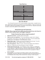
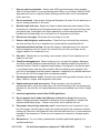
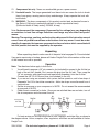
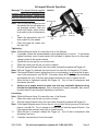
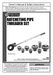
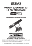
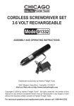
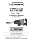
®
AIR Impact wrench
and
ratchet set
Model 92208
ASSEMBLY and OPERATIoN
INSTRUCTIONS
3491 Mission Oaks Blvd., Camarillo, CA 93011
Visit our Web site at http://www.harborfreight.com
To prevent serious injury,
Read and understand all warnings
and instructions before use.
Copyright© 2004 by Harbor Freight Tools®. All rights reserved. No portion
of this manual or any artwork contained herein may be reproduced in any shape
or form without the express written consent of Harbor Freight Tools.
For technical questions and replacement parts, please call 1-800-444-3353
REV 11h
Specifications
1
Air Inlet /4”-18 NPT (All tools)
Maximum Operating Pressure 90 PSI (All tools)
Air Ratchet
Dimensions
1-5/8” D x 10-3/8” L
Drive Size
3/8” Sq.
Maximum Torque Output
50 Ft. Lbs.
Air Consumption
4 CFM
No Load RPM
150 (Reversible)
Impact Wrench
Dimensions
2-3/4” W x 7-1/4” L x 8” H
Drive Size
1/2” Sq.
Maximum Torque Output
240 Ft. Lbs.
Air Consumption
4 CFM
RPM
6,500 (Reversible)
BPM
1,020
Save This Manual
You will need the manual for the safety warnings and precautions, assembly instructions, operating and maintenance procedures, parts list and diagram. Keep your invoice with
this manual. Write the invoice number on the inside of the front cover. Keep the manual and
invoice in a safe and dry place for future reference.
Safety Warnings and Precautions
WARNING: When using tools, basic safety precautions should always be followed to
reduce the risk of personal injury and damage to equipment.
Read all instructions before using this product!
1.
Keep work area clean. Cluttered areas invite injuries.
2.
Observe work area conditions. Do not use machines or power tools in damp or
wet locations. Don’t expose to rain. Keep work area well lit. Do not use electrically
powered tools in the presence of flammable gases or liquids.
3.
Keep children away. Children must never be allowed in the work area. Do not let
them handle machines, tools, extension cords, or air hoses.
4.
Store idle equipment. When not in use, tools must be stored in a dry location to
inhibit rust. Always lock up tools and keep out of reach of children.
5.
Use the right tool for the job. Do not attempt to force a small tool or attachment
to do the work of a larger industrial tool. There are certain applications for which this
tool was designed. It will do the job better and more safely at the rate for which it was
intended. Do not modify this tool and do not use this tool for a purpose for which it
was not intended.
6.
Dress properly. Do not wear loose clothing or jewelry as they can be caught in
moving parts. Protective, electrically nonconductive clothes and nonskid footwear are
recommended when working. Wear restrictive hair covering to contain long hair.
SKU 92208
For technical questions, please call 1-800-444-3353.
Page 2
7.
Use eye and ear protection. Always wear ANSI approved impact safety goggles.
Wear a full face shield if you are producing metal filings or wood chips. Wear an ANSI
approved dust mask or respirator when working around metal, wood, and chemical
dusts and mists.
8.
Do not overreach. Keep proper footing and balance at all times. Do not reach over or
across running machines or air hoses.
9.
Maintain tools with care. Keep tools clean for better and safer performance. Follow
instructions for lubricating and changing accessories. Inspect tool cords and air hoses
periodically and, if damaged, have them repaired by an authorized technician. The
handles must be kept clean, dry, and free from oil and grease at all times.
10. Disconnect air supply. Disconnect air hose when not in use.
11. Remove adjusting keys and wrenches. Check that keys and adjusting wrenches
are removed from the tool or machine work surface before connecting the tool.
12. Avoid unintentional starting. Be sure the trigger is released when not in use and
before connecting to the air source. Do not carry any tool with your finger on the
trigger, whether it is connected or not.
13. Stay alert. Watch what you are doing, use common sense. Do not operate any tool
when you are tired.
14. Check for damaged parts. Before using any tool, any part that appears damaged
should be carefully checked to determine that it will operate properly and perform its
intended function. Check for alignment and binding of moving parts; any broken parts
or mounting fixtures; and any other condition that may affect proper operation. Any
part that is damaged should be properly repaired or replaced by a qualified technician.
Do not use the tool if the trigger does not operate properly.
15. Guard against electric shock. Prevent body contact with grounded surfaces such as
pipes, radiators, ranges, and refrigerator enclosures.
16. Replacement parts and accessories. When servicing, use only identical
replacement parts. Use of any other parts will void the warranty. Only use accessories
intended for use with this tool. Approved accessories are available from Harbor Freight
Tools.
17. Industrial applications must follow OSHA guidelines.
18. Do not operate tool if under the influence of alcohol or drugs. Read warning
labels if taking prescription medicine to determine if your judgement or reflexes are
impaired while taking drugs. If there is any doubt, do not operate the tool.
19. Use proper size and type extension cord. If an extension cord is required, it must
be of the proper size and type to supply the correct current to the compressor without
heating up. Otherwise, the extension cord could melt and catch fire, or cause electrical
damage to the compressor. Check your air compressor’s manual for the appropriate
size cord.
20. Maintenance. For your safety, maintenance should be performed regularly by a
qualified technician.
SKU 92208
For technical questions, please call 1-800-444-3353.
Page 3
21. Compressed air only. Never use combustible gas as a power source.
22. Use both hands. The torque generated from these tools can cause the tools to break
free of your grasp, causing serious injury and damage. Always operate the tools with
both hands.
23. WARNING: The brass components of this product contain lead, a chemical known to
the State of California to cause birth defects (or other reproductive harm).
(California Health & Safety code § 25249.5, et seq.)
Note: Performance of the compressor (if powered by line voltage) may vary depending
on variations in local line voltage. Extension cord usage may also affect tool performance.
Warning: The warnings, cautions, and instructions discussed in this instruction manual
cannot cover all possible conditions and situations that may occur. It must be understood by the operator that common sense and caution are factors which cannot be built
into this product, but must be supplied by the operator.
Unpacking
When unpacking, check to make sure all of the parts listed on pages 10-13 are included.
If any parts are missing or broken, please call Harbor Freight Tools at the number on the cover
of this manual as soon as possible.
Operation
Note: The directions below apply to both tools.
1.
You will need to prepare a 1/4” air connector (not included) to connect to the Air Inlet on
back of the air tool’s handle. First, remove the plug from the Air Inlet. Then, wrap the
1/4” air connector with pipe thread seal tape before threading it into the Air Inlet.
Connect the 3/8” ID Air Source Hose (not included) to the tool.
Note: If you are not using an automatic oiler system, before operation, add a few drops of
Pneumatic Tool Oil to the airline connection. Add a few drops more after each hour of
continual use.
2.
Set the air pressure on your compressor to 90 PSI. Do not exceed the recommended
air pressure of 90 PSI.
3.
Check the air connection for leaks. Once you are satisfied there are no leaks, turn off
the air compressor and disconnect the tool.
Air Tool
1/4”-NPT
For best service you should incorporate an oiler, regulator, and inline filter, as shown in
the diagram above. Hoses, couplers, oilers, regulators, and filters are all available at Harbor
Freight Tools.
SKU 92208
For technical questions, please call 1-800-444-3353.
Page 4
Air Impact Wrench Operation
Warning!! This Impact Wrench supplies FIGURE 1
powerful torque and is designed to be
operated with two hands. Failure to operate the Impact Wrench with two hands
may result in serious injury.
Air Inlet (10)
Note: Turn off your air compressor and
disconnect the air hose when you
are changing sockets. After you
attach the socket, attach the air
hose and turn the air compressor
on.
Air Regulator
1.
Select the appropriate size 1/2”
(12)
drive socket for your needs.
2.
Push and snap the socket onto
the Anvil (18).
Screw (40)
A n v i l
(18)
Tr i g g e r
(4)
Reverse
Valve (3)
Tightening
Note: Slide the Reverse Valve (3) toward the front of the Wrench.
3.
If available, check the recommended torque specification for the nut. To accurately
tighten hardware, use a torque wrench (not included) to tighten the nut to the proper
setting instead of the impact wrench.
4.
Tighten the nut as tight as you can by hand.
5.
Place the socket over the nut you wish to tighten.
6.
Grip the Impact Wrench firmly with two hands and gently squeeze the Trigger (4).
Note: With the Trigger (4) released, fine tune the air flow with the Air Regulator (12) knob.
Note: If the Impact Wrench cannot tighten the nut to your satisfaction, do not raise the air pressure on the compressor over 90 PSI. Pressures above 90 PSI will strip the workpiece
and damage the tool. Use other appropriate methods and tools to tighten the nut.
7.
When the nut is tightened, release the Trigger (4). Turn off the air compressor and
disconnect the hose.
8.
Always use a torque wrench to make sure that any nuts/bolts tightened using
this tool are tightened properly. Due to the nature of impact wrenches, they cannot
be relied upon to ensure proper tightening of nuts/bolts.
Loosening
Note: Slide the Reverse Valve (3) toward the rear of the Wrench.
9.
Place the socket over the nut you wish to loosen.
10. Grip the Impact Wrench firmly with two hands and gently squeeze the Trigger (4).
Note: If the Impact Wrench cannot loosen the nut, do not raise the air pressure on the compressor over 90 PSI. Do not attempt to loosen the nut with the Impact Wrench. Use
other appropriate methods and tools to loosen the nut.
11. When the nut is loosened, release the Trigger (4). Turn off the air compressor and
disconnect the hose.
12. If needed, remove the nut from the socket.
SKU 92208
For technical questions, please call 1-800-444-3353.
Page 5
Air Ratchet Operation
FIGURE 2
Reverse Switch (21a)
Air Inlet
Trigger (35a)
Anvil
(22a)
Warning! Do not use a “cheater” or other extension to increase torque for this tool. Do
not exceed the maximum torque rating on this tool.
Warning! Disconnect the Ratchet from the air source when attaching and removing
sockets. There is no safety lock mechanism on this tool; always disconnect from the
air source when not in use.
1.
2.
3.
Refer to the photograph above.
Attach a 3/8” drive socket to the Ratchet Anvil (22a).
By following the directions on page 4, attach the Ratchet to the air source hose.
Gently press the Trigger (35a) to activate the Ratchet. Do not force the unit; allow it to
do the work for you. To change direction (loosen vs. tighten), stop the tool and move
it away from the workpiece, then turn the Reverse Switch (21a).
4.
To adjust the torque, readjust the air pressure by changing the setting on the compressor.
Do not exceed the maximum air pressure of 90 PSI for this tool at any time.
5.
When you are finished working, turn off the compressor and disconnect the air source
hose.
Warning! There may still be air in the Ratchet. Squeeze the Trigger (35a) and activate the
Ratchet to expel any air still inside the tool.
6.
Remove the socket.
Maintenance
1.
2.
3.
4.
5.
Make sure the air tool is disconnected from the air hose before attempting any maintenance.
If you are not using an automatic oiler system, put a few drops of pneumatic tool oil
through the air line before and after each use. During use, add a few drops every
hour.
Wipe the Tool down with a lint free cloth after each use.
Make sure the tool’s body, especially the Anvil (22a / 18), is clear of dirt and debris. If
possible, spray it with compressed air before each use.
For the Impact Wrench:
Apply a few drops of oil to the oil entry port before each use. Remove the Screw (40),
add the oil, then replace the Screw (40) - see FIGURE 1, page 5.
SKU 92208
For technical questions, please call 1-800-444-3353.
Page 6
Air Impact Wrench Assembly Diagram
Parts List
Part
Description
Part
Description
Part
Description
1
Housing
16
Screw
31
Spring
2
Valve Sleeve
17
Anvil Bushing
32
Pin
3
Reverse Valve
18
Anvil (1/2”)
33
Rear Gasket
7
4
Trigger
19
Hammer Cage
34
Rear Cover
1
5
Pin
20
Hammer Pin
35
Washer
9
6
Bushing
21
Hammer Dog
36
Screw
5
7
Valve Stem
22
Drive Cam
37
Rubber Cover
11
8
Steel Ball
23
Cylinder Pin
38
Exhaust Deflector
3
9
Spring
24
Cylinder
39
Screw
13
10
Air Inlet
25
Rotor
40
Screw
7
11
Screen
26
Rotor Blade
41
Anvil Collar
15
12
Air Regulator
27
Front End Plate
42
O-Ring
1” Impact Socket
13
O-Ring
28
Ball Bearing
43
Rubber Strap
Blowmold Case
14
Spring
29
Rear End Plate
44
Screw
15
Oil Seal
30
Pin
45
Brass Silencer
Accessories
(not shown above)
3
/8” to 1/2” Adapter
/16” Impact Socket
/2” Impact Socket
/16” Impact Socket
/8” Impact Socket
/16” Impact Socket
/4” Impact Socket
/16” Impact Socket
/8” Impact Socket
/16” Impact Socket
NOTE: Some parts are listed and shown for illustration purposes only and are
not available individually as replacement parts.
SKU 92208
For technical questions, please call 1-800-444-3353.
Page 7
Assembly Diagram A - Air Ratchet
Note:All part numbers referred
to on this diagram are indicated with a suffix of a. For
example, part 1a refers to
part 1 on this diagram.
Parts List A
Part
Description
Qty.
Part
Description
Qty.
Part
Description
Qty.
1a
Housing
1
14a
Idler Gear Pin
3
26a
Ratchet Pawl
1
2a
Rear Bearing
1
15a
Idler Gear Plate
1
27a
Pin
1
3a
Rear Plate
1
16a
Bushing
1
28a
Washer
1
4a
Steel Ball
1
17a
Ratchet Housing
1
29a
Retaining Ring
1
5a
Rotor
1
18a
Shaft
1
30a
Valve Plug
1
6a
Rotor Blade
4
19a
Drive Bushing
1
31a
O-Ring
1
7a
Cylinder
1
20a
Ratchet Yoke
1
32a
Spring
1
8a
Front Plate
1
21a
Reverse Switch
1
33a
Valve Stem Bushing
1
9a
Front Bearing
1
22a
Ratchet Anvil
1
34a
Valve Stem
1
10a
Washer
1
23a
Wave Washer
1
35a
Trigger
1
11a
Thread Ring
Gear
1
24a
Spring
1
36a
Spring Pin
1
12a
Clamp Nut
1
25a
Lock Pin
1
37a
Bushing
1
13a
Idler Gear
3
SKU 92208
For technical questions, please call 1-800-444-3353.
Page 8
90 Day Warranty
Harbor Freight Tools Co. makes every effort to assure that its products meet high quality
and durability standards, and warrants to the original purchaser that this product is free from
defects in materials and workmanship for the period of 90 days from the date of purchase. This
warranty does not apply to damage due directly or indirectly, to misuse, abuse, negligence or
accidents, repairs or alterations outside our facilities, criminal activity, improper installation,
normal wear and tear, or to lack of maintenance. We shall in no event be liable for death,
injuries to persons or property, or for incidental, contingent, special or consequential damages
arising from the use of our product. Some states do not allow the exclusion or limitation of
incidental or consequential damages, so the above limitation of exclusion may not apply to
you. This warranty is expressly in lieu of all other warranties, express or implied, including the
warranties of merchantability and fitness.
To take advantage of this warranty, the product or part must be returned to us with
transportation charges prepaid. Proof of purchase date and an explanation of the complaint
must accompany the merchandise. If our inspection verifies the defect, we will either repair or
replace the product at our election or we may elect to refund the purchase price if we cannot
readily and quickly provide you with a replacement. We will return repaired products at our
expense, but if we determine there is no defect, or that the defect resulted from causes not
within the scope of our warranty, then you must bear the cost of returning the product.
This warranty gives you specific legal rights and you may also have other rights which vary
from state to state.
PLEASE READ THE FOLLOWING CAREFULLY
The manufacturer and/or distributor has provided the parts diagrams in this
manual as a reference tool only. Neither the manufacturer nor distributor makes
any representation or warranty of any kind to the buyer that he or she is qualified
to make any repairs to the product or that he or she is qualified to replace any
parts of the product. In fact, the manufacturer and/or distributor expressly states
that all repairs and parts replacements should be undertaken by certified and
licensed technicians and not by the buyer. The buyer assumes all risk and liability
arising out of his or her repairs to the original product or replacement parts
thereto, or arising out of his or her installation of replacement parts thereto.
REV 11h
SKU 92208
For technical questions, please call 1-800-444-3353.
Page 9