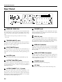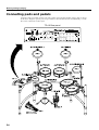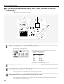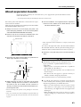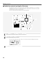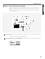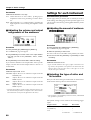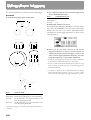
1
® We’d like to take a moment to thank you for purchasing the Roland Percussion Sound Module TD-10. Before using this unit, carefully read the sections entitled: “IMPORTANT SAFETY INSTRUCTIONS” (p. 2), “USING THE UNIT SAFELY” (p. 3, 4), and “IMPORTANT NOTES” (p. 17). These sections provide important information concerning the proper operation of the unit. Additionally, in order to feel assured that you have gained a good grasp of every feature provided by your new unit, this manual should be read in its entirety. The manual should be saved and kept on hand as a convenient reference. Copyright © 1997 ROLAND CORPORATION All rights reserved. No part of this publication may be reproduced in any form without the written permission of ROLAND CORPORATION. CAUTION RISK OF ELECTRIC SHOCK DO NOT OPEN ATTENTION: RISQUE DE CHOC ELECTRIQUE NE PAS OUVRIR CAUTION: TO REDUCE THE RISK OF ELECTRIC SHOCK, DO NOT REMOVE COVER (OR BACK). NO USER-SERVICEABLE PARTS INSIDE. REFER SERVICING TO QUALIFIED SERVICE PERSONNEL. The lightning flash with arrowhead symbol, within an equilateral triangle, is intended to alert the user to the presence of uninsulated “dangerous voltage” within the product’s enclosure that may be of sufficient magnitude to constitute a risk of electric shock to persons. The exclamation point within an equilateral triangle is intended to alert the user to the presence of important operating and maintenance (servicing) instructions in the literature accompanying the product. INSTRUCTIONS PERTAINING TO A RISK OF FIRE, ELECTRIC SHOCK, OR INJURY TO PERSONS. IMPORTANT SAFETY INSTRUCTIONS SAVE THESE INSTRUCTIONS WARNING - When using electric products, basic precautions should always be followed, including the following: 1. Read all the instructions before using the product. 2. Do not use this product near water — for example, near a bathtub, washbowl, kitchen sink, in a wet basement, or near a swimming pool, or the like. 3. This product should be used only with a cart or stand that is recommended by the manufacturer. 4. This product, either alone or in combination with an amplifier and headphones or speakers, may be capable of producing sound levels that could cause permanent hearing loss. Do not operate for a long period of time at a high volume level or at a level that is uncomfortable. If you experience any hearing loss or ringing in the ears, you should consult an audiologist. 5. The product should be located so that its location or position does not interfere with its proper ventilation. 6. The product should be located away from heat sources such as radiators, heat registers, or other products that produce heat. 7. The product should be connected to a power supply only of the type described in the operating instructions or as marked on the product. 8. The power-supply cord of the product should be unplugged from the outlet when left unused for a long period of time. 9. Care should be taken so that objects do not fall and liquids are not spilled into the enclosure through openings. 10.The product should be serviced by qualified service personnel when: A. The power-supply cord or the plug has been damaged; or B. Objects have fallen, or liquid has been spilled into the product; or C. The product has been exposed to rain; or D. The product does not appear to operate normally or exhibits a marked change in performance; or E. The product has been dropped, or the enclosure damaged. 11.Do not attempt to service the product beyond that described in the user-maintenance instructions. All other servicing should be referred to qualified service personnel. For the USA GROUNDING INSTRUCTIONS This product must be grounded. If it should malfunction or breakdown, grounding provides a path of least resistance for electric current to reduce the risk of electric shock. This product is equipped with a cord having an equipment-grounding conductor and a grounding plug. The plug must be plugged into an appropriate outlet that is properly installed and grounded in accordance with all local codes and ordinances. DANGER: Improper connection of the equipment-grounding conductor can result in a risk of electric shock. Check with a qualified electrician or serviceman if you are in doubt as to whether the product is properly grounded. Do not modify the plug provided with the product — if it will not fit the outlet, have a proper outlet installed by a qualified electrician. For the U.K. WARNING: THIS APPARATUS MUST BE EARTHED IMPORTANT: THE WIRES IN THIS MAINS LEAD ARE COLOURED IN ACCORDANCE WITH THE FOLLOWING CODE. GREEN-AND-YELLOW: EARTH, BLUE: NEUTRAL, BROWN: LIVE As the colours of the wires in the mains lead of this apparatus may not correspond with the coloured markings identifying the terminals in your plug, proceed as follows: The wire which is coloured GREEN-AND-YELLOW must be connected to the terminal in the plug which is marked by the letter E or by the safety earth symbol or coloured GREEN or GREEN-AND-YELLOW. The wire which is coloured BLUE must be connected to the terminal which is marked with the letter N or coloured BLACK. The wire which is coloured BROWN must be connected to the terminal which is marked with the letter L or coloured RED. The product which is equipped with a THREE WIRE GROUNDING TYPE LINE PLUG must be grounded. 2 USING THE UNIT SAFELY Used for instructions intended to alert the user to the risk of death or severe injury should the unit be used improperly. Used for instructions intended to alert the user to the risk of injury or material damage should the unit be used improperly. * Material damage refers other adverse effects respect to the home furnishings, as well animals or pets. to damage or caused with and all its to domestic The symbol alerts the user to important instructions or warnings.The specific meaning of the symbol is determined by the design contained within the triangle. In the case of the symbol at left, it is used for general cautions, warnings, or alerts to danger. The symbol alerts the user to items that must never be carried out (are forbidden). The specific thing that must not be done is indicated by the design contained within the circle. In the case of the symbol at left, it means that the unit must never be disassembled. The ● symbol alerts the user to things that must be carried out. The specific thing that must be done is indicated by the design contained within the circle. In the case of the symbol at left, it means that the powercord plug must be unplugged from the outlet. • Before using this unit, make sure to read the instructions below, and the Owner’s Manual. ........................................................................................................... • Protect the unit from strong impact. (Do not drop it!) ........................................................................................................... • Do not open or perform any internal modifications on the unit. (The only exception would be where this manual provides specific instructions which should be followed in order to put in place userinstallable options; see p. 43.) ........................................................................................................... • Do not force the unit’s power-supply cord to share an outlet with an unreasonable number of other devices. Be especially careful when using extension cords—the total power used by all devices you have connected to the extension cord’s outlet must never exceed the power rating (watts/amperes) for the extension cord. Excessive loads can cause the insulation on the cord to heat up and eventually melt through. ........................................................................................................... • When using the unit with a rack or stand recommended by Roland, the rack or stand must be carefully placed so it is level and sure to remain stable. If not using a rack or stand, you still need to make sure that any location you choose for placing the unit provides a level surface that will properly support the unit, and keep it from wobbling. ........................................................................................................... • Use only the attached power-supply cord. ........................................................................................................... • Avoid damaging the power cord. Do not bend it excessively, step on it, place heavy objects on it, etc. A damaged cord can easily become a shock or fire hazard. Never use a power cord after it has been damaged. ........................................................................................................... • In households with small children, an adult should provide supervision until the child is capable of following all the rules essential for the safe operation of the unit. ........................................................................................................... • Before using the unit in a foreign country, consult with your dealer, or qualified Roland service personnel. ........................................................................................................... • Always turn the unit off and unplug the power cord before attempting installation of the circuit board (WAVE & SYSTEM EXPANSION BOARD TDW series; p. 43). ........................................................................................................... • Do not put anything that contains water (e.g., flower vases) on this unit. Also, avoid the use of insecticides, perfumes, alcohol, nail polish, spray cans, etc., near the unit. Swiftly wipe away any liquid that spills on the unit using a dry, soft cloth. ........................................................................................................... 3 USING THE UNIT SAFELY • Always grasp only the plug on the power-supply cord when plugging into, or unplugging from, an outlet or this unit. ........................................................................................................... • Try to prevent cords and cables from becoming entangled. Also, all cords and cables should be placed so they are out of the reach of children. ........................................................................................................... • Never climb on top of, nor place heavy objects on the unit. ........................................................................................................... • Never handle the power cord or its plugs with wet hands when plugging into, or unplugging from, an outlet or this unit. ........................................................................................................... • Before moving the unit, disconnect the power plug from the outlet, and pull out all cords from external devices. ........................................................................................................... • Before cleaning the unit, turn off the power and unplug the power cord from the outlet (p. 27). ........................................................................................................... • Whenever you suspect the possibility of lightning in your area, pull the plug on the power cord out of the outlet. ........................................................................................................... • Install only the specified circuit board(s) (WAVE & SYSTEM EXPANSION BOARD TDW series). Remove only the specified screws (p. 43). ........................................................................................................... 4 How to read this owner’s manual This owner’s manual is organized as follows. Quick Start This section is intended for those using the TD-10 for the first time, and explains how to use various functions in a simple way. Please read Quick Start and follow along by actually operating the TD10. This will help you understand most of what you need to know for basic operations. If you find unfamiliar words or terms, refer to the “Glossary” on p. 169. More advanced ways of using the TD10, or details of other operations are explained the Reference section. Advanced Use This section explains all functions of the TD-10 in detail and is divided into specific parts. Basic panel operations and displays are covered in the Quick Start. The Advanced Use section assumes you already understand basic procedures, so if anything’s unclear, refer to the “Quick Start.” Chapter 1. Overview of the TD-10 V-drums This chapter explains the concept of the TD-10 and how it is organized. Read this chapter in order to understand what the TD-10 is. Chapters 2–5. Functions for creating sound If you wish to learn more about the sound creation possibilities introduced in the “Quick Start,” refer to chapters 2–5. Chapter 6. Using a sequencer and related functions This chapter explains sequencer functions such as performance, recording, click settings, and pattern editing. Chapter 7. Settings for the entire TD-10 This chapter explains settings that affect the entire TD-10, such as adjusting the overall sound, saving data to a memory card etc. Chapters 8 and 9. Convenient functions and how to use them These chapters explain how to use pads or pedals for pattern play back, and other functions, and about time-saving operations such as copy and help. Chapter 10. Functions using MIDI This chapter explains how to use MIDI—whether it be for saving data to an external device, or for using the TD-10 as a sound module. Appendices If you run into problems, refer to “Troubleshooting” to make sure that the settings are correct. If an error message appears during operation, refer to “Message/Error Message List” and take appropriate action. This section also provides information related to sound editing, MIDI, various lists, and the MIDI implementation charts. * The display screens printed in this owner’s manual are based on the factory settings. However, please be aware that in some cases they may differ from the actual factory settings. 5 Contents IMPORTANT SAFETY INSTRUCTIONS ............................................................................2 USING THE UNIT SAFELY.................................................................................................3 How to read this owner’s manual ........................................................................................5 Features ............................................................................................................................12 Front and rear panel..........................................................................................................14 Important notes .................................................................................................................17 About button operations and the screen displays .............................................................18 Quick Start ..............................21 Before you begin playing..........................22 Mounting the TD-10 to the stand.......................................................................................22 Connect your audio system or amp...................................................................................23 Connecting pads and pedals.............................................................................................24 Turning on the power ........................................................................................................26 To turn the power off ... .....................................................................................................................27 Listening to the internal demo playback ............................................................................28 Specify the pads that the TD-10 will use ...........................................................................29 If you have purchased the “V-Basic Kit” or “V-Standard Kit” ....................................................29 If you have purchased the PD-5, PD-7, PD-9, PD-100 or PD-120 individually .........................30 Using triggers on an acoustic drum to play the TD-10 .................................................................33 Check the settings.............................................................................................................34 For a better performance ..........................35 Concerning the performance & expressiveness of the pads.............................................35 Rim shots..............................................................................................................................................35 Choking ................................................................................................................................................35 Positional sensing ...............................................................................................................................36 Playing with brushes..........................................................................................................................36 Hi-hat control pedal ...........................................................................................................................36 TD-10 operating procedure ...............................................................................................37 Adjusting the volume.........................................................................................................................37 Selecting a drum kit............................................................................................................................38 Adjusting the sensitivity of a pad.....................................................................................................39 Master equalizer..................................................................................................................................40 Effect on/off ........................................................................................................................................41 Help function.......................................................................................................................................42 About expansion boards....................................................................................................43 À propos des cartes d’extension .......................................................................................44 (French language for Canadian Safety Standard) Troubleshooting connections and settings ........................................................................45 Features of the preset drum kits................47 How sounds are created on the V-drums..........................................................................47 No.36: 70’s Rock drum kit .................................................................................................48 No.37: Brush Kit ................................................................................................................50 No.38: Electronic drum kit .................................................................................................52 6 Contents Modifying a drum kit ................................54 [INST]: Creating drum sounds ..........................................................................................55 Selecting an instrument......................................................................................................................55 Modify the material and depth of the body....................................................................................56 Change the material and tuning of the head ..................................................................................58 Adjust the muffling (muting) and snare strainer tension .............................................................60 [STUDIO]: Adjusting the acoustics of the room.................................................................62 Decide “where” the drums are played ............................................................................................63 Change the size of the room..............................................................................................................64 [CONTROL ROOM]: Adding finishing touches to the sound.............................................65 Using the equalizer to modify the sound........................................................................................65 Adjusting the volume balance of the instruments .........................................................................67 Examples and convenient tips ...................68 Perform with the on-board sequencer ...............................................................................68 Playing back a preset pattern ............................................................................................................68 Play the pads along with a preset pattern.......................................................................................69 Drum Kit Chain—Selecting drum kits in the desired order ................................................70 Using a foot switch to select kits .......................................................................................72 Using a pad to playback patterns ......................................................................................72 Using headphones to hear the click sound .......................................................................73 Using the TD-10 as a MIDI sound module ........................................................................74 Advanced Use .........................75 Chapter 1. Overview of the TD-10 V-drums.......76 How the V-drums system is organized..............................................................................76 How to select pads ............................................................................................................77 Using pads to select the pad/sound for editing ............................................................................77 Using the TD-10 to select the pad/sound for editing....................................................................77 Chapter 2. Settings for the entire drum kit ....78 Selecting a kit ....................................................................................................................78 Selecting kits from the list display .....................................................................................78 Naming a kit ......................................................................................................................78 Making settings for brush performance .............................................................................79 Effect switches for the entire kit.........................................................................................79 7 Contents Chapter 3. Instrument settings ..................80 Selecting an instrument.....................................................................................................80 Selecting instruments from the list display ........................................................................80 Editing an acoustic drum kit (V-EDIT) ..............................................................................81 Selecting the shell material ................................................................................................................81 Changing the shell depth...................................................................................................................82 Selecting the head material................................................................................................................82 Tuning the head ..................................................................................................................................82 Muffling settings (muting) ................................................................................................................83 Adjusting the snare strainer tension ................................................................................................83 Editing an electronic drum kit (V-EDIT) .............................................................................84 Editing a TR-808/909 (V-EDIT) .........................................................................................85 Editing hi-hat, cymbals and percussion.............................................................................86 Chapter 4. Studio settings .........................87 Settings for the entire drum kit ..........................................................................................87 Selecting the studio/room.................................................................................................................87 Changing the size of the room ..........................................................................................................87 Changing the wall material ...............................................................................................................87 Selecting the ambience mike location ..............................................................................................87 Adjusting the volume and output assignments of the ambience ................................................88 Settings for each instrument..............................................................................................88 Adjusting the amount of ambience ..................................................................................................88 Selecting the type of mike and its location......................................................................................88 Settings for each group .....................................................................................................89 Adjusting the amount of ambience send level for each group ....................................................89 Chapter 5. Control room settings ...............90 Settings for each instrument..............................................................................................90 Adjusting volume (level) ...................................................................................................................90 Adjusting pan (stereo location).........................................................................................................90 Adjusting effect send level ................................................................................................................90 Selecting output assignments............................................................................................................91 Controlling variations in volume (Compressor) ............................................................................91 Customizing the tone (Equalizer).....................................................................................................92 Settings for the entire drum kit ..........................................................................................93 Adjusting effect Return level ............................................................................................................93 Selecting the type of effect .................................................................................................................93 Editing the effects ...............................................................................................................................94 Settings for an entire group ...............................................................................................96 Adjusting effect send level for an entire group..............................................................................96 Adjusting the volume by group .......................................................................................................96 8 Contents Chapter 6. Sequencer................................97 Basic sequencer operation................................................................................................97 Using Preset Patterns .........................................................................................................................97 Setting the tempo ..............................................................................................................97 Setting the tempo for each pattern ...................................................................................................97 Temporarily changing the tempo of the currently-playing pattern............................................97 Playback functions ............................................................................................................98 Selecting a pattern...............................................................................................................................98 Selecting patterns from the list .........................................................................................................98 Selecting how a pattern will playback.............................................................................................98 Click settings .....................................................................................................................99 Click on/off and volume settings ....................................................................................................99 Setting the tempo ................................................................................................................................99 Setting the time signature and click interval ..................................................................................99 Selecting the click sound..................................................................................................................100 Using ambience .................................................................................................................................100 Using effects ......................................................................................................................................100 Adjusting the pan (stereo location) ................................................................................................100 Selecting the output destination .....................................................................................................100 Recording ........................................................................................................................101 Basic recording procedure...............................................................................................................101 The Rehearsal function ....................................................................................................................102 Using a count-in ................................................................................................................................102 Start recording the moment that you strike a pad .......................................................................102 Correcting timing as you record (Quantize).................................................................................103 Importing data from another sequencer into the TD-10 .............................................................103 Editing a pattern ..............................................................................................................103 Naming a pattern..............................................................................................................................103 Erasing a pattern ...............................................................................................................................104 Erasing selected measures of a pattern..........................................................................................104 Copying a pattern .............................................................................................................................104 Copying selected measures of a pattern........................................................................................105 Clearing a pattern .............................................................................................................................105 Clearing selected measures of a pattern........................................................................................105 Connecting two patterns..................................................................................................................106 Settings for part instruments ...........................................................................................106 Adjusting the master tuning ...........................................................................................................106 Instrument selection and settings for each part ...........................................................................106 Mixer settings for each part.............................................................................................................107 Muting a specific part.......................................................................................................................107 9 Contents Chapter 7. Settings for the entire TD-10...108 Changing output assignment for audio received by the MIX IN jack...............................108 Specifying the type of pad ...............................................................................................108 Basic settings for the trigger parameters (BASIC) ..........................................................109 Detailed settings for the trigger parameters (ADVNCD)..................................................111 The order in which trigger parameters should be set when using drum triggers.............112 Adjusting the brightness of the display............................................................................113 Setting the master equalizer............................................................................................113 Saving data to a memory card ........................................................................................114 Loading data from a memory card ..................................................................................115 Automatically switching the display (Note Chase)...........................................................115 Chapter 8. Convenient functions ..............116 Selecting kits in the desired order (Drum Kit Chain) .......................................................116 Specifying a Drum Kit Chain ..........................................................................................................116 Naming a Drum Kit Chain ..............................................................................................................116 Copying ...........................................................................................................................117 The UNDO function .........................................................................................................117 Getting help .....................................................................................................................118 Specifying how the Preview button functions ..................................................................118 Chapter 9. Operations using pads and foot switches ..........................................119 Using pads to play patterns (Pad Pattern) ......................................................................119 Using pads to perform button operations (Pad Switch) ..................................................119 Using foot switches to perform button operations (Foot Switch) .....................................120 Chapter 10. Functions using MIDI ............121 Saving/Loading data to/from an external device (Bulk Dump) ........................................121 Saving data ........................................................................................................................................121 Loading saved data to the TD-10....................................................................................................121 Setting the Device ID—Transmitting saved data to two or more TD-10 units........................122 Using pads to play an external MIDI sound module........................................................122 Selecting the note number transmitted by each pad ...................................................................122 Setting the Gate Time .......................................................................................................................123 Setting the MIDI channel .................................................................................................................123 Using the TD-10 with the Roland SPD-11.......................................................................123 MIDI settings for the entire TD-10 ...................................................................................124 Setting the MIDI channels for each Part........................................................................................124 Turning off Local Control................................................................................................................124 Disabling reception or transmission of Program Changes.........................................................124 Reducing the amount of data transmitted by the FD-7 (Pedal Data Thin) ..............................124 Using the TD-10 as a sound module...............................................................................125 Setting the instrument for each part ..............................................................................................125 Adjusting the mixer settings for each part....................................................................................125 Regarding note numbers for the drum kit sounds ......................................................................125 Using the percussion group ............................................................................................................126 Changing the kit number that is selected by a program change ...............................................128 10 Contents MIDI messages for detailed performance expressions ...................................................128 Messages for hi-hat control .............................................................................................................128 Messages for positional sensing (snare drum and ride cymbal only).......................................129 Synchronization with external MIDI devices....................................................................129 Appendices............................131 Troubleshooting...............................................................................................................132 Instruments that can be used with each trigger...............................................................136 Restoring the factory settings (INITIALIZE).....................................................................137 Message / error message list ..........................................................................................138 About MIDI ......................................................................................................................140 Using drum triggers .........................................................................................................142 Preset list.........................................................................................................................143 MIDI implementation .......................................................................................................154 MIDI implementation chart ..............................................................................................165 Specifications ..................................................................................................................168 Glossary ..........................................................................................................................169 Index of screen displays..................................................................................................173 Index................................................................................................................................176 * PinStripe is a registered trademark of Remo Inc. U.S.A. 11 Features ● Enhanced tonal quality and expressiveness that rivals acoustic drums The TD-10 features a newly developed modeling sound module that relies on COSM technology. The force and position of the hit are detected, providing sensitive and dynamic expression that is extremely close to that of acoustic drums. In addition, when PD-100 or PD-120 (optional) pads are used, you can enjoy excellent response when playing rolls. * COSM (Composite Object Sound Modeling) is a Roland technology which combines multiple sound modeling processes to create new sounds. * Positional detection is possible on snare drums and ride cymbals. ● With 600 drum sounds and 54 backing instrument provided A rich array of instrumental sounds are provided, sufficient to cover all styles of music. ● A user interface comfortable for drummers You can create sounds much in the same way that you would using acoustic drums when you select a preferred drum head, tune it, and attach muffling (muting) material. With the large display, the use of graphics and icons to portray parameters being set and their meanings, operation is intuitive and easily understood. ● High-speed trigger response The triggering time (time delay from hitting the pad until you hear the sound) is faster than ever, allowing expressiveness and dynamics to be reproduced accurately. ● Twelve pads can be used simultaneously Since up to twelve pads can be used simultaneously, you can create large-scale setups bigger than ever before. This also gives you flexibility for extended applications, such as using pads as switches (Pad Switch) or for pattern playback (Pad Pattern). ● Simulate the entire process of actual recording By being able to choose drum materials, sizes, studio location, mike types and their settings, effects and mixer parameters, the TD-10 allows total flexibility for recording or live applications. All of these settings can be stored as part of a drum kit,for instant recall at any time. ● Perform using brushes If you use the PD-100 or PD-120 pads, you can play with brushes, something not possible with any previous electronic drum system. (Nylon brush only please!). ● Sound processing specially selected for drums For each instrument assigned to trigger inputs 1–10, individual two-band equalizers and compressors are provided. In addition,(in the control room) —there are digital effects: reverbs, flanger, chorus, delays, pitch shift delay, and phaser. A three-band equalizer is also provided for processing the sound at the MASTER OUT. Ambience(in the Studio) lets you choose WHERE the drums are being played. You can change the sound of that space by changing the material of the walls, size of the room and the position of the ambient mikes. There are individual ambience send levels for all instruments. 12 Features ● Functions and operations perfect for live performances The group faders on the front panel let you make quick changes as needed during performance. You can play drum kits in any desired order (Drum Kit Chain). The INC/DEC buttons are large enough to be pressed with a drum stick. (Don’t HIT them!) Another very useful function allows you to send the click sound ONLY to the headphones if desired. An audio input (stereo) for custom monitoring (MIX IN jack) is also provided. ● Easy-operation sequencer is built-in With easy, tape recorder-like operations, you can record or play back patterns. In addition to the drums, three backing parts can be added for ensemble practice or for creating backing patterns via MIDI keyboard, external sequencer etc. * Brush swish/sweeping and choke cannot be recorded. ● Previous models of pads can be used Previous pad models (PD-5, PD-7, PD-9), kick trigger units (KD-5, KD-7) and the hi-hat control pedal (FD-7) are all compatible. Also, the PD-7 and PD-9 allow positional sensing for the snare drum and ride cymbal. ● User Installable Expansion boards allow extended functionality WAVE & SYSTEM EXPANSION BOARD TDW series will bring more instruments and drum kits to the TD-10, and allows the system to be upgraded through Flash ROM. A memory card (M-512E) can be used to store all kits and patterns for the TD-10. ● Usable as a MIDI sound module Percussion groups are provided so these sounds can be accessed via MIDI as with a dedicated module, so in addition to sounds assigned to the 12 trigger inputs, a special note map for percussion allows 72 types of instruments to be accessed simultaneously. 13 Front and rear panel Front Panel 15 1 8 17 18 3 2 16 19 7 6 5 4 20 21 10 9 11 12 13 14 22 1 Trigger Indicator This will light when a trigger signal (signal produced when pad is struck) is received from a pad. It allows you to check whether the pad has been connected correctly. 2 LED Display Displays the number of the currently selected drum kit. 3 Graphic Display During performance, this indicates the drum kit name and other important information. During editing, various graphics and text relative to the editing process is indicated. * In this owner’s manual, this will be referred to simply as “the display.” 5 EXIT Button Press this button and you will return to the screen one level higher in the hierarchy. Repeated pressing takes you back to the “DRUM KIT” page. 6 TOOLS Button Provides access to functions such as Copy, Undo, and Help. (p. 42, 117) 7 CHAIN Button Lets you make Drum Kit Chain settings (a function that arranges drum kits in a desired order for successive selection) (p. 70, 116). 8 SETUP Button 4 F1-F4 Buttons These buttons change their function depending on the contents of the display. The lower part of the display will indicate the function of each button (p. 18). 14 Here you can make settings that affect the entire TD-10, such as trigger parameters and MIDI settings (p. 108). Front and rear panel 9 GROUP FADERS These allow you to adjust the volume of the kick, snare, hihat, other percussion instruments, backing instruments, and the click sound (p. 37). 10 SEQUENCER Here are the buttons that control sequencer functions (playback/recording of performance patterns) (p. 68, 97). 11 KIT Button Provides access to the basic display page used when playing the TD-10. 20 TRIG SELECT Use the lower two buttons to select the pad (trigger number) for which you wish to make settings. To select the rim of a pad, press the RIM button, then the RIM indicator is lit. If pads are connected to the TD-10, you can also select a pad by striking it. The PREVIEW button lets you audition the instrument that is assigned to the selected pad or the sound appearing in the display when editing a percussion group (p. 20). 21 PREVIEW Button 12 INST (Instrument) Button Used to audition an instrument. By using TRIG SELECT buttons to select a pad, you can play and edit sound even if no pads are connected to the TD-10. The button is velocity sensitive (p. 20). Provides access to the display page in which you can edit instruments (p. 55, 80). 22 INC Button, DEC Button Provides access to the display page where you can choose mike types, their positions, ambience types and ambient mike positions (p. 62, 87). These buttons are used to switch drum kits or to modify values. Pressing the INC button increases the value, and pressing the DEC button decreases it. Since these buttons are large, you can also use the tip of your drum stick to press them (p. 19). 14 CONTROL ROOM Button * Please be aware that hitting the buttons with a stick can cause malfunctions. 13 STUDIO Button Allows you to edit mixer, EQ, compressor and effect parameters (p. 65, 90). 15 MIX IN Knob This adjusts the volume of the device connected to the MIX IN jack. The sound from the MIX IN will be output from the MASTER out and/or the PHONES jack. 16 PHONES Knob Adjusts the headphone volume. Even when headphones are connected, sound will still be output from the various output jacks. 17 MASTER Knob Adjusts the volume of the MASTER OUT jacks. The volume of the PHONES jack is adjusted by the PHONES knob. 18 CURSOR Buttons Used to move the cursor in the display, or to access the next display page (p. 18). 19 VALUE Dial This dial has the same function as the INC and DEC buttons. Use this dial when you wish to make large changes in drum kit settings or edited values (p. 19). 15 Front and rear panel Rear Panel 33 28 32 31 34 23 27 29 25 30 26 24 23 MEMORY CARD Slot 29 PHONES Jack An M-512E memory card (optional) can be inserted into this slot. Each memory card can store all settings of the TD-10, such as drum kits and sequencer performance data, etc (p. 114). A pair of stereo headphones can be connected to this jack. Even if headphones are connected, sound will still be output from the OUTPUT jacks (p. 23). * The M-512E is the only memory card that can be used by the TD-10. 30 MIX IN Jack 24 TRIGGER INPUT Jacks Accept the pads or kick trigger units you want to connect to the TD-10. To connect a dual trigger type pad (PD-7, PD-9, PD-120), use a stereo cable (p. 24). 25 FOOT SWITCH Jack Accepts connection of an optional foot switch (FS-5U). A foot switch can be used to select kits and start/stop the sequencer, etc. Use a special PCS-31 cable (optional) (p. 72, 120). 26 HH CTRL Jack Accepts connection of a hi-hat control pedal (FD-7) (p. 36). 27 OUTPUT (MASTER) Jacks These jacks output the instrumental sounds of the TD-10, and are for connection to external audio devices or amps. If you are listening in mono, connect to only the MASTER L (MONO) jack (p. 23). This jack is used to connect a CD or cassette player, or as a custom monitoring input for live/recording performances. The sound that is input to this jack will be output from the MASTER out jacks and/or the PHONES jack (p. 108). 31 MIDI IN Connector Use this connector when you wish to use an external MIDI sequencer to play the sounds of the TD-10, or when loading TD-10 settings (bulk data) that were saved on an external device (p. 121). 32 MIDI OUT/THRU Connector Use this connector when you wish to use play sounds in an external MIDI sound module/sampler from the pads, or when you wish to transmit TD-10 settings (bulk data) to another MIDI device (p. 121). 33 POWER Switch This switch turns the power on/off (p. 26). 34 AC Inlet Connect the included AC power cable to this inlet (p. 23). 28 OUTPUT (DIRECT 1, 2, 3) Jacks The direct outs allow you to have more “separation,” over the total kit, and can be used for external effects etc. Ambience may also be sent from these outputs, but NOT the digital effects. Output assignments DIRECT 1, 2 or 3 jacks are found in the Control Room (p. 91). 16 Important notes In addition to the items listed under “IMPORTANT SAFETY INSTRUCTIONS” and “USING THE UNIT SAFELY” on pages 2–4, please read and observe the following: Power Supply ● Do not use this unit on the same power circuit with any device that will generate line noise (such as an electric motor or variable lighting system). ● Before connecting this unit to other devices, turn off the power to all units. This will help prevent malfunctions and/or damage to speakers or other devices. ● Placement ● ● Using the unit near power amplifiers (or other equipment containing large power transformers) may induce hum. To alleviate the problem, change the orientation of this unit; or move it farther away from the source of interference. ● This device may interfere with radio and television reception. Do not use this device in the vicinity of such receivers. ● Do not expose the unit to direct sunlight, place it near devices that radiate heat, leave it inside an enclosed vehicle, or otherwise subject it to temperature extremes. Excessive heat can deform or discolor the unit. ● ● ● Maintenance ● For everyday cleaning wipe the unit with a soft, dry cloth or one that has been slightly dampened with water. To remove stubborn dirt, use a cloth impregnated with a mild, non-abrasive detergent. Afterwards, be sure to wipe the unit thoroughly with a soft, dry cloth. ● Never use benzene, thinners, alcohol or solvents of any kind, to avoid the possibility of discoloration and/or deformation. Repairs and Data ● Please be aware that all data contained in the unit’s memory may be lost when the unit is sent for repairs. Important data should always be backed up on a RAM card/DATA card, in another MIDI device (e.g., a sequencer), or written down on paper (when possible). During repairs, due care is taken to avoid the loss of data. However, in certain cases (such as when circuitry related to memory itself is out of order), we regret that it may not be possible to restore the data, and Roland assumes no liability concerning such loss of data. Memory Backup ● This unit contains a battery which powers the unit’s memory circuits while the main power is off. When this battery becomes weak, the message shown below will appear in the display. Once you see this message, have the battery replaced with a fresh one as soon as possible to avoid the loss of all data in memory. To have the battery replaced, consult with your dealer, or qualified Roland service personnel. “Backup Battery Low !” Additional Precautions ● Please be aware that the contents of memory can be irretrievably lost as a result of a malfunction, or the improper operation of the unit. To protect yourself against the risk of loosing important data, we recommend that you periodically save a backup copy of important data you have stored in the unit’s memory on a RAM card/DATA card, in another MIDI device (e.g., a sequencer). ● Unfortunately, it may be impossible to restore the contents of data that was stored on a RAM card/DATA card, in another MIDI device (e.g., a sequencer), in the unit’s memory once it has been lost. Roland Corporation assumes no liability concerning such loss of data. ● Use a reasonable amount of care when using the unit’s ● ● buttons, sliders, or other controls; and when using its jacks and connectors. Rough handling can lead to malfunctions. Never strike or apply strong pressure to the display. When connecting / disconnecting all cables, grasp the connector itself—never pull on the cable. This way you will avoid causing shorts, or damage to the cable’s internal elements. A small amount of heat will radiate from the unit during normal operation. To avoid disturbing your neighbors, try to keep the unit’s volume at reasonable levels. You may prefer to use headphones, so you do not need to be concerned about those around you (especially when it is late at night). Since sound vibrations can be transmitted through floors and walls to a greater degree than expected, take care not to allow such sound to become a nuisance to neighbors, especially at night and when using headphones. Although the drum pads and pedals are designed so there is a minimal amount of extraneous sound produced when they're struck, rubber heads tend to produce louder sounds compared to mesh heads. You can effectively reduce much of the unwanted sound from the pads by switching to mesh heads. When you need to transport the unit, package it in the box (including padding) that it came in, if possible. Otherwise, you will need to use equivalent packaging materials. Use a cable from Roland to make the connection. If using some other make of connection cable, please note the following precautions. ❍ Some connection cables contain resistors. Do not use cables that incorporate resistors for connecting to this unit. The use of such cables can cause the sound level to be extremely low, or impossible to hear. For information on cable specifications, contact the manufacturer of the cable. Before Using Cards Using DATA Cards ● New M-512E DATA cards do not yet have their battery installed. Before a DATA card can be used, you first need to insert the battery (refer to the instructions supplied with the DATA card). ● M-512E DATA cards are equipped with a PROTECT switch, which when turned on protects your data from accidental erasure. It is recommended that the switch be kept at the ON position, and switched to OFF only at the times you wish to write new data onto the card. On Off ● When the battery in an M-512E DATA card is nearly worn out, the message below will be shown in the display. Refer to the instructions supplied with the DATA card and promptly replace the battery to avoid the loss of the data on it. “MEMORY CARD Battery Low ! Please Change !” ● Carefully insert the DATA card all the way in—until it is firmly in place. ● Never touch the terminals of the DATA card. Also, avoid getting the terminals dirty. 17 About button operations and the screen displays Operations common to all aspects of operating the TD-10 are covered below. ■ Saving your settings For operations within the TD-10, there is no procedure for “saving settings.” When you modify the value of a setting, the new value is automatically saved as soon as you make the change. ■ Buttons, sliders and knobs Buttons, sliders and knobs on the front panel will be printed in square brackets [ ]; e.g., [SETUP]. ■ Cursor fig.00-003e Cursor Cursor refers to the highlighted characters indicating an on-screen item that can be set. If the screen contains more than one item that can be set, use the [CURSOR] buttons to move it to the item that you wish to set. fig.00-003a ■ Function buttons ([F1]–[F4]) fig.00-004 The [F1]–[F4] buttons are called the “function buttons.” The bottom part of the display will show the names of the functions available for [F1]–[F4]. For example, if this owner’s manual makes reference to [INST]-[F1 (SHELL)], press [INST] , and then press [F1] (in this case, “SHELL” is displayed above [F1]). 18 About button operations and the screen displays ■ How to modify settings fig.00-005e INC/DEC button VALUE dial [INC] and [DEC] (referred to in this manual as [INC/DEC]) and the VALUE dial are both used to modify the values of settings. The two methods have the following advantages. [INC/DEC] • Each time [INC] is pressed, the value increases. Each time [DEC] is pressed, the value decreases. This is convenient for fine adjustments. • When making an on/off setting, [INC] will turn the setting on and [DEC] will turn it off. • If you hold down [INC] and press [DEC], the value will increase rapidly. If you hold down [DEC] and press [INC] the value will decrease rapidly. VALUE dial Since the dial allows you to make major changes to the value at once, it’s a convenient way to make broad adjustments to a parameter quickly. ■ About the upper right of the screen display fig.00-006e Rim Trigger number Instrument name (or Trigger name) MIDI note number Head In pages that allow you to make settings for each pad, you can strike the desired pad to see the setting page for that pad. At this time, the upper right of the display will show the number of the trigger jack to which the selected pad is connected, the instrument that it is using, and the MIDI note number. The first character (“H” or “R”) indicates whether the head or the rim of the pad is selected. The numerals at the right are the MIDI note number. You will need to know the MIDI note number when using the TD-10 as a MIDI sound module. The “H” or “R” display will indicate whether the head or rim will sound when you press the Preview button. In cases where settings for the head and rim can be edited separately, the following characters will also be displayed, letting you know the page in which you are. fig.00-007 19 About button operations and the screen displays ■ Selecting pads from the TD-10 front panel fig.00-008 The trigger select buttons ([TRIG SELECT]) are used when you wish to select a sound for editing from the front panel of the TD-10, rather than by striking a pad as explained above. You can use these buttons to select a trigger number and edit the settings. When you press the button marked “1,” the next lower-numbered trigger will be selected. When you press the button marked “12,” the next higher-numbered trigger will be selected. When using a PD-7, PD-9 or PD-120, the rim button ([RIM]) lets you specify whether you are making settings for the head or the rim. When the [RIM] indicator is lit, the rim is selected. By using these buttons in conjunction with the preview button, you can edit without pads connected to the TD-10. * Depending on the instrument selection, there will be no distinction between head and rim in some cases. For details refer to p. 136. ■ About the Preset Drum Kits When the instrument is shipped from the factory, drum kits 1–50 are already pre-loaded. Even if you modify the settings of these drum kits, you can restore them to their factory settings at any time. These drum kits are referred to as the Preset Drum Kits. For details, refer to p. 137. ■ About the basic screen fig.00-008ae Screen name Effect on/off Drum kit name Settings for brushes This screen is the TD-10’s basic screen, which will appear when you press [KIT]. In addition to the kit name, it displays the status of the memory card (p. 78), the effect on/off setting (p. 79), and whether or not the kit is for brushes (p. 79) etc. 20 Quick Start Quick Start 21 Before you begin playing This section explains the connections and settings that you must make before playing. The explanations here are given, assuming that the TD-10 has its factory settings. MEMO The TD-10 provides a function for restoring the factory settings. Refer to “Restoring the factory settings (INITIALIZE)” on p. 137. Mounting the TD-10 to the stand Attach the stand holder (included with the optional MDS-7U/10) to the TD-10. fig.00-009e Wide Narrow Using the included screws, attach it so that the unit is oriented as shown in the above diagram. NOTE Use the included screws. Using other screws can cause damage. Next, attach the TD-10 to the drum stand (MDS-7U/10). For details on assembling the drum stand and attaching the TD-10, refer to the owner’s manual for the drum stand (MDS-7U/10). MEMO 22 To attach the TD-10 to a cymbal stand (or the like), you may want to make use of the separately available APC-33 All Purpose Clamp. Make sure, though, that the cymbal stand you intend to use has pipes with a diameter of between 10.5 and 30 millimeters. Before you begin playing NOTE Quick Start Connect your audio system or amp To prevent malfunction and/or damage to speakers or other devices, always turn down the volume, and turn off the power on all devices before making any connections. fig.00-010e Audio cable R Power cord to AC power outlet Stereo headphones L Audio set, etc. Connect the rear panel MASTER L(MONO) and R jacks to your audio system or amps. If you will be using headphones, connect them to the PHONES jack. NOTE MEMO Be sure that the TD-10’s MASTER L and R jacks are connected respectively to the L and R of your audio system or amps. In consideration of live performance situations, the headphone output is designed to produce a higher volume than other electronic musical instruments. Extended listening at high volumes will damage your hearing, so please pay attention to the volume adjustment. At the factory settings, no sound will be output from the DIRECT 1, DIRECT 2 or DIRECT 3 jacks. 23 Before you begin playing Connecting pads and pedals Using the cables provided, connect your pads, hi-hat control pedals and kick trigger units as shown in the above diagram. Special jacks are provided for the kick (KICK) and snare (SNARE), so make the correct connections to these jacks. fig.00-011e TD-10 Rear panel Roland Roland 24 Before you begin playing If you are using a PD-7 or PD-9, move the polarity switch located on the back of the pad to the “-(Roland)” position. When using a KD-7, either position will do. Quick Start NOTE fig.00-012 OUTPUT + POLARITY - (Roland) PD-7, PD-9 MEMO To have the most expressive performance, we recommend the use of the Roland pads (PD-5, PD-7, PD-9, PD100, PD-120) and kick trigger units (KD-7). 25 Before you begin playing Turning on the power NOTE Once the connections have been completed (p. 23, 24), turn on power to your various devices in the order specified. By turning on devices in the wrong order, you risk causing malfunction and/or damage to speakers and other devices. fig.00-013 1 3 6 5 1 2 3 Rotate [MASTER] and [PHONES] all the way to the left to turn down the volume. Turn down the volume of the connected amp or audio system. Turn on the POWER switch located on the rear panel of the TD-10. NOTE Caution when turning on the power ● After turning on the power, do not press the hi-hat control pedal (FD-7) until the drum kit name (see the following illustration) appears in the display. If the pedal was pressed while the power was being turned on, hi-hat open/close operations cannot be performed correctly. ● After turning on the power, do not strike a pad until the drum kit name appears in the display. Striking a pad while the power is being turned on will cause poor response when the pad is struck softly. fig.00-037 26 4 5 Turn on the power of the connected amp or audio system. 6 While striking [PREVIEW] with your finger, adjust the volume of the connected amp or audio system. If you are using headphones, gradually raise [PHONES] to adjust the volume. Raise the [GROUP FADERS] sliders to the maximum position, and adjust [MASTER] ([PHONES]) to the position shown in the diagram. fig.00-014a The TD-10 will produce sound. The volume will depend on the force with which you struck [PREVIEW]. If there is no sound when you strike [PREVIEW] ... Check the following points. · If you are using headphones, are they connected to the PHONES jack? · If you are using an external amp, is it connected to the MASTER jacks? Are the audio cables connected correctly to the input jacks of the external amp, etc.? · Could there be a problem with the cables connected to the external amp? · Are the input select settings of the external amp correct? · Are the [GROUP FADERS] sliders lowered? · Could the [PHONES] volume be too low? · Could the [MASTER] volume be too low? MEMO You can use [TRIG SELECT] to select and audition the instrument for each pad. ■ To turn the power off ... 1 2 3 Make sure that the TD-10 volume controls and the connected external devices are turned to the minimum position. Turn off the power of the external devices. Turn off the power of the TD-10. 27 Quick Start Before you begin playing Before you begin playing Listening to the internal demo playback The TD-10 contains demo songs that demonstrate its sounds and expressive capabilities. The demo song is a “rainbow” of 4 short songs, arranged as a medley. It plays back in “loop” (repeating) mode, yet you can also listen, starting from any of 4 positions, accessed as follows: fig.00-015 2 3 1 54 1 2 Set each of the [GROUP FADERS] sliders [KICK][SNARE][HI-HAT][OTHERS][BACKING] to the same volume. 3 Use [INC/DEC] or the VALUE dial to select the “section” number. 4 Press [PLAY]. 5 Press [STOP] to stop playback. Hold down [SETUP] and press [CHAIN]. In this display, the cursor defaults to “Rock.” You can start listening from the beginning of any of the four sections. You can listen to the medley and it will continue to loop. During playback, the [GROUP FADERS] function normally allowing you to mix the demo song as you wish. (for more info on the [GROUP FADERS], see page 37.) NOTE MEMO 28 Once you are through listening to the demos, press [EXIT] to return to the “DRUM KIT” page. All rights reserved. Unauthorized use of this material for purposes other than private, personal enjoyment is a violation of applicable laws. No data for the music that is played will be output from MIDI OUT/THRU. Drum kit 39–42 are used in the Demo Song. For details of the Demo Song, refer to page 179. Before you begin playing Quick Start Specify the pads that the TD-10 will use In order for the TD-10 to accurately receive trigger signals from each pad, you must specify the type of pad that is connected to each TRIGGER INPUT jack. ■ If you have purchased the “V-Basic Kit” or “V-Standard Kit” Trigger settings for the V-Basic Kit or the V-Standard Kit are provided, so you can call up and select them. fig.00-016 1 2 3 1 2 3 Press [SETUP], press [F1 (TRIG)], and then press [F1 (BANK)]. Use [CURSOR] to move the cursor to the “BANK” number. Use [INC/DEC] or the VALUE dial to make the setting. NOTE V-Basic Kit: BANK 1 V-Standard Kit: BANK 2 If the settings have been modified and are different than the settings in the above diagram, use the Copy function to restore the factory settings (p. 137). This completes settings for all pads of the V-Basic Kit or V-Standard Kit. If you are using a PD-100 or PD-120, make settings for the head tension as explained on p. 31. Once you have completed your settings, press [EXIT] enough times to get back to the “DRUM KIT” page. 29 Before you begin playing ■ If you have purchased the PD-5, PD-7, PD-9, PD-100 or PD-120 individually Make the following settings for each pad. fig.00-023 1 2 4 1 fig.00-017 Press [SETUP], press [F1 (TRIG)], and then press [F1 (BANK)]. The following screen will appear: This screen shows a list of pad models that are specified for each TRIGGER INPUT jack. Display Pad name PD5 PD-5 PD7 PD-7 PD9 PD-9 10A PD-100 12A PD-120 KD7 KD-7/KD-5 * For details on 10B and 12B, refer to p. 108. 2 3 Use [CURSOR] to move the cursor to a location other than “BANK.” 4 Use [INC/DEC] or the VALUE dial to select the model name of the pad. 30 Strike the pad for which you wish to make settings. The cursor will move to the edited value of the pad that you struck. This completes pad settings. If you are using a PD-100 or PD-120, make settings for the head tension as explained in the following section. Before you begin playing ● Adjusting the head tension Quick Start For these pads, adjustments are required in order to regularize the tension of the head. Also, the tension of the head may change when the pad has been used for a long period. If this occurs, use the following procedure to make adjustments as necessary. fig.00-025 2 4 5 1 2 3 4 5 Make sure that the Trigger Type (pad model name) is set either to “10A” (PD-100) or to “12A” (PD120). Press [SETUP], then press [F1 (TRIG)], and then press [F4 (OPTION)]. Strike the PD-100 or PD-120 for which you wish to make settings. The setting page for the pad that you struck will appear. fig.00-026 Use [CURSOR] to move the cursor to “Head Tension Adjustment.” Use [INC/DEC] or the VALUE dial to make the setting. With a setting of “Loose” it will be adjusted at a weaker tension, and with a setting of “Tight” it will be adjusted at a stronger tension. For now, set this to the medium value of “Normal.” 31 Before you begin playing 6 On the head of the PD-100 or PD-120, accurately strike a location approximately 1 inch (3 cm) from the tuning bolt. fig.00-027e Strike here Tuning bolt 1 inch (3 cm) The indicator in the lower right of the display will indicate how far off the adjustment is. 7 Use a tuning key (optional) to turn the all tuning bolt so that the indicator reaches the position shown in the diagram. fig.00-027ae Indicator If the indicator is toward the right, turn the tuning key toward the left to loosen the tension. If the indicator is toward the left, turn the tuning key toward the right to tighten the tension. NOTE If the indicator moves greatly to the left or right, adjust the tension of the entire head before making this setting. The head tension adjustment does not work correctly when the “SCAN TIME” (p. 111) setting is excessively low. The “SCAN TIME” setting is automatically set to the most efficient values for each pad when you select the “TRIGGER TYPE” (P.108). If you have changed the “SCAN TIME” setting, select the “TRIGGER TYPE” again. MEMO For details on adjusting the head tension, refer to the PD-100/120 owner’s manual. Once you have completed your settings, press [EXIT] enough times to get back to the “DRUM KIT” page. 32 Before you begin playing fig.00-023 Quick Start ■ Using triggers on an acoustic drum to play the TD-10 Set the trigger type to the drum trigger setting, and if notes are not sounded accurately, you’ll need to make changes in the “advanced” mode of this section. For details, refer to “Detailed settings for the trigger parameters (ADVNCD)” (p. 111) in the “Advanced Use.” First refer to p. 142 and attach the drum trigger. When you have done so, make the following settings for each trigger. 1 2 4 1 Press [SETUP], then press [F1 (TRIG)], and then press [F1 (BANK)]. The following screen will appear: fig.00-017 This screen shows a list of the trigger types that are specified for each TRIGGER INPUT jack. 2 3 Use [CURSOR] to move the cursor to a location other than “BANK.” 4 Use [INC/DEC] or the VALUE dial to specify the trigger type. Make the following settings for each trigger. Strike the drum (or press the kick pedal) for which you wish to make settings. The cursor will move to the trigger number of the drum that you struck. “KIK”: Kick drum “SNR”: Snare drum “TOM”: Tom “FLR”: Floor tom Once you have completed your settings, press [EXIT] enough times to get back to the “DRUM KIT” page. 33 Before you begin playing Check the settings This completes the settings. Strike the pads/drums and verify that the appropriate instrument sounds correctly. If not, check the settings once again, and refer to “Troubleshooting connections and settings” on p. 45. 34 For a better performance Quick Start Concerning the performance & expressiveness of the pads This section introduces various performance functions that will help you perform more expressively on the pads. Some of these playing techniques and functions are unique to the TD-10, so please be sure to read this section in order take full advantage of the TD-10’s capabilities. ■ Rim shots By using the rim, you can play two types of sound from one pad. This can be done with a PD-7, PD9 and PD-120. fig.00-030e Pad Pad Rim of the pad Normal shot Rim shot To play a rim shot, you must strike both the head (center area) and the rim (outer edge) of the pad simultaneously. There will be no sound if you strike only the rim. When you play a rim shot, the instrument assigned to the rim will sound. NOTE When specifying the rim during editing, you will also need to strike the head and rim simultaneously. Important: The rim function of the PD-120 ONLY works when connected to trigger input 2 (SNARE). If you desire rim sounds for the toms etc., please use a PD-7 or PD-9. ■ Choking This function simulates the muting of a cymbal and can be done with a PD-7 or PD-9. fig.00-031 By striking a pad and then squeeze the rim portion of the pad while the note is still sounding, you can mute the sounding note; a performance technique known as choking. 35 For a better performance ■ Positional sensing This function simulates movement across the snare drum head or ride cymbal surface. A PD-7, PD9, PD-100 or PD-120 can be used when connected to trigger jacks number 2 or 10. fig.00-032e Tonal differences by strike location For the snare drum and ride cymbals, differences in striking position between the center of the head and the rim area will produce a natural change in tone. When the PD-120 is used as a snare, changes in tone and response will produce playability rivaling that of an acoustic drum. ■ Playing with brushes The TD-10 allows you to play using brushes when using a PD-100 or PD-120 only . You can use techniques such as swishing or sweeping to trigger that type of sound, as with an acoustic drum. When using brushes, you must select a drum kit that is intended for brush playing. Press [KIT], and select a kit that has a symbol like the following at the lower right of the kit name. fig.00-033 NOTE MEMO ONLY use nylon/plastic brushes. Metal brushes will damage the head and/or could pierce the fine mesh of the head itself. Of the preset drum kits, numbers 7 and 37 are for brush playing. ■ Hi-hat control pedal A hi-hat control pedal can be used for the following performance techniques, giving you continuous control from open to closed positions. This can be done with an FD-7. fig.00-033a FD-7 Open hi-hat: Closed hi-hat: Pedalled closed: Pedalled open: 36 Strike the pad without pressing the pedal. Strike the pad while pressing the pedal. Step on the pedal to trigger the “foot close” hi-hat. Step on, and quickly release pedal to trigger the “foot open” hi-hat sound. For a better performance Quick Start TD-10 operating procedure This section explains basic operation of the TD-10. Please try out each of these procedures. ■ Adjusting the volume Adjusting the volume balance For the kick drum, snare drum and hi-hat, use the [GROUP FADERS] sliders to adjust the volume. Tom and cymbal, etc. are all adjusted as a group by [OTHERS]. Volume adjustments for each pad of the kit are made by the Control Room settings (p. 90). fig.00-034 Adjusting the overall volume Use [VOLUME CONTROL] to adjust the volume of the TD-10’s MASTER output jacks. Rotating it clockwise increases volume, and rotating it counterclockwise decreases volume. fig.00-035 [MASTER]: Adjusts the volume output from the MASTER OUT jacks. [PHONES]: Adjusts the volume output from the headphone jack. [MIX IN]: Adjusts the volume that is input from the MIX IN jack. The input from MIX IN is output from the MASTER jacks and the PHONES jack (alternatively, only from the PHONES jack). 37 For a better performance ■ Selecting a drum kit fig.00-036 2 1 1 Press [KIT]. The following screen will appear: fig.00-037 Each drum kit of the TD-10 is a collection of settings for the instrument assigned to each pad, settings for the room and microphones, mixer, effects and other parameters. 2 Use [INC/DEC] or the VALUE dial to select a kit. MEMO The List display makes it easier to select a drum kit. In the above display, press [F1 (LIST)], and ten kit names will appear in one screen, allowing you to select the desired kit. Press [F1 (PAGE <)] to move to the previous page, or [F2 (PAGE >)] to move to the next page. In this display, you can select kits using [INC/DEC], the VALUE dial, or [CURSOR]. fig.00-038 Press [EXIT] to return to the display page of step 1. 38 For a better performance Quick Start ■ Adjusting the sensitivity of a pad You may wish to adjust the sensitivity of the pads to accommodate your personal taste. In this section we will explain the easiest way to adjust the TD-10’s sensitivity in order to get the best correlation between your playing velocity (strength) and the response and volume of the sound. fig.00-047 1 2 4 1 Press [SETUP], then press [F1 (TRIG)], and then press [F2 (BASIC)]. The following screen will appear: Trigger indicator 2 3 4 Use [CURSOR] to move the cursor to “Sensitivity.” Strike a pad to select the one needing sensitivity adjustment. Use [INC/DEC] or the VALUE dial to adjust the sensitivity. NOTE The numeric value at the cursor will change (within the range from 1 to 16). Lower sensitivity (lower values) will mean that stronger strikes will not increase the volume very much. Conversely, higher sensitivity will mean that loud volumes will be reached quickly as you play more strongly. In general, it is best to set the sensitivity so that the indicator reaches the maximum position when you play with your maximum dynamics. Overall volume is an important element in adjusting the sensitivity of an electronic drum kit. In particular, if you are listening at a low volume you may feel that there is too little change in volume, so you might raise the sensitivity excessively without really needing to. Try playing at different volume levels (through amps or headphones) in order to fine tune the sensitivity. In order to make settings correctly, adjust the volume to an appropriate level. 39 For a better performance ■ Master equalizer This is the master equalizer that is applied to the sound output from the MASTER OUT jacks. It adjusts the balance of the low, mid, and high frequency ranges. Let’s try adjusting the GAIN (the amount of boost). fig.00-043 2 3 1 1 2 Press [KIT], and then press [F4 (MAS EQ)]. The following screen will appear: Use [F2]–[F4] or [CURSOR] to select the “GAIN” column. [F2]: Low range (LOW) [F3]: Middle range (MID) [F4]: High range (HIGH) MEMO 3 40 [F1] functions as an equalizer on/off switch. Use the VALUE dial to modify the value, and hear how the sound changes. Press [EXIT] to return to the “DRUM KIT” display page. fig.00-044 For a better performance Quick Start ■ Effect on/off If you wish to compare your sounds “with” or “without” ambiance, individual compressors & equalizers, or digital effects, here they can each be turned on/off for the entire kit. fig.00-040 1 1 Press [KIT], and then press [F3 (FX SW)]. The following screen will appear: fig.00-041 In this page, [F1]–[F4] act as on/off switches. For example, pressing [F1] will turn ambiance on/off. AMBNCE (Ambience):The size of the room and the type of walls can be adjusted to modify the sound. COMP (Compressor): This is used to smooth volume peaks, preventing overload. EQ (Equalizer): This adjusts the balance of the high, mid and low ranges. EFFECT (Effect): This adds effects such as reverb or delay. NOTE MEMO When these switches are turned off, effects will not apply, regardless of any other settings. Before using ambience or effects, make sure that these switches are turned on. These settings can be made for each drum kit. Press [EXIT] to return to the “DRUM KIT” display page. 41 For a better performance ■ Help function You can select a keyword for a specific operation and instantly view an explanation or the relative setting page. For example if you wish to make settings for a function using a foot switch, select the “FOOT SWITCH” keyword and press the button to access the appropriate setting page. fig.00-045a 1 3,4 2 1 2 3 4 42 Press [TOOLS], and then press [F4 (HELP)]. The following screen (keyword list) will appear: fig.00-046 Use [INC/DEC] or the VALUE dial to select a keyword. Press [F4 (SELECT)], and an explanation of the function will appear. If you wish to go to the setting page for that function, press [F4 (GO NOW)]. Once you have completed your settings, press [EXIT] enough times to get back to the “DRUM KIT” page. For a better performance Quick Start About expansion boards Expansion boards (optional) are cards that allow you to upgrade the system and add new instruments and drum kits. * Sound expansion boards for the Roland JV/XP series cannot be used. The bottom panel of the TD-10 has a slot that allows expansion boards to be installed. Install only the specified circuit board(s) (WAVE & SYSTEM EXPANSION BOARD TDW series). 5. Use the Installation Tool supplied with the Expansion board to turn the holders in the LOCK direction, so the board will be fastened in place. fig.00-049c 1. Always turn the TD-10 off and unplug the power cord before attempting installation of the circuit board (WAVE & SYSTEM EXPANSION BOARD TDW series). LOCK 2. Remove only the four screws as indicated below, and open the cover located on the bottom of the TD-10. fig.00-049ae Removal screws * When Expansion Board installation is complete, double-check your work. (To remove the Expansion board, turn the board holders in the UNLOCK direction, and lift up the board using the provided tool. Remove the board and secure the cover plate.) 6. Secure the cover plate using the four screws removed in step 2. 3. Check that the plastic board holders are positioned as shown figure. Rotate them if necessary. fig.00-049be Expansion board Connector Board holder ● Immediately turn the power off, and request servicing by your dealer or qualified Roland service personnel when: • Objects (such as screws) have fallen into, or liquid has been spilled on to the TD-10; or • The TD-10 has been exposed to rain (or otherwise has become wet); or • The TD-10 does not appear to operate normally or exhibits a marked change in performance. Never open the bottom cover of the TD-10 by yourself. 4. While positioning the holes on the board over the board holders, carefully insert the connector on the board into the socket on the TD-10. Make sure the connector is securely connected, and that all three board holders project through the holes. * Do not touch any of the printed circuit pathways or connection terminals. * Never use excessive force when installing a Expansion Board. If it doesn’t fit properly on the first attempt, remove the board and try again. ● To avoid the risk of damage to internal components that can be caused by static electricity, please carefully observe the following whenever you handle the board. • Before you touch the board, always first grasp a metal object (such as a water pipe), so you are sure that any static electricity you might have been carrying has been discharged. • When handling the board, grasp it only by its edges. Avoid touching any of the electronic components or connectors. 43 For a better performance À propos des cartes d’extension (French language for Canadian Safety Standard) Les cartes d’extension (optionnelles) sont des cartes qui vous permettent d’augmenter la puissance de votre système et d’ajouter de nouveaux instruments ainsi que des batteries. * Les cartes d’extension de son pour les séries JV/XP de Roland ne peuvent être utilisées. N’installez que la ou les carte(s) de circuits imprimés spécifiée(s). (WAVE & SYSTEM EXPANSION BOARD série TDW) Le panneau du dessous du TD-10 a un créneau permettant l’installation des cartes d’extension. 5. Pour tourner les supports en position LOCK (verrouillé), utilisez l’outil d’installation de la carte d’extension fournie à cet effet. De cette façon, la carte sera bien fixée à sa place. fig.00-049c 1. Éteignez toujours le TD-10 et débranchez le câble électrique avant toute tentative d’installation de carte de circuits imprimés (WAVE & SYSTEM EXPANSION BOARD série TDW). LOCK 2. Enlevez seulement les quatre vis et ouvrez la plaque située sous le TD-10. fig.00-049ae Vis * Lorsque votre installation de la carte d’extension est terminée, revérifiez-la. (Pour enlever la carte d’extension, faites tourner les supports dans la direction UNLOCK (déverrouillé) et soulevez la carte en utilisant l’outil à cet effet. Retirez la carte et remettez la plaque .) 3. Veillez à ce que les supports en plastique pour la carte soient positionnés tel qu’indiqué. Faites-les pivoter si nécessaire. 6. Refermez la plaque en utilisant les quatre vis enlevées à l’étape 2. fig.00-049bf Carte d’extension Prise Support pour la carte ● Eteignez immédiatement l’unité, et contactez le SAV de votre revendeur ou un service de maintenance Roland qualifié lorsque : • Des objets (vis) sont tombés dans l’unité ou du liquide s’est répandu à l’intérieur • L’unité a été exposée à la pluie (ou d’ une façon ou d’une autre a été mouillée) • L’unité ne semble pas fanctionner normalement ou montre une altération de ses performances. N’ouvrez jamais vous-même le capot du dessous du TD-10. 4. Pendant que vous alignez les trous de la carte au-dessus des supports, insérez délicatement le connecteur sur la carte dans la prise du TD-10. Assurez-vous que le connecteur est raccordé correctement et que les trois supports s’emboîtent bien dans les trous. * Ne touchez pas à la carte de circuits imprimés ni à aucun des terminaux de connexion. * Ne forcez jamais excessivement lors de l’installation d’une carte d’extension. Si elle ne s’ajuste pas correctement au premier essai, enlevez-la et recommencez. 44 ● Pour éviter d’endommager les composants internes par de l’électricité statique, suivez attentivement les régles cidessous lorsque vous maniez la carte. • Avant de toucher la carte, saisissez toujours un objet métallique (tel qu’un tuyau d’arrivée d’eau) pour être sûr de vous décharger de toute électricité statique. • Quand vous saisissez la carte, ne la prenez que par ses côtés. Evitez de toucher ses composants électroniques ou connecteures. For a better performance Quick Start Troubleshooting connections and settings This section will discuss points to check if you experience problems while making basic settings, and how to solve those that occur easily when you are using electronic drums for the first time. NOTE MEMO Before checking or modifying connections, be sure to turn off the power of all devices. For troubleshooting of problems that occurred as a result of editing operations, etc., you will need to check your editing, so please refer to “Troubleshooting” (p. 132) in the “Appendices.” Also refer to that section if you are using acoustic drums to trigger the TD-10, or if you are using pads made by a manufacturer other than Roland. ■ No sound First, make sure that connections have been made according to the setup on p. 23–25, and then check the following points. ● No sound when you strike [PREVIEW] Make sure that the [GROUP FADERS] sliders are not lowered. fig.00-034 ■ The wrong pad sounds, or other pads sound inadvertently • Are you using the wrong TRIGGER INPUT jacks? • Are the pads fixed firmly in place? If the attachment of a pad has loosened, it may receive vibrations when a different pad is struck, and trigger sounds unintentionally. • Is a high-volume speaker sounding nearby the pad? Try changing the orientation of the speaker or the pad. ■ When a pad is struck softly, it does not sound ● [PREVIEW] produces sound, but striking the pads does not. Check whether the trigger indicator (TRIGGER) lights when you strike a pad. If it doesn’t light, check the connections of the pad and TRIGGER INPUT jack. fig.00-051 • Did you touch a pad or press a pedal from the time that the TD-10 was powered on until the kit name display appeared? When the power is turned on, the TD-10 checks the pads. If pads are struck during this time, the check cannot be performed correctly. ■ The volume is too small for the force with which the pads are struck • Are you listening at an appropriate volume? In the case of electronic drums, listening at low volumes may give you the impression that the pad sensitivity is low. If raising the volume (p. 37) does not correct this, then try adjusting the sensitivity (p. 39). ● You hear sound in the headphones but not from the external amp, etc. Check the connections with the external equipment,its volume, and make sure that the TD-10’s [MASTER] knob is not turned down. If you are using a PD-5, PD-7, PD-9, PD-100 or PD-120 You can make adjustments for the volume produced relative to the playing velocity (striking force) on the pad. Refer to p. 39 and try making this adjustment. fig.00-052 45 For a better performance If you are using pads made by another manufacturer If when using pads made by another manufacturer, they do not perform satisfactorily, you will need to adjust the trigger parameters. Refer to “Basic settings for the trigger parameters (BASIC)” (p. 109) in the “Advanced Use,” and make the needed changes or settings. ■ Specific pads are too loud or too soft • If you are listening in monaural, use the MASTER L (MONO) jack ONLY, and do not insert a plug into the R jack. • Are each of the [GROUP FADERS] sliders in an appropriate position? Move all the faders to the same volume,then re-adjust for the desired balance. ■ Rim shots do not sound • Are you using a PD-7, PD-9 or PD-120 pad? Rim shots cannot be played on other pads. • Are you using a monaural cable to connect the pad with the TD-10? If so, only the head portion will trigger sound. Use the stereo cable included with the PD-7, PD-9 or PD-120. • Are the trigger type settings correct? ■ Rim shots do not sound correctly • When playing on the PD-7 or PD-9, strike the rim and head simultaneously. Simply striking the rim alone will not produce sound. • Are the trigger type settings correct? • If you are using a PD-120 as the snare, check the “Rim Sensitivity” setting (p.110). ■ Volume is low when you play using brushes • Since the impact of a brush is lower than the impact of a stick, you need to use a drum kit that has trigger settings geared for brushes, one displaying a symbol such as the following in the lower right of the KIT display page. fig.00-053 46 ■ Strike location is not detected. • Are the trigger type settings correct? • When using a PD-100 or PD-120, is the head tension adjusted correctly? • When using a PD-7 or PD-9, is the Polarity Switch set to “(Roland)”? • Strike location can be detected only for trigger number 2 (SNARE) and trigger number 10 (RIDE). Features of the preset drum kits Quick Start How sounds are created on the V-drums The TD-10 uses a completely new method for generating sounds called Variable Drum Modeling. The concept of this method is to “model” the important parts or “character” that makes a drum sound the way it does. This allows editing of parameters that were never available before, thus creating new and personalized sounds. fig.00-054e Instrument Room, Microphone Mixing Drum shell Room ambience Mixer Drum head Room type Effect Snares Mike setting Compressor Tuning Equalizer Muffling 1. Instrument (INST) The materials that make up the drums, their shape, and other elements. 2. Studio (STUDIO) The type, size and construction material of the room in which the drums are played, positions of the ambient mikes, and the type and position of the microphones used to pick up the instruments. 3. Control room (CONTROL ROOM) Here, the finishing touches are made by changing mixer settings such as volume/pan/effect send level/output assignment/EQ/Compressors and digital effects. The V-drums concept focuses on these three major areas and three dedicated buttons [INST], [STUDIO] and [CONTROL ROOM] are provided for quick access so your creative aspirations can be immediately translated into reality. As an interface concept for the user, this is also completely new. Before you actually begin creating sounds, please read the following explanations of some of the preset drum kits. They will lead you through some easy steps to become familiar with the features of an acoustic kit, a kit for brushes, and an electronic kit. 47 Features of the preset drum kits No.36: 70’s Rock drum kit This is a rock drum kit with a deep and “fat” sound. Until now, this type of “fatness” could never be created or edited in drum modules or samplers. However, since the TD-10 uses a model of an acoustic drum that can be adjusted using the Variable Drum Modeling technology, you can create a sound of your own and one that responds to your natural dynamics. Let’s take a look at the instrument parameters of this kit. One of the parameters that creates the richness of the sound is “Shell Depth” (which adjusts the depth of the drum shell). Let’s experiment by changing the shell depth of the snare drum. fig.00-056 3 5 2,6 1 1 Press [KIT]. 2 Use [INC/DEC] or the VALUE dial to select kit number 36. 48 The “DRUM KIT” page will appear. fig.00-057 3 Press [INST], then [F2 (EDIT)], and then press [F1 (SHELL)]. The following screen will appear: 4 Strike the pad that you are using as the snare. 5 Use [CURSOR] to move the cursor to “Shell Depth.” 6 Use [INC/DEC] or the VALUE dial to change the depth of the shell. fig.00-061 fig.00-058 The snare settings display page will appear. In this page you can select the materials and depth of the drum shell. fig.00-059 fig.00-060 In order to produce a powerful sound, this preset has a setting of 8.0 inches, but let’s try changing this to 3.5 inches. How does it sound? The character has changed considerably, and is much lighter. Strike a tom pad, and try the same adjustment for it. In order to make the same comparison on acoustic drums, you would two separate drums. Furthermore, previous models of electronic drums had no way to make this adjustment. However on the TD-10, such changes are made with simple front panel operations,letting you create the desired sound in an instant. 49 Quick Start Features of the preset drum kits Features of the preset drum kits No.37: Brush Kit This is a kit for playing with brushes, something that was also not possible with any previous electronic drum system. Compared with stick playing, brush playing uses an extremely delicate trigger signal, so we have provided a kit with special trigger settings. The studio and control room settings are set to take advantage of this delicate character, and emphasize a natural feeling as if the kit were being played right in front of the listener. Listen to what the effect settings are doing. To avoid destroying the nuances of the original sound, effects are being used subtly, and do create a significant impact on the resonance and tone of the delicate sounds. fig.00-064 4 2 1 3 1 Press [KIT]. 2 Use [INC/DEC] or the VALUE dial to select kit number 37. 50 The “DRUM KIT” display page will appear. fig.00-065 3 Press [F3 (FX SW)]. The following screen will appear: fig.00-066 An indication of “ON” appears above each button [F1]–[F4], indicating that all effects are being used. 4 Press [F1] and [F4]. Ambiance and Effect will be turned off. fig.00-067 How does it sound? You will notice that the sound has suddenly lost its sense of depth. Sounds that have a pronounced delicate character respond very sensitively to ambience and reverberation. In more advanced applications of these settings, you can control the character of ambiance and reverb to simulate the exact acoustic space that you have in mind; for example, a “live” and “spatial” character, while at the same muting some of the resonance. 51 Quick Start Features of the preset drum kits Features of the preset drum kits No.38: Electronic drum kit With this kit we can reproduce the electronic drums that were popular in the early 1980’s. Previous drum sound modules did not provide for the creation and editing of the unique parameters of an electronic drum. Since the TD-10 provides these parameters and also reproduces tonal changes resulting from changes in velocity (striking force), it gives us powerful electronic sounds with great potentials in today’s dance, hip-hop and rap music scenes. Let’s experiment by changing the amount of pitch bend,a function that modifies pitch during the decay (duration) of the sound, and is one feature that characterizes an electronic drum. The pitch bend parameter specifies the amount of pitch change. fig.00-070 5 2, 6 1 3 1 Press [KIT]. 2 Use [INC/DEC] or the VALUE dial to select kit number 38. 52 The “DRUM KIT” page will appear. fig.00-071 Features of the preset drum kits Press [INST], and then press [F2 (EDIT)]. Quick Start 3 The following screen will appear: fig.00-072 4 Strike the pad that is being used as the tom. 5 Press [CURSOR] to move the cursor to “Bend.” 6 While using [INC/DEC] or the VALUE dial to increase the pitch bend setting, strike the tom pad. The tom setting screen will appear. fig.00-073 fig.00-074e The pitch at the beginning of the note will become higher, and the effect will gradually become more intense. Bend 127 amount of pitch change 0 Time 53 Modifying a drum kit In this section we will start with drum kit number 36, and take you through the process of creating an entirely different kit. Kit number 36 is a distinctive kit intended for rock, but we will turn this into a sharper and more natural-sounding drum kit that might be suitable for fusion, etc. When effects are being used, it will be difficult to hear how the instruments really sound, so let’s begin by turning off all the effects. fig.00-075 4 3 2 1 1 Press [KIT]. 2 Use [INC/DEC] or the VALUE dial to select kit number 36. 3 Press [F3 (FX SW)]. fig.00-077 4 54 The “DRUM KIT” page will appear. fig.00-076 The following screen will appear: Where there is an indication of “ON” above the [F1]–[F4] buttons, press the button to turn the indication “OFF.” Modifying a drum kit Quick Start [INST]: Creating drum sounds The settings in this section are for the drums themselves, and they are concerned with the fundamental elements that determine the character of the sound. Via easy operations you can proceed through the process of selecting an instrument, deciding its material and shape, and adjust the tuning, etc. MEMO During the procedures described here, you can use [TRIG SELECT] to select triggers/sounds even if pads are not connected, and use [PREVIEW] to audition the sound. ■ Selecting an instrument fig.00-080 3 1 1 fig.00-081 Press [INST]. The following screen will appear: 2 Strike the pad whose instrument you wish to change. 3 Use [INC/DEC] or the VALUE dial to select a different instrument. Strike the pad as you select different instruments to hear how they sound. The instrument select page for the specified pad will appear. In this example, let’s use “106 Maple1 S” as the snare, and edit this to create our sound. 55 Modifying a drum kit ■ Modify the material and depth of the body By changing the material of the instrument body and listening to the difference, you can find the sound that you want. This is an editing method that is only possible on the TD-10. It’s just like choosing between a variety of real snare drums. Here, let’s modify the material and depth of the snare drum body. fig.00-082 3,5 4, 6 1 1 2 fig.00-083 3 56 Press [INST], then press [F2 (EDIT)], and then [F1 (SHELL)]. Strike the pad being used for the snare. The snare setting display page appears. Here, you can choose the material and depth of the body. Use [CURSOR] to move the cursor to “Material.” Modifying a drum kit fig.00-084 Use [INC/DEC] or the VALUE dial to change the material of the body. Quick Start 4 In this example, let’s change the setting from “Steel” to “Wood.” Of the three types, this will produce the warmest sound. This completes our selection of the body material. Next we will specify the depth of the body. 5 Use [CURSOR] to move the cursor to “Shell Depth.” 6 Use [INC/DEC] or the VALUE dial to modify the depth of the body. fig.00-086 fig.00-085 Since the current setting is a bit deep, let’s change this to “3.5".” Notice how the body resonance decreases. 57 Modifying a drum kit ■ Change the material and tuning of the head Here, let’s modify the type and tuning of the snare drum head. fig.00-088 3,5 4,6 1 1 2 fig.00-089 3 4 fig.00-090 Press [INST], then press [F2 (EDIT)], and then press [F2 (HEAD)]. Strike the pad being used for the snare. The snare setting page appears. Here, you can type and tuning of the head. Use [CURSOR] to move the cursor to “Head Type.” Use [INC/DEC] or the VALUE dial to change the type of head. In this example, let’s change the type from “Coated” to “PinStripe®.” The sound will become thicker, with fewer overtones. * PinStripe is a registered trademark of Remo Inc. U.S.A. 58 Modifying a drum kit 5 Use [CURSOR] to move the cursor to “Head Tuning.” 6 Use [INC/DEC] or the VALUE dial to modify the tuning. fig.00-091 Here we will change the setting from “-30” to “0.” 59 Quick Start This completes the head material choice. Next we’ll tune of the head. Modifying a drum kit ■ Adjust the muffling (muting) and snare strainer tension You can add muffling to the snare drum or adjust the tension of the snare strainer to reduce unwanted overtones or resonances, creating a tighter sound. You can even turn the snares off! fig.00-093 3,5 4,6 1 1 2 fig.00-094 3 60 Press [INST], then press [F2 (EDIT)], and then press [F3 (MUFFLE)]. Strike the pad being used for the snare. The snare setting page appear. Here, you can choose the muffling method and snare strainer tension. Use [CURSOR] to move the cursor to “Muffling.” Modifying a drum kit fig.00-095 Use [INC/DEC] or the VALUE dial to modify the setting. Quick Start 4 For this example, select “Dougnuts1.” The sound will become somewhat more muted. This completes the muffling settings. Next we will adjust the tension of the strainer. 5 Use [CURSOR] to move the cursor to “Strainer Adj.” 6 Use [INC/DEC] or the VALUE dial to modify the setting. fig.00-097 fig.00-096 For this example, try “Loose.” Listen to the difference. 61 Modifying a drum kit [STUDIO]: Adjusting the acoustics of the room One very important element that affects the overall sound of a drum kit is the environment in which the drums are placed. The same drums are capable of producing a very different sound, depending on whether they are played in a conventional studio, or in a glass-walled room. Here you can make such variations in room characteristics with the simple touch of a few buttons. Here we will try editing Ambience, which is part of the “Studio” settings. First, turn on the Ambiance that you turned off before selecting the instruments. fig.00-098 2 1 1 fig.00-099 2 62 Press [KIT], and then press [F3 (FX SW)]. The following screen will appear: Press [F1] to turn Ambiance “ON.” fig.00-100 Modifying a drum kit Quick Start ■ Decide “where” the drums are played You can choose locations for your drums from different types of rooms, a cave, a bathroom or even the beach. You make this selection by “seeing” the icon that represents the actual acoustical environment. The factory preset will be “Gymnasium.” Let’s change this to “Studio.” The resonance will change to that of a more muted room. fig.00-102 2 1 1 Press [STUDIO]. 2 Use [INC/DEC] or the VALUE dial to select “Studio.” The currently selected studio settings will be displayed. fig.00-102a 63 Modifying a drum kit ■ Change the size of the room You can modify the “ambience” space by selecting one of five different room sizes. fig.00-103a 2 3 1 1 fig.00-103 2 3 64 Press [STUDIO], and then press [F2 (ROOM)]. The following screen will appear: Use [CURSOR] to move the cursor to “Room Size.” Use [INC/DEC] or the VALUE dial to modify the setting. Small sizes will produce a slight impression of ambient presence, and it will sound as though the drums are being played right in front of your eyes. Larger sizes will produce a more “live” ambience. Adjust this setting as desired. [CONTROL ROOM]: Adding finishing touches to the sound ■ Using the equalizer to modify the sound If you want the selected instrument to sound a little different, such as “a bit brighter” or “a bit lighter,” etc., you can use the equalizer to make adjustments. The TD-10 has a 2-band (high and low) equalizer for each instrument, and this can be used to fine tune each sound for the total blend of the kit. This way, you can customize the contrast between individual sounds such as snare and kick for example. First, turn on the Equalizer that you turned off before selecting the instruments. fig.00-104 2 1 1 fig.00-105 2 Press [KIT], and then press [F3 (FX SW)]. The following screen will appear: Press [F3] to turn the equalizer “ON.” fig.00-106 65 Quick Start Modifying a drum kit Modifying a drum kit In this example, let’s assume that we want to make the sound of the snare stand out. fig.00-107 3 1 1 fig.00-108 Press [CONTROL ROOM], press [F3 (EQ)], and then press [F4 (HIGH)] The following screen will appear: 2 Strike the pad being used for the snare. 3 Use [INC/DEC] or the VALUE dial to modify the value. For this example, adjust the setting to “+5.” 66 The snare setting screen will appear. fig.00-108 Modifying a drum kit Quick Start ■ Adjusting the volume balance of the instruments Now that we’ve used the equalizer to boost the high range, the snare sounds brighter. With this change, however,the snare might stand out a bit too much. Let’s lower the volume to correct the balance. fig.00-110 4 1 1 2 2 Set each of the [GROUP FADERS] sliders [KICK][SNARE][HI-HAT][OTHERS] to the same volume. Press [CONTROL ROOM], press [F1 (MIXER)], and then press [F1 (VOLUME)]. The following screen will appear: fig.00-111 3 Strike the pad that is being used for the snare. 4 Use [INC/DEC] or the VALUE dial to lower the volume slightly. The snare slider will be selected. MEMO When setting the volume, make sure that the group faders ([GROUP FADERS]) are all at the same level, and use on-screen editing to adjust the volume balance. If you use this method, the same balance will be reproduced each time you select that kit. It is best to use the group faders when you need to make temporary adjustments to the volume. (they will NOT overwrite settings in the mixer page) By using the simple procedures that have been introduced above, you can see how the simple and friendly interface allows you to create a wide variety of drum kits, easily accessed by just pushing a button. 67 Examples and convenient tips This section will highlight things that are possible only with electronic musical instruments such as the TD-10. Perform with the on-board sequencer The TD-10 contains a sequencer that can record and play back accompaniment tracks and/or drum performances. The sequencer contains built-in pattern performances (preset patterns). These patterns can be used as a very helpful practice tool. ■ Playing back a preset pattern Preset patterns 1–36 will playback several measures repeatedly until [STOP] is pressed. These patterns are convenient for drum practicing. fig.00-114 2 1 1 fig.00-115 2 3 68 3 Press [PATTERN]. The number of the currently selected pattern will be displayed. Use [INC/DEC] or the VALUE dial to select a pattern. Press [PLAY]. The pattern will begin playing back. Press [STOP] to stop playback, and press it again to return to the beginning of the pattern. Examples and convenient tips Quick Start ■ Play the pads along with a preset pattern When you have found a preset pattern that you like, you can play along with that pattern. While sounding the click, adjust the volume balance of the drums, backing parts, and the click. fig.00-117 1,4 2 1 2 Adjust the [BACKING] and [CLICK] [GROUP FADERS] lower than the other sliders. 3 4 As described in “Playing back a preset pattern” (p. 68), play back the pattern. Press [CLICK]. The click will begin sounding. Gradually raise the [BACKING] and [CLICK] GROUP FADER sliders to adjust the volume balance with the drum kit. 69 Examples and convenient tips Drum Kit Chain—Selecting drum kits in the desired order You can choose the order in which drum kits will be selected. fig.00-120 1 2,4 3,5 7 1 fig.00-121 Press [CHAIN], and then press [F1 (C.EDIT)]. The following screen will appear: In this screen, you can create a list to specify the order in which the drum kits will be selected. 2 Use [CURSOR] to move the cursor to the sequence order in which the drum kits will be selected— the step number “1” located in the right of the screen. fig.00-121a 3 4 Use [INC/DEC] or the VALUE dial to select the kit that will be selected first. 70 Use [CURSOR] to move the cursor to “2.” 5 6 Use [INC/DEC] or the VALUE dial to select the kit that will be selected second. In the same way, make settings for the third and subsequent kits. fig.00-122 MEMO 7 To delete an unwanted kit from a step, use [CURSOR] in the “CHAIN” page to select the kit, and then press [F2 (DELETE)]. If you wish to add a kit between steps, press [F1 (INSERT)]. When you finish making the settings, press [EXIT]. fig.00-122a You will return to the “DRUM KIT CHAIN” page. In this page you can use [INC/DEC] to select drum kits in the specified order. MEMO To turn off the Drum Kit Chain function, press [CHAIN] to make the button indicator go dark. In addition, you can specify pads or foot switches that can be used to select drum kits easily, even while you continue playing. For details refer to “Chapter 9. Operations using pads and foot switches” (p. 119) in the “Advanced Use.” 71 Quick Start Examples and convenient tips Examples and convenient tips Using a foot switch to select kits When an FS-5U foot switch (optional) is connected to the FOOT SWITCH jack, you can use it to select kits, patterns, or as a play/stop button for patterns (p. 120). fig.00-123e FS-5U FS-5U Foot switch cable PCS-31 Foot switches FS-5U MEMO The function that the foot switch will have can be selected by the “Mode” setting in the “FOOT SWITCH” display (p. 120). fig.00-123a Using a pad to playback patterns In addition to using pads to play drum sounds, it is also possible to make settings so that striking a pad will start playback of a pattern.(with various possibilities) When this function is used, you can (for example) strike a pad to start playback of a pattern, and then continue playing along with that pattern. This is only possible with electronic drums! MEMO 72 Some of the preset drum kits use this function. For details on the settings, refer to p. 119. Examples and convenient tips Quick Start Using headphones to hear the click sound If you want to listen to a click sound while you play (for example during practice or a live performance), you can make settings so that the click is heard only in the headphones, and is not output from the OUTPUT jacks (MASTER). fig.00-124 1 2 3 1 fig.00-125 2 3 Press [CLICK], and then press [F2 (INST)]. The following screen will appear: Use [CURSOR] to move the cursor to “Output.” Use [INC/DEC] or the VALUE dial to select “Phones Only.” fig.00-126 73 Examples and convenient tips Using the TD-10 as a MIDI sound module The TD-10 can also be used as a sound module for MIDI keyboards or sequencer. When used as a MIDI sound module, the percussion group (p. 126) can be used so that 72 types of instrument can be accessed simultaneously in addition to the sounds that are assigned to the 12 trigger inputs (pads). In addition, three backing parts can be used as sound sources (each with its own individual MIDI channel) as well as the drums. This means that a single TD-10 can be used as a four-part multi part multi-timbral sound source with 56 voices of polyphony! For details refer to “Using the TD-10 as a sound module” (p. 125). 74 Chapter 10 Chapter 9 Chapter 8 Chapter 7 Chapter 6 Chapter 5 Advanced Use 75 Chapter 4 Chapter 3 Chapter 2 Chapter 1 Chapter 1. Overview of the TD-10 V-drums The TD-10 is a drum trigger interface and sound module, providing virtual reproduction of an actual drum set, allowing total control over all aspects of drum sound creation. When electronic drums were first developed, the technology available was not as advanced as it is today, so sounds were not really comparable with acoustic drums. However, many people appreciated electronic drums in their own right for their unique sound quality and character. The early electronic drum systems were fairly expensive, and not that easy to use in a wide musical context. Later, the appearance of “samplers” (instruments using digital recording technology) brought great advances in the quality of acoustic instrument simulations and editing potential of those sounds. Although this technology was developed mostly for synthesizers, it was also applied to rhythm machines and electronic drums though the operating procedures and the sound creating/editing processes were simply carried over from synthesizers. For many drummers, it became necessary to learn new and unfamiliar technical terms and methods for processing sound, meaning that the “user friendliness” was considerably diminished. The TD-10 V-drums offers access to the whole family of percussion sounds, including acoustic and electronic drums, and percussion, and provides a control environment that is specially designed for the drummer. This includes choosing your instrument, (out of over 600 sounds!) editing the sounds, and a way to make sure they respond to your style of playing through the advanced and accurate triggering response. You also have control of “where” the drums are played, the acoustics of that environment, the types of microphones used on the drums and their positions and all details of the final mixing process in the “control room.” In other words, the TD-10 alone is a complete drum production concept with a studio, effect units and a mixing console. There are 50 preset drum kits that have been created in this manner, so you can get a feel of the TD-10’s potential once you have completed the basic setup. How the V-drums system is organized The V-drums system can be divided into the following two parts. ● Controllers such as pads and pedals on which you perform ● The sound module that produces sounds in response to your performance on the pads or pedals fig.01-02e Controller Sound module (TD-10) TRIGGER INPUT Jacks Instrument (instrumental sound) OUTPUT jacks PHONES jack Pad In this system, the TD-10 is the sound module. When the TD-10 receives signals (trigger signals) received after pads are hit (or via MIDI) it plays the corresponding instrumental sounds. * The term “trigger signal” will appear frequently in this manual, so become familiar with the term as it will will help you understand the explanations that follow (p. 172). 76 Chapter 1 Chapter 1. Overview of the TD-10 V-drums How to select pads When making settings, you can specify the pad in one of the following two ways. Chapter 2 ■ Using pads to select the pad/sound for editing Strike the head (the head and rim simultaneously) of the pad. The setting display for the pad you struck will appear. Listen to the sound as you strike the head (the head and rim simultaneously), and use [INC/DEC] or the VALUE dial to modify the setting. Chapter 3 ■ Using the TD-10 to select the pad/sound for editing Chapter 4 Use the “1” button or “12” button located below [TRIG SELECT] to select a trigger signal(corresponds to the 12 trigger inputs). To edit the rim settings, press [RIM] to make the indicator light. When using [PREVIEW] to audition a sound, use [INC/DEC] or the VALUE dial to modify the setting. * When separate settings can be made for the head and the rim, a display such as the following will appear. For details refer to p. 136. fig.01-03 Rim settings Chapter 5 Head settings Chapter 6 In this owner’s manual, a symbol such as the following will mark functions that can be set independently for head and rim. Chapter 10 Chapter 9 Chapter 8 Chapter 7 fig.(H)(R) 77 Chapter 2. Settings for the entire drum kit Selecting a kit Naming a kit Press [KIT], and the basic display page will appear. In this page, you can use [INC/DEC],the VALUE dial or a foot switch (optional) to select drum kits (p. 120). fig.02-01 Each kit can be given a name of up to 8 characters. fig.03-01 2 3 1 Procedure Area 1 in the above figure indicates whether the selected kit contains settings for performance with sticks or for brushes. To change this setting see “Making settings for brush performance” (p. 79). Area 2 indicates effect on/off settings for the entire kit. Please refer to “Effect switches for the entire kit” (p. 79). Area 3 will appear if a card is inserted into the TD-10. If the card’s protect switch is on, a lock symbol will appear. * To prevent data from being accidentally modified while you play, it is a good idea to select this display page once you have finished making settings. Selecting kits from the list display Here you can select drum kits by accessing the full list of available kits. fig.02-02 Procedure 1. Press [KIT]-[F1 (LIST)]. The “DRUM KIT LIST” page will appear. 2. Use the VALUE dial, [INC/DEC], or [CURSOR] to select a kit. Function buttons [F1 (PAGE <)]: [F2 (PAGE >)]: 78 The previous page of the list will appear. The next page of the list will appear. 1. Press [KIT]-[F2 (FUNC)]-[F4 (NAME)]. The “DRUM KIT NAME” page will appear. 2. Use the left/right [CURSOR] buttons to select the character that you wish to change. The character at the blinking location is the one that can be changed. 3. Use the VALUE dial, [INC/DEC], or [CURSOR] (up/down) to change the character. Characters can be selected in the order of the small characters displayed in the bottom of the screen. Function buttons In this page the [F1]–[F4] buttons can be used to perform the following convenient functions for entering characters. [F1 (INSERT)]: All characters to the right of the cursor will be moved to the right. [F2 (DELETE)]: The character at the cursor location will be deleted, and all characters to the right of the cursor will be moved to the left. [F3 (SPACE)]: A blank space will be inserted at the cursor location. [F4 (CHAR)]: Cycle between uppercase/lowercase/symbols. Effect switches for the entire kit For each kit you can specify whether sticks or brushes will be used. When the trigger setting is set to “brush,” pad sensitivity will be higher. Each kit has settings for sticks and for brushes, and the brush settings can be selected as follows. fig.03-02 Ambience, compressors, equalizers, and digital effects can be turned on/off for the entire kit. This gives you a great way to “compare” your sounds with or without those functions. Procedure 1. Press [KIT]-[F3 (FX SW)]. The “EFFECTS SWITCH” page will appear. Function buttons 1. Press [KIT]-[F2 (FUNC)]-[F3 (SELECT)]. The “SELECT” page will appear. [F1 (AMBNCE)]: [F2 (COMP)]: [F3 (EQ)]: [F4 (EFFECT)]: 2. Use [INC/DEC] or the VALUE dial to select “Brushes.” The settings for brush performance will be selected. * Preset drum kits for brushes are already set for brush performance. The setting discussed here is necessary when you wish to modify a kit that was created for stick performance in order to play with brushes. If you wish to create a new brush kit, it’s simpler to copy an existing one and then edit it as you wish. Ambience on/off switch Compressor on/off switch Equalizers on/off switch Effect on/off switch * The settings made here can also be seen in the drum kit name page (“DRUM KIT”). fig.03-02ae * When performing brush swish/sweeping, the following conditions must also be met in addition to the above setting. On Chapter 6 * The setting you make here can also be viewed in the drum kit name page (“DRUM KIT”). Chapter 5 Procedure Chapter 4 2. Each time you press a function button [F1]–[F4], the corresponding effect will be switched on/off. Chapter 3 Making settings for brush performance Chapter 2 Chapter 1 Chapter 2. Settings for the entire drum kit Off Chapter 10 Chapter 9 Chapter 8 Chapter 7 Trigger jack 2 must be used. (for the snare drum) PD-120 or PD-100 pads must be used. Make sure that you are using instrument number 113 “Brush1 S,” number 114 “Brush2 S” or 115 “BrushTmbS.” 79 Chapter 3. Instrument settings Here you can edit the instruments.(i.e. snare drum kick etc.) The TD-10 provides separate parameters for editing acoustic or electronic drum sounds. Selecting instruments from the list display Selecting an instrument Here you can choose the sound from the list of all instruments. fig.04-02 On the TD-10, each sound,is referred to as an “instrument” (INST). You’ll begin the sound-creating procedure by selecting the desired instruments. fig.04-01 Procedure 1. Press [INST]-[F1 (LIST)]. The “INST LIST” page will appear. Procedure (Example) Changing the snare 1. Press [INST]. The “INST” page will appear. 2. Strike the snare pad. The name of the instrument being triggered by the snare pad will appear at “Inst.” The “type” of the currently selected instrument will appear at “Group.” 3. Use [INC/DEC] or the VALUE dial to select an instrument. * There are instruments that cannot be selected There are some instrument combinations that cannot be selected within the same kit, or with certain trigger inputs. The V-EDIT process is not available for all instruments (p. 136). 2. Strike the pad whose instrument you wish to change. The setting page for the pad you struck will appear. The cursor will be at the name of the currently selected instrument. 3. Use the VALUE dial, [INC/DEC] or [CURSOR] to select an instrument. 4. After you have selected an instrument, press [EXIT]. You will return to the “INST” page. Function buttons [F1 (PAGE <)]: The previous page of the list will appear. [F2 (PAGE >)]: The next page of the list will appear. You can also use the Function Key to scroll through the instrument list at a higher speed. To advance quickly Hold down [F2 (PAGE >)] and press [F1 (PAGE <)] To move in reverse quickly Hold down [F1 (PAGE <)] and press [F2 (PAGE >)] * Instruments which cannot be selected for specific triggers are indicated by a horizontal line as in the following diagram. fig.04-03e Instruments which cannot be selected 80 Chapter 1 Chapter 3. Instrument settings Editing an acoustic drum kit (V-EDIT) ● V-EDIT and EDIT Chapter 2 Editing procedure for an acoustic snare, kick and tom drums will differ depending on the type of instrument and the TRIGGER INPUT jack that you are using. 1. V-EDIT lets you use all the editing capability of the TD-10 2. EDIT lets you edit only the two parameters Pitch and Decay Chapter 3 ● VERY IMPORTANT!! When V-EDIT can be used Shell Material o - Shell Depth o o o Head Type o o o Head Tuning o o o o: Can be set Muffling Strainer Adj. o o o o - : Cannot be set Chapter 5 Trigger 1 (KICK) 2 (SNARE) 3–6 (TOM) Chapter 4 “V-EDIT” will appear ONLY when using trigger inputs 1–6 and an instrument from instrument groups “V-KICK”, “V-SNARE”, or “V-TOM.” (A “V-EDIT” symbol will appear in the setting page.) When an instrument from another instrument group is assigned, only Pitch and Decay can be edited. So if you assign a “V” type sound to an input other than 1-6, you cannot use the V-Edit parameters. For details on assigning instruments, refer to p. 136. The parameters available in V-EDIT will differ depending on the trigger input and instrument selected. The following parameters can be edited. Chapter 6 ■ Selecting the shell material Changing the material of the snare drum shell produces a different tone. You can select one of three materials: wood, steel and brass. Chapter 7 fig.04-04 Chapter 8 Instruments that can be edited Snare only Procedure Chapter 10 Chapter 9 1. Press [INST]-[F2 (EDIT)]-[F1 (SHELL)]. The “INST EDIT” page will appear. 2. Strike the snare pad. The snare setting page will appear. 3. Use [CURSOR] to move the cursor to “Material.” 4. Use [INC/DEC] or the VALUE dial to make the setting. Parameters Material: Wood, Steel, Brass Wood: Wood body. This produces a natural and mellow sound. Steel: Steel body. This produces a sound with metallic resonance. Brass: Brass body. This produces the unique resonance of brass. 81 Chapter 3. Instrument settings ■ Changing the shell depth Parameters Changing the depth of the drum shell will change the tone. With the snare drum, the depth can be changed over 39 steps, from 1 to 20 inches! Making the shell deeper will increase the richness of the low range, and make the sound more “fat”. fig.04-05 Clear: A single transparent head. Coated: The most commonly used type of head. PinStripe®: Characterized by a rich medium and low range “color.” Head Type: Clear, Coated, PinStripe * PinStripe is a registered trademark of Remo Inc. U.S.A. ■ Tuning the head Here you can tune the drum head very accurately. fig.04-07 Instruments that can be edited Kick, Snare, Tom Procedure 1. Press [INST]-[F2 (EDIT)]-[F1 (SHELL)]. The “INST EDIT” page will appear. 2. Strike the pad that you wish to edit. The setting page for the pad you struck will appear. 3. Use [CURSOR] to move the cursor to “Shell Depth.” Instruments that can be edited Kick, Snare, Tom Procedure 4. Use [INC/DEC] or the VALUE dial to make the setting. 1. Press [INST]-[F2 (EDIT)]-[F2 (HEAD)]. The “INST EDIT” page will appear. Parameters 2. Strike the pad that you wish to edit. The setting page for the pad you struck will appear. Shell Depth: Normal, Deep (Kick) 1–20 inch (39 steps) (Snare) Normal, Deep (Tom) ■ Selecting the head material Changing the “type” of drum head will affect aspects of attack and tone. You can choose from three type of heads: Clear, Coated, and PinStripe® fig.04-06 Instruments that can be edited Kick, Snare, Tom Procedure 1. Press [INST]-[F2 (EDIT)]-[HEAD(F2)]. The “INST EDIT” page will appear. 2. Strike the pad that you wish to edit. The setting page for the pad you struck will appear. 3. Use [CURSOR] to move the cursor to “Head Type.” 4. Use [INC/DEC] or the VALUE dial to make the setting. 82 3. Use [CURSOR] to move the cursor to “Head Tuning.” 4. Use [INC/DEC] or the VALUE dial to make the setting. Parameters Head Tuning: -480–+480 (-4–+4 octaves) * For some instruments, raising or lowering the value beyond a certain point may not produce further change. Instruments that can be edited Snare, Kick, Tom 1. Press [INST]-[F2 (EDIT)]-[F3 (MUFFLE)]. The “INST EDIT” page will appear. Instruments that can be edited 2. Strike the pad that you wish to edit. The setting page for the pad you struck will appear. Procedure 3. Use [CURSOR] to move the cursor to “Muffling.” 1. Press [INST]-[F2 (EDIT)]-[F3 (MUFFLE)]. The “INST EDIT” page will appear. Snare only 2. Strike the snare pad. The snare setting page will appear. Muffling: OFF, Tape 1, Tape 2, Blanket, Weight (Kick) OFF, Tape 1, Tape 2, Doughnuts 1, Doughnuts 2 (Snare) OFF, Tape 1, Tape 2, Felt 1, Felt 2 (Tom) 3. Use [CURSOR] to move the cursor to “Strainer Adj.” OFF: Tape 1: Tape 2: Blanket: Strainer Adj.: OFF, Loose, Medium, Tight Chapter 6 Parameters Chapter 7 OFF: The sound with no snares. Loose, Medium, Tight: The strainer tension becomes progressively stronger. Chapter 8 No muffling. one piece of tape. two pieces of tape. Muffled by placing a blanket inside the kick drum. Weight: Blanket with a weight on top. Doughnuts 1: common “ring” type mute. Doughnuts 2: common “ring” type mute with stronger muffling of overtones. Felt 1: Conventional felt type mute. Felt 2: Conventional felt type mute with more pressure on the head. 4. Use [INC/DEC] or the VALUE dial to make the setting. Chapter 10 Chapter 9 Parameters Chapter 4 Procedure 4. Use [INC/DEC] or the VALUE dial to make the setting. Chapter 2 The amount of contact between the bottom head and the snares themselves can be adjusted to change the tone just like with a real acoustic drum. You have a choice between one of three tensions: Loose, Medium or Tight or you can turn the snares OFF. fig.04-09 Chapter 3 You can literally apply tape or “rings” to dampen the overtones. fig.04-08 ■ Adjusting the Snare strainer tension Chapter 5 ■ Muffling settings (muting) Chapter 1 Chapter 3. Instrument settings 83 Chapter 3. Instrument settings Editing an electronic drum kit (V-EDIT) Parameters Electronic drum sounds consist of “tone” and “noise.” These instruments can be assigned only to specific trigger inputs. For details on instrument assignments, refer to p. 136. Atk (Attack Level ): 0–127 Adjusts the volume of the attack (the beginning of the sound). * With electronic drums, selecting an instrument for the head will assign the same instrument to the rim. It is not possible to change the rim to a different instrument. fig.04-10 Tone (Tone Pitch ): 0–127 Adjusts the pitch of the “tone” component. Instruments from the “ELECTRONIC” instrument group provide the following parameters. Noi (Noise Pitch): 0–127 Adjusts the pitch of the “noise” component. Dcy (Decay): 0–127 Adjusts the decay time of the sound. Bal (Noise Tone Balance): 0–127 Adjusts the volume balance between the “noise” and “tone” components. IMPORTANT: Instruments that can be used for specific trigger inputs Instruments from the “ELEC” instrument group can be used ONLY with trigger inputs 1–6. Example: An Electronic Kick can only be used with the trigger input (1) dedicated for the Kick. Procedure 1. Press [INST]. The “INST” page will appear. Bend (Pitch Bend): 0–127 Adjusts the extent of the pitch change that occurs during the sound. This setting adjusts the pitch at which the sound begins. fig.00-074e Bend 127 2. Strike a pad that is connected to a TRIGGER INPUT jack (1-6). The setting page for the pad you struck will appear. amount of pitch change 3. Use [INC/DEC] or the VALUE dial to select an instruments from the “ELEC” instrument group. 4. Press [F2 (EDIT)]. The setting page for the selected instrument will appear. 5. Use [CURSOR] to move the cursor to the parameter that you wish to set. * You can also use the [F1]–[F4] buttons to select parameters. [F1]: Atk [F2]: Each time the button is pressed, Tone or Noi will be selected. [F3]: Each time the button is pressed, Dcy or Bal will be selected. [F4]: Bend 6. Use [INC/DEC] or the VALUE dial to make the setting. 84 0 Time Chapter 1 Chapter 3. Instrument settings Editing a TR-808/909 (V-EDIT) This simulates a Roland “TR-808” or “TR-909” Rhythm Composer. Only instruments specified for each trigger input can be selected. For details on instrument assignments, refer to p. 136. Chapter 2 * For instruments in the TR-808/909 groups, selecting an instrument for the head will assigns the same instrument for the rim. It’s not possible to change the rim to a different instrument. Chapter 3 fig.04-12 Instruments and parameters usable for each trigger input Chapter 4 Instruments in the “TR-808” or “TR-909” instrument group can be used only for trigger inputs 1–6. Specific trigger jacks are used for specific instruments, such as “a kick instrument for the kick jack.” The following parameters can be edited. [F2] Tune Tune Tune [F3] Decay Snappy Decay [F4] Tone Tone - TR-909 Trigger 1 (KICK) 2 (SNARE) 3–6 (TOM1–4) [F2] Tune Tune Tune [F3] Decay Snappy Decay [F4] Attack Tone - Chapter 6 TR-808 Trigger 1 (KICK) 2 (SNARE) 3–6 (TOM1–4) Chapter 5 * The [F2]–[F4] buttons can be used to select parameters. Procedure Chapter 7 1. Press [INST]. The “INST” page will appear. 2. Strike a pad connected to a TRIGGER INPUT jack 1–6. The setting page for the pad you struck will appear. 3. Use [INC/DEC] or the VALUE dial to select the TR-808/909 instrument. Chapter 8 4. Press [F2 (EDIT)]. The setting page for the selected instrument will appear. 5. Use [CURSOR] to move the cursor to the parameter that you wish to set. 6. Use [INC/DEC] or the VALUE dial to make the setting. Chapter 10 Chapter 9 Parameters Attack (Attack Level): 0–127 Adjusts the volume of the attack (the beginning of the sound). Tone (Tone Pitch): 0–127 On the TR-808/909, this parameter simulated the brightness of the drum. Snappy: 0–127 This is the TR-808/909 parameter that simulates snare strainer tension. Decay (Decay Time): 0–127 Adjusts the decay time of the sound. Tune: 0–127 On the TR-808/909, this parameter simulated the tension of the drum head. The pitch and thickness of the sound will change. 85 Chapter 3. Instrument settings Editing hi-hat, cymbals and percussion Only pitch and decay can be edited for instruments that are assigned to trigger inputs 7–12. Even for trigger inputs 1-6, only pitch and decay can be edited if the assigned instrument is not V-EDIT capable. fig.04-14 Procedure 1. Press [INST]. The “INST” page will appear. 2. Strike a pad connected to a TRIGGER INPUT jack 7–12. The setting page for the pad you struck will appear. 3. Use [INC/DEC] or the VALUE dial to select a hi-hat, cymbal or percussion instrument. 4. Press [F2 (EDIT)]. The setting page for the selected instrument will appear. 5. Use [CURSOR] to move the cursor to the parameter that you wish to set. 6. Use [INC/DEC] or the VALUE dial to make the setting. Parameters Pich: -480–+480 Adjusts the pitch of the sound. Decay: -31–+31 Adjusts the decay time of the sound. * For some instruments, raising/lowering the value beyond a certain level will not produce any further change in Decay. 86 ■ Changing the wall material You can select one of 10 types of “ambiences” built into the TD-10. Before you make detailed settings, use this setting to select the basic type of acoustic environment in which you will be playing. fig.00-102a 2. Use [CURSOR] to move the cursor to “Wall Type.” 3. Use [INC/DEC] or the VALUE dial to make the setting. Parameters Wall Type: Wood, Plaster, Glass Procedure 1. Press [STUDIO]. The “STUDIO” page will appear. 2. Use [INC/DEC] or the VALUE dial to make the setting. Parameters Studio Select: Beach, Living Room, Bath Room, Studio, Garage, Locker Room, Theater, Cave, Gymnasium, Dome Stadium Wood: Simulates the sound of a wood-walled room producing a warm sound. Plaster: Simulates a plaster-walled room producing a more “naturally live” sound. Glass: Simulates a glass-walled room producing a very bright ambience. ■ Selecting the ambience mike location Ambience microphones are placed at a distance from the instrument in order to pick up the natural acoustics of the room. Adjusting the height of these mikes allows you to capture different characteristics of that room. fig.05-04 Chapter 8 ■ Changing the size of the room You have five sizes to choose from. fig.05-02 Procedure 1. Press [STUDIO]-[F3 (AMBMIC)]. The “AMBIENCE MIC” page will appear. Procedure Chapter 4 1. Press [STUDIO]-[F2 (ROOM)]. The “ROOM” page will appear. Chapter 5 ■ Selecting the studio/room Chapter 6 Procedure Chapter 7 Settings for the entire drum kit Chapter 3 Chapter 2 You can choose from Wood, Plaster or Glass covered walls for the room where the drums are being played. fig.05-03 2. Use [INC/DEC] or the VALUE dial to make the setting. 1. Press [STUDIO]-[F2 (ROOM)]. The “ROOM” page will appear. 2. Use [CURSOR] to move the cursor to “Room Size.” 3. Use [INC/DEC] or the VALUE dial to make the setting. Parameters Room Sizes: Tiny, Small, Medium, Large, Huge 87 Chapter 10 Chapter 9 Here is where you can virtually change the acoustics of the room in which you are playing the drums. The parameters available here let you select actual room sizes and wall materials to easily get your desired sound. You can also change the positions of the “room” microphones. An easy way to understand this is to change the type of studio as explained below in “Selecting the studio/room” in “Settings for the entire drum kit.” Chapter 1 Chapter 4. Studio settings Chapter 4. Studio settings Parameters Ambience Mic Positions: Low, High Low: Often referred to as “floor mikes,” picking up low frequencies of the room, producing a warmer character. High: Often referred to as “overhead mikes” capturing the high frequencies and accenting the brightness of the room. ■ Adjusting the volume and output assignments of the ambience Settings for each instrument About the basic procedure In each page,when you hit the pad for which you wish to make settings, the setting page for that pad will appear. You can also make a selection by pressing [TRIG SELECT] on the TD-10 itself. ■ Adjusting the amount of ambience fig.05-06 fig.05-05 Procedure Procedure 1. Press [STUDIO]-[F4 (AMBNCE)]-[F3 (AMBLVL)]. The “AMBIENCE” page will appear. 2. Use [CURSOR] to move the cursor to the output destination that you wish to set (“MASTER”, “DIR1”, “DIR2”, “DIR3” ). 3. Use [INC/DEC] or the VALUE dial to make the setting. If you want the ambience to be output ONLY from a specific output, raise the value for that output and set a value of “0” for the others. Parameters 1. Press [STUDIO]-[F4 (AMBNCE)]-[F1 (AMBSND)]. The “AMBIENCE” page will appear. 2. Strike the pad that you wish to edit. The cursor will move to the slider of the pad that you struck. 3. Use the VALUE dial, [INC/DEC] or [CURSOR] to make the setting. Parameters Ambience Send Level: 0-127 * If you consider Ambience as a type of “effect” used with a mixing console, this parameter corresponds to the Send Level (the amount that is sent from the mixer to the effect or in this case,the room you’ve selected). Ambience Output Level: 0–127 MASTER: Adjusts the level MASTER jacks. DIR1: Adjusts the level DIRECT 1 jacks. DIR2: Adjusts the level DIRECT 2 jacks. DIR3: Adjusts the level DIRECT 3 jacks. of ambience output from the of ambience output from the of ambience output from the ■ Selecting the type of mike and its location Here you can choose the type of mike used on certain instruments and its relative position to that instrument. fig.05-07 of ambience output from the * Consider that Ambience is like an effect used with a mixing console and that these parameters correspond to the “Return Level” (the amount that is sent from an effect back to the mixer). * This parameter’s not available for electronic drums, TR-808/909 kits, cymbals or percussion. Microphone settings can be made for the following trigger inputs. Trigger number 1, 2 (KICK, SNARE) 3–6 (TOM1–4) 7–12 88 Mic type o o: Can be set Mic location o o - : Cannot be set * The percussion group is a sound map that can be accessed when the TD-10 is being used as a MIDI sound module. For details refer to “Using the percussion group” (p. 126). Of course, individual percussion sounds CAN be assigned to the pads. 3. Use [CURSOR] to move the cursor to “Mic Type.” 4. Use [INC/DEC] or the VALUE dial to make the setting. Parameters Mic Type: Condenser, Dynamic 1, Dynamic 2 (KICK) Condenser, Dynamic, Lo-Fi (SNARE) (KICK) Condenser: Produces the sound of a condenser mike. Dynamic 1: Produces the sound of a standard dynamic mike. Dynamic 2: Produces the sound of a dynamic mike that has the mid-to-high-range content emphasized somewhat. (SNARE) Condenser: Produces the sound of a condenser mike. Dynamic: Produces the sound of a dynamic mike. Lo-Fi: Emphasizes low range and is a bit “dirty.” ■ Adjusting the amount of ambience send level for each group The ambience can be adjusted by groups: the drum kit, the percussion group (p. 126), and the backing part group. It’s a convenient way to raise or lower the overall amount of ambience without adjusting individual ambience send levels for the instruments. Procedure 1. Press [STUDIO]-[F4 (AMBNCE)]-[F2 (GRPSND)]. The “AMBIENCE” page will appear. 2. Use [CURSOR] to move the cursor to the group for which you wish to make settings (“DRUMS”, “PERC”, “PART” ). 3. Use [INC/DEC] or the VALUE dial to make the setting. ● Specifying the mike placement Parameters Procedure Ambience Group Send: 0–127 1. Press [STUDIO]-[F1 (MIC)]. The “MIC” page will appear. DRUMS: Adjusts ambience send level for the entire drum kit. PERC: Adjusts ambience send level for the entire percussion group. PART: Adjusts ambience send level for the sequencer parts (Part 1, Part 2, and Bass part). 2. Strike the pad that you wish to edit. The setting page for the pad you struck appears. 3. Use [CURSOR] to move the cursor to “Mic Position.” 4. Use [INC/DEC] or the VALUE dial to make the setting. Chapter 8 Parameters Chapter 2 2. Strike the pad that you wish to edit. The setting page for the pad you struck appears. Chapter 3 Settings can be made for the three main instrument groups: the drum kit,the percussion group, and the backing parts. Chapter 4 1. Press [STUDIO]-[F1 (MIC)]. The “MIC” page will appear. Chapter 5 Settings for each group Chapter 6 Procedure Chapter 7 ● Selecting the type of mike Chapter 1 Chapter 4. Studio settings Mic Position: Outside, Standard, Inside Chapter 10 Chapter 9 Outside: Placed to capture more “attack.” Standard: Standard mike location for a natural sound. Inside: Produces less attack and a bit more “body” of the drum. 89 Chapter 5. Control room settings The most important aspect of finalizing the sound in recording or live performances depends on the mixing console. In the Control Room, you’ll find a complete 12-channel mixer with 10 individual compressors and EQ’s and digital effects, finalizing your sound in a CD-quality state. ■ Adjusting pan (stereo location) This adjusts the stereo location of each pad. fig.06-02 Abbreviations in the display screen TRIGGER INPUT jacks K=Kick Sn=Snare T1=Tom 1 T2=Tom 2 T3=Tom 3 T4=Tom 4 HH=Hi-hat C1=Crash 1 C2=Crash 2 Rd=Ride cymbal A1=AUX1 A2=AUX2 Settings for each instrument Procedure 1. Press [CONTROL ROOM]-[F1 (MIXER)]-[F2 (PAN)]. The “PAN” page will appear. 2. Strike the pad that you wish to edit. The cursor will move to the slider of the pad that you struck. 3. Use the VALUE dial, [INC/DEC] or [CURSOR] to make the setting. Raising the slider (pressing [INC]) will move the sound toward the right, and lowering it (pressing [DEC]) will move the sound toward the left. Parameters Pan: L15–Center–R15 The basic procedure In each page, strike the pad for which you wish to make settings, and the setting page for that pad will appear. You can also use [TRIG SELECT] to make your selection by. ■ Adjusting volume (level) ■ Adjusting effect send level This sets the effect Send Level for each pad/sound. fig.06-03 This adjusts the volume of each pad. fig.06-01 Procedure 1. Press [CONTROL ROOM]-[F4 (EFFECT)]-[F1 (FXSEND)]. The “EFFECT” page will appear. Procedure 1. Press [CONTROL ROOM]-[F1 (MIXER)]-[F1 (VOLUME)]. The “VOLUME” page will appear. 2. Strike the pad that you wish to edit. The cursor will move to the slider of the pad that you struck. 3. Use the VALUE dial, [INC/DEC] or [CURSOR] to make the setting. Parameters Volume: 0–127 90 2. Strike the pad that you wish to edit. The cursor will move to the slider of the pad that you struck. 3. Use the VALUE dial, [INC/DEC] or [CURSOR] to make the setting. Parameters Send Level: 0–127 Procedure Chapter 4 2. Strike the pad that you wish to edit. The setting page for the pad you struck will appear. 3. Use the VALUE dial, [INC/DEC] or [CURSOR] to make the setting. 3. Use [CURSOR] to move the cursor to the parameter that you wish to set. Abbreviations in the display screen 4. Use [INC/DEC] or the VALUE dial to make the setting. In this page, [F1] will turn the compressor on/off. Also, pressing the [F2][F3][F4] buttons will move the cursor directly to “Attack,” “Release,” or “Output.” OUTPUT jacks M=MASTER 1=DIRECT 1 2=DIRECT 2 3=DIRECT 3 * The volume of the DIRECT 1, DIRECT 2 and DIRECT 3 jacks is not affected by the master volume control located in the upper right of the front panel ([MASTER]). Applications You can also use the DIRECT outputs (6) in mono by selecting (for example) DIRECT 1, and then panning the chosen sound hard right or left (R15/L15) (stereo location; p. 90). If you are processing all sounds externally, you can also use the MASTER out in this way, giving you 8 individual mono outs. Output Separation: 76 dB (min.) (MASTER L -> DIRECT L, MASTER R -> DIRECT R): 45 dB (min.) (DIRECT L -> Other DIRECT L, DIRECT R -> Other DIRECT R): 45 dB (min.) Parameters ATTACK (Attack time): 0.05–50 msec Adjusts the volume of the attack (the beginning of the sound). RELEAS (Release time): 0.05–2000 msec Adjusts the release time of the sound. OUTPUT (Output Level): -60– +12 dB Adjusts the volume of the sound processed by the compressor. Ideally the volume should be about the same whether the compressor is on or off. Threshold (Threshold): -∞, -99–0 When the input exceeds the level that you specify here, the compressor will begin to hold down the volume. Ratio (Compression Ratio): 1:1–90:1, ∞:1 This decides the degree of volume compression, expressed as a ratio relative to the original (input) sound. 91 Chapter 5 1. Press [CONTROL ROOM]-[F2 (COMP)]. The “COMPRESSOR/LIMITER” page will appear. Chapter 6 2. Strike the pad that you wish to edit. The cursor will move to the vertical line (TRIGGER INPUT jack) of the pad that you struck. Procedure Chapter 7 1. Press [CONTROL ROOM]-[F1 (MIXER)]-[F3 (OUTPUT)]. The “OUTPUT” page will appear. Chapter 2 Chapter 3 10 compressors are provided (Triggers 1-10 only) Compression is used to “smooth” volume peaks, preventing “overloads” and as it will also change the character and tone of the sound in response to the playing dynamics, it’s another useful tool in creating YOUR sound. fig.06-05 Chapter 8 To change the output destination for the sound of each pad note that the vertical lines indicate the TRIGGER INPUT number, and the horizontal lines indicate the OUTPUT choices. The black dots indicate the OUTPUT assignment corresponding to each sound. fig.06-04 ■ Controlling variations in volume (Compressor) Chapter 10 Chapter 9 ■ Selecting output assignments Chapter 1 Chapter 5. Control room settings Chapter 5. Control room settings ■ Customizing the tone (Equalizer) GAIN Here you can adjust the high and low frequencies balance for the instrument assigned to each pad. (TRIGGERS 1-10 only) * This setting is not available for the AUX1,2 trigger inputs. fig.06-06 LShelv Peak 0 Frequence FREQ 0 Procedure 1. Press [CONTROL ROOM]-[F3 (EQ)]. The “EQ” page will appear. 2. Strike the pad that you wish to edit. The setting page for the pad you struck will appear. 3. Use [CURSOR] to move the cursor to the parameter that you wish to set. 4. Use [INC/DEC] or the VALUE dial to make the setting. In this page, [F1] will turn the equalizer on/off. Pressing [F3] or [F4] will move the cursor directly to the low range (LOW) or high range (HIGH) settings. Parameters TYPE: Peak, L shelv, H shelv Peak: The vicinity of the specified frequency range will be boosted/cut. L shelv: The entire range below the specified frequency will be boosted/cut. H shelv: The entire range above the specified frequency will be boosted/cut. Q: 0.5, 1.0–20, 1.0 steps Adjusts the width of the frequency range that will be boosted/cut. For example, when the “Q” value is small, raising or lowering the low range “GAIN” will affect a broad area extending close to the high range. FREQ (Frequency): 20–20 kHz Adjusts the point at which the boost/cut will occur.If you wish to boost/cut a range that is higher than the current range, you would adjust this setting. GAIN: -15–0–+15 dB Adjusts the amount of the boost/cut. Negative (-) settings produce a cut. 92 HShelv Q 3. Use [INC/DEC] or the VALUE dial to make the setting. Parameters Return Level: 0–127 ■ Selecting the type of effect The TD-10 provides 30 different types of digital effects that are easy to select with the simple push of a button. You can also edit these effects. Refer to “Editing the effects” (p. 94). fig.06-08 Procedure 1. Press [CONTROL ROOM]-[F4 (EFFECT)]-[F3 (FXTYPE)]. The “EFFECT TYPE” page will appear. 2. Use [CURSOR] to move the cursor to where the effect name is displayed. 3. Use [INC/DEC] or the VALUE dial to make the setting. Hall Reverb 1, 2, 3 Room Reverb 1, 2, 3 Plate Reverb 1, 2, 3 These are high quality digital reverbs similar to what you find in dedicated effects modules. Hall and Room Reverbs are more conventional types while Plate simulates the predecessors of digital effects, where a metal plate was actually used. Try them to hear the differences. Non Linear Time Delay 1, 2 A repeating-type effect is produced. By changing the time difference between the left and right delays, you can “spread out” the left/right width of the delayed sound. Beat Delay 1, 2 This produces a delay that is synchronized to the tempo of the sequencer. This differs from “Delay 1, 2” in that the delay time can be specified in terms of note values. For example with a setting of “16” (16th note), the delay time will always be a 16th note length even if you change the tempo of the sequencer. Chorus ➝ Delay 1, 2 Delay is combined with a chorused sound. Chorus: An effect that adds smoothness and spaciousness to the sound Delay: A repeating-type effect Flanger ➝ Delay 1, 2 Delay is combined to a flanged sound. Flanger: An effect that adds a “jet airplane” nuance Delay: A repeating-type effect Phaser ➝ Delay 1, 2 Delay is applied to a phased sound. Phaser: An effect that gives a twisting character to the sound Delay: A repeating-type effect Pitch Shift Delay 1, 2 These are delays with pitch change. 3D-Delay 1, 2, Flying 3D-Delay 1, 2 3D-Delay adds a sense of spaciousness to the delay sound. Flanging 3D-Delay produces an effect in which the delay sound appears to rotate front/rear and left/right. * Listen in a stereo environment to appreciate this 3D-Delay or Flying 3D-Dealy effect. For the speaker placement locations, refer to p. 95. 93 Chapter 2 Chapter 3 2. Use [CURSOR] to move the cursor to “Return Level” Gate Chapter 4 1. Press [CONTROL ROOM]-[F4 (EFFECT)]-[F2 (SNDRTN)]. The “EFFECT GROUP” page will appear. Chapter 5 Procedure Chapter 6 Level Chapter 7 You can adjust the effect Return level for the drum kit, percussion group, and backing parts. Chapter 8 ■ Adjusting effect Return level Gate Reverb 1, 2, 3 Non Linear 1, 2 These effects cut off the reverberation before its natural decay, and have broad applications as the sound will change in different ways over time for Gate Reverb and Non Linear. fig.06-09e Chapter 10 Chapter 9 Settings for the entire drum kit Chapter 1 Chapter 5. Control room settings Chapter 5. Control room settings ■ Editing the effects Here’s how to set the parameters for each effect type. It’s best to use Ambience to create the basic overall sound of the drum kit, and then use the digital effects to enhance specific sounds. To adjust the depth for each instrument, refer to p. 90. fig.06-10 Procedure 1. Press [CONTROL ROOM]-[F4 (EFFECT)]. The “EFFECT TYPE” page will appear. 2. Use [CURSOR] to move the cursor to the parameter that you wish to set. 3. Use [INC/DEC] or the VALUE dial to make the setting. Parameters for Hall Reverb 1, 2, 3 / Room Reverb 1, 2, 3 / Plate Reverb 1, 2, 3 Reverb Time: 0.1–25 (sec) The length of reverberation. Pre Delay: 0–200 (ms) Adjust the time until the reverb begins to sound. This is a small and precise adjustment and will appear to affect the fatness of the reverb, rather than being felt as a change in the reverb decay time. High Cut Freq: 500–20k (Hz) Adjust the tone of the reverb to make it brighter/darker. Lowering this frequency will cut more of the high range, making the sound darker. Spread: 0–15 Adjust the left/right spread of the reverb. Higher settings will create a more obvious “spread” in the sound. Parameters for Gate Reverb 1, 2, 3 / Non Linear 1, 2 Gate Time: 10–400 (ms) Adjust the length of the reverb. Pre Delay: 0–200 (ms) Adjust the time until the reverb begins to sound. This is a small and precise adjustment and will appear to affect the fatness of the reverb, rather than being felt as a change in the reverb decay time. High Cut Freq: 500–20k (Hz) Adjust the tone of the reverb to make it brighter/darker. Lowering this frequency will cut more of the high range, making the sound darker. Density: 0–127 Adjust the “fatness” of the reverb. Higher settings produce a fatter (denser) reverb. 94 Parameters for Delay 1, 2 Delay Time: 0–1200 (ms) Adjust the time from the original sound until the delay is heard. Shift: L1200–0–R1200 (ms) Adjust the time difference between the left and right delays. For example: if Delay Time is set to 400ms, setting Shift to L100ms will cause the right channel delay to remain at 400ms and the left channel delay will sound at 400+100=500ms. You can not make settings that would cause the sum of Delay Time and Shift to be greater than 1200ms. Feedback Level: 0–127 Adjust the number of times that the delay effect repeats. High Damp Freq: 500–20k (Hz) Adjust the tone of the delay to make it brighter/darker. Lowering this frequency will cut more of the high range, making the sound darker. Parameters for Beat Delay 1, 2 Delay Time: 16, 8T, 16F, 8, 4T, 8F, 4, 2T, 4F, 2 Specify the note value at which the delay will repeat. Delay Time values 16: 16th notes 8T: 8th note triplets 16F: dotted 16th notes 8: 8th notes 4T: quarter note triplets 8F: dotted 8th notes 4: quarter note 2T: half-note triplets 4F: dotted quarter note 2: half note Shift: L2, L4F, L2T, L4, L8F, L4T, L8, L16F, L8T, L16, 0, R16, R8T, R16F, R8, R4T, R8F, R4, R2T, R4F, R2 Specify how much the right or left channel delay will be later than the Delay Time. For example if Delay Time is set to “16 (16th note)” and Shift is set to “L16” (left channel delayed by a 16th note), the right channel delay will be heard at 16th note timing, and the left channel will be heard one 16th note later than this. You can not make settings that would cause the sum of Delay Time and Shift to be greater than 1200ms. Feedback Level: 0–127 Adjust the number of times that the delay repeates. High Damp Freq: 500–20k (Hz) Adjust the tone of the delay to make it brighter/darker. Lowering this frequency will cut more of the high range, making the sound darker. Delay Feedback: 0–127 Adjust the number of times that the delay repeats. * If you wish to use only the chorus, set Delay Time and Delay Feedback to 0(off). Parameters for Flanger ➝ Delay 1, 2 Rate: 0.1–10.0 (Hz) Adjust the modulation frequency of the flanger. Higher settings produce faster modulation. Depth: 0–127 Adjust the depth of the flanger. Higher settings increase the effect. Delay Time: 0–500 (ms) Adjust the time difference from the original sound until the delay is heard. Delay Feedback: 0–127 Adjust the number of times that the delay repeats. * If you want to just use the flanger, set Delay Time & Delay Feedback to 0.(off) Parameters for Phaser ➝ Delay 1, 2 Rate: 0.1–10.0 (Hz) Adjust the modulation frequency of the phaser. Higher settings produce faster modulation. Depth: 0–127 Adjust the modulation depth of the phaser. Higher settings produce a stronger effect. High Cut Freq: 500–20k (Hz) Adjust the tone of the delay to make it brighter/darker. Lowering this frequency will cut more of the high range, making the sound darker. Parameters for 3D-Delay 1, 2 Delay Time: 0–1200 (ms) Adjust the time from the original sound until the delay is heard. Shift: L1200–0–R1200 (ms) Relative to the Delay Time, you can lengthen the time until the right or left channel delay is heard. For example if Delay Time is set to 400ms, setting Shift to L100ms will cause the right channel delay to remain at 400ms and the left channel delay will sound 100 ms later. You can not make settings causing the sum of Delay Time and Shift to be greater than 1200ms. Feedback Level: 0–127 Adjust the number of times that the delay effect repeats. Speaker Angle: 0–90 Leaving the actual speaker locations as they are, you can adjust “Angle” in the following diagram to change the direction from which the sound is heard. fig.06-11e Direction from which the sound is heard Actual speaker locations Delay Feedback: 0–127 Adjust the number of times that the delay effect repeats. * If you wish to use just the phaser effect, set Delay Time & Delay Feedback to 0. Angle 30˚ Chapter 10 Chapter 9 Delay Time: 0–500 (ms) Adjust the time from the original sound until the delay is heard. Chapter 2 Feedback Level: 0–127 Adjust the number of times that the delay repeats. With settings of 2 or more times, the pitch-shifted sound will be pitch-shifted again, meaning that the pitch will rise (or fall) by the specified Pitch Shift amount each time the delay repeats. Chapter 3 Delay Time: 0–500 (ms) Adjust the time from the original sound until when the delay is heard. Chapter 4 Delay Time: 0–500 (ms) Adjust the time from the original sound until the delay is heard. Chapter 5 Depth: 0–127 Adjust the modulation depth of the chorus. Higher settings produce a stronger effect. Chapter 6 Pitch Shift: -12–0–+12 (semitones) Specify the amount of pitch change. A setting of +1 raises the pitch a semitone, and +12 raises the pitch one octave. Chapter 7 Parameters for Pitch Shift Delay 1, 2 Rate: 0.1–10.0(Hz) Adjust the modulation frequency of the chorus. Higher settings produce faster modulation. Chapter 8 Parameters for Chorus ➝ Delay 1, 2 Chapter 1 Chapter 5. Control room settings Angle 30˚ 95 Chapter 5. Control room settings Parameters for Flying 3D-Delay 1, 2 Delay Time: 10–1200 (ms) Adjust the time from the original sound until the delay is heard. Feedback Level: 0–127 Adjust the number of times that the delay repeateds. Rotation: -150–0– +150 (R.P.M) (steps of 3) Specify the number of rotations per minute. Positive (+) settings rotate toward the right, negative (-) settings rotate toward the left. ■ Adjusting the volume by group You can adjust the overall volume of the drum kit and percussion group. Procedure 1. Press [CONTROL ROOM]-[F1 (MIXER)]-[F4 (GRPVOL)]. The “GROUP VOLUME” page will appear. 2. Use [CURSOR] to move the cursor to the group for which you wish to make settings (“DRUMS” or “PERC” ). 3. Use [INC/DEC] or the VALUE dial to make the setting. High EQ Gain: 0– +10 This is an equalizer that is applied only to the delay sound. Parameters Settings for an entire group Group Volume: 0–127 DRUMS: Adjusts the volume of the entire drum kit. PERC: Adjusts the volume of the entire percussion group. Broad Settings can be made for the entire drum kit, backing parts, or percussion group. * The percussion group is a sound map that can be accessed when the TD-10 is being used as a MIDI sound module. For details refer to “Using the percussion group” (p. 126). Of course, individual percussion sounds CAN be assigned to the pads. ■ Adjusting effect send level for an entire group You can adjust the overall amount of effect send level for the drum kit, percussion group (p. 126), and backing parts. Procedure 1. Press [CONTROL ROOM]-[F4 (EFFECT)]-[F2 (SNDRTN)]. The “EFFECT GROUP” page will appear. 2. Use [CURSOR] to move the cursor to the group (“Drums,” “Perc,” or “Part”) for which you wish to make settings. 3. Use [INC/DEC] or the VALUE dial to make the setting. Parameters Group FX Send: 0–127 Drums: The amount of effect send level for the entire drum kit. Perc: The amount of effect send level for the entire percussion group. Part: The amount of effect send level for the sequencer parts (part 1, part 2, bass part). 96 The “SEQENCER” buttons located on the front panel are used to perform basic operations and access the setting pages. Pressing [PATTERN] will call up the basic display page of the sequencer. fig.07-01 Although the settings can be modified temporarily, the original settings will return when you select another pattern. If you wish to modify the settings of a preset pattern, you must first copy the preset pattern to a User pattern (p. 104). Setting the tempo ■ Setting the tempo for each pattern When a pattern is selected, the tempo you specify here will be set automatically. Chapter 2 Chapter 3 It is not possible to modify the settings of a preset pattern. If you attempt to modify the settings when a preset pattern is selected, the following display will appear. fig.07-01a Chapter 4 Basic sequencer operation ■ Using Preset Patterns Chapter 5 The TD-10’s sequencer consists of four parts (like 4 tracks). The Drum part is used to record/ play back performance from the pads or an external MIDI controller. There are three other parts for melodic instruments: Part 1, Part 2 and the Bass part. A set of performances for each of these four parameters is collectively referred to as a pattern. The Preset patterns (1–50) contain pre-recorded performances for each part and can be used for listening, or as a practice/performance tool. Preset patterns cannot be erased (p. 104) or recorded over. The User patterns (51–100) can be used for recording. In order to record melodic instruments on Part 1, Part 2 and the Bass part, you will need to use an external MIDI keyboard. Recording the Drum part can be done from the pads or an external MIDI controller. Chapter 1 Chapter 6. Sequencer Procedure 1. Press [PATTERN]-[F2 (FUNC)]-[F2 (SETUP)]. The “PATTERN SETUP” page will appear. [PATTERN]: Select patterns. This is the basic display page for the sequencer. [PART]: Make settings for each Part. [TEMPO]: Set the Tempo. [CLICK]: Turn the click sound on/off. [STOP]: Pressing this will stop playback. Pressing it once again returns you to the beginning of the song. [PLAY]: Start sequencer playback. [REC]: Access the recording setting page, and enter record-standby mode. fig.07-01ae Beginning of pattern Parameters Pattern Tempo: 20–260 ■ Temporarily changing the tempo of the currently-playing pattern You can change the tempo of the pattern that is currently being played back. When you select a different pattern, this tempo change will be canceled. Procedure 1. Press [TEMPO]. The “TEMPO” page will appear. Chapter 8 3. Use [INC/DEC] or the VALUE dial to set the tempo. Chapter 7 Chapter 6 2. Use [CURSOR] to move the cursor to “Pattern Tempo.” Chapter 10 Chapter 9 2. Use [INC/DEC] or the VALUE dial to set the tempo. Go back one measure Go forward one measure Parameters Ending of pattern TEMPO: 20–260 [CURSOR]: Press the left button to rewind, and the right button to fast-forward. Press the up button to move to the beginning of the pattern, and the down button to move to the end. For details on the operation of each button, refer to the explanations that follow. 97 Chapter 6. Sequencer Playback functions ■ Selecting how a pattern will playback ■ Selecting a pattern Procedure 1. Press [PATTERN]. 2. Use [INC/DEC] or the VALUE dial to select a pattern. About the screen display fig.07-02 There are three different ways to make a pattern play back. Loop: The pattern will playback, repeating until you press [STOP]. One Shot: The pattern will playback once and then stop. Tap: See (p. 119), This allows you to play back a pattern note by note (step by step) (You can press [PLAY] to audition this.) Procedure 1 2 3 1. Press [PATTERN]-[F2 (FUNC)]-[F3 (TYPE)]. The “PATTERN TYPE” page will appear. 2. Use [CURSOR] to move the cursor to “Play Type.” 4 5 3. Use [INC/DEC] or the VALUE dial to make the setting. Parameters 1. Currently selected pattern number 2. Currently playing measure number. 3. Indicates the beat. 4, 5 show the status of settings that were made in other setting displays. 4. Indicates the playback method setting. 5. Indicates the part mute status (p. 107). * Function buttons [F1]–[F4] are used for various functions as explained below. ■ Selecting patterns from the list Like the “PATTERN” page, here you can select patterns from a list of names. From the left, this indicates pattern name (Name), time signature (Beat), measure length (Len), and pattern type (Type). fig.07-03 Procedure 1. Press [PATTERN]-[F1 (LIST)]. The “PATTERN LIST” page will appear. 2. Use the VALUE dial, [INC/DEC] or [CURSOR] to select a pattern. Function buttons [F1 (PAGE ▲)]: The previous page of the list will appear. [F2 (PAGE ▼)]: The next page of the list will appear. [F3 (MEMORY)]: This indicates the remaining amount of memory and the number of patterns. [F4 (NEW)]: The empty pattern will be selected. 98 Play Type: Loop, One Shot, Tap Ways to use this function Loop: Loop is useful for practicing and live performance. One Shot: One Shot is also a great live performance feature. With Loop and One Shot-each time you hit the pad to which the pattern is assigned, it will automatically start from the beginning of the pattern. It’s a good idea to actually try this out to see for yourself. You can use an empty pattern assigned to a pad to function as a “stop” switch for a pattern triggered from another pad. * QuickPlay is a supplementary function for Loop and One Shot. QuickPlay starts playback of the pattern from the first note (first event) even if when you recorded the pattern, you left a pause at the beginning. For example if you had just played/recorded freely,ignoring the tempo clock. While pattern playback is halted, you can use the click as a metronome. But if a different pattern is selected, the tempo will change to the tempo specified for that pattern. Procedure Chapter 4 1. Press [TEMPO]. The “TEMPO” page will appear. Chapter 2 ■ Setting the tempo Chapter 3 When you press [CLICK], the click will be turned on/off. To adjust the volume, move the [GROUP FADERS] slider [CLICK]. 2. Use [INC/DEC] or the VALUE dial to set the tempo. Parameters ■ Setting the time signature and click interval Procedure 1. Press [CLICK]-[F1 (INTRVL)]. The “CLICK” page will appear. 2. Use [CURSOR] to move the cursor to the parameter that you wish to set. 3. Use [INC/DEC] or the VALUE dial to make the setting. * It is not possible to change the time signature of the click while a pattern is playing back. The click corresponds to the time signature of the pattern. Parameters Time Signature: Numerator = 0–13 (number of beats per measure), Denominator = 2, 4, 8, 16 (basic note value) Interval: 1/2 (half note), 3/8 (dotted quarter note), 1/4 (quarter note), 1/8 (eighth note), 1/12 (12th note), 1/16 (16th note) 99 Chapter 5 TEMPO: 20–260 Chapter 6 This is the time interval that resets the pattern being used. If it is set to “Off,” this function will be disabled. ■ Click on/off and volume settings Chapter 7 * Reset Time (Off, 0.1–4.0 seconds) Click settings Chapter 8 This function is a great performance tool! For example if you specify “Tap” for a pattern which contains a melody line and assign this pattern to a pad, you can play the notes of the melody in order each time you strike the pad. You can set the “Reset Time” so that the pattern will automatically return to the beginning if that time interval elapses without that pad being hit again. For example, you can play a bass line with your kick drum and the two sounds will be perfectly “tight.” Chapter 10 Chapter 9 Tap: Chapter 1 Chapter 6. Sequencer Chapter 6. Sequencer ■ Selecting the click sound You have a choice of sixteen sounds including a human voice! Procedure 1. Press [CLICK]-[F2 (INST)]. The “CLICK” page will appear. 2. Use [CURSOR] to move the cursor to “Inst.” 3. Use [INC/DEC] or the VALUE dial to make the setting. ■ Adjusting the pan (stereo location) You can set the pan position of the click. But if you have chosen headphones (Phones Only) as the output destination, the click will be located in the center regardless of this setting. Procedure 1. Press [CLICK]-[F2 (INST)]. The “CLICK” page will appear. 2. Use [CURSOR] to move the cursor to “Pan.” Parameters Inst: Voice, Click, Claves, Wood Block, Triangle, Cowbell, Conga, Talking Drum, Maracas, Cabasa, Cuica, Agogo, Tambourine, Snaps, 909 Snare, 808 Cowbell ■ Using ambience You can also send the click sound to the ambience used in the current kit. Procedure 1. Press [CLICK]-[F2 (INST)]. The “CLICK” page will appear. 3. Use [INC/DEC] or the VALUE dial to make the setting. “L15” is far left, “Center” is center, and “R15” is far right. Parameters Pan: L15–Center–R15 ■ Selecting the output destination You can select the output for the click. (Master and/or Headphones only) Procedure 2. Use [CURSOR] to move the cursor to “Ambience Level.” 1. Press [CLICK]-[F2 (INST)]. The “CLICK” page will appear. 3. Use [INC/DEC] or the VALUE dial to make the setting. 2. Use [CURSOR] to move the cursor to “Output.” Parameters Ambience Level: 0–127 ■ Using effects You can also “send” the click sound to the effect in use, and sometimes this makes it more comfortable to listen to. When using this, make sure that the master effect switch is ON (p. 41). Procedure 1. Press [CLICK]-[F2 (INST)]. The “CLICK” page will appear. 2. Use [CURSOR] to move the cursor to “FX Send Level.” 3. Use [INC/DEC] or the VALUE dial to make the setting. Parameters FX Send Level: 0–127 * The effect is the one assigned to the kit ([CONTROL ROOM][F4 (EFFECT)]). 100 3. Use [INC/DEC] or the VALUE dial to make the setting. Parameters Output: Master, Phones Only Master: Output from the MASTER OUT and PHONES jacks. Phones Only: Output only from the PHONES jacks. ■ Basic recording procedure If you are recording from the pads, disregard paragraphs 3 and 4 of this section. The procedure is the same when recording with pads or with a MIDI keyboard. 3. Select a MIDI channel 1. Select an empty pattern fig.07-05 Be sure that the transmit channel on your keyboard corresponds to the MIDI channel of the part you wish to play/record. Each of the 4 parts has it’s own MIDI channel. The factory preset channels are as follows: 1. Press [PATTERN]-[F4 (NEW)]. An empty pattern is automatically selected. * If all of the patterns have been used,this can’t be selected. Refer to “Clearing a pattern” (p. 105) and erase an unwanted pattern before you record. (You can change the MIDI channels if you wish-Press [SETUP], then [F2 (MIDI)].) 4. Select an instrument fig.07-07 Chapter 7 Procedure All Drums = MIDI 10 Part 1 = MIDI Ch 5 Part 2 = MIDI Ch 6 Bass Part = MIDI Ch 2 2. Set the time signature and the number of measures Chapter 8 fig.07-06 Procedure 1. Press [Part]-[F1 (INST)]. The “PART INST” page will appear. Procedure 1. Press [PATTERN]-[F2 (FUNC)]-[F2 (SETUP)]. The “PATTERN SETUP” page will appear. 2. Use [CURSOR] to move the cursor to the parameter that you wish to set. 3. Use [INC/DEC] or the VALUE dial to make the setting. Chapter 2 * If you are using Replace recording (p. 102), it is not necessary to specify the Length. Recording will continue until you press [STOP], and the number of measures recorded will automatically become the “Length” setting. Chapter 3 * Please keep in mind that even though there are 50 user patterns, the amount of memory available will be determined by how much data is recorded into each pattern. Chapter 4 * When the denominator is 16, you cannot set a numerator of from 1 through 3. Also, with a denominator of 8, a numerator of 1 cannot be set. Chapter 5 * Brush swish/sweeping and choke (p. 35) cannot be recorded. Time Signature: Numerator = 1–13, Denominator = 2, 4, 8, 16 Length (bars): 1–99 Chapter 6 Performance on the pads or on an external MIDI keyboard can be recorded. On the TD-10, your performance will be recorded exactly as you play it, including hi-hat control pedal movements and Positional Sensing. Parameters 2. Press [F1]–[F3] to select the part that you wish to record. The [F1]–[F3] buttons select Part 1, Part 2, and Bass part respectively. 3. Use [CURSOR] to move the cursor to “INST.” 4. Use [INC/DEC] or the VALUE dial to select a backing instrument or drum kit. 101 Chapter 10 Chapter 9 Recording Chapter 1 Chapter 6. Sequencer Chapter 6. Sequencer 5. Specify the recording method fig.07-09 ■ The Rehearsal function During recording you can press [REC] to switch between recording and rehearsal modes. This allows you to try out different sounds,fills or phrases without stopping the playback of the sequencer. Procedure Procedure 1. Begin recording. 1. Press [PATTERN]-[REC]. The “REC STANDBY” page will appear. 2. Use [CURSOR] to move the cursor to “Rec Mode.” 2. During recording, press [REC]. The [REC] indicator will begin blinking. In this condition, your performance on the pads (or MIDI keyboard) will not be recorded. 3. Use [INC/DEC] or the VALUE dial to specify the recording method. 3. Press [REC] once again to return to recording mode. Parameters ■ Using a count-in Rec Mode: Loop All, Loop 1, Loop 2, Loop 4, Loop 8, Replace You can set a “count-in” (1 or 2 measures) to be heard before playback or recording. Loop All: The entire pattern will be repeated, and on each pass your performance will be added, (“overdubbed”) and mixed with what you did previously. Loop 1, Loop 2, Loop 4, Loop 8: This determines the length of the section you are recording, and 1,2,4 or 8 measure sections will repeat. Replace: Recording will continue until you press [STOP]. Any previously recorded data for all Parts will be erased. 6. Set the tempo fig.07-10 Procedure 1. Press [CLICK]-[F3 (COUNT)]. 2. If you want a count-in for playback, select “PLAY.” For recording, select “REC.” 3. Use [INC/DEC] or the VALUE dial to make the setting. Parameters PLAY: OFF, 1 meas, 2 meas REC: OFF, 1 meas, 2 meas OFF: Playback/recording will begin without a count-in. 1 meas: Playback/recording begins after a 1-measure countin. 2 meas: Playback/recording begins after a 2-measure countin. ■ Start recording the moment that you strike a pad Procedure 1. Press [TEMPO]. The “TEMPO” page will appear. 2. Use [INC/DEC] or the VALUE dial to set the tempo. This function starts the recording process the instant you strike a pad. Procedure 7. Record 1. Press [PATTERN]-[REC]. The “REC STANDBY” page will appear and you are in record-standby mode as the click starts to play. Procedure 2. Use [CURSOR] to move the cursor to “Hit Pad Start.” 1. In record-standby mode (the “REC STANDBY” page), press [PLAY]. Recording will begin. 2. When you finish recording, press [STOP]. 102 3. Use [INC/DEC] or the VALUE dial to turn the setting “ON.” Usage In record-standby mode, recording starts the instant you strike a pad. Procedure 1. Press [PATTERN]-[F2 (FUNC)]-[F4 (NAME)]. The “PATTERN NAME” page will appear. Procedure 1. Press [PATTERN]-[REC]. The “REC STANDBY” page appears and you’re in recordstandby mode as the click starts to play. 2. Use [CURSOR] to move the cursor to “Quantize.” 3. Use [INC/DEC] or the VALUE dial to make the setting. 2. Use [CURSOR] (left/right) to select the character you wish to change. The blinking location is the character that can be changed. The blinking location is the character that can be changed. 3. Use the VALUE dial, [INC/DEC], or [CURSOR] (up/down) to change the character. Characters can be selected in the order shown in the bottom of the screen. Parameters Quantize: (8th note), (8th note triplets), (16th note), (16th note triplets), (32nd note), (32nd note triplets), (64th note), OFF ■ Importing data from another sequencer into the TD-10 Data created on another sequencer can be imported via the MIDI IN and recorded on the TD-10’s sequencer. The three melodic tracks and one drum track can be imported simultaneously. You will need to make settings for MIDI channels and MIDI synchronization. Function buttons In this page, the [F1]–[F4] buttons perform convenient functions for entering characters. [F1 (INSERT)]: All characters to the right of the cursor will be moved to the right. [F2 (DELETE)]: The character at the cursor location will be deleted, and all characters to the right of the cursor will be moved to the left. [F3 (SPACE)]: A blank space will be inserted at the cursor location. [F4 (CHAR)]: Cycle between uppercase/lowercase/symbols. Procedure Chapter 2 Chapter 8 1. Press [SETUP]-[F2 (MIDI)]. The “MIDI” page will appear. Chapter 3 Each pattern can be given a name of up to 8 characters. Chapter 4 ■ Naming a pattern Chapter 5 Editing a pattern Chapter 6 Quantize is a function that corrects inaccuracies of timing while you record. Specify the basic note value before you begin recording,and your performance will be quantized automatically to the set interval. fig.07-11 9. When the portion to be imported has been recorded, stop playback on the external sequencer and the TD-10 will stop recording. Chapter 7 ■ Correcting timing as you record (Quantize) Chapter 1 Chapter 6. Sequencer 2. Set the MIDI channel of the TD-10 to match the MIDI channel of the transmitting device (refer to p. 124). Chapter 10 Chapter 9 3. Press [PATTERN]-[F2 (FUNC)]-[F1 (GLOBAL)]. The “PATTERN GLOBAL” page will appear. 4. Use [INC/DEC] or the VALUE dial to select “Auto.” 5. Press [PATTERN]-[REC]. The “REC STANDBY” page appears and you’re in recordstandby mode as the click starts to play. 6. Use [CURSOR] to move the cursor to “Rec Mode.” 7. Use [INC/DEC] or the VALUE dial to “Replace.” 8. Begin playback on the transmitted device. The TD-10 will begin recording in synchronization. 103 Chapter 6. Sequencer Procedure ■ Erasing a pattern This function erases ONLY the performance data; other settings (such as the number of measures and the time signature) stay the same. fig.07-12e 1. Press [PATTERN]-[F3 (EDIT)]-[F1 (ERASE)]-[F3 (MEAS)]. The “ERASE PATTERN MEASURE” page will appear. 2. Select the portion you wish to erase. Use [CURSOR] to move the cursor to the various settings. From the left, the display indicates the pattern, part, first measure, and last measure. 3. Use [INC/DEC] or the VALUE dial to make the setting. 4. Press [F4 (ERASE)] A confirmation display will appear. 1 2 3 4 5 6 1 2 3 4 5 Blank measures 6 5. Press [F4 (EXEC)] and the data will be erased from the specified area (Press [F1 (CANCEL)] to return to the previous page without executing the operation.) ■ Copying a pattern Procedure fig.07-14 1. Press [PATTERN]-[F3 (EDIT)]-[F1 (ERASE)]. The “ERASE PATTERN” page will appear. 2. Use [CURSOR] to move the cursor to “Pattern.” 3. Use [INC/DEC] or the VALUE dial to select a pattern number. 4. Use [CURSOR] to move the cursor to “Part.” Src 5. Use [INC/DEC] or the VALUE dial to select the part that you wish to erase. 6. Press [F4 (ERASE)] A confirmation display will appear. 7. Press [F4 (EXEC)] and the data will be erased from the selected pattern. (Press [F1(CANCEL)] to return to the previous page without executing the operation.) ■ Erasing selected measures of a pattern Performance data can be erased from specified measures of a part or pattern. The erased portion will become blank measures allowing you to re-record in the same area fig.07-13e 1 2 3 4 5 6 Dst 1 2 3 4 5 6 Procedure 1. Press [PATTERN]-[F3 (EDIT)]-[F2 (COPY)]. The “COPY PATTERN” page will appear. 2. Use [CURSOR] to move the cursor to “Src.” 3. Use [INC/DEC] or the VALUE dial to select the copy source pattern. 4. Use [CURSOR] to move the cursor to “Dst.” 5. Use [INC/DEC] or the VALUE dial to select the copy destination pattern. 6. Press [F4 (COPY)] A confirmation display will appear. 104 1 2 3 4 5 6 1 2 3 4 5 Blank measures 6 7. Press [F4 (EXEC)] and the selected pattern will be copied. (If you press [F1(CANCEL)], you will return to the previous page without executing the operation. This operation deletes ALL data from a pattern, returning all parameters (time signature,length, tempo) to their default values. Chapter 2 fig.07-15ae 3 4 5 6 1 3 4 5 6 (Part settings to their default values.) Chapter 4 2 Procedure Dst 1 2 3 4 5 6 Procedure 1. Press [PATTERN]-[F3 (EDIT)]-[F2 (COPY)]-[F3 (MEAS)]. The “COPY PATTERN MEASURE” page will appear. 2. In location “A” of the screen, select the data you wish to copy. Use [CURSOR] to move the cursor to the various settings. From the left, the display will indicate the pattern, part, first measure, and last measure. 3. Use [INC/DEC] or the VALUE dial to make the settings. 4. In location “B” of the screen, select the copy destination. Use [CURSOR] to move to the various settings. The display indicates the pattern number, track, and starting measure. 1. Press [PATTERN]-[F3 (EDIT)]-[F3 (CLEAR)]. The “CLEAR PATTERN” page will appear. 2. Use [INC/DEC] or the VALUE dial to select the pattern number that you wish to clear. 3. Press [F4 (CLEAR)] A confirmation display will appear. 4. Press [F4 (EXEC)] and the contents of the selected pattern will be erased. (Press [F1 (CANCEL)] to return to the previous page without executing the operation.) ■ Clearing selected measures of a pattern This operation lets you clear (delete) selected measures in a pattern. After executing CLEAR, the length of the pattern will become shorter. fig.07-15b Chapter 8 * Beginning at the first measure which you specify here, the number of measures that the copy source occupies will be overwritten. 5. Use [INC/DEC] or the VALUE dial to make the settings. 6. Press [F4 (COPY)] A confirmation display will appear. 7. Press [F4 (EXEC)] and the specified portion of performance data will be copied. (Press [F1 (CANCEL)] to return to the previous page without executing the operation.) Chapter 5 Src 1 2 Chapter 6 1 Chapter 3 A B Chapter 7 You can copy selected measures of a part or pattern. Unlike copying an entire pattern, settings such as instrument and part volume etc. will not be copied; only the performance data will be copied. fig.07-15 ■ Clearing a pattern 1 2 3 4 1 2 3 4 5 6 Procedure 1. Press [PATTERN]-[F3 (EDIT)]-[F3 (CLEAR)]-[F3 (MEAS)]. The “CLEAR PATTERN MEASURE” page will appear. 2. Select the pattern and measures that you wish to clear. Use [CURSOR] to move the cursor to the various settings. From the left, the display indicates the pattern, the first measure, and the last measure. 105 Chapter 10 Chapter 9 ■ Copying selected measures of a pattern Chapter 1 Chapter 6. Sequencer Chapter 6. Sequencer 3. Use [INC/DEC] or the VALUE dial to make the settings. 4. Press [F4 (CLEAR)] A confirmation display will appear. 5. Press [F4 (EXEC)]and the contents of the selected measures will be cleared. (Press [F1 (CANCEL)] to return to the previous page without executing the operation.) Settings for part instruments * Drum part settings cannot be made here. These settings are made in the Control Room of the drum kit. (refer to p. 90–96). fig.07-17 ■ Connecting two patterns This operation connects two patterns to create one pattern. The pattern specified as “Dst” will be first, and the pattern specified as “Src” will be connected to it. The new pattern will be created in “Dst.” fig.07-16 ■ Adjusting the master tuning Here you can adjust the overall tuning for Part 1, Part 2, and the Bass part. Procedure 1. Press [PART]-[F3 (M TUNE)]. The “MASTER TUNE” page will appear. 2. Use [INC/DEC] or the VALUE dial to make the setting. Dst 1 2 3 Src 1 2 + 4 3 4 Parameters Master Tune: 415.3–466.2, 0.1 Hz steps * Pressing [F4 (440 HZ)] will set this to standard pitch (440.0 Hz). APPEND Dst 1 2 3 4 5 6 7 8 Procedure 1. Press [PATTERN]-[F3 (EDIT)]-[F4 (APPEND)]. The “APPEND PATTERN” page will appear. 2. Use [CURSOR] to move the cursor to “Src.” 3. Use [INC/DEC] or the VALUE dial to select the pattern that will come later. 4. Use [CURSOR] to move the cursor to “Dst.” ■ Instrument selection and settings for each part Here you can select the instrument that will be used by each part, and make settings for Ambience, Key Shift (pitch adjustment in semitone steps) and Bend Range. Procedure 1. Press [PART]-[F1 (INST)]. The “PART INST” page will appear. 5. Use [INC/DEC] or the VALUE dial to select the pattern that will come first. 2. Press [F1]–[F3] to select the part that you wish to set. The [F1]–[F3] buttons select Part 1, Part 2, and the Bass part respectively. 6. Press [F4 (APPEND)] A confirmation display will appear. 3. Use [CURSOR] to move the cursor to the parameter that you wish to set. 7. Press [F4 (EXEC)] and the patterns will be connected as specified above. (Press [F1 (CANCEL)] to return to the previous page without executing the operation.) 4. Use [INC/DEC] or the VALUE dial to make the setting. * If the result of connecting the patterns would exceed 99 measures, the display will indicate “99 MEASURE MAXIMUM,” and the APPEND operation will not be executed. Parameters Inst: 1–54 Select the instrument that you wish to use. Ambience: 0–127 Adjust the amount of ambience. Keyshift: -24–0–+24 Specify a pitch change in semitone steps. Bend Range: 0–+24 Specify the maximum pitch change (in semitone steps) that will occur when pitch bend messages are received. 106 ■ Muting a specific part Procedure Procedure 1. Press [PART]-[F2 (MIXER)]. The mixer setting page will appear. 1. Press [PART]-[F4 (MUTE)]. The “PART MUTE” page will appear. 2. Press [F1]–[F4] to select the parameter that you wish to set. 2. Press [F1]–[F4] to turn muting on/off. The [F1]–[F4] buttons correspond to Part 1, Part 2, Bass part, and the Drum part. Muting will be switched on/off each time you press the button. 3. Use [CURSOR] to move the cursor to the part that you wish to set. Chapter 3 ■ Mixer settings for each part 4. Use [INC/DEC] or the VALUE dial to make the setting. Parameters VOLUME ([F1]): 0–127 Adjusts the volume. Chapter 4 PAN ([F2]): L15–CENTER–R15 Adjusts the left/right(pan) position of the sound. “L15” is far left, “C” is center, “R15” is far right. Chapter 5 * If you have chosen headphones (Phones Only) as the output destination, the sound will be located in the center regardless of this setting. FXSEND ([F3]): 0–127 Adjusts the effect send level. Chapter 8 Chapter 7 Output from the MASTER OUT and PHONES jacks Output only from the PHONES jacks Chapter 10 Chapter 9 PHONES: Chapter 6 OUTPUT ([F4]): MASTER, PHONES Select the output destination of the sound. The sound cannot be output from the DIRECT 1, 2, 3 outputs. MASTER: Chapter 2 Chapter 1 Chapter 6. Sequencer 107 Chapter 7. Settings for the entire TD-10 Changing output assignment for audio received by the MIX IN jack Procedure fig.08-02e Model name Selecting the output destination of the sound input from the MIX IN jack. Procedure 1. Press [SETUP]-[F3 (CTRL)]-[F4 (OPTION)]. The “OPTION” page will appear. 2. Use [CURSOR] to move the cursor to “Mix In Output.” 3. Use [INC/DEC] or the VALUE dial to make the setting. Parameters Monitor Mix In: Master, Phones Only Master: Output from the MASTER output and the PHONES jack. Phones Only: Output only from the PHONES jack. Specifying the type of pad So that the TD-10 will be able to accurately receive the signals from the pads or pedals, use the following settings to specify the type of pads that you are using. In addition to the content covered in “Specify the pads that the TD-10 will use” (p. 29) of the “Quick Start,” the section below will discuss Trigger Banks, and how to use acoustic drums with triggers or pads made by other manufacturers. Press [SETUP]-[F1 (TRIG)]-[F1 (BANK)], and the following setting page will appear. fig.08-01 What is the Trigger Type? So that optimal settings can be made for each pad being used, you need to specify the type of pads being used. Indications such as “3 PD7” in the above display correspond to this. This indication means “a PD-7 pad is being used for TRIGGER INPUT number 3.” What is a Trigger Bank? Trigger Banks allow you to store the 12 trigger settings as a single unit of information. The large number at the left edge of the above display is the Trigger Bank number. Move the cursor to this area to select the Trigger Bank. 108 1. Press [SETUP]-[F1 (TRIG)]-[F1 (BANK)]. The “TRIGGER” page will appear. 2. Use [CURSOR] to move the cursor to a location other than “BANK.” 3. Strike the pad for which you wish to set the Trigger Type. The cursor will move to the trigger number of the pad that you hit. 4. Use [INC/DEC] or the VALUE dial to make the setting. Refer to the following table, and specify the type of pad. Display Model used PD5 PD-5 PD7 PD-7 PD9 PD-9 12A PD-120 (Strike location is detected) 12B PD-120 (Strike location is not detected) 10A PD-100 (Strike location is detected) 10B PD-100 (Strike location is not detected) KD7 KD-7/KD-5 P1, P2 When using a pad made by another manufacturer K1, K2 When using a kick pad made by another manufacturer * If you want the tone to be affected by the strike location on a PD100/120, select 10A/12A. The 10B/12B does not detect the strike location, but more rapid trigger response can be achieved. * If you wish to make even more detailed settings, refer to the explanation in the following section “Basic settings for the trigger parameters (BASIC).” Normally you don’t need to adjust these parameters, but you may use them if you wish to make more accurate settings for your playing style. * Use the KIK, SNR, TOM, and FLR settings when you use acoustic drums to sound the TD-10. For details refer to p.142. * When using a pad made by another manufacturer, first select “PD7” and try playing the pad. If, with this setting, the pad striking force does not produce a stable volume, try a setting of “P1.” A setting of “P2” will be even more stable, but since the Scan Time (p.111) will be even longer, the interval from when the pad is struck until the sound is heard will be slightly (approximately 0.003 seconds) longer. (For a kick, select “KD7,” and if the result is not stable, try “K1” or “K2.”) Parameters Procedure ● Curve 3. Strike the pad for which you wish to make settings. The setting display for the pad you struck will appear, and an input indicator will move in the lower part of the screen. 4. Use [INC/DEC] or the VALUE dial to make the setting. Adjust the Sensitivity value so that the strongest strikes cause the input indicator to reach nearly all the way to the maximum level (far right). Increasing this value will raise the sensitivity. This is another fine adjustment of sensitivity other than the Trigger Sensitivity parameter, controlling the relation between the velocity (striking force) and changes in volume (the dynamic curve) Adjust this curve until the response feels as natural as possible. Procedure 1. Press [SETUP]-[F1 (TRIG)]-[F2 (BASIC)]. The “TRIGGER BASIC” page will appear. 2. Use [CURSOR] to move the cursor to “Curve.” Parameters 3. Strike the pad for which you wish to make settings. The setting page for the pad you struck will appear, and the input indicator will move. Sensitivity: 1–16 4. Use [INC/DEC] or the VALUE dial to make the setting. ● Threshold Parameters This setting allows a trigger signal to be received only when the pad is struck harder than a specified force. This helps prevent unintentional triggering caused by vibrations that reach a pad when an adjacent pad is hit. In the following example, signal 2 will sound, but signals 1 and 3 will not sound. fig.08-04e Curve: Linear, EXP1, EXP2, LOG1, LOG2, Spline, Loud1, Loud2 Linear: This is the normal setting when using a PD-7, PD-9, PD-100 or PD-120, and produces the most natural correspondence between velocity and volume change. fig.08-06ae 2 3 loudness 1 Chapter 8 Threshold Level Chapter 3 2. Use [CURSOR] to move the cursor to “Sensitivity.” Threshold: 0–15 Chapter 4 1. Press [SETUP]-[F1 (TRIG)]-[F2 (BASIC)]. The “TRIGGER BASIC” page will appear. Chapter 2 Adjust the sensitivity of the pad to regulate the pad response. Chapter 5 ● Sensitivity Chapter 6 When you are using pads made by other manufacturers, try adjusting the following parameters. 4. Use [INC/DEC] or the VALUE dial to make the setting. Gradually raise the Threshold value until the kind of unintentional triggering shown above no longer occurs. However if this value is raised too far, playing softly on the pad will not be detected. Check this and adjust accordingly. Repeat this process until you get the perfect setting for your playing style. Chapter 7 Basic settings for the trigger parameters (BASIC) Chapter 1 Chapter 7. Settings for the entire TD-10 Chapter 10 Chapter 9 striking force Linear Procedure 1. Press [SETUP]-[F1 (TRIG)]-[F2 (BASIC)]. The “TRIGGER BASIC” page will appear. 2. Use [CURSOR] to move the cursor to “Threshold.” 3. Strike the pad for which you wish to make settings. The setting page for the pad you struck will appear, and an input indicator will move in the lower part of the screen. 109 Chapter 7. Settings for the entire TD-10 loudness EXP1, EXP2: Compared to Linear, a wider volume change will occur for stronger hits. fig.08-06be ● Head Tension Adjustment The Head Tension Adjustment parameter regulates the following two adjustments for the PD-100 and PD-120. Press [SETUP]-[F1 (TRIG)]-[F4 (OPTION)] and the setting page will appear. * The setting page for this setting will appear only if the Trigger Type (p. 108) is set to “10A” or “12A” for trigger number 2 (SNARE) and trigger number 10 (RIDE). striking force EXP1 EXP2 LOG1, LOG2: Compared to Linear, wider volume change will occur for softer hits. fig.08-06ce Adjust the head to an even tension This setting allows the strike location to be accurately detected. For the procedure refer to p. 31. Adjust the tension of the head loudness Adjusting the Head Tension Adjustment value to the standard value of “Normal” will provide an average head tension. If you wish to loosen this, select “Loose.” To tighten it, select “Tight.” Then refer to the procedure of p. 32. and adjust the tension. striking force LOG1 LOG2 Spline: Variation in striking force will produce extreme change. fig.08-06de * Unlike tuning an acoustic drum, this setting will not affect the pitch. It affects only the tension of the head. But this is VERY important to achieve the best results for positional sensing, and to make sure that the head tension is even. For tuning the pitch of the sound, refer to p. 82. loudness Parameters Head Tension Adjustment: Loose, Normal, Tight ● Rim Sensitivity When a PD-120 is used with trigger number 2 (SNARE), you can adjust the sensitivity of the rim. Higher settings will increase the sensitivity of the rim. With a setting of Off, only the head will sound. striking force Spline Loud1, Loud2: Variation in striking force will produce little change, and a constant volume will be maintained. When using drum triggers, these settings help maintain stable levels. fig.08-06ee Procedure 1. Set the trigger type to “12A.” For this setting, refer to p. 108. loudness 2. Press [SETUP]-[F1 (TRIG)]-[F4 (OPTION)]. The “TRIGGER OPTION” page will appear. 3. Use [CURSOR] to move the cursor to “Rim Sensitivity.” 4. Use [INC/DEC] or the VALUE dial to make the setting. Parameters striking force Loud1 Loud2 Rim Sensitivity: Off, 1–15 * Increasing the value excessively may cause the rim instrument to sound as well when the head is struck. 110 ● Retrigger Cancel (RetrigCancel) fig.08-07 The following parameters (ADVANCED EDIT) are automatically set to the most efficient values for each pad when you select the Trigger Type (p. 108), and don’t require adjustment, except if you experience any of the problems that are discussed in the explanation of each parameter. Press [SETUP]-[F1 (TRIG)]-[F3 (ADVNCD)] and the setting page will appear. Chapter 2 A 1. Press [SETUP]-[F1 (TRIG)]-[F3 (ADVNCD)]. The “TRIGGER ADVANCED” page will appear. 2. Use [CURSOR] to move the cursor to “Scan Time.” 3. Hit the pad for which you wish to make settings. The setting page for the pad you struck will appear. 4. Use [INC/DEC] or the VALUE dial to make the setting. While repeatedly hitting the pad at a constant force, gradually raise the Scan Time value from 0.0 msec, until the resulting volume stabilizes at the loudest level. At this setting, try both soft and loud strikes, and make sure that the volume changes appropriately. If the Scan Time setting is excessively high, there will be a longer delay until the note is heard, so set this to as low a value as possible. Parameters Scan Time: 0–4.0ms (0.1ms steps) Procedure 1. Press [SETUP]-[F1 (TRIG)]-[F3 (ADVNCD)]. The “TRIGGER ADVANCED” page will appear. 2. Use [CURSOR] to move the cursor to “RetrigCancel.” 3. Hit the pad (or acoustic drum if using triggers) for which you wish to make settings and the setting page for the pad you struck will appear. 4. Use [INC/DEC] or the VALUE dial to adjust the setting. While repeatedly striking the drum, raise the RetrigCancel value until retriggering no longer occurs. Raising this value will strengthen retrigger canceling, but will also mean that notes may be lost during fast playing (a drum roll for example) Set this to as low a value as possible. Chapter 5 Procedure Sometimes in the case of a snare drum or other drum to which an acoustic drum trigger is attached, sound will occur at point “A” (as desired) but will also occur again at point “B” (undesired) due to distortions in the waveform. This is called “retriggering,” and occurs in particular at the decaying edge of the waveform. Retrigger Cancel detects such distortion in and prevents retriggering from occurring. Chapter 8 Since the rise time of the trigger signal waveform may differ slightly depending on the characteristics of each pad or drum trigger (drum pickup) (TSC-10: optional), you may notice that identical hits (velocity) may produce sound at different volumes. If this occurs, you can adjust the Scan Time so that your velocity of playing can be detected more precisely. Chapter 6 ● Scan Time Chapter 4 Chapter 3 B Chapter 7 Detailed settings for the trigger parameters (ADVNCD) Chapter 1 Chapter 7. Settings for the entire TD-10 Parameters RetrigCancel: 1–16 Chapter 10 Chapter 9 * The “SCAN TIME” setting is automatically set to the most efficient values for each pad when you select the “TRIGGER TYPE” (p. 108). If you have lowered the “SCAN TIME”, the head tension adjustment (p.110) does not work correctly. 111 Chapter 7. Settings for the entire TD-10 ● Mask Time (MaskTime) 2. Use [CURSOR] to move the cursor to “Crosstalk.” On a kick pad, for example, if the beater bounces back and strikes the pad a second time immediately after the intended stroke - (or,like with acoustic drums if you leave the bass drum beater against the head) this can cause a single strike to “double trigger”. (two sounds instead of the intended “one”) The Mask Time setting helps to prevent such problems. Once a pad has been hit, any additional trigger signals occurring within the specified MaskTime (0–64 msec) will be ignored. 3. Hit the pad for which you wish to make settings and the setting page for the pad you struck will appear. * Playing electronic bass drum triggers requires that you realize this-as “laying into the head,” as you might do with a real bass drum, will not work here, and can cause this double triggering problem. This occurs most often with the bass drum trigger. With other pads, it only occurs if you leave the stick pressing against the head immediately after hitting it. Though technology today can perform many miracles, you still have to play with good technique. Procedure 1. Press [SETUP]-[F1 (TRIG)]-[F3 (ADVNCD)]. The “TRIGGER ADVANCED” page will appear. 2. Use [CURSOR] to move the cursor to “MaskTime.” 3. Hit (or kick) a pad for which you wish to make settings and the setting page for that pad appears. 4. Use [INC/DEC] or the VALUE dial to make the setting. While playing the kick pad, try kicking and leaving the beater against the pad. If you hear the second note being triggered, raise the MaskTime. But in doing so, it also means that if you play very fast, certain notes may be lost. It may be easier for you to understand how mask time works by using a snare or tom pad, and playing a single handed “buzz” stroke. Raise the mask time to see how it affects this technique. * Never forget that your own playing technique has a lot to do with these potential problems. Parameters MaskTime: 0–64 ms (4 ms steps) ● Crosstalk When two pads are mounted on the same stand, the vibration produced by hitting one pad may trigger the sound from another pad unintentionally. (This is called crosstalk.) The Crosstalk setting lets you prevent such problems. Normally this won’t happen if the pads are not too close to each other and mounted on a solid stand. Playing technique is also an influence. Procedure 1. Press [SETUP]-[F1 (TRIG)]-[F3 (ADVNCD)]. The “TRIGGER ADVANCED” page will appear. 112 4. Use [INC/DEC] or the VALUE dial to adjust the setting. If for example,if when hitting a tom pad, the ride cymbal also sounds,then raise the Crosstalk setting for the ride cymbal pad from “Off” through “30”, “40” ... until crosstalk no longer occurs. As this value is raised, the ride cymbal pad will be less prone to receive crosstalk from other pads. Increasing the Crosstalk value may cause a different problem when playing two pads simultaneously, as the pad receiving the weaker hit may fail to respond. So be careful and set this parameter to the minimum value required to prevent such crosstalk. With a setting of “Off,” crosstalk prevention does no function. Parameters Cross Talk: OFF, 30, 40, 50, 60, 70, 80 The order in which trigger parameters should be set when using drum triggers If you are using drum triggers, make settings following the sequence given below to ensure the best results. For details on each parameter, refer to p. 109–112. Procedure 1. Refer to the explanation on p. 108 and select the Trigger Type. 2. Set the Threshold and Curve parameters to “normal” values. Press [SETUP]-[F1 (TRIG)]-[F2 (BASIC)] to access the setting page. Use [CURSOR] to move the cursor to the parameters, and use [INC/DEC] or the VALUE dial to make the following settings. Threshold: 0 Curve: Linear 3. Sensitivity In the setting page of step 2, use [CURSOR] to move the cursor to “Sensitivity.” Make settings so that the input indicator in the left part of the display reaches the maximum level when the pad is struck strongly. The settings below can be made in the setting page accessed by pressing [SETUP]-[F1 (TRIG)]-[F3 (ADVNCD)]. 4. Scan Time Strike the head several times with the same force, and adjust this parameter if the volume is uneven. 5. Retrigger Cancel (RetrigCancel) This prevents multiple notes from sounding when a drum is struck once (mainly for a snare drum or toms). * This equalizer is not applied to the sound which is output from the DIRECT 1, 2, 3 jacks. fig.08-08 Procedure 1. Press [SETUP]-[F3 (CTRL)]-[F3 (DISPLY)]. The “DISPLAY CONTRAST” page will appear. 2. Use [INC/DEC] or the VALUE dial to make the setting. * OR You can do this by holding down [KIT] and rotating the VALUE dial. 3. Use [INC/DEC] or the VALUE dial to make the setting. In this page, [F1] will switch the equalizer on/off. Pressing [F2][F3][F4] will move the cursor directly to the low (LOW), mid (MID), and high (HIGH) settings respectively. Parameters The following parameters can be set for each of the three points (low, mid, high). GAIN: -15–0–+15 Specify the amount of boost/cut. Negative (-) settings will produce a cut. FREQ (Frequency):20–500 (Low), 100–4k (Mid), 500–20k (High) Select the frequency you wish to boots or cut. The following parameter can be set only for the mid range. Q: 0.5, 1.0–20 (1.0 steps) Adjust the width of the frequency range. Depending on the “Q” value, raising the “GAIN” may boost both the low and high ranges. Chapter 4 2. Use [CURSOR] to move the cursor to the frequency you wish to adjust. Chapter 5 The display contrast is strongly influenced by the location of the TD-10 and the lighting of the room it’s in. Adjust this parameter when needed. 1. Press [KIT]-[F4 (MAS EQ)]. The “MASTER EQ” page will appear. Chapter 6 Adjusting the brightness of the display Procedure Chapter 10 Chapter 9 9. Curve If changes in playing dynamics do not produce a natural change in the volume of the TD-10 instrument, adjust this parameter. Chapter 3 8. Threshold If notes are unintentionally sounded even after you have adjusted the Crosstalk setting, adjust the Threshold. If this parameter is raised excessively, playing softly may NOT trigger the TD-10, so keep the value as low as possible. Chapter 2 The master equalizer allows balancing the high, mid, and low frequencies. Chapter 7 7. Crosstalk Same principle as with using pads as as explained above. Once again, press [SETUP]-[F1 (TRIG)]-[F2 (BASIC)] and the setting page will appear. Setting the master equalizer Chapter 8 6. Mask Time Mainly for bass drums so please refer to the explanation above. Chapter 1 Chapter 7. Settings for the entire TD-10 113 Chapter 7. Settings for the entire TD-10 Saving data to a memory card An optional memory card (M-512E) can be used to save TD10 settings and sequencer data. * The Roland M-512E is the ONLY memory card which can be used. ● About the Protect switch When the protect switch of the M-512E is turned on, it will not be possible to write data from the TD-10 to the memory card. Normally you should leave the protect switch turned on, and turn it off only when you wish to write data into the card. fig. protect.e ■ Saving data to a memory card All data (drum kits, patterns, percussion group, and setup) will be saved. Procedure 1. Press [SETUP]-[F4 (UTIL)]-[F1 (SAVE)]. The “Save to CARD” page will appear. 2. Move the protect switch on the memory card to the “OFF” position. 3. Insert the memory card into the MEMORY CARD slot located on the rear panel. * If you insert a card being used for the first time or a card that has been used by another device, the “INITIALIZE CARD” page will appear. Refer to “When using a card for the first time” and initialize it. 4. Press [F4 (SAVE)]. A confirmation display will appear. On Off ● When using a card for the first time When a card is being used for the first time, or if the card has been used by another device, you must execute the following procedure to initialize the card. (This prepares the card for use with the TD-10.) * When a card is initialized, all data on that card will be lost. Make sure that it does not contain data you wish to keep for another device. 1. Press [KIT]. The “DRUM KIT” page will appear. 2. Set the protect switch located at the top of the memory card to the “Off” position. 3. Insert the memory card into the MEMORY CARD slot located on the rear panel. The “INITIALIZE CARD” page will appear. fig.08-10 4. Press [F4 (INIT)]. A confirmation display will appear. 5. Press [F4 (EXEC)] and the memory card will be initialized. (Press [F1 (CANCEL)] to return to the previous page without carrying out the operation.) 114 5.Press [F4 (EXEC) ] and the data will be saved to the memory card. (Press [F1 (CANCEL)] to return to the previous page without executing the operation.) * You can also save individual kits to a memory card. To do so, use the Copy function (p. 117). When editing sounds, the TD-10’s display will switch corresponding to the sound that is used when a pad is hit (or when a MIDI message is received). This function is called Note Chase. Note Chase will always be ON for notes that are struck on a pad. This function can be turned off for notes received from MIDI IN. * You can also load individual kits from a memory card. To do so, use the Copy function (p. 117). 1. Press [SETUP]-[F2 (MIDI)]-[F1 (GLOBAL)]. The “MIDI GLOBAL” page will appear. 2. Use [CURSOR] to move the cursor to “Note Chase.” 3. Use [INC/DEC] or the VALUE dial to turn the setting on/off. * Note Chase will NOT function while the INTERNAL sequencer is playing. Chapter 5 4. Press [F4 (EXEC)]and the data will be loaded from the memory card. (Press [F1 (CANCEL)] to return to the previous page without excecuting the operation.) Procedure Chapter 6 3. Press [F4 (LOAD)]. A confirmation display will appear. Chapter 7 2. Insert the memory card into the MEMORY CARD slot. Chapter 8 1. Press [SETUP]-[F4 (UTIL)]-[F2 (LOAD)]. The “LOAD from CARD” page will appear. Chapter 10 Chapter 9 Procedure Chapter 2 Data saved on a memory card can be loaded into the TD-10. Chapter 3 Automatically switching the display (Note Chase) Chapter 4 Loading data from a memory card Chapter 1 Chapter 7. Settings for the entire TD-10 115 Chapter 8. Convenient functions Selecting kits in the desired order (Drum Kit Chain) ■ Specifying a Drum Kit Chain This allows you to step through the drum kits of your choice and in the order you want. (via the INC/DEC buttons or footswitch operation). TD-10 lets you create and store 16 different chains of up to 32 steps each. fig.09-01e 32 steps Chain 1 Kit 7 Kit 2 Kit 5 Kit 10 Chain 2 Chain 16 How to use the CHAIN 1. Press [CHAIN] to make the button indicator light The Drum Kit Chain function will be turned on. 2. Use the left/right [CURSOR] or [INC/DEC] to select kits in the order that you specified in the chain. You can use the up/down [CURSOR] to select chains. * Press [CHAIN] to make the indicator go dark and the Drum Kit Chain function will be turned off. Applications When this function is used together with the Pad Switch function or the Foot Switch function, you can use a pad or foot switch to select drum kits in a drum kit chain. To do this, set the MODE setting of the Pad Switch function or Foot Switch function to “KIT SELECT.” For details refer to “Operations using pads and foot switches” (p. 119). ■ Naming a Drum Kit Chain You can assign a name of up to 8 characters to each chain. fig.09-03 fig.09-02 Procedure 1. Press [CHAIN]-[F1 (C EDIT)]. The “CHAIN EDIT” page will appear. 2. Use [CURSOR] to move the cursor to the large number (the chain number) in the left of the display. 3. Use [INC/DEC] or the VALUE dial to select the chain number you wish to work on. 4. Use [CURSOR] to move the cursor to the “step” number within the selection sequence, shown at the right of the page. 5. Use [INC/DEC] or the VALUE dial to select the drum kits in the order in which you wish to play them. Function buttons [F1 (INSERT)]: Inserts the kit after the cursor location, moving the subsequent items of the chain one step toward the end. [F2 (DELETE)]: Deletes the kit at the cursor location, moving the subsequent items of the chain one step toward the beginning. [F3 (NEXT)]: Advances to the next step. [F4 (NAME)]: Assigns a name to the chain. For details see the following section. 116 Procedure 1. Press [CHAIN]-[F1 (C EDIT)]-[F4 (NAME)]. The “CHAIN NAME” page will appear. 2. Use the left/right [CURSOR] to move the cursor to the character that you wish to change. The blinking character is the one that can be changed. 3. Use either the VALUE dial, [INC/DEC], or [CURSOR] to change the character. Characters can be selected in the order shown in the bottom of the screen. Function buttons In this page, the [F1]–[F4] buttons perform convenient functions for entering characters. [F1 (INSERT)]: All characters to the right of the cursor will be moved to the right. [F2 (DELETE)]: The character at the cursor location will be deleted, and all characters to the right of the cursor will be moved to the left. [F3 (SPACE)]: A blank space will be inserted at the cursor location. [F4 (CHAR)]: Cycle between uppercase/lowercase/symbols. 2. Press [TOOLS]. The function names for [F1]–[F4] appear in the lower part of the display. 3. Press [F1 (COPY)]. The display (“COPY DRUM KIT”) shows the source and destination position. Use the [INC/DEC] or the VALUE dial to select the source and destination. * [PRESET] refers to the drum kits that were stored in the unit at the factory. [USER] refers to drum kits that currently can be used. And, [CARD] refers to drum kits stored on memory card. 4. Press [F4 (COPY)]. A confirmation display will appear. Example: If when choosing an instrument, you scroll through many sounds not finding the one you want. “UNDO” can bring back the “original” setting. Only changes made with the [INC/DEC] buttons or the VALUE dial can be “undone.” And ONLY in Pages where pressing [TOOLS] calls up [F3(UNDO)] in the display. Procedure (Example: Undoing an instrument selection) 1. Press [INST]. The “INST” page will appear. 5. Then press [F4 (EXEC)] and the kit will then be copied (Press [F1 (CANCEL)] to return to the previous page without excecuting out the operation.) 2. Use [INC/DEC] or the VALUE dial to select a different instrument. If you want to bring back the original instrument just execute UNDO. * If you press [F3 (EXCHNG)], the contents of the new destination and copy source will be exchanged, a convenient way to rearrange or organize drum kits. 3. Press [TOOLS]. The function names for [F1]–[F4] will appear in the lower part of the display. A display in which Copy can be used “DRUM KIT” page ([KIT]) “INST” page ([INST]) Instrument Copy will be done only to the same TRIGGER INPUT jack of the other kit. “STUDIO” page ([STUDIO]) 4. Press [F3 (UNDO)]. The instrument that had been selected in step 1 will reappear. * If while editing, you accidentally touch another pad or rim, you cannot “undo” the parameter you were working on. Also, Bulk Load, Kit Copy/Exchange cannot be “undone.” “CONTROL ROOM” page ([CONTROL ROOM]) “TRIGGER BANK” page ([SETUP]-[F1 (TRIG)]-[F1 (BANK)]) “PERC GROUP” page ([KIT]-[F2 (FUNC)]-[F1 (PRCGRP)]) “MIXER” page ([CONTROL ROOM]-[F1 (MIXER)]) 117 Chapter 2 Chapter 3 The UNDO function allows you to recall original parameters of any function you have edited, but ONLY from the “present” cursor position. If you change the cursor position, or page in the display, UNDO will not work. Chapter 4 1. Press [KIT]. The “DRUM KIT” page will appear. The UNDO function Chapter 5 (Example) Copying a kit Select the copy source. Chapter 6 Procedure “EFFECT” page ([CONTROL ROOM]-[F1 (EFFECT)]) Chapter 7 * Some display pages do not allow copy. In such cases, pressing [TOOLS] will not produce “COPY” above [F1] in the display. “EQ” page ([CONTROL ROOM]-[F3 (EQ)]) Equalizer settings can be copied to another kit for TRIGGER INPUT jacks 1–10 as a group. Chapter 8 You can copy drum kits,instruments, mixer & effect settings etc. to the destination of your choice. However, doing so will erase (overwrite) the data that was in the new destination. So be careful before you perform this operation. “COMPRESSOR/LIMITER” page ([CONTROL ROOM]-[F2 (COMP)]) Compressor settings can be copied to another kit for TRIGGER INPUT jacks 1–10 as a group. Chapter 10 Chapter 9 Copying Chapter 1 Chapter 8. Convenient functions Chapter 8. Convenient functions Getting help The TD-10 comes with a built in “help page” using keywords to select various functions, and a “jump” mode to take you to that setting page instantly. Procedure 1. Press [TOOL]-[F4 (HELP)]. A list of help keywords (“HELP INDEX”) will appear. 2. Use [F1 (UP)] or [F2 (DOWN)] to select a keyword. 3. Press [F4 (SELECT)]. 4. If you wish to jump to the setting page for the displayed function, press [F4 (GO NOW)]. To return to the keyword select page, press [F1 (INDEX)]. Specifying how the Preview button functions To audition and edit instruments, tap [PREVIEW]. Press [TRIG SELECT] in the “INST” page to select the trigger input number corresponding to the pad/sound you wish to listen to. The trigger number and instrument will appear in the upper right of the display. The [RIM] indicator will show whether the head or the rim is selected. Or call up a sound in the percussion group. You have various choices of how the [PREVIEW] button will respond. Procedure 1. Press [SETUP]-[F3 (CTRL)]-[F4 (OPTION)]. The “PREVIEW SETTINGS” page will appear. 2. Use [CURSOR] to move the cursor to “Preview Button.” 3. Use [INC/DEC] or the VALUE dial to make the setting. ON: The volume will be fixed, regardless of the force of your tap. OFF: The strength of your tap will affect the volume. 4. With a setting of “OFF,” you can specify the volume. Use [CURSOR] to move the cursor to “Velocity.” 5. Use [INC/DEC] or the VALUE dial to specify the volume. With a setting of “1” will produce the minimum volume. A setting of “127” will produce the maximum volume. 118 Chapter 1 Chapter 9. Operations using pads and foot switches By changing the function of controllers or the way in which they are used, you can perform a variety of convenient operations. This opens up some very interesting performance possibilities. Chapter 2 Using pads to play patterns (Pad Pattern) You can make settings so that striking a pad will playback a previously selected pattern. This function provides a very convenient way to use patterns during a live performance. Chapter 3 * If different patterns have been assigned to two or more pads, striking another pad while a pattern is playing back will cause pattern playback to switch to the newly selected pattern. If you have switched to a pattern whose instrument settings are different, the sound may be interrupted for an instant. Procedure 1. Press [INST]-[F4 (CTRL >)]-[F3 (PATTERN )]. The “INST CTRL” page will appear. Chapter 4 2. Strike the pad that you wish to edit. The setting page for the pad you struck will appear. 3. Use [INC/DEC] or the VALUE dial to select the pattern number. With a setting of “OFF,” the Pad Pattern function will be off. Chapter 5 * The symbol on the right side of the pattern name indicates how the pattern will be played back. For details on this setting, refer to p. 98. 4. The pattern will playback when you hit the pad. * If you do not want to hear the instrument assigned to that pad, press [CONTROL ROOM]-[F1 (MIXER)][F1 (VOLUME)] and set the volume to “0.” Chapter 6 * Pad patterns cannot be used during sequencer recording. Using pads to perform button operations (Pad Switch) Chapter 8 Chapter 7 fig.10-01 Procedure 1. Connect pads to TRIGGER INPUT jacks AUX 1 and AUX 2. 2. Press [SETUP]-[F3 (CTRL)]-[F2 (PAD SW)]. The “PAD SWITCH” page will appear. Chapter 10 Chapter 9 3. Use [INC/DEC] or the VALUE dial to select the combination of functions for the AUX 1 and AUX 2 jacks (refer to the following). 4. Press [EXIT] to exit this page. 5. Strike the selected pads, and they will function as switches. Parameters Mode (function name) OFF KIT SELECT PATTERN SEL KIT SELECT (2) PATTERN SEL (2) Function of the pad connected to the AUX1 jack Pad switch is off Pad switch is off Pad switch is off Select the previous kit Select the previous Pattern Function of the pad connected to the AUX2 jack Pad switch is off Select the next kit Select the next pattern Select the next kit Select the next pattern 119 Chapter 9. Operations using pads and pedals * If you do not want to trigger instrument sounds assigned to the pads, press [CONTROL ROOM]-[F1 (MIXER)]-[F1 (VOLUME)], and set the volumes of AUX 1 and AUX 2 to “0.” * If the “Mode” setting is “KIT SELECT” or “PATTERN SEL,” striking the rim of the pad will have the same function as pressing [DEC]. * If you wish to use Drum Kit Chain (p. 70) to select kits, set the above “MODE” parameter to “KIT SELECT,” and press [CHAIN] to make the button indicator light. (Create your Drum Kit Chain settings first.) Using foot switches to perform button operations (Foot Switch) Two foot switches (BOSS FS-5U, optional) and a special cable (PCS-31) can be used to operate the TD-10. Set “Mode” to specify the function of the two pedals. fig.10-03 Foot switch SW1 SW2 FS-5U x 2 (PCS-31) o (red) o (white) DP-2 o o: Function -: Not function Procedure 1. Connect the foot switch to the FOOT SWITCH jack. 2. Press [SETUP]-[F3 (CTRL)]-[F1 (FOOTSW)]. The “FOOT SWITCH” page will appear. 3. Use [INC/DEC] or the VALUE dial to select the combination of functions that the foot switch will perform (refer to the following table). 4. Press [EXIT] to exit this page. 5. Press the foot switches, and they will function as switches. Parameters Mode (function name) KIT SELECT PATTERN SEL PATTERN PLAY SW1 Select the previous kit Select the previous pattern Select the next pattern SW2 Select the next kit Select the next pattern Playback/stop the pattern * To use foot switches to select kits using a Drum Kit Chain (p. 70), set the above “MODE” parameter to “KIT SELECT,” and press [CHAIN] to make the button indicator light. (Create your Drum Kit Chain settings first.) 120 Saving/Loading data to/from an external device (Bulk Dump) ■ Saving data To save data, use the external sequencer as you would when recording musical data, and perform the following steps on the TD-10 as shown in the following diagram. Use a MIDI cable to connect the TD-10’s MIDI OUT jack to the MIDI IN jack of the external sequencer. fig.11-01e 3. Press [F4 (EXEC)] and data transmission will begin. (Press [F1 (CANCEL)] to return to the previous page without carrying out the operation.) * Bulk dump is a type of system exclusive (SYSEX) data. Use an external MIDI sequencer and be sure that it can receive and record SYSEX data. ■ Loading saved data to the TD-10 As shown in the following diagram, use a MIDI cable to connect the TD-10’s MIDI IN connector to the MIDI OUT connector of the external sequencer. fig.11-01ae MIDI OUT MIDI IN MIDI OUT Sequencer TD-10 TD-10 Procedure No special settings are required for the TD-10 to receive data from an external sequencer. Everything is done automatically. * When doing so,the data that was previously in the TD-10’s memory will be lost. Be sure you have a backup! Chapter 10 Chapter 9 Sequencer Chapter 2 Chapter 7 MIDI IN Chapter 3 3. When using an external sequencer, the TD10 is a powerful drum sound module especially when accessing the Percussion group for an even wider variety of instruments (p. 126). Chapter 4 As the TD-10 is a pad-to-MIDI interface, using external modules, samplers etc. can expand your potential (p. 122). Chapter 5 2. Use the pads to play external instruments All data (drum kits, patterns, percussion groups, and setup) will be transmitted. SETUP: Trigger and pad settings. will be transmitted. ALL DRUM KITS: Drum kits 1–50 will be transmitted. ALL PERC GROUP: Data for percussion groups 1–4 will be transmitted. ALL PATTERN: Data for patterns 51–100 will be transmitted. Chapter 6 1. Use an external sequencer to save/load drum kits, pattern data etc. ALL: Chapter 8 There are many possibilities when using MIDI, such as: Chapter 1 Chapter 10. Functions using MIDI 1. Press [SETUP]-[F2 (MIDI)]-[F4 (BULK)]. The “BULK DUMP” page will appear. 2. Use [INC/DEC] or the VALUE dial to select the data that will be transmitted. 121 Chapter 10. Functions using MIDI ■ Setting the Device ID —Transmitting saved data to two or more TD-10 units The setting described here is necessary only when you wish to transmit separate data to two or more TD-10 units at the same time. Do not change this setting in any other case. If you lose track of the Device ID setting that was used when saving data via a bulk dump,it will no longer be possible to reload the bulk data that was saved. * With the factory settings, the device ID is set to 17. Using pads to play an external MIDI sound module Here’s how to make settings. * You can play the TD-10 sounds with external sounds (called “layering”) As shown in the following diagram, use a MIDI cable to connect the TD-10’s MIDI OUT to the MIDI IN connector of the external MIDI sound source. fig.11-02ae Procedure 1. Press [SETUP]-[F2 (MIDI)]-[F1 (GLOBAL)]. The “MIDI GLOBAL” page will appear. 2. Use [CURSOR] to move the cursor to “DEVICE ID.” 3. Use [INC/DEC] or the VALUE dial to make the setting. MIDI IN POWER VOLUME PART MIDI OUT PART INSTRUMENT INSTRUMENT ALL LEVEL PAN REVERB CHORUS MUTE PREVIEW (PUSH) SC-55 MAP DELAY MIDI IN B Parameters MIDI CH DELAY VIB RATE USER INST EFX Device ID: 1–32 KEY SHIFT SC-88 MAP PART PHONES SELECT ON/OFF ATTACK EFX TYPE VIB DEPTH VIB DELAY CUTOFF RESONANCE DECAY RELEASE EFX PARAM PARAM EFX VALUE VALUE MIDISound module Usage (Example) Suppose that when data was saved via bulk dump, the TD-10’s Device ID was set to “17.” When re-transmitting this data back to the TD-10, it won’t receive if the Device ID is set to something other than 17. fig.11-02e MIDI IN MIDI OUT TD-10 ■ Selecting the note number transmitted by each pad You can select the MIDI note number (key number) that each pad will transmit. Set this to the note number of the sound that you wish to play on the external sound module or sampler. Procedure Device ID: 17 Transmit data Device ID:17 MIDI IN System exclusive is not received 1. Press [INST]-[F4 (CTRL)]-[F4 (MIDI)]. The “INST CTRL” page will appear. 2. Strike the pad that you wish to edit. The note that is assigned to the pad will be indicated on the keyboard in the screen. Also, the note number will appear in “Note No.” 3. Use [CURSOR] to move the cursor to “Note No.” 4. Use [INC/DEC] or the VALUE dial to select the note number. Device ID: 16 Parameters Note No.: 0 (C -)–127 (G 8) 122 Drum sound modules normally produce sound only in response to “note-on” messages, and ignore “note-off” messages. However general-purpose sound modules or samplers do receive the note-off messages that are transmitted and respond by turning off the sound. For example, if you are triggering a “loop” in a sampler, or other sounds then the gate time parameter is very important. With the factory defaults (preset values), the transmitted gate time is set to the minimum value. MIDI OUT Procedure TRIGGER INPUT 1. Press [INST]-[F4 (CTRL)]-[F4 (MIDI)]. The “INST CTRL” page will appear. MIDI IN MIDI OUT/THRU Chapter 6 2. Use [CURSOR] to move the cursor to “Gate Time.” 3.Use [INC/DEC] or the VALUE dial to specify the duration of the notes. Parameters ■ Setting the MIDI channel Chapter 7 Gate Time: 0.1–8.0 seconds For setting the MIDI channel, refer to the section below, “MIDI settings for the entire TD-10.” Performance on the pads is transmitted from MIDI OUT on the same channel as the channel setting for the Drum part (“All Drums” in the setting page). Chapter 2 SPD-11 Chapter 3 Pad or pedal Chapter 4 For each pad, you can specify the length of time the note will “hold” during transmission from the MIDI OUT. Chapter 5 ■ Setting the Gate Time This section explains how you can use the Roland SPD-11 (a MIDI controller) together with the TD-10’s pads to play internal sounds and an external sound Module. Connect the SPD-11 and TD-10 as shown below. fig.11-11e To the MIDI IN of another sound module or sampler Procedure 1. Press [SETUP]-[F2 (MIDI)]-[F1 (GLOBAL)]. The “MIDI GLOBAL” page will appear. 2. Use [CURSOR] to move the cursor to “Soft Thru.” 3. Use [INC/DEC] or the VALUE dial to turn the setting “ON.” The messages (except for System Exclusive) received at MIDI IN will also be transmitted from the MIDI OUT/THRU connector. * If this setting is not used, leave it “OFF” as the trigger response of the pads will be faster. Parameters Soft Thru: OFF, ON 123 Chapter 8 (Example) If you decrease the Open Hi-hat note number by “2,” the Close and Pedal settings will also decrease by “2.” Using the TD-10 with the Roland SPD-11 Chapter 10 Chapter 9 * For the hi-hat, make the setting only for the note number for the Open Hi-hat (default setting is 46 (A#2)). This setting will adjust the closed and pedal sounds as well. Chapter 1 Chapter 10. Functions using MIDI Chapter 10. Functions using MIDI MIDI settings for the entire TD-10 ■ Setting the MIDI channels for each Part For each part, you can specify the channel on which the TD10 will receive and transmit MIDI messages. Procedure 1. Press [SETUP]-[F2 (MIDI)]-[F1 (GLOBAL)]. The “MIDI GLOBAL” page will appear. 2. Use [CURSOR] to move the cursor to “Local Control.” 3. Use [INC/DEC] or the VALUE dial to turn the setting “OFF.” Procedure * If you make connections and record as shown figure with a setting of Local On, duplicate notes will be re-transmitted to the TD-10 and will not be played correctly. 1. Press [SETUP]-[F2 (MIDI)]. The “MIDI” page will appear. Parameters 2. Use [CURSOR] to move the cursor to the part whose MIDI channel you wish to set. 3. Use [INC/DEC] or the VALUE dial to specify the channel number. With a setting of “1” through “16,” MIDI messages will be transmitted and received on that channel. A setting of “OFF” lets you turn off reception for that part, so that notes are not received. You can specify whether or not the TD-10 will transmit and/or receive program change messages to/from an external device. 1. Press [SETUP]-[F2 (MIDI)]-[F3 (PROG)]. The “MIDI Program Change” page will appear. Channel: ch 1–ch 16, OFF ■ Turning off Local Control This setting is required when you wish to record your pad performance on an external MIDI sequencer. fig.11-03e Trigger input Trigger➝MIDI converter MIDI OUT/THRU 2. Each time you press [F1], reception will be turned on/off. Each time you press [F2], transmission will be turned on/off. ■ Reducing the amount of data transmitted by the FD-7 (Pedal Data Thin) This function allows you to prevent an excessive amount of data from being transmitted from the pedal to the internal sequencer or via the MIDI OUT. Procedure 1. Press [SETUP]-[F2 (MIDI)]-[F1 (GLOBAL)]. The “MIDI GLOBAL” page will appear. Local off 2. Use [CURSOR] to move the cursor to “Pedal Data Thin.” Sound module MIDI IN Sequencer : Performance data flow route So that the performance data from the pads is NOT sent directly to the sound generating section of the TD-10 (Local Control off), but is instead sent first to the external sequencer via the MIDI OUT, and then re-transmitted to the TD-10, please refer to the above diagram. 124 ■ Disabling reception or transmission of Program Changes Procedure Parameters TD-10 Local Control: OFF, ON 3. Use [INC/DEC] or the VALUE dial to make the setting. With a setting of “1” or “2,” pedal data will be thinned out. “2” will reduce the amount of data more drastically than “1.” Normally you should use a setting of “1,” and select “2” when you need greater data reduction. With a setting of “Normal” the data will not be thinned. * Leave this at the normal setting if you are being extremely precise with how you are using the FD-7 controller. Parameters Pedal Data Thin: OFF, 1, 2 ■ Regarding note numbers for the drum kit sounds As shown in the following diagram, use a MIDI cable to connect the TD-10’s MIDI IN to the MIDI OUT connector of an external sequencer,keyboard or pad controller (such as SPD11). fig.11-01ae Example of settings for General MIDI score fig.11-04e Refer to “Selecting the note number transmitted by each pad” (p. 122). MIDI IN TRIGGER No. Chapter 3 MIDI OUT H1 H2 R2 H6 H5 H4 R4 H3 R3 R9 R10 R8 H9 C2 R6 H7 H7 H7 Chapter 4 TRIGGER No. Chapter 2 Using the TD-10 as a sound module Chapter 1 Chapter 10. Functions using MIDI H8 H10 Chapter 5 Sequencer TD-10 The settings discussed here are necessary only when using the TD-10 as a MIDI sound module. Chapter 7 Chapter 6 * When using the TD-10 as a 4-part sound module, the sounds you select must be assigned to a PATTERN as the pattern parameters store which sounds you are using. In this case it’s best to use an empty pattern to make these settings. (Press [PATTERN]-[F4 (NEW)] to select an empty pattern containing no performance.) ■ Setting the instrument for each part Chapter 8 Refer to “Chapter 6. Sequencer” in the section “Settings for part instruments” (p. 106). If you wish to select instruments for the backing parts (Part 1, Part 2 , Bass part) from an external MIDI device, transmit program changes (PG) 1–54. These correspond to instruments 1–54 of the TD-10’s backing parts. Chapter 10 Chapter 9 ■ Adjusting the mixer settings for each part Refer to “Chapter 6. Sequencer” in the section “Settings for part instruments” (p. 106). 125 Chapter 10. Functions using MIDI ■ Using the percussion group ● Selecting a percussion group The percussion group is used only when playing the TD-10 from an external MIDI controller, keyboard or sequencer. fig.11-05e The TD-10 contains four percussion groups and you can assign one group per kit. When editing sounds in the percussion group, you can play them from an external MIDI controller or use the (PREVIEW) button. The position of the cursor will determine which sound is assigned to the PREVIEW button. fig.11-07 TRIGGER No. H1 H2 R2 H6 H5 H4 R4 H3 R3 R9 R10 R8 H9 C2 TRIGGER No. R6 H7 H7 H7 H8 R10 Procedure 1. Press [KIT]-[F2 (FUNC)]-[F1 (PRCGRP)]. The “PERC GROUP” page will appear. 2. Use [CURSOR] to move the cursor to the “GROUP” number. 3. Use [INC/DEC] or the VALUE dial to select the group. Parameters Group: 1–4 : An instrument of the percussion group will sound. ● Selecting percussion instruments Here’s how to select the instrument for each note number of the percussion group. fig.11-08 The sounds in the percussion groups have their own independent note number “map” in order to be played from an external MIDI controller, and can be changed if you want. * If the same note number is assigned to both a pad and an instrument in the percussion group, the pad has “priority” and you will only hear the sound assigned to that pad. * For details on note number assignments, refer to the table on p. 150. Procedure 1. Press [KIT]-[F2 (FUNC)]-[F1 (PRCGRP)]. The “PERC GROUP” page will appear. 2. Use [CURSOR] (left/right) to move the cursor to the instrument name. 3. Use [CURSOR] (up/down) to move the cursor to the note number whose instrument you wish to change. * Instruments whose group name includes “ELEC,” “TR-808” or “TR-909” cannot be used. * If an indication such as “H1” is displayed at the instrument name, a drum kit instrument is selected. For these note numbers, select an instrument in the “INST” page. * When an external MIDI controller connected, playing a note on the keyboard will move the cursor to the note number that you played. “Note Chase” needs to be “ON” (p. 115). 126 ● Percussion group editing When the cursor is located at the instrument name, you can press [F1 (LIST)] to access the instrument list page. Press [F2 (EDIT)] to access the instrument edit page. For details on edit functions, refer to “Percussion group editing.” Each instrument in the percussion group can be edited. fig.11-10 1. Press [KIT]-[F2 (FUNC)]-[F1 (PRCGRP)]-[F2 (EDIT)]. The “PERC INST EDIT” page will appear. 2. Play the external MIDI controller connected to the MIDI IN to select the note number you wish to edit and the corresponding setting page will appear. 3. Use [CURSOR] to move the cursor to the parameter that you wish to set. 3. Use [INC/DEC] or the VALUE dial to make the setting. Parameters DRUMS, PERC: 0–127 Procedure (Group Send Level) 1. Press [CONTROL ROOM]-[F4 (EFFECT)]-[F2 (SNDRTN)]. The “EFFECT GROUP” page will appear. 2. Use [CURSOR] to move the cursor to the group that you wish to set. “Drums” adjusts the effect send level of the whole drum kit, “Perc” adjusts the effect send level of the percussion group, and “Part” adjusts the send level of the backing part. 3. Use [INC/DEC] or the VALUE dial to make the setting. Note Move the cursor to the left to select the note number for editing. Move the cursor to the right to select the instrument. Volume: 0–127 Adjusts the volume. Chapter 6 2. Use [CURSOR] to move the cursor to the group that you wish to set. “DRUMS” adjusts the volume of the drum kit, and “PERC” adjusts the volume of the percussion group. Parameters Pan: L15–CENTER–R15 Adjusts the left/right position. Pitch: -480–0–+480 Adjusts the pitch of the sound. Chapter 7 1. Press [CONTROL ROOM]-[F1 (MIXER)]-[F4 (GRPVOL)]. The “GROUP VOLUME” page will appear. 4. Use [INC/DEC] or the VALUE dial to make the setting. Decay: -31–0–31 Adjusts the decay time of the sound. Ambience: 0–127 Adjusts the ambience send level. Fx Send: 0–127 Adjusts the effect send level. Output: Master, Phones Only You can select “MASTER OUT “PHONES jack only” as output destinations for the percussion group. Chapter 10 Chapter 9 Procedure (Group Volume) Chapter 4 Procedure Chapter 8 The volume (Group Volume) and effect send (Group Send Level) can be adjusted for all the drums and for the entire percussion group. fig.11-09 Chapter 5 ● Adjusting the volume balance between the drum kit and the percussion group Chapter 3 Chapter 2 Function buttons Chapter 1 Chapter 10. Functions using MIDI Parameters Send Level: 0–127 127 Chapter 10. Functions using MIDI ■ Changing the kit number that is selected by a program change You can freely select the correspondence between program changes and drum kits, so that (for example) drum kit 10 could be selected when program change number 5 is received. MIDI messages for detailed performance expressions ■ Messages for hi-hat control * This would only be used in special cases when using a lot of MIDI information from a sequencer, and using the same program change MIDI channel to change patches in other modules, effect units etc. The TD-10’s hi-hat controller also transmits the depth to which the pedal is pressed, using control change messages. By default (factory preset), control change 4 is used. Reception/transmission to/from an external MIDI sequencer will use this number. Procedure 1. Press [SETUP]-[F2 (MIDI)]-[F3 (PROG)]. The “MIDI Program Change” page will appear. * If the MIDI device that you are using already uses control change number 4 for another function then you can set the hihat to use a different control change number. 2. Use [CURSOR] to move the cursor next to the kit name for which you wish to select a program change number. Procedure 3. Use [INC/DEC] or the VALUE dial to select the program change number. 1. Press [SETUP]-[F2 (MIDI)]-[F2 (CTRL)]. The “MIDI Control Change” page will appear. 2. Use [CURSOR] to move the cursor to “Pedal CC.” 3. Use [INC/DEC] or the VALUE dial to specify the control change number. Parameters Pedal CC: OFF, Modulation (1), Foot Ctrl (4), General1 (16), General2 (17) OFF:Hi-hat data control will not be received or transmitted via MIDI IN or MIDI OUT. Modulation (1), Foot Ctrl (4), General1 (16), General2 (17): The specified control change will be used for hi-hat control. This setting will be used both for reception at MIDI IN and for transmission from MIDI OUT. 128 3. Use [INC/DEC] or the VALUE dial to specify the control change number. Parameters Zone CC: OFF, Modulation (1), General1 (16), General2 (17) OFF:Positional sensing data will not be received or transmitted via MIDI IN and MIDI OUT. Modulation (1), General1 (16), General2 (17): Positional sensing data will be handled using the specified control change. This setting is applied to reception via MIDI IN and transmission from MIDI OUT. ● Synchronizing the TD-10 to the playback of an external sequencer In this case, the TD-10 will be the slave. As shown in the following diagram, use a MIDI cable to connect the MIDI OUT of the external MIDI device to the TD-10’s MIDI IN connector. fig.11-01ae MIDI OUT Chapter 2 Chapter 3 Chapter 4 2. Use [CURSOR] to move the cursor to “SNARE” to make the snare setting, or “RIDE” to make the ride cymbal setting. Chapter 5 1. Press [SETUP]-[F2 (MIDI)]-[F2 (CTRL)]. The “MIDI Control Change” page will appear. The TD-10’s tempo setting will be used for playback/recording. When shipped from the factory, this setting is selected. External: The TD-10’s sequencer will operate in accordance with tempo data (MIDI Clock) from the external device. Auto: This is a convenient setting that combines features of both the Internal and External settings. If the TD-10’s [PLAY] is pressed when no synchronization signal is being received, pressing the [PLAY] will playback according to the internal setting. When a synchronization signal is being received from an external device, the TD-10 will sync to that signal. Remote: The TD-10 will obey start/pause/stop messages from an external device, but will playback according to its own tempo setting. MIDI ➝ Delay: Tempo messages will be received to control the “Beat Delay” of the effect. Since Song Select and playback start/pause/stop messages will not be received, use this setting when you do not want the internal sequencer to playback in synchronization. Internal: Chapter 6 Procedure About the SYNC parameters Chapter 7 * If a MIDI device that you are using already uses control change numbers 16 and 17, you can change these numbers. This section discusses the settings that allow an external MIDI sequencer and the TD-10’s sequencer to be synchronized. The device that is playing back is called the “master” and the device that is synchronizing to the playback is called the “slave”. Chapter 8 The TD-10 uses control change messages to indicate the position a snare pad or ride cymbal pad was hit. The location from the center of the pad outward to the rim is indicated by control change 16 for the snare drum (TRIGGER INPUT jack 2), and by control change 17 for the ride cymbal (TRIGGER INPUT jack 10). These numbers are used for both transmission and reception to/from an external MIDI device. Synchronization with external MIDI devices Chapter 10 Chapter 9 ■ Messages for positional sensing (snare drum and ride cymbal only) Chapter 1 Chapter 10. Functions using MIDI MIDI IN Sequencer TD-10 129 Chapter 10. Functions using MIDI Procedure 1. Press [PATTERN]-[F2 (FUNC)]-[F1 (GLOBAL)]. The “PATTERN GLOBAL” page will appear. 2. Use [CURSOR] to move the cursor to “Sync Mode.” 3. Use [INC/DEC] or the VALUE dial to select “External” or “Auto.” 4. Begin playback on the transmitting device (master). Synchronized playback will begin. ● Synchronizing an external sequencer to the TD-10 In this case, the TD-10 will be the master. As shown in the following diagram, use a MIDI cable to connect the MIDI OUT of the TD-10 to the MIDI IN connector of the external device. fig.11-01e MIDI IN MIDI OUT Sequencer TD-10 Procedure 1. Press [PATTERN]-[F2 (SETUP)]-[F1 (GLOBAL)]. The “PATTERN GLOBAL” page will appear. 2. Use [CURSOR] to move the cursor to “Sync Mode.” 3. Use [INC/DEC] or the VALUE dial to “Internal” or “Auto.” 4. Make settings on the external sequencer so that it will synchronize. 5. Press [PLAY] to start playback on the TD-10. Synchronized playback will begin. 130 Appendices Appendices 131 Troubleshooting This section outlines points to check if you experience problems, and what to do about them. For matters related to very basic settings, refer to the “Quick Start,” “Troubleshooting connections and settings.” Problems with the overall sound Has a non-volume parameter been set so that no sound can be output? Check the following points. • If you are using brushes, have you selected a special brush kit? ([KIT]) ➝ When selecting the drum kit, select one that has the following symbol in the lower right of the display. fig.12-01 ● Does not sound right. Is pad sensitivity adjusted correctly? ➝ First refer to the “Quick Start” “Specify the pads that the TD-10 will use” (p. 29), and make sure that trigger settings are correct. If you wish to make additional adjustments to the sensitivity, refer to “Adjusting the sensitivity of a pad” (p. 39). If you are using drum triggers or pads made by another manufacturer, refer to the “Advanced Use” “Basic settings for the trigger parameters (BASIC)” (p. 109) and “Detailed settings for the trigger parameters (ADVNCD)” (p. 111). ● No sound Is the volume setting off or too low? Press the buttons in the order given in the parentheses ( ) to access the appropriate setting page. • Has the [VOLUME CONTROL] (MASTER) been lowered? ➝ Rotate the [VOLUME CONTROL] knob to be sure. • Have the [GROUP FADERS] been lowered? ➝ Raise the [GROUP FADERS] sliders. • Have the Control Room volumes for each instrument been lowered? ([CONTROL ROOM]-[F1 (MIXER)]-[F1 (VOLUME)]) ➝ Hit the pad that is not sounding, so that the cursor moves to the slider for that pad. Use [INC/DEC] or the VALUE dial to raise the value. • Have compressor “Level” settings for each instrument been lowered? ([CONTROL ROOM]-[F2 (COMP)]) ➝ Hit the pad that is not sounding, to access the setting page. Press [F4] to select “Level,” and use [INC/DEC] or the VALUE dial to raise the value. • Has the Control Room (GROUP VOLUME) setting for the overall kit been lowered? ([CONTROL ROOM]-[F1 (MIXER)]-[F4 (GRPVOL)]) ➝ Select “DRUM” in the setting page, and use [INC/DEC] or the VALUE dial to raise the value. Are the pads connected correctly? Make sure that the pad connections are correct, and that each pad is connected to the proper input. 132 • Has the output assignment been changed? ([CONTROL ROOM]-[F1 (MIXER)]-[F3 (OUTPUT)]) ➝ Hit the pad that does not sound, so that the cursor moves to the setting for that pad. Use [INC/DEC] or the VALUE dial to select the correct output. • Is the instrument number set to 600 (OFF)? ➝ Press [INST], and in the screen display which appears, select an instrument numbered 1–559. ● No sound when you tap the [PREVIEW] Do you have Local Control (p. 124) set to "OFF"? Things should be connected/set so performance data that has been routed through the external sequencer (or other device) will be input to the TD-10, as illustrated on p. 124. Local Control should be set to “ON” if an external sequencer is not being used. ● Changes in the settings are not reflected in the sound Is the head/rim selection incorrect? Some parameters can be set independently for the head and the rim. In such cases, take note of the “HEAD” or “RIM” indication in the display screen. ● Volume settings don’t seem right Check the group faders If you wish to reproduce the volume balance that was set for the drum kit in the Control Room, set all of the front panel [GROUP FADERS] to the same position. ● There is no sound when a pad is struck softly If a pad was struck while the power was being turned on, the pad will respond poorly when struck softly. Turn off the power. Then turn on the power once again, and do not strike a pad until the drum kit is displayed. The minimum output level of the pad is detected when the power is turned on. If the pad is struck at this time, the output level of the pad will be detected incorrectly, causing the pad to have poor response. Troubleshooting ● Rotating [MASTER] does not change the volume ● Equalizer doesn’t work (individual or MASTER) The [MASTER] knob adjusts the volume level from the MASTER jacks, and does not affect the volume of the output from the headphones or the DIRECT 1, 2, 3 outputs. Check the following points by pressing the buttons in the order given in parentheses ( ) and you’ll access the appropriate setting page. Check the following points by pressing the buttons in the order given in parentheses ( ) and you’ll access the appropriate setting page. • Has the master effect switch been turned off? ([KIT]-[F3 (FX SW)]) ➝ Press [F4] to turn it “ON.” • Has the “send” level for each instrument been turned down?(for digital effects) ([CONTROL ROOM]-[F4 (EFFECT)]-[F1 (FXSEND)]) ➝ Hit the pad for which no effect is sounding, and the cursor will move to the slider for that pad. Use [INC/DEC] or the VALUE dial to raise the value. • Has the master level of the effect been turned down? (In the page accessed by [CONTROL ROOM]-[F4 (EFFECT)][F2 (SNDRTN)], select “Output Level”) ➝ In the setting page, select “Output Level” and use [INC/DEC] or the VALUE dial to raise the value. ● No Ambience Check the following points by pressing the buttons in the order given in parentheses ( ) and you’ll access the appropriate setting page. • Has the master ambience switch been turned off? ([KIT][F3 (FX SW)]) ➝ Press [F1] to turn it “ON.” • Has the “send” level for each instrument been turned down? ([STUDIO]-[F4 (AMBNCE)]-[F1 (AMBSND)]) ➝ Hit the pad for which no ambience is heard, and the cursor will move to the slider for that pad. Use [INC/DEC] or the VALUE dial to raise the value. • Has the ambience group send level been turned down? ([STUDIO]-[F4 (AMBNCE)]-[F2 (GRPSND)]) ➝ Select the group to which ambience does not apply (“DRUMS”, “PERC”, “PART” ), and use [INC/DEC] or the VALUE dial to raise the value. • Has the level of the ambience output destination been lowered? ([STUDIO]-[F4 (AMBNCE)]-[F3 (AMBLVL]) ➝ Select the output destination (“MASTER”, “DIR1”, “DIR2”, “DIR3” ), and use [INC/DEC] or the VALUE dial to raise the value. • The volume level of the instrument connected to MIX IN jack is too low. ➝ Could you be using a connection cable that contains a resistor? Use a connection cable that does not contain a resistor. • Has the switch that turns the equalizer on/off for each kit been turned off? ([KIT]-[F3 (FX SW)]) ➝ Press [F3] to turn it “ON.” • Has the master equalizer switch been turned off? ([KIT][F4 (MAS EQ)]) ➝ Press [F1] to turn it “ON.” • Has the equalizer switch for each pad been turned off? ([CONTROL ROOM]-[F3 (EQ)]) ➝ Hit the pad for which no equalizion is heard and the setting page for that pad will appear. Press [F1] to turn the setting “ON.” ● Compressor doesn’t work • Has the switch which turns the compressor on/off for each kit been turned off? ([KIT]-[F3 (FX SW)]) ➝ Press [F2] to turn it “ON.” • Has the compressor switch for each pad been turned off? ([CONTROL ROOM]-[F2 (COMP)]) ➝ Hit the pad for which no compression is heard so that the setting page for that pad appears. Press [F1] to turn the setting “ON.” • Are the compressor settings correct? ([CONTROL ROOM]-[F2 (COMP)]) ➝ Refer to the explanations on p. 91 and correct the compressor settings. Concerning pads and pedals ● Playing velocity doesn’t correspond to the resulting sound First refer to the “Quick Start” “Specify the pads that the TD10 will use” (p. 29) and make sure that the basic settings are correct. If this does not solve the problem or if you are using pads made by another manufacturer, refer to “Adjusting the sensitivity of a pad ” (p. 39) and make detailed settings. ● An instrument other than the one assigned is heard When you hit a pad have the head/rim assignments been inverted? Also, simultaneously striking the head and rim (Rim Shot) will trigger the instrument assigned to the rim. If you wish to play the sound that is assigned to the head, be sure to strike only the head. ● Have you changed the “SCAN TIME” setting (p. 111) after selecting the “TRIGGER TYPE” (p. 108)? The head tension adjustment (p. 110) does not work correctly when the “SCAN TIME” setting is excessively low. This setting is automatically set to the most efficient values for each pad when you select the “TRIGGER TYPE” again. 133 Appendices ● No Effects Troubleshooting ● Hi-hat control pedal (FD-7) does not operate correctly Sequencer-related problems The hi-hat control pedal was not detected correctly at power-on. Turn off the power. Then turn on the power once again, and do not operate the hi-hat control pedal (FD-7) until the drum kit display appears. The position of the pedal when open is detected when the power is turned on. If the pedal was pressed while the power was being turned on, the pedal position will be detected incorrectly, and the pedal will not operate correctly. ● Pressing [PLAY] does not start playback MIDI-related problems ● No Sound when using an external controller (sequencer,keyboard etc.) Has an internal volume setting been lowered? Check the following points. Pressing the buttons in the order given in parentheses ( ) will access the appropriate setting page. • Has the individual volume for each instrument in the percussion group been lowered? ([KIT]-[F2 (FUNC)]-[F1 (PRCGRP)]-[F2 (EDIT)]) ➝ Move the cursor to “Note,” and select the note which is not sounding. Next select “Volume,” and use [INC/DEC] or the VALUE dial to increase the value. • Has the Control Room volume for the entire percussion group been lowered? ([CONTROL ROOM]-[F1 (MIXER)][F4 (GRPVOL)]) ➝ In the setting page select “PERC,” and use [INC/DEC] or the VALUE dial to raise the value. • Have output assignments been changed? ([CONTROL ROOM]-[F1 (MIXER)]-[F3 (OUTPUT]) (With the factory settings, the sound will be output only from the MASTER OUT and PHONES jacks.) ➝ Use [INC/DEC] or the VALUE dial to specify the correct output destination (“MASTER”, “DIR1”, “DIR2”, “DIR3” ). • Has the MIDI channel of the part been turned off or changed? ([SETUP]-[F2 (MIDI)]) ➝ If the “Channel” column of the setting page indicates “OFF,” move the cursor to that value and use [INC/DEC] or the VALUE dial to specify the MIDI channel. ● Bulk dump is not transmitted. Is the MIDI cable connected properly? If you wish to save a bulk dump on an external device, connect the TD-10’s MIDI OUT/THRU connector to the external sequencer’s MIDI IN connector. Also, make sure that reception of system exclusive messages is not turned off on the external sequencer. System exclusive data is data unique to individual devices, so verify all settings. 134 Are you playing back an empty pattern? Playback a pattern which contains musical data. Is a part muted? In the page that appears when you press [PART]-[F4 (MUTE)], if “MUTE” is indicated for any parts, press [F1]–[F4] to switch these settings to “PLAY.” ● Did playback occur for a moment and then stop immediately? Is the playback type (PLAY TYPE) set to “Tap”? This type is used mainly when pads are used to playback a pattern step by step. In the page that appears when you press [PATTERN]-[F2 (FUNC)] [F3 (TYPE)], set “Play Type” to a setting other than “Tap.” Click-related problems ● Click does not sound Is the [CLICK] indicator lit? If it is not lit, press [CLICK] to make it light. At this time, the click setting page appears,and you should hear the click sound. If not, then see below or press [EXIT] to exit the page. Has the [GROUP FADERS] slider [CLICK] been lowered? ➝ Raise the [CLICK] slider. Is the output destination of the click sound correct? In the page that appears when you press [CLICK]-[F2 (INST)], move the cursor to “Output.” If this is set to “MASTER,” the click will be output from MASTER OUT and the PHONES. If set to “PHONES,” the click will be output from the headphones ONLY. Troubleshooting Display-related problems Other ● Trigger indicators light on their own ● Hitting [PREVIEW] plays back a pattern. ● Display is too light or too dark The visibility of the display will change depending on the viewing angle and on room lighting conditions. Re-adjust the setting in the page that is displayed when you press [SETUP]-[F3 (CTRL)]-[F3 (DISPLY)], or hold down [KIT] and rotate the VALUE dial to make the setting.(easiest way). Is a pad pattern assigned to the pad? In this case, using [PREVIEW] to play this pad will have the same result as striking the pad, and the pattern will playback. To stop playback, press [STOP]. ● Sounds of other instruments are audible when using the DIRECT jacks The ambience component of the tone being output from a DIRECT jack is being heard from the MASTER jack. Turn the ambience to "OFF" (p. 41), or set the "AMBIENCE Output Level" to "0" (p. 88). Regardless of the sound output assignments (Output Assign; p. 91), all of the ambience sounds are mixed into two channels, (L) and (R), and sent to the outputs selected with the "AMBIENCE Output Level" setting (p. 88). Therefore, sounds may be audible through a different output than the output assigned for the instrument itself due to the "AMBIENCE Output Level" setting. For example, if the factory settings are changed so that the kick is output from the DIRECT jack, the ambience sounds are still to be output from the MASTER jack; as a result, the kick sound could be perceived as seeping from the MASTER jack. Low-level crosstalk (-45 dB or lower) is perceived at another output connector. This is within the TD-10's specifications, so it should not be a source for concern. Output Separation:76 dB (min.) (MASTER L -> DIRECT L, MASTER R -> DIRECT R): 45 dB (min.) (DIRECT L -> Other DIRECT L, DIRECT R -> Other DIRECT R): 45 dB (min.) Appendices If a monitor speaker or the like is sounding at a high volume nearby a pad, the vibration can sometimes be detected by the pad as a trigger signal. If this occurs, either move the speaker, or change the angle of the pad. Also verify the mounting of the pads and that the stand is stable in order to eliminate excess vibrations. 135 Instruments that can be used with each trigger The instruments that can be assigned to each trigger are as follows. ●: The instrument can be assigned and V-EDIT is possible ▲: The instrument can be assigned, but V-EDIT is not possible ✕: Cannot be assigned Trigger number Inst group \ V-KICK V-SNARE V-TOM ELEC KICK ELEC SNARE ELEC TOM1 ELEC TOM2 ELEC TOM3 ELEC TOM4 808 KICK 808 SNARE 808 TOM1 808 TOM2 808 TOM3 808 TOM4 909 KICK 909 SNARE 909 TOM1 909 TOM2 909 TOM3 909 TOM4 Other 1 KICK ● ▲ ▲ ● ✕ ✕ ✕ ✕ ✕ ● ✕ ✕ ✕ ✕ ✕ ● ✕ ✕ ✕ ✕ ✕ ▲ 2 3 SNARE TOM1 ▲ ▲ ● ▲ ▲ ● ✕ ✕ ● ✕ ✕ ● ✕ ✕ ✕ ✕ ✕ ✕ ✕ ✕ ● ✕ ✕ ● ✕ ✕ ✕ ✕ ✕ ✕ ✕ ✕ ● ✕ ✕ ● ✕ ✕ ✕ ✕ ✕ ✕ ▲ ▲ 4 TOM2 ▲ ▲ ● ✕ ✕ ✕ ● ✕ ✕ ✕ ✕ ✕ ● ✕ ✕ ✕ ✕ ✕ ● ✕ ✕ ▲ 5 TOM3 ▲ ▲ ● ✕ ✕ ✕ ✕ ● ✕ ✕ ✕ ✕ ✕ ● ✕ ✕ ✕ ✕ ✕ ● ✕ ▲ 6 TOM4 ▲ ▲ ● ✕ ✕ ✕ ✕ ✕ ● ✕ ✕ ✕ ✕ ✕ ● ✕ ✕ ✕ ✕ ✕ ● ▲ 7 8 9 10 HI-HAT CRASH1 CRASH2 RIDE ▲ ▲ ▲ ▲ ▲ ▲ ▲ ▲ ▲ ▲ ▲ ▲ ✕ ✕ ✕ ✕ ✕ ✕ ✕ ✕ ✕ ✕ ✕ ✕ ✕ ✕ ✕ ✕ ✕ ✕ ✕ ✕ ✕ ✕ ✕ ✕ ✕ ✕ ✕ ✕ ✕ ✕ ✕ ✕ ✕ ✕ ✕ ✕ ✕ ✕ ✕ ✕ ✕ ✕ ✕ ✕ ✕ ✕ ✕ ✕ ✕ ✕ ✕ ✕ ✕ ✕ ✕ ✕ ✕ ✕ ✕ ✕ ✕ ✕ ✕ ✕ ✕ ✕ ✕ ✕ ✕ ✕ ✕ ✕ ▲ ▲ ▲ ▲ 11 AUX1 ▲ ▲ ▲ ✕ ✕ ✕ ✕ ✕ ✕ ✕ ✕ ✕ ✕ ✕ ✕ ✕ ✕ ✕ ✕ ✕ ✕ ▲ 12 AUX2 ▲ ▲ ▲ ✕ ✕ ✕ ✕ ✕ ✕ ✕ ✕ ✕ ✕ ✕ ✕ ✕ ✕ ✕ ✕ ✕ ✕ ▲ * On instruments with a group name that includes “ELEC”, “808”, or “909,” the combination of head and rim cannot be modified. VERY IMPORTANT: If you assign two different “V” sounds from the same instrument group, to the head and rim, the choices made when editing (shell depth, head type etc.) will apply for both sounds. For the sound assigned to the rim, the ONLY individual edit parameter available is head tuning. ■ Parameters that can be set independently for the head and rim [INST] parameters: Pitch, Decay (except for “V-EDIT” sounds) [STUDIO] parameters: Amb Send Level (except for ELEC, 808 or 909 sounds) [CONTROL ROOM] parameters: MIXER/Volume, MIXER/Fx Send (except for ELEC, 808 or 909 sounds) [INST]-[F4 (CTRL)]-[F4 (MIDI)] parameters: TRIGGER to PATTERN, Gate Time, Note No. [INST]-[F4 (CONTROL)]-[F3 (PATERN)] parameters: TRIGGER to PATTERN 136 Restoring the factory settings (INITIALIZE) How to recall original factory presets for individual drum kits, percussion groups and trigger banks. fig.12-01ae source destination Procedure 1. Press [SETUP]-[F4 (UTIL)]-[F4 (INIT)]. The “SYSTEM INITIALIZE” page will appear. 2. Press [F4 (INIT)]. A confirmation display will appear. 3. Press [F4 (EXEC)] and the TD-10’s data will be initialized. (Press [F1 (CANCEL)] to return to the previous page without executing the operation.) (Example) Initializing individual Drum kits. 1. Press [KIT]. The “DRUM KIT” page appears. 2. Press [TOOLS]-[F1 (Copy)]. The “COPY DRUM KIT” page appears, showing the source and destination positions. 3. Use [INC/DEC] or the VALUE dial to, scroll until you see “PRESET” in front of the drum kit you wish to recall. 4. Press [F4 (COPY)]. A confirmation display will appear. 5. Then press [F4 (EXEC)] and the data will be restored. (Press [F1 (CANCEL)] to return to the previous page without executing out the operation.) Appendices If you wish to restore all internal settings to the factory preset values use the Initialize operation explained below. All internal settings will be lost when you perform the Initialize operation, so if necessary, save your data to a memory card or on an external MIDI device before initializing. 137 Message / error message list This section lists the messages (error messages) that the TD10 produces and explains the meaning of each message, giving you the appropriate action to take. If the TD-10 is not able to operate correctly or if an incorrect operation was performed, a message window will appear in the screen. Read this section and take the appropriate action. When an indication of “ACCEPT” is shown above [F4] as in the following figure, pressing that button will close the message window. fig.12-02 BULK DATA Receive Completed ! Bulk data reception has ended. Empty Pattern You attempted to perform an editing operation on an empty pattern. EXPANSION BOARD Not Ready or Unavailable ! Either the expansion board has been removed or was not installed correctly (p. 43). ILLEGAL CARD Backup Battery Low ! The internal backup battery of the TD-10 (a battery that maintains data in the user memory) has run down. Contact your dealer or a nearby Roland service center to have the battery replaced. This message may be due to one of the following two reasons: 1. Check whether the card has been used by a different Roland device. Check whether the card has been used by a different Roland device. If you wish to erase the contents of the card and use it with the TD-10, press [F4 (ACCEPT)]. The card initialize page will appear. In this page, press [F4 (INIT)] and you will be asked whether it is OK to erase the contents of the card. To initialize the card, press [F4].To cancel, press [F1]. 2. Make sure that you are using an “M-512E” card ONLY. BACKUP NG ! The backup battery has run down completely, and the internal data has been lost. Contact your dealer or a nearby Roland service center to have the battery replaced. BULK DUMP Aborted by User ! MEMORY CARD Battery Low ! Please Change ! The backup battery of the memory card has run down. Refer to the owner’s manual for your memory card, and replace the battery. Bulk data transmission was halted. Check Sum Error ! The checksum value of a system exclusive message was incorrect. BULK DUMP Data Transmit Completed ! MEMORY CARD Data Error ! There is a problem in the data of the memory card. If the power is turned off or the card removed while data is being written into the card (SAVE), the data in the card will be damaged. Format the card once again before using it (p. 114). Bulk data transmission was completed. MEMORY CARD Data Load Completed ! BULK DATA DEVICE ID Error ! Data has been loaded from the memory card. Due to an incorrect Device ID, the system exclusive message could not be received. Set the correct Device ID (p. 122). MEMORY CARD Data Save Completed ! Data has been saved to the memory card. BULK DATA Load Error ! Reception of bulk dump failed. Make sure that all MIDI cables are firmly connected (p. 122). MEMORY CARD Not Ready ! A pattern or drum kit chain attempted to access data from a memory card. Insert the memory card. BULK DATA Receiving ... Please, Wait. Bulk data is now being received. (Don’t touch any buttons or pad during this process). 138 MEMORY CARD Write Protected. The memory card is write protected (switch in the “write prohibit” position), and data could not be saved. Move the write protect switch of the card to allow data to be saved (p. 114). Message / error message list MIDI Buffer Full ! A large amount of MIDI messages were received in a short time, and could not be processed completely. Make sure that a problem has not occurred with the MIDI cable connection or with your external MIDI device. Data Overload Pattern contained an excessive amount of data, and as a result could not be output successfully from MIDI OUT. Try eliminating a track that has too much data. MIDI Offline ! A MIDI cable was disconnected. (Or communication with the external MIDI device stopped for some reason.) PATTERN DATA Not enough memory ! The internal memory for pattern storage is full. Save the patterns either to a memory card (p. 114) or to an external device via bulk dump, (p. 121) and then delete some or all of the internal patterns (p. 105). SYSTEM ERROR A problem has occurred with the internal system. Contact your dealer or a nearby Roland service center. SYSTEM INITIALIZE Completed ! Initialization of the TD-10’s internal data has been completed. No Empty Pattern There are no more empty patterns. Clear unneeded patterns before using this function (p. 105). Not Enough Memory Appendices Pattern recording or editing could not be carried out because there was not enough internal memory. Try again after deleting patterns that are no longer needed. 139 About MIDI MIDI means “Musical Instrument Digital Interface”. By using MIDI you can play and/or control multiple instruments from a single MIDI controller, keyboard or sequencer, and is a world-wide standard, allowing communication between MIDI equipped instruments, no matter who manufactured them. If you wish to use a MIDI keyboard to record on the TD-10, or to use an external sequencer to play the TD-10, we suggest that you understand the explanations that follow. MIDI connectors fig.12-03a THRU MIDI OUT MIDI channels and multitimbral sound sources MIDI transmits many types of data over a single MIDI cable. This is made possible by the concept of MIDI channels which allow a device to distinguish the data that is or is not intended for it. In some ways, MIDI channels are similar to television channels. By changing the channel on a television set, you can view the programs that are being broadcast by different stations. In the same way, MIDI also allows a device to select the information intended for that device out of the variety of information that is being transmitted to it. fig.12-03be IN The cable from the antenna carries the TV signals from many broadcast stations. Station A Station B MIDI IN This connector receives messages from external MIDI devices ( keyboards, sequencers controllers etc.) to play the TD-10’s instruments or change its settings. MIDI OUT The TD-10 transmits musical data from its sequencer or pads via the MIDI OUT, and can also use this connector save internal song data and settings to an external sequencer for back-up purposes. MIDI THRU All messages received at MIDI IN are re-transmitted from this connector. (if Soft Thru is “ON”) refer to “Chapter 10. Functions using MIDI,” and read the section “Using the TD10 with the Roland SPD-11” (p. 123). This connector is used when you wish to transmit the same stream of MIDI data to other devices. With the factory settings, this connector will function as MIDI OUT only. 140 Station C The TV is set to the channel of the station you wish to watch. MIDI uses sixteen channels; 1 through 16. Set the receiving device so that it will receive only the channel that it needs to receive. In the example below, the transmitting device is transmitting on channels 1 and 2, but sound module A has been set to receive only channel 1, and sound module B has been set to receive only channel 2. In this way, sound module A plays the guitar part and sound module B plays the bass part. fig.12-03ce MIDI OUT MIDI IN Transmit channel : 1, 2 MIDI THRU Receive channel : 1 Sound Module A MIDI keyboard Sound Module B Receive channel : 2 MIDI IN When the TD-10 is used as a sound module, it can function on four different channels simultaneously. This means that a single TD-10 can play a four-part ensemble. Sound modules like the TD-10 which can receive multiple MIDI channels at once to play different sounds on each channel are called “multi-timbral sound modules.” About MIDI How the sequencer operates A sequencer is an electronic musical device that records and plays back performance data, meaning the note you play, how long it is held (gate time) and velocity with which you play, and various controller functions. The TD-10 contains a built-in sequencer with 50 preset patterns containing preprogrammed musical data. You can also create your own patterns. fig.12-04e External sound generator TD-10 Pattern 1 - 100 Part 1 MIDI keyboard Pad Part 2 Bass part Drum part Internal sound generator Appendices During playback, data recorded in the sequencer is transmitted to the sound module and played. As shown in the diagram above, each track is transmitted to the respective part; track 1 plays part 1 and track 2 plays part 2, and so forth. During recording, the performance information from the pads or MIDI keyboard is transmitted to the sequencer, and the data is then transmitted to the sound module for playback. A percussion group allows 60 types of instrument to be played via MIDI in addition to all the instruments of the drum kit. You can use instruments of the percussion group when using an external MIDI controller or keyboard to record on to the drum track. 141 Using drum triggers This section explains how to attach an acoustic drum trigger. Procedure 1. Attach the drum trigger to the acoustic drum. fig.12-05a 2. Use a monaural cable to connect the drum trigger to the TD-10’s TRIGGER INPUT jack. Drum Kick Snare drum Tom tom TRIGGER INPUT jack 1 2 3–6 3. Make trigger settings on the TD-10. Press [SETUP]-[F1 (TRIG)]-[F1 (BANK)] to access the setting page. Next, use [CURSOR] to move the cursor to the trigger number that you wish to set, and use [INC/DEC] or the VALUE dial to set the trigger parameters as shown in the following display. fig.12-07 fig.12-05be Snare drum Tom tom 4. When you hit the drum, the TD-10 will will be triggered.inverted? If it does not sound correctly, try changing the position of the drum trigger, or refer to “The order in which trigger parameters should be set when using drum triggers” (p. 112) and make adjustments. * So that the drum trigger does not pick up extraneous vibrations, do not allow it’s cable to contact the rim or shell (body). Kick Floor tom * For details on adjusting the correspondence between playing velocity and the TD-10’s volume, refer to p. 37 of the “Quick Start,” and “Basic settings for the trigger parameters” (p. 109). fig.12-05e Make sure that the wire does not touch Drum Kick Snare drum Tom tom Floor tom Where to Install On the playing head (5 to 10 cm from the rim) On the playing head (2 to 3 cm from the rim) On the shell (next to a lug located about 1 cm from the playing head rim) On the shell (next to a lug located about 1 cm from the playing head rim) * If the drum trigger of a tom has a low output level, attach it to the head. 142 * Be sure to mute the bass drum and snare drum. If you use a ring mute, cut away part of the ring mute, so the drum trigger contacts the head directly. Preset list ■ Drum kit list No. Kit name Percussion group 1 2 3 4 5 6 7 8 9 10 11 12 13 14 15 16 17 18 19 20 21 22 23 24 25 StudioV BigRock Tight JazzSizl SuperBwl Freak'n OldScool TexMex GroovIn BtDelayy LatinSet Orch Set BrasRing TR-808 TR-909 Dr Spin Memphis Cartoon KornBall X-Stick BIG Band lowFI CarTUNE Natural Dirty 1 1 1 1 1 1 1 1 1 1 1 1 1 1 1 1 1 3 1 1 1 1 1 1 1 Remark *1 *2 *2 *2 *2 No. Kit name Percussion group 26 27 28 29 30 31 32 33 34 35 36 37 38 39 40 41 42 43 44 45 46 47 48 49 50 Far East SnareBuz HEAVy NextDoor Latin 3D Vintage MIDIbrsh SockHop Woody GoFigure 70'sRock Brushes Electro Rock Analog Fusion Jazz SLAPBACK COMpress LivnRoom KitCopy1 KitCopy2 KitCopy3 KitCopy4 KitCopy5 1 1 1 1 1 1 1 1 1 1 1 1 1 1 1 1 1 1 1 1 1 1 1 1 1 Remark *1 *2 *2 *1 indicates a kit to be played with brushes. Appendices *2 indicates a kit using sounds referred to “#” on page 144–147. When these sounds are used a bit more time is needed when changing kits. 143 Preset list ■ Drum instrument list No. Inst name Inst group 1 2 3 4 5 6 7 8 9 10 11 12 13 14 15 16 17 18 19 20 21 22 23 24 25 26 27 28 29 30 31 32 33 34 35 36 37 38 39 40 41 42 43 44 45 46 47 48 49 50 VintageK 26"DeepK ThickHdK Round K Medium K BigRoomK Big K BigLow K Studio1K Studio2K Studio3K Studio4K Studio5K Studio6K Studio7K Studio8K Room 1 K Room 2 K Room 3 K Room 4 K Room 5 K Room 6 K Solid1 K Solid2 K Jazz 1 K Jazz 2 K 18"JazzK BrshHitK Wood 1 K Wood 2 K Wood 3 K Maple1 K Maple2 K Oak K Birch K RoseWodK OnePly K WdBeatrK TakaokaK Oyster K Open K 26"HardK Dry K DryMed K DryHardK DeepDryK Fusion K Meat K SandBagK BsktBalK V-KICK V-KICK V-KICK V-KICK V-KICK V-KICK V-KICK V-KICK V-KICK V-KICK V-KICK V-KICK V-KICK V-KICK V-KICK V-KICK V-KICK V-KICK V-KICK V-KICK V-KICK V-KICK V-KICK V-KICK V-KICK V-KICK V-KICK V-KICK V-KICK V-KICK V-KICK V-KICK V-KICK V-KICK V-KICK V-KICK V-KICK V-KICK V-KICK V-KICK V-KICK V-KICK V-KICK V-KICK V-KICK V-KICK V-KICK V-KICK V-KICK V-KICK 144 Remark No. Inst name Inst group 51 52 53 54 55 56 57 58 59 60 61 62 63 64 65 66 67 68 69 70 71 72 73 74 75 76 77 78 79 80 81 82 83 84 85 86 87 88 89 90 91 92 93 94 95 96 97 98 99 100 MondVrbK Sizzle K NailHitK Box K Dance K House K Pillow K Rap K Hard808K Boom808K Noiz808K Real909K Wood909K 909HdAtK ElephntK Cattle K Giant K Door K Punch K MachineK Broken K BendUp K HrdNoizK Trip K Splat K Scrach1K Scrach2K Hi-Q K Space K SynBassK Elec K TR808 K TR909 K Picolo1S Pco1RimS Picolo2S Pco2RimS Picolo3S Pco3RimS Medium1S Med1RimS Medium2S Med2RimS Medium3S Med3RimS Medium4S Med4RimS Fat1 S Fat1RimS Fat2 S V-KICK V-KICK V-KICK V-KICK V-KICK V-KICK V-KICK V-KICK V-KICK V-KICK V-KICK V-KICK V-KICK V-KICK V-KICK V-KICK V-KICK V-KICK V-KICK V-KICK V-KICK V-KICK V-KICK V-KICK V-KICK V-KICK V-KICK V-KICK V-KICK V-KICK ELEC KICK TR808 KICK TR909 KICK V-SNARE V-SNARE V-SNARE V-SNARE V-SNARE V-SNARE V-SNARE V-SNARE V-SNARE V-SNARE V-SNARE V-SNARE V-SNARE V-SNARE V-SNARE V-SNARE V-SNARE Remark # # # *2 *2 *2 *2 *2 *2 *2 *2 *2 Preset list Inst name Inst group 101 102 103 104 105 106 107 108 109 110 111 112 113 114 115 116 117 118 119 120 121 122 123 124 125 126 127 128 129 130 131 132 133 134 135 136 137 138 139 140 141 142 143 144 145 146 147 148 149 150 151 152 Fat2RimS AcusticS AcusRimS VintageS VntgRimS Maple1 S Mpl1RimS Jazz S JazzRimS Elec S TR808 S TR909 S Brush1 S Brush2 S BrshTmbS MIDIBr1S MIDIBr2S Ballad S Ring S RingRimS 13" S 13" RimS Rock S RockRimS TD7MpleS TDMplRmS R8MapleS R8MplRmS Funk S FunkRimS Bop S Bop RimS Bronze S BrnzRimS Picolo4S Pco4RimS Picolo5S Pco5RimS Picolo6S Pco6RimS Medium5S Med5RimS Medium6S Med6RimS Medium7S Med7RimS Medium8S Med8RimS Fat3 S Fat3RimS Fat4 S Fat4RimS V-SNARE V-SNARE V-SNARE V-SNARE V-SNARE V-SNARE V-SNARE V-SNARE V-SNARE ELEC SNARE TR808 SNARE TR909 SNARE SNARE SNARE SNARE SNARE SNARE SNARE SNARE SNARE SNARE SNARE SNARE SNARE SNARE SNARE SNARE SNARE SNARE SNARE SNARE SNARE SNARE SNARE SNARE SNARE SNARE SNARE SNARE SNARE SNARE SNARE SNARE SNARE SNARE SNARE SNARE SNARE SNARE SNARE SNARE SNARE Remark *2 *2 *2 *2 # # # *1 *1 *1 No. Inst name Inst group 153 154 155 156 157 158 159 160 161 162 163 164 165 166 167 168 169 170 171 172 173 174 175 176 177 178 179 180 181 182 183 184 185 186 187 188 189 190 191 192 193 194 195 196 197 198 199 200 201 202 203 204 Fat5 S Fat5RimS DynamicS DynmcRmS Roll S Buzz S NoSnareS Dopin1 S Dopin2 S Reggae S HrdNoizS Cruddy S Dance1 S Dance2 S Anvil S House S HousDpnS HipHop S Real808S Real909S Chu-Hi S Clap! S R70Pwr S Whack S CrsStk 1 CrsStk 2 CrsStk 3 CrsStk 4 CrsStk 5 CrsStk 6 808Crstk Fibre T1 Fibre T2 Fibre T3 Fibre T4 Dry T1 Dry T2 Dry T3 Dry T4 NaturlT1 NaturlT2 NaturlT3 NaturlT4 StudioT1 StudioT2 StudioT3 StudioT4 Maple T1 Maple T2 Maple T3 Maple T4 Jazz T1 SNARE SNARE SNARE SNARE SNARE SNARE SNARE SNARE SNARE SNARE SNARE SNARE SNARE SNARE SNARE SNARE SNARE SNARE SNARE SNARE SNARE SNARE SNARE SNARE SNARE SNARE SNARE SNARE SNARE SNARE SNARE V-TOM V-TOM V-TOM V-TOM V-TOM V-TOM V-TOM V-TOM V-TOM V-TOM V-TOM V-TOM V-TOM V-TOM V-TOM V-TOM V-TOM V-TOM V-TOM V-TOM V-TOM Remark Appendices No. 145 Preset list No. Inst name Inst group 205 206 207 208 209 210 211 212 213 214 215 216 217 218 219 220 221 222 223 224 225 226 227 228 229 230 231 232 233 234 235 236 237 238 239 240 241 242 243 244 245 246 247 248 249 250 251 252 253 254 255 256 Jazz T2 Jazz T3 Jazz T4 Buzz T1 Buzz T2 Buzz T3 Buzz T4 Slap T1 Slap T2 Slap T3 Slap T4 Rock T1 Rock T2 Rock T3 Rock T4 Room T1 Room T2 Room T3 Room T4 Big T1 Big T2 Big T3 Big T4 Punch T1 Punch T2 Punch T3 Punch T4 Brsh1 T1 Brsh1 T2 Brsh1 T3 Brsh1 T4 Brsh2 T1 Brsh2 T2 Brsh2 T3 Brsh2 T4 Oak T1 Oak T2 Oak T3 Oak T4 VintgeT1 VintgeT2 VintgeT3 VintgeT4 Dark T1 Dark T2 Dark T3 Dark T4 FusionT1 FusionT2 FusionT3 FusionT4 AttackT1 V-TOM V-TOM V-TOM V-TOM V-TOM V-TOM V-TOM V-TOM V-TOM V-TOM V-TOM V-TOM V-TOM V-TOM V-TOM V-TOM V-TOM V-TOM V-TOM V-TOM V-TOM V-TOM V-TOM V-TOM V-TOM V-TOM V-TOM V-TOM V-TOM V-TOM V-TOM V-TOM V-TOM V-TOM V-TOM V-TOM V-TOM V-TOM V-TOM V-TOM V-TOM V-TOM V-TOM V-TOM V-TOM V-TOM V-TOM V-TOM V-TOM V-TOM V-TOM V-TOM 146 Remark No. Inst name Inst group 257 258 259 260 261 262 263 264 265 266 267 268 269 270 271 272 273 274 275 276 277 278 279 280 281 282 283 284 285 286 287 288 289 290 291 292 293 294 295 296 297 298 299 300 301 302 303 304 305 306 307 308 AttackT2 AttackT3 AttackT4 Hall T1 Hall T2 Hall T3 Hall T4 Birch T1 Birch T2 Birch T3 Birch T4 Beech T1 Beech T2 Beech T3 Beech T4 Micro T1 Micro T2 Micro T3 Micro T4 Hand T1 Hand T2 Hand T3 Hand T4 Bend T1 Bend T2 Bend T3 Bend T4 Bowl T1 Bowl T2 Bowl T3 Bowl T4 Dirty T1 Dirty T2 Dirty T3 Dirty T4 Space T1 Space T2 Space T3 Space T4 AnalogT1 AnalogT2 AnalogT3 AnalogT4 Noise T1 Noise T2 Noise T3 Noise T4 Elec T1 Elec T2 Elec T3 Elec T4 TR808 T1 V-TOM V-TOM V-TOM V-TOM V-TOM V-TOM V-TOM V-TOM V-TOM V-TOM V-TOM V-TOM V-TOM V-TOM V-TOM V-TOM V-TOM V-TOM V-TOM V-TOM V-TOM V-TOM V-TOM V-TOM V-TOM V-TOM V-TOM V-TOM V-TOM V-TOM V-TOM V-TOM V-TOM V-TOM V-TOM V-TOM V-TOM V-TOM V-TOM V-TOM V-TOM V-TOM V-TOM V-TOM V-TOM V-TOM V-TOM ELEC TOM1 ELEC TOM2 ELEC TOM3 ELEC TOM4 TR808 TOM1 Remark # # # # # Preset list Inst name Inst group 309 310 311 312 313 314 315 316 317 318 319 320 321 322 323 324 325 326 327 328 329 330 331 332 333 334 335 336 337 338 339 340 341 342 343 344 345 346 347 348 349 350 351 352 353 354 355 356 357 358 359 360 TR808 T2 TR808 T3 TR808 T4 TR909 T1 TR909 T2 TR909 T3 TR909 T4 Pure HH BrightHH Jazz HH Thin HH Pop HH Heavy HH Dark HH Light HH 12" HH 13" HH 14" HH 15" HH HandC HH Brush1HH Brush2HH SizzleHH TambrnHH MaracsHH TR808 HH TR909 HH CR78 HH Mtl808HH Mtl909HH Mtl78 HH Med16 Cr Med18 Cr Quik16Cr Quik18Cr Dark16Cr Dark18Cr Rock16Cr Rock18Cr Brsh1 Cr Brsh2 Cr SzlBr Cr Swell Cr Splsh 8" Splsh10" Splsh12" HdSpl 8" HdSpl10" DkSpl10" China10" China12" China18" TR808 TOM2 TR808 TOM3 TR808 TOM4 TR909 TOM1 TR909 TOM2 TR909 TOM3 TR909 TOM4 HI-HAT HI-HAT HI-HAT HI-HAT HI-HAT HI-HAT HI-HAT HI-HAT HI-HAT HI-HAT HI-HAT HI-HAT HI-HAT HI-HAT HI-HAT HI-HAT HI-HAT HI-HAT HI-HAT HI-HAT HI-HAT HI-HAT HI-HAT HI-HAT CRASH CRASH CRASH CRASH CRASH CRASH CRASH CRASH CRASH CRASH CRASH CRASH CRASH CRASH CRASH CRASH CRASH CRASH CRASH CRASH CRASH Remark No. Inst name Inst group # # # # # # # 361 362 363 364 365 366 367 368 369 370 371 372 373 374 375 376 377 378 379 380 381 382 383 384 385 386 387 388 389 390 391 392 393 394 395 396 397 398 399 400 401 402 403 404 405 406 407 408 409 410 411 412 China20" SzlChina SwlChina PgyzBack PgyCrsh1 PgyCrsh2 PgyCrsh3 PgyCrsh4 PgyCrsh5 PgyCrsh6 PgSplsh1 PgSplsh2 PhaseCym Jazz Rd Jazz RdB Jazz RdX Pop Rd Pop RdB Pop RdX Rock Rd Rock RdB Rock RdX Lite Rd Lite RdB Lite RdX Quick Rd Brsh1 Rd Brsh2 Rd SzlBr Rd Szl1 Rd Szl1 RdB Szl1 RdX Szl2 Rd Szl2 RdB Szl2 RdX Szl3 Rd Szl3 RdB Szl3 RdX Szl4 Rd Pgy Rd1 Pgy Rd1B Pgy Rd1X Pgy Rd2 Pgy Rd2B Pgy Rd2X Cowbell1 Cowbell2 CowblDuo Tambrn 1 Tambrn 2 Tambrn 3 CongaHMt CRASH CRASH CRASH CRASH CRASH CRASH CRASH CRASH CRASH CRASH CRASH CRASH CRASH RIDE RIDE RIDE RIDE RIDE RIDE RIDE RIDE RIDE RIDE RIDE RIDE RIDE RIDE RIDE RIDE RIDE RIDE RIDE RIDE RIDE RIDE RIDE RIDE RIDE RIDE RIDE RIDE RIDE RIDE RIDE RIDE PERCUSSION PERCUSSION PERCUSSION PERCUSSION PERCUSSION PERCUSSION PERCUSSION Remark *2 *2 *2 *2 *2 *2 *2 *2 *2 *2 *2 *2 *2 *2 *2 *2 *2 Appendices No. *2 147 Preset list No. Inst name Inst group 413 414 415 416 417 418 419 420 421 422 423 424 425 426 427 428 429 430 431 432 433 434 435 436 437 438 439 440 441 442 443 444 445 446 447 448 449 450 451 452 453 454 455 456 457 458 459 460 461 462 463 464 CongaHOp CongaHSl CongaMMt CongaMOp CongaMSl CongaLMt CongaLOp CongaLSl BongoHMt BongoHOp BongoHSl BongoLMt BongoLOp BongoLSl Timbal1H Timbal1L Timbal2H Timbal2L VibraSlp Maracas Shaker Claves CabasUp CabasDwn PandroMt PandroOp PandroSl SurdoHMt SurdoHOp SurdoLMt SurdoLOp WhislLng WhislSht Agogo H Agogo L GiroLng1 GuiroSht GiroLng2 CuicaMt1 CuicaOpn CuicaLow CuicaMt2 ConcrtBD Timpani TmpHndMt MuteTimp Hand Cym Castanet TringlOp TringlMt WdBlockH WdBlockL PERCUSSION PERCUSSION PERCUSSION PERCUSSION PERCUSSION PERCUSSION PERCUSSION PERCUSSION PERCUSSION PERCUSSION PERCUSSION PERCUSSION PERCUSSION PERCUSSION PERCUSSION PERCUSSION PERCUSSION PERCUSSION PERCUSSION PERCUSSION PERCUSSION PERCUSSION PERCUSSION PERCUSSION PERCUSSION PERCUSSION PERCUSSION PERCUSSION PERCUSSION PERCUSSION PERCUSSION PERCUSSION PERCUSSION PERCUSSION PERCUSSION PERCUSSION PERCUSSION PERCUSSION PERCUSSION PERCUSSION PERCUSSION PERCUSSION PERCUSSION PERCUSSION PERCUSSION PERCUSSION PERCUSSION PERCUSSION PERCUSSION PERCUSSION PERCUSSION PERCUSSION 148 Remark No. Inst name Inst group 465 466 467 468 469 470 471 472 473 474 475 476 477 478 479 480 481 482 483 484 485 486 487 488 489 490 491 492 493 494 495 496 497 498 499 500 501 502 503 504 505 506 507 508 509 510 511 512 513 514 515 516 Sleibell TablaNa TablaTin TablaTun TablaTe TablaTi BayaGe BayaKa BayaGin BayaSl TlkinDrm BellTree BendGong TinyGong Gong TemplBel Taiko Caxixi Kalimba SteelDrm Glcknspl Vibraphn Marimba Xylophon Tublrbel Celesta 808Clap 808Cwbl1 808Cwbl2 808Marcs 808Clavs 808CongH 808CongM 808CongL 78 Cowbl 78 Guiro 78 Marcs 78 MBeat 78 Tmbrn AirDrive Burt Biwa Boing1 RvsBoin1 Boing2 RvsBoin2 Bounce CarDoor CarHorn Glass Hammer Hi-Q PERCUSSION PERCUSSION PERCUSSION PERCUSSION PERCUSSION PERCUSSION PERCUSSION PERCUSSION PERCUSSION PERCUSSION PERCUSSION PERCUSSION PERCUSSION PERCUSSION PERCUSSION PERCUSSION PERCUSSION PERCUSSION PERCUSSION PERCUSSION PERCUSSION PERCUSSION PERCUSSION PERCUSSION PERCUSSION PERCUSSION PERCUSSION PERCUSSION PERCUSSION PERCUSSION PERCUSSION PERCUSSION PERCUSSION PERCUSSION PERCUSSION PERCUSSION PERCUSSION PERCUSSION PERCUSSION OTHER OTHER OTHER OTHER OTHER OTHER OTHER OTHER OTHER OTHER OTHER OTHER OTHER Remark Preset list Inst name Inst group 517 518 519 520 521 522 523 524 525 526 527 528 529 530 531 532 533 534 535 536 537 538 539 540 541 542 543 544 545 546 547 548 549 550 551 552 553 554 555 556 557 558 MtlNoise MtlPhase Orch Hit OnKey Punch TapeStop RvsTStop TechTamb TechNoiz AfStmp Barrel ChinaDuo Ou! Ou! Up Nope! Snaps Scrach 1 Scrach 2 Scrach 3 Scrach 4 Scrach 5 Gt Slide RvsGtSld GtScrach RvsGtScr BsSlide RvsBSlid WahGtDw1 WahGtUp1 WahGtDw2 WahGtUp2 CutGtDwn CutGtUp Chord 1 Chord 2 Chord 3 BrsFall1 BrsFall2 BrsFall3 BrsFall4 TB Bass SlapBass OTHER OTHER OTHER OTHER OTHER OTHER OTHER OTHER OTHER OTHER OTHER OTHER OTHER OTHER OTHER OTHER OTHER OTHER OTHER OTHER OTHER OTHER OTHER OTHER OTHER OTHER OTHER OTHER OTHER OTHER OTHER OTHER OTHER OTHER OTHER OTHER OTHER OTHER OTHER OTHER OTHER OTHER Remark No. Inst name Inst group 559 560 561 562 563 564 565 566 567 568 569 570 571 572 573 574 575 576 577 578 579 580 581 582 583 584 585 586 587 588 589 590 591 592 593 594 595 596 597 598 599 600 SawWave Click Bucket TrashCan Hoo! ElecBird Gun Shot Mystery Monster KnockDwn TimeTrip RvsKick1 RvsKick2 RvsSnr 1 RvsSnr 2 RvsAnvil RvsTom RvsCrash RvsChina RvsBelTr Rvs Hi-Q RvsMFaze RvsAirDr Count 1 Count 2 Count 3 Count 4 Count 5 Count 6 Count 7 Count 8 Count 9 Count 10 Count 11 Count 12 Count 13 CountAnd Count E Count A Count Ti Count Ta OFF OTHER OTHER OTHER OTHER OTHER OTHER OTHER OTHER OTHER OTHER OTHER OTHER OTHER OTHER OTHER OTHER OTHER OTHER OTHER OTHER OTHER OTHER OTHER OTHER OTHER OTHER OTHER OTHER OTHER OTHER OTHER OTHER OTHER OTHER OTHER OTHER OTHER OTHER OTHER OTHER OTHER OTHER Remark *1 Can be played using a “sweep” or “swish” technique (p. 79). *2 Responds to positional sensing (p. 36). * An “X” at the end of an instrument name means that it is a “cross-faded” type of sound. With velocity, you can control two sounds. * When selecting instruments indicated by the following mark “#,” a bit more time is needed before you will hear the sound, especially if you are playing constantly while choosing them. IMPORTANT: Please remember that there are limitations regarding instruments and their trigger assignments. Please see page 136. 149 Appendices No. Preset list ■ Note number (factory settings) * For details refer to p. 126. Percussion group Note no. 22 23 C1 24 25 26 27 28 29 30 31 32 33 34 35 C2 36 37 38 39 40 41 42 43 44 45 46 47 C3 48 49 50 51 52 53 54 55 56 57 58 59 C4 60 61 62 63 64 65 66 67 68 150 Drum kit Perc group 1 (General MIDI) Perc group 2 (Other perc.) Perc group 3 (Sound effects 1) Perc group 4 (Sound effects 2) OFF Ou! WahGtDw1 WahGtUp1 OFF Hi-Q MtlNoise WahGtDw2 WahGtUp2 OFF OFF OFF OFF OFF OFF CrsStk 5 OFF OFF OFF OFF OFF OFF OFF OFF OFF OFF OFF OFF OFF OFF OFF OFF Tambrn 1 OFF Cowbell1 OFF OFF Pop RdX BongoHOp BongoLOp CongaHMt CongaHOp CongaLOp Timbal1H Timbal1L Agogo H Agogo L OFF 808Clavs 808Cwbl1 808Clap OFF ConcrtBD Roll S Timpani Timpani OFF OFF OFF OFF OFF OFF CrsStk 4 OFF OFF OFF OFF OFF OFF OFF OFF OFF OFF OFF OFF OFF OFF OFF OFF Tambrn 3 OFF Cowbell2 OFF OFF BongoHMt BongoHOp BongoLOp CongaHOp CongaMMt CongaMOp CongaMSl CongaLMt CongaLOp CongaLSl OFF TB Bass BsSlide RvsBSlid OFF Gt Slide RvsGtSld GtScrach RvsGtScr OFF OFF OFF OFF OFF OFF 808Crstk OFF OFF OFF OFF OFF OFF OFF OFF OFF OFF OFF OFF OFF OFF OFF OFF Tambrn 2 OFF 808Cwbl2 OFF OFF AirDrive Burt Biwa Boing1 RvsBoin1 Boing2 RvsBoin2 Bounce CarDoor CarHorn OFF 78 Cowbl 78 Guiro 78 Marcs OFF 78 MBeat 78 Tmbrn 808CongH 808CongM OFF OFF OFF OFF OFF OFF Click OFF OFF OFF OFF OFF OFF OFF OFF OFF OFF OFF OFF OFF OFF OFF OFF TechTamb OFF CowblDuo OFF OFF Bucket TrashCan Hoo! ElecBird Gun Shot Mystery Monster KnockDwn TimeTrip RvsKick1 Preset drum kit 1–50 (Trigger input jack) 7/HI-HAT Rim (Close) 7/HI-HAT Rim (Open) 11/AUX1 11/AUX1 12/AUX2 12/AUX2 1/KICK 1/KICK 2/SNARE 6/TOM4 2/SNARE 6/TOM4 7/HI-HAT 5/TOM3 7/HI-HAT 4/TOM2 7/HI-HAT 4/TOM2 3/TOM1 8/CRASH1 3/TOM1 10/RIDE 9/CRASH2 10/RIDE Rim Rim Rim Rim Rim (Close) (Pedal) (Open) Rim Rim Rim Rim 8/CRASH1 Rim 9/CRASH2 5/TOM3 Rim Preset list Percussion group Note no. 69 70 71 C5 72 73 74 75 76 77 78 79 80 81 82 83 C6 84 85 86 87 88 89 90 91 92 93 Drum kit Perc group 1 (General MIDI) Perc group 2 (Other perc.) Perc group 3 (Sound effects 1) Perc group 4 (Sound effects 2) CabasUp Maracas WhislSht WhislLng GuiroSht GiroLng1 Claves WdBlockH WdBlockL CuicaMt1 CuicaOpn TringlMt TringlOp Shaker Sleibell BellTree Castanet SurdoLMt SurdoLOp CongaHSl BayaKa BayaGe PandroMt PandroOp PandroSl CabasUp CabasDwn Castanet VibraSlp GuiroSht GiroLng1 GiroLng2 CuicaLow CuicaOpn CuicaMt1 CuicaMt2 TablaNa TablaTin TablaTun TablaTe BayaGe BayaKa BayaGin BayaSl Kalimba Marimba BendGong TinyGong Gong TemplBel Glass Hammer MtlNoise MtlPhase Orch Hit OnKey Punch TapeStop RvsTStop TechTamb TechNoiz Barrel Ou! Ou! Up Nope! BrsFall1 BrsFall4 Chord 1 Chord 2 SlapBass TB Bass RvsKick2 RvsSnr 1 RvsTom RvsCrash RvsSnr 2 RvsAnvil RvsChina RvsBelTr Rvs Hi-Q RvsMFaze RvsAirDr Count 1 Count 2 Count 3 Count 4 Count 5 Count 6 Count 7 Count 8 Count 9 Count 10 Count 11 Count 12 Count 13 CountAnd Count E Count A Count Ti Count Ta Preset drum kit 1–50 (Trigger input jack) * For preset drum kit instruments, note numbers are assigned to each trigger input jack. Appendices * If the same note number is assigned to both a pad and instrument in a percussion group, the pad has “priority” and you will only hear the sound assigned to that pad. 151 Preset list ■ Backing inst list No. Display 1 2 3 4 5 6 7 8 9 10 11 12 13 14 15 16 17 18 19 20 21 22 23 24 25 26 27 Ac.Piano E.Piano FM+SA EP 60's EP St.FM EP Br.FM EP Clav. Celesta Glcknspl Vibraphn Marimba Xylophon Tublrbel Organ 1 Organ 2 Nylon Gt Steel Gt Jazz Gt Clean Gt ChorusGt Muted Gt Pop Gt Funk Gt OvrdrvGt Heavy Gt MutDstGt RokRhytm 152 Inst name No. Display Ac. Piano E.Piano FM+SA EP 60's EP St.FM EP Bright FM EP Clav. Celesta Glockenspiel Vibraphone Marimba Xylophone Tubular-bells Organ 1 (Even Bar) Organ 2 Nylon Guitar Steel Guitar Jazz Guitar Clean Guitar Chorus Guitar Muted Guitar Pop Guitar Funk Guitar Overdrive Guitar Heavy Guitar Muted Distortion Guitar Rock Rhythm 28 29 30 31 32 33 34 35 36 37 38 39 40 41 42 43 44 45 46 47 48 49 50 51 52 53 54 Wah Gt Aco.Bass El.Ac.Bs FingerBs FunkBass PickBass MutPikBs FrtlesBs SlapBass Saw Bass TB303 Bs SH101 Bs Syn.Str. OB Str. Brass 1 Brass 2 Syn. Brs Poly Brs TenorSax Flute Saw Wave Calliope Fantasia ThickPad 80'sPoly Kalimba SteelDrm Inst name Wah Guitar Acoustic Bass Electric Acoustic Bass Fingered Bass Funk Bass Pick Bass Muted Pick Bass Fretless Bass Slap Bass Saw Bass TB303 Bass SH101 Bass Synth Strings OB Strings Brass 1 Brass 2 Synth Brass Poly Brass Tenor Sax Flute Saw Wave Synth Calliope Fantasia Thick Pad 80's Poly Synth Kalimba Steel Drums Preset list No. Pattern name 1 2 3 4 5 6 7 8 9 10 11 12 13 14 15 16 17 18 19 20 21 22 23 24 25 Drums SlowR Sfl'R FunkyHR SpeedHR 8bt'R 16bt'R 16bt'Bld C'Rock Blues Swing BigBand JzWaltz UKacid GngRap T Groove Funky JazzFunk S.Soul PopShfl Fusion TechFsn Fsn in 5 N.J.S. House Tempo Length 120 72 120 100 236 140 112 75 106 55 130 140 160 86 90 100 105 125 154 114 120 106 140 107 113 6 4 4 2 4 4 4 4 12 8 12 4 4 4 4 4 4 4 4 8 12 4 3 4 4 Play type No. Pattern name Loop Loop Loop Loop Loop Loop Loop Loop Loop Loop Loop Loop Loop Loop Loop Loop Loop Loop Loop Loop Loop Loop Loop Loop Loop 26 27 28 29 30 31 32 33 34 35 36 37 38 39 40 41 42 43 44 45 46 47 48 49 50 HipHop Techno Jungle Latin Bossa Songo Samba Salsa Reggae Ska PercLoop JzIntro JzFnkBrk RockBrk FunkyBrk PercFill DrumFill Kickin16 BrsSect FunkHit PianoRun Chord BassLine PercTap SfxTap Tempo Length Play type 91 140 170 125 74 109 110 108 132 132 120 140 125 120 105 120 240 128 140 112 120 120 120 120 60 4 4 4 8 8 4 2 4 8 4 8 3 2 1 1 1 2 1 2 1 1 2 1 8 2 Loop Loop Loop Loop Loop Loop Loop Loop Loop Loop Loop One Shot One Shot One Shot One Shot One Shot One Shot One Shot Tap Tap Tap Tap Tap Tap Tap Appendices ■ Preset pattern list 153 MIDI Implimentation Status BnH ■ Channel Voice Messages Following Channel Voice Messages can be recorded in SETUP MIDI TX/RX Channel. ● Note Off Status 8nH 9nH 2nd byte kkH kkH * * * * * 0H - FH (ch.1 - ch.16) 00H - 7FH (0 - 127) 00H - 7FH (0 - 127) * * * * * 0H - FH (ch.1 - ch.16) 00H - 7FH (0 - 127) 00H - 7FH (0 - 127) Initial value = 00H (0) * * * 3rd byte vvH 0H - FH (ch.1 - ch.16) 00H - 7FH (0 - 127) Initial value = 00H (0) ❍ Foot Control (Controller number 4) 2nd byte 04H n = MIDI channel number: vv = Control value: * * * 3rd byte vvH n = MIDI channel number: vv = Control value: * * * 3rd byte vvH 0H - FH (ch.1 - ch.16) 00H - 7FH (0 - 127) Initial value = 00H (0) Only the channel assigned to the drum part can be received. If the SETUP MIDI CTRL settings Pedal CC or Zone CC are set to General Purpose Controller 1, the effect will apply to the specified parameter. During recording, this will be recorded in the sequencer data as Pedal Ctrl Chg data or Zone Ctrl Chg data. 0H - FH (ch.1 - ch.16) 00H - 7FH (0 - 127) 2nd byte 10H * * * Initial value = 00H (0) 3rd byte vvH 0H - FH (ch.1 - ch.16) 00H - 7FH (0 - 127) Initial value = 00H (0) Only the channel assigned to the drum part can be received. If the SETUP MIDI CTRL settings Pedal CC or Zone CC are set to General Purpose Controller 2, the effect will apply to the specified parameter. During recording, this will be recorded in the sequencer data as Pedal Ctrl Chg data or Zone Ctrl Chg data. ❍ Hold 1 (Controller number 64) Status BnH 2nd byte 40H n = MIDI channel number: vv = Control value: Only the channel assigned to the drum part can be received. The effect will be obtained when SETUP MIDI CTRL Pedal CC is set to FOOT CONTROL. When recording, this will be recorded as Pedal Ctrl Chg data in the sequencer data itself. 154 2nd byte 10H n = MIDI channel number: vv = Control value: Only the channel assigned to the drum part can be received. If the SETUP MIDI CTRL settings Pedal CC or Zone CC are set to MODULATION, the effect will apply to the specified parameter. During recording, this will be recorded in the sequencer data as Pedal Ctrl Chg data or Zone Ctrl Chg data. Status BnH 0H - FH (ch.1 - ch.16) 00H - 40H - 7FH (Left - Center - Right) In the Drum part, ignored This message. Not recorded in the sequencer. Status BnH ❍ Modulation (Controller number 1) n = MIDI channel number: vv = Modulation depth: * * 3rd byte vvH ❍ General purpose controller 2 (Controller number 17) ● Control Change 2nd byte 01H 2nd byte 0AH n = MIDI channel number: vv = pan: Status BnH A channel which is assigned to the drum part will receive only the note numbers which are specified by the drum kit. If the value is greater than 40H (64), the decay of the note sounded by the received note number will be shortened. Not recorded in the sequencer. Status BnH 0H - FH (ch.1 - ch.16) 00H - 7FH (0 - 127) ❍ General purpose controller 1 (Controller number 16) 3rd byte vvH n = MIDI channel number: kk = note number: vv = Value: 3rd byte vvH Volume messages are used to adjust the volume balance of each track. Not recorded in the sequencer. Status BnH ● Polyphonic Key Pressure 2nd byte kkH Initial value = 02H (2 semitone) ❍ Pan (Controller number 10) 0H - FH (ch.1 - ch.16) 00H - 7FH (0 - 127) 00H - 7FH (0 - 127) A channel which is assigned to the drum part will receive only the note numbers which are specified by the drum kit or the percussion group. When recording, this is recorded in the sequencer data itself. Status AnH 2nd byte 07H n = MIDI channel number: vv = Volume: * * 3rd byte vvH n = MIDI channel number: kk = note number: vv = note on velocity: 0H - FH (ch.1 - ch.16) 00H - 18H (0 - 24semitone) If RPN was previously specified as 00H 00H (Pitch Bend Sensitivity), you can specify the pitch bend sensitivity. This can be specified in semitone steps up to a maximum of 2 octaves. (Refer to the RPN item.) In the Drum part, ignored This message. Not recorded in the sequencer. Status BnH ● Note On 2nd byte kkH 3rd byte mmH ❍ Volume (Controller number 7) In the Drum part, ignored This message. The Velocity Values of Note Off message are ignored. When recording, this is recorded in the sequencer data itself. Status 9nH 2nd byte 06H n = MIDI channel number: mm = Control value: * 3rd byte vvH 00H n = MIDI channel number: kk = note number: vv = note off velocity: Version 1.00 ❍ Data Entry MSB (Controller number 6) Section 1. Receive data * May. 1 1997 Model TD-10 * * 3rd byte vvH 0H - FH (ch.1 - ch.16) 00H - 7FH (0 - 127) 0-63 = OFF, 64-127 = ON In the Drum part, ignored This message. When recording, this is recorded in the sequencer data itself. MIDI implementation ❍ RPN MSB/LSB (Controller number 100, 101) Status BnH BnH 2nd byte 65H 64H 3rd byte mmH llH n = MIDI channel number: 0H - FH (ch.1 - ch.16) mm = upper byte of parameter number specified by RPN ll = lower byte of parameter number specified by RPN * * * In the Drum part, ignored This message. The value specified by RPN will not be reset even by messages such as Program Change or Reset All Controller. Not recorded in the sequencer. Controller Pitch Bend Change Modulation Foot Control General Purpose Controller 1 General Purpose Controller 2 Hold 1 RPN Reset value +/-0 (center) 0 (off)(When set to Ctr Chg.) 0 (off)(When set to Ctr Chg.) 0 (off)(When set to Ctr Chg.) 0 (off)(When set to Ctr Chg.) 0 (off) unset; previously set data will not change ● All Notes Off (Controller number 123) Status BnH 2nd byte 7BH 3rd byte 00H n = MIDI channel number: 0H - FH (ch.1 - ch.16) MSB LSB 00H 00H 7FH 7FH Data MSB LSB mmH —- —- —- entry Explanation Pitch Bend Sensitivity mm: 00H - 18H (0 - 24 semitones) Initial Value = 02H (2 semitones) ll: ignored (processed as 00H) specify up to 2 octaves in semitone steps RPN null set condition where RPN and NRPN are unspecified. The data entry messages after set RPN null will be ignored. (No Data entry messages are required after RPN null). Settings already made will not change. mm,ll: ignored ● Program Change Status CnH 0H - FH (ch.1 - ch.16) 00H - 7FH (prog.1 - prog.128) 2. Part 1, Part 2, Bass Part * * ● OMNI OFF (Controller number 124) Status BnH 0H - FH (ch.1 - ch.16) 00H - 35H (prog.1 - prog.54) The sound will change beginning with the next note-on after the program change is received. Voices which were already sounding before the program change was received will not be affected. Not recorded in the sequencer. * 2nd byte llH n = MIDI channel number: mm,ll = Pitch Bend value: * 3rd byte mmH 0H - FH (ch.1 - ch.16) 00 00H - 40 00H - 7F 7FH (-8192 - 0 - +8191) Initial value = 40H 00H (Center) When recording, this is recorded in the sequencer data itself. ■ Channel Mode Messages ● All Sounds Off (Controller number 120) Status BnH 2nd byte 78H 3rd byte 00H n = MIDI channel number: 0H - FH (ch.1 - ch.16) * * When this message is received, all currently-sounding notes on the corresponding channel will be silenced. However, the status of channel messages will not change. When recording, this is recorded in the sequencer data itself. ● Reset All Controllers (Controller number 121) Status BnH 2nd byte 79H 3rd byte 00H 0H - FH (ch.1 - ch.16) The same processing will be carried out as when All Notes Off is received. 2nd byte 7DH n = MIDI channel number: * 3rd byte 00H 0H - FH (ch.1 - ch.16) OMNI ON is only recognized as “All notes off”. ● MONO (Controller number 126) Status BnH 2nd byte 7EH n = MIDI channel number: mm = mono number: * ● Pitch Bend Change Status EnH 2nd byte 7CH n = MIDI channel number: Status BnH 1. Drum Part n = MIDI channel number: pp = Program number: * When All Notes Off is received, all notes on the corresponding channel will be turned off. However if Hold 1 is ON, the sound will be continued until these are turned off. In the recording mode, “Note OFF message” will be created for corresponding Note ON message, and will be recorded. ● l OMNI ON (Controller number 125) 2nd byte ppH n = MIDI channel number: pp = Program number: * 3rd byte mmH 0H - FH (ch.1 - ch.16) 00H - 10H (0 - 16) The same processing will be carried out as when All Sound Off or All Notes Off is received. ● POLY (Controller number 127) Status BnH 2nd byte 7FH n = MIDI channel number: * 3rd byte 00H 0H - FH (ch.1 - ch.16) The same processing will be carried out as when All Sound Off or All Notes Off is received. ■ System Common Messages ● Song Select Status F3H 2nd byte ppH pp = Pattern Number: * * * 00H-63H (PATTERN01-PATTERN100) Reception does not take place when the Sync Mode for PATTERN GLOBAL is set to Internal or MIDI ➝ Delay. This is recognized only in Pattern Play when playback is stopped. Not recorded in the sequencer. 3rd byte 00H n = MIDI channel number: 0H - FH (ch.1 - ch.16) * When this message is received, the following controllers will be set to their reset values.When recording, a control message carrying the reset value will be created and recorded. 155 Appendices RPN MIDI implementation ■ System Realtime Message ● Data transmission * TD-10 can transmit and receive the various parameters using System Exclusive messages. The exclusive message of TD-10’s data has a model ID of 00H 0AH and a device ID of 10H (17). Device ID can be changed in TD-10. Following System Realtime Messages cannot be recorded in recording mode. ● Timing Clock ❍ Request data 1 Status F8H * Recognized only when the “Sync Mode” of the Pattern Global is set at “AUTO”, “EXT” or “MIDI ➝ DELAY”. ● Start Status FAH * Recognized only when the “Sync Mode” of the Pattern Global is set at “AUTO”, “EXT” or REMOTE. ● Continue Status FBH * Recognized only when the “Sync Mode” of the Pattern Global is set at “AUTO”, “EXT” or REMOTE. ● Stop Status FCH * Recognized only when the “Sync Mode” of the Pattern Global is set at “AUTO”, “EXT” or REMOTE. Status FEH * ■ System Exclusive Message * Following System Exclusive Messages cannot be recorded. Status F0H Data byte 41H, dev, 00H, 0AH, 11H, aaH, bbH, ccH, ddH, ssH, ttH, uuH, vvH, sum Byte F0H 41H dev 00H 0AH 11H aaH bbH ccH ddH ssH ttH uuH uuH sum F7H Explanation Exclusive status ID number (Roland) Device ID (dev: 00H - 1FH Initial value is 10H (17)) Model ID (TD-10) Command ID (RQ1) Address MSB: upper byte of the starting address of the requested data Address 2nd : 2nd byte of the starting address of the requested data Address 3rd : 3rd byte of the starting address of the requested data Address LSB: lower byte of the starting address of the requested data Size MSB Size 2nd Size 3rd Size LSB Checksum EOX (End Of Exclusive) * When Active Sensing is received, the unit will begin monitoring the intervals of all further messages. While monitoring, if the interval between messages exceeds about 420 ms, the same processing will be carried out as when All Sounds Off, All Notes Off and Reset All Controllers are received, and message interval monitoring will be halted. Data byte iiH, ddH, ......,eeH F0H: ii = ID number: dd,...,ee = data: F7H: Status F7H System Exclusive Message status an ID number (manufacturer ID) to indicate the manufacturer whose Exclusive message this is. Roland’s manufacturer ID is 41H. ID numbers 7EH and 7FH are extensions of the MIDI standard; Universal Non-realtime Messages (7EH) and Universal Realtime Messages (7FH). 00H - 7FH (0 - 127) EOX (End Of Exclusive) The amount of data that can be transmitted at once time will depend on the type of data, and data must be requested using a specific starting address and size. Refer to the Address and Size listed in Parameter Dump Request (Page 158). Regarding the checksum please refer to Page 163. ❍ Data set 1 Status F0H Data byte 41H, dev, 00H, 0AH, 12H, aaH, bbH, ccH, ddH, eeh,... ffH, sum Byte F0H 41H dev 00H 12H aaH bbH ccH ddH eeH Explanation Exclusive status ID number (Roland) Device ID (dev: 00H - 1FH Initial value is 10H)) 0AH Model ID (TD-10) Command ID (DT1) Address MSB: upper byte of the starting address of the transmitted data Address 2nd : 2nd byte of the starting address of the transmitted data Address 3rd: 3rd byte of the starting address of the transmitted data Address LSB: lower byte of the starting address of the transmitted data Data: the actual data to be transmitted. Multiple bytes of data are transmitted starting from the address. : Data Checksum EOX (End Of Exclusive) The System Exclusive Messages received by the TD-10 are; Universal Non-realtime System Exclusive Messages, Data Requests (RQ1), and Data Set (DT1). ● Universal Non-realtime System Exclusive Messages * Status F0H Data byte 7EH, dev, 06H, 01H Byte F0H 7EH dev 06H,01H F7H Explanation Exclusive status ID number (universal non-realtime message) Device ID (dev: 00H - 1FH (1 - 32) Initial value is 10H (17)) Inquiry request EOX (End Of Exclusive) * * Status F7H Even if the Device ID is 7FH (Broadcast), Inquiry Reply message will be transmitted. When Inquiry Request is received, Inquiry Reply message will be transmitted. 156 DT1 (12H) This is the message that actually performs data transmission, and is used when you wish to transmit the data. : ffH sum F7H ❍ Inquiry request Status F7H Status F0H * ● Active Sensing RQ1 (11H) This message requests the other device to send data. The Address and Size determine the type and amount of data to be sent. When a Data Request message is received, if the device is ready to transmit data and if the address and size are appropriate, the requested data will be transmitted as a “Data Set 1 (DT1)” message. If not, nothing will be transmitted. * * Status F7H The amount of data that can be transmitted at once time will depend on the type of data, and data must be requested using a specific starting address and size. Refer to the Address and Size listed in Parameter Dump Request (Page 158). If “Data Set 1” is transmitted successively, there must be an interval of at least 45 ms. Regarding the checksum please refer to Page 163. MIDI implementation ❍ Volume (Controller number 7) Section 2. Transmit data Status BnH ■ Channel Voice Messages The following channel voice messages are transmitted on the channel specified as the SETUP MIDI TX/RX Channel. n = MIDI channel number: vv = Volume: * ● Note off Status 8nH 2nd byte kkH 3rd byte vvH n = MIDI channel number: kk = note number: vv = Note off velocity: 2nd byte kkH * * 3rd byte vvH * 0H - FH (ch.1 - ch.16) 00H - 7FH (0 - 127) 00H, 7FH (0, 127) Initial value = 00H (0) * * n = MIDI channel number: vv = Control value: n = MIDI channel number: vv = Control value: * 0H - FH (ch.1 - ch.16) 00H - 7FH (0 - 127) 0-63 = OFF 64-127 = ON Transmitted only when the TD-10 is in play for Pattern in which Hold 1 is recorded. Status BnH BnH 2nd byte 65H 64H 3rd byte mmH llH Initial value = 00H (0) ❍ Data entry MSB 2nd byte 06H 3rd byte vvH n = MIDI channel number: 0H - FH (ch.1 - ch.16) mm = upper byte of parameter number specified by RPN ll = lower byte of parameter number specified by RPN This is transmitted only on the channel which is assigned to the drum part. This will be transmitted if the SETUP MIDI CTRL setting Pedal CC is set to FOOT CONTROL. Status BnH Initial value = 00H (0) ❍ RPN MSB/LSB (Controller number 100,101) * * * 0H - FH (ch.1 - ch.16) 00H - 7FH (0 - 127) Initial value = 00H (0) 3rd byte vvH 0H - FH (ch.1 - ch.16) 00H - 7FH (0 - 127) 2nd byte 40H n = MIDI channel number: vv = Control value: ❍ Foot control (Controller number 4) 2nd byte 04H 3rd byte vvH This is transmitted only on the channel which is assigned to the drum part. This will be transmitted if the SETUP MIDI CTRL settings Pedal CC or Zone CC are set to General Purpose Controller 2. Status BnH This is transmitted only on the channel which is assigned to the drum part. If the SETUP MIDI CTRL settings Pedal CC or Zone CC are set to MODULATION, the specified parameter will be transmitted. Status BnH 2nd byte 11H n = MIDI channel number: vv = Control value: * * * Initial value = 00H (0) ❍ Hold 1 (Controller number 64) 3rd byte vvH 0H - FH (ch.1 - ch.16) 00H - 7FH (0 - 127) 0H - FH (ch.1 - ch.16) 00H - 7FH (0 - 127) This is transmitted only on the channel which is assigned to the drum part. This will be transmitted if the SETUP MIDI CTRL settings Pedal CC or Zone CC are set to General Purpose Controller 1. Status BnH ❍ Modulation (Controller number 1) n = MIDI channel number: vv = Modulation depth: 3rd byte vvH ❍ General purpose controller 2 (Controller number 17) ● Control Change 2nd byte 01H 2nd byte 10H n = MIDI channel number: vv = Control value: * * On the channel assigned to the drum part, 7FH will be transmitted when the rim of the pad is pressed and 00H when the rim is released, for the note number specified for the pad and rim. Status BnH 0H - FH (ch.1 - ch.16) 00H - 40H - 7FH (Left - Center - Right) When a pattern is selected, the Pan of the sequencer pattern data will be transmitted. Status BnH 3rd byte vvH n = MIDI channel number: kk = note number: vv = value: 3rd byte vvH ❍ General purpose controller 1 (Controller number 16) 0H - FH (ch.1 - ch.16) 00H - 7FH (0 - 127) 01H - 7FH (1 - 127) ● Polyphonic key pressure 2nd byte kkH 2nd byte 0AH n = MIDI channel number: vv = pan: On the channel assigned to the drum part, the note numbers specified by the drum kit or the percussion group will be transmitted. Status AnH When a pattern is selected, the Part Level of the sequencer pattern data will be transmitted. Status BnH 0H - FH (ch.1 - ch.16) 00H - 7FH (0 - 127) 40H (64) fixed n = MIDI channel number: kk = note number: vv = note on velocity: 0H - FH (ch.1 - ch.16) 00H - 7FH (0 - 127) ❍ Pan (Controller number 10) ● Note on Status 9nH 3rd byte vvH When a pattern is selected, the sequencer’s pitch bend sensitivity value will be transmitted. RPN MSB LSB 00H 00H Data MSB LSB mmH —- 7FH 7FH —- — 3rd byte vvH 0H - FH (ch.1 - ch.16) 00H - 7FH (0 - 127) When a pattern is selected, the sequencer’s pitch bend sensitivity value will be transmitted. entry Explanation Pitch Bend Sensitivity mm: 00H - 18H (0 - 24 semitones) Initial Value = 02H (2 semitones) ll: ignored (processed as 00H) specify up to 2 octaves in semitone steps RPN null set condition where RPN and NRPN are unspecified. The data entry messages after set RPN null will be ignored. (No Data entry messages are required after RPN null). Settings already made will not change. mm,ll: ignored 157 Appendices * 2nd byte 07H MIDI implementation ● Program Change Status CnH 2nd byte ppH n = MIDI channel number: pp = Program number: * 0H - FH (ch.1 - ch.16) 00H - 7FH (prog.1 - prog.128) When a drum kit is selected, or when a pattern is selected, the pattern number of the sequencer pattern data will be transmitted. ● Pitch Bend Change Status EnH 2nd byte llH * * 3rd byte mmH n = MIDI channel number: mm,ll = Pitch Bend value: ■ System Common Messages ● Song Position Pointer 2nd byte llH 3rd byte mmH mm,ll = Song Position: F00 00H - 7F 7FH(0 - 16383) ● Song Select Status F3H DT1 (12H) Status F0H Data byte 41H, dev, 00H, 0AH, 12H, aaH, bbH, ccH, ddH, eeH,... ffH, sum Byte F0H 41H dev 00H 0AH 12H aaH bbH ccH ddH eeH Explanation Exclusive status ID number (Roland) Device ID (dev: 00H - 1FH Initial value is 10H) Model ID (TD-10) Command ID (DT1) Address MSB: upper byte of the starting address of the data to be sent Address 2nd: 2nd byte of the starting address of the data to be sent Address 3rd: 3rd byte of the starting address of the data to be sent. Address LSB: lower byte of the starting address of the data to be sent. Data: the actual data to be sent. Multiple bytes of data are transmitted in order starting from the address. : Data Checksum EOX (End Of Exclusive) Status F7H 00H-63H (PATTERN1-PATTERN100) * * When Inquiry Request (P. 156)is received, Inquiry Reply message will be transmitted. : ffH sum F7H 2nd byte ppH pp = Pattern number: Explanation Exclusive status ID number (universal non-realtime message) Device ID (dev: 00H - 1FH (1 - 32) Initial value is 10H (17)) Inquiry reply ID number(Roland) Device family code Device family number code software revision level EOX (End Of Exclusive) ❍ Data set 1 0H - FH (ch.1 - ch.16) 00 00H - 40 00H - 7F 7FH (-8192 - 0 - +8191) Transmitted only when the TD-10 is in play for Pattern in which Pitch Bend Change is recorded. Status F2H Byte F0H 7EH dev 06H 02H 41H 0AH 01H 00H 00H 00H 02H 00H 00H F7H When a pattern is selected, the song select number will be transmitted. * ■ System Realtime Message * ● Timing Clock Status F8H The amount of data that can be transmitted at once time will depend on the type of data, and data must be requested using a specific starting address and size. Refer to the Address and Size listed in 3.Parameter address map (Page 159). Data larger than 128 bytes must be divided into packets of 128 bytes or less. If “Data Set 1” is transmitted successively, there must be an interval of at least 40 ms between packets. Regarding the checksum please refer to Page 163. ■ Bulk Dump ● Start Bulk Dump allows you to transmit a large amount of data at once, and is convenient for storing settings for the entire unit on a computer or sequencer. For Bulk Dump Request, you must use the Address and Size listed in the following “Bulk Dump Request.” Status FAH ● Continue Status FBH ● Bulk Dump Request Address(H) 10 00 00 00 40 00 00 00 41 nn 00 00 44 pp 16 00 ● Stop Status FCH ● Active sensing Status FEH * Size(H) 00 00 00 00 (ALL Patterns: dump request for all user pattern (51-100)) 01 00 00 00 (SETUP: ) 00 01 00 00 (DRUM KIT:) 00 00 48 00 (PERCUSSION GROUP:) mm = 01-32H (Pattern No.51-100) nn = 00-31H (Drum Kit No.1-50) pp = 00-03H (Perc Group No.1-4) This will be transmitted constantly at intervals of approximately 250ms. * ■ System exclusive messages * Inquiry reply and Data Set 1 (DT1) are the only System Exclusive messages transmitted by TD-10. When an appropriate “Inquiry Request” or “Data Request 1 (RQ1)” message is received, the requested internal data will be transmitted. ● Universal Non-realtime System Exclusive Messages ❍ Inquiry reply Status F0H 158 Data byte 7EH, dev, 06H, 02H,41H,0AH,01H,00H,00H,00H, 06H,00H,00H Status F7H Request for ALL PATTERNS and SET UP are correspond to “Bulk Dump” parameter ( [SETUP]-[F2(MIDI)]-[F4(BULK)]). Data of preset pattern (No.1-50) cannot be transmitted. MIDI implementation (Model ID = 00H 0AH) This map indicates address, size, Data (range), Parameter, and Description of parameters which can be transferred using “Data set 1 (DT1)”. All the numbers of address, size, Data, and Default Value are indicated in 7-bit Hexadecimal-form. Addresses marked at “#” cannot be used as starting addresses. ■ Parameter Address Block TD-10 (Model ID = 00H 0AH) +———————————————————————————————————————————————————————————————————————+ | Start | | | address | Description | |—————————————+—————————————————————————————————————————————————————————| | 00 00 00 00 | SETUP (Individual) *1-1| |—————————————+—————————————————————————————————————————————————————————| | 01 00 00 00 | DRUM KIT 1 (Individual) *1-2| | : | | | 01 31 00 00 | DRUM KIT 50 (Individual) *1-2| |—————————————+—————————————————————————————————————————————————————————| | 04 00 00 00 | PERCUSSION GROUP 1 (Individual) *1-3| | : | | | 04 03 00 00 | PERCUSSION GROUP 4 (Individual) *1-3| |—————————————+—————————————————————————————————————————————————————————| | 10 00 00 00 | PATTERN (Bulk) *1-4| |—————————————+—————————————————————————————————————————————————————————| | 40 00 00 00 | SETUP (Bulk) *1-1| |—————————————+—————————————————————————————————————————————————————————| | 41 00 00 00 | DRUM KIT 1 (Bulk) *1-2| | : | | | 41 31 00 00 | DRUM KIT 50 (Bulk) *1-2| |—————————————+—————————————————————————————————————————————————————————| | 44 00 00 00 | PERCUSSION GROUP 1 (Bulk) *1-3| | : | | | 44 03 00 00 | PERCUSSION GROUP 4 (Bulk) *1-3| +———————————————————————————————————————————————————————————————————————+ * 1-1 SETUP +———————————————————————————————————————————————————————————————————————+ | Offset | | | address | Description | |—————————————+—————————————————————————————————————————————————————————| | 00 00 00 | TRIGGER BANK 1 *1-1-1| | : | | | 00 30 00 | TRIGGER BANK 4 *1-1-1| |—————————————+—————————————————————————————————————————————————————————| | 01 00 00 | DRUM KIT CHAIN 1 (Name) *1-1-2| | : | : | | 01 0F 00 | DRUM KIT CHAIN 16 (Name) *1-1-2| |—————————————+—————————————————————————————————————————————————————————| | 02 00 00 | DRUM KIT CHAIN 1 (Step) *1-1-3| | : | : | | 02 0F 00 | DRUM KIT CHAIN 16 (Step) *1-1-3| |—————————————+—————————————————————————————————————————————————————————| | 03 00 00 | MIDI *1-1-4| |—————————————+—————————————————————————————————————————————————————————| | 04 00 00 | PROGRAM CHANGE MAP *1-1-5| |—————————————+—————————————————————————————————————————————————————————| | 05 00 00 | CONTROL *1-1-6| |—————————————+—————————————————————————————————————————————————————————| | 06 00 00 | MASTER EQ *1-1-7| |—————————————+—————————————————————————————————————————————————————————| | 07 00 00 | MASTER TUNE *1-1-8| +———————————————————————————————————————————————————————————————————————+ * 1-1-1 TRIGGER BANK +———————————————————————————————————————————————————————————————————————+ | Offset | | | address | Description | |—————————————+—————————————————————————————————————————————————————————| | 00 00 | Pad parameters (1/KICK) *1-1-1-1| | : | : | | 0B 00 | Pad parameters (12/AUX2) *1-1-1-1| +———————————————————————————————————————————————————————————————————————+ * 1-1-1-1 TRIGGER BANK (Pad parameters) +———————————————————————————————————————————————————————————————————————+ | Offset | | | address | Description | |—————————————+—————————————————————————————————————————————————————————| | 00 | 0000 aaaa | Trigger Type 0 - 15 | | | | (PD5,PD7,PD9,10A,10B,12A,12B,P 1,P 2, | | | | KD7,K 1,K 2,KIK,SNR,TOM,FLR) | |—————————————+———————————+—————————————————————————————————————————————| | 01 | 0000 0aaa | Head Tension Adjustment 0 - 1 | | | | (Loose,Normal,Tight) | | | | (2/SNARE only) | |—————————————+———————————+—————————————————————————————————————————————| | 02 | 000a aaaa | Rim Sensitivity 0 - 15 | | | | (OFF, 1 - 15) | | | | (2/SNARE only) | |—————————————+———————————+—————————————————————————————————————————————| | 03 | 0000 aaaa | STICK | Sensitivity 0 - 15 | | | | | (1 - 16) | | 04 | 0000 aaaa | STICK | Threshold 0 - 15 | | 05 | 0000 0aaa | STICK | Sens Curve 0 - 7 | | | | | (Linear,EXP1,EXP2,LOG1,LOG2,Spline, | | | | | Loud1,Loud2) | |—————————————+———————————+———————+—————————————————————————————————————| | 06 | 00aa aaaa | STICK | Scan Time 0 - 40 | | | | | (0.0ms - 4.0ms, 0.1ms step) | | 07 | 0000 aaaa | STICK | Retrigger Cancel 0 - 15 | | | | | (1 - 16) | | 08 | 000a aaaa | STICK | Mask Time 0 - 16 | | | | | (0ms - 64ms, 4ms step) | | 09 | 0000 0aaa | STICK | Crosstalk 0 - 6 | | | | | (OFF,30,40,50,60,70,80) | |—————————————+———————————+———————+—————————————————————————————————————| | 0A | 0000 aaaa | BRUSH | Sensitivity 0 - 15 | | | | | (1 - 16) | | 0B | 0000 aaaa | BRUSH | Threshold 0 - 15 | | 0C | 0000 0aaa | BRUSH | Sens Curve 0 - 7 | | | | | (Linear,EXP1,EXP2,LOG1,LOG2,Spline, | | | | | Loud1,Loud2) | |—————————————+———————————+———————+—————————————————————————————————————| | 0D | 00aa aaaa | BRUSH | Scan Time 0 - 40 | | | | | (0.0ms - 4.0ms, 0.1ms step) | | 0E | 0000 aaaa | BRUSH | Retrigger Cancel 0 - 15 | | | | | (1 - 16) | | 0F | 000a aaaa | BRUSH | Mask Time 0 - 16 | | | | | (0ms - 64ms, 4ms step) | | 10 | 0000 0aaa | BRUSH | Crosstalk 0 - 6 | | | | | (OFF,30,40,50,60,70,80) | |—————————————+—————————————————————————————————————————————————————————| | Total size | 00 00 00 11 | +———————————————————————————————————————————————————————————————————————+ * 1-1-2 DRUM KIT CHAIN (Name) +-----------------------------------------------------------------------+ | Offset | | | address | Description | |-------------+---------------------------------------------------------| | 00 | 0aaa aaaa | Drum Kit CHAIN Name 32 - 127 | |# 01 | 0aaa aaaa | Drum Kit CHAIN Name 32 - 127 | | : | : | | |# 07 | 0aaa aaaa | Drum Kit CHAIN Name 32 - 127 | |-------------+---------------------------------------------------------| | Total size | 00 00 00 08 | +-----------------------------------------------------------------------+ * 1-1-3 DRUM KIT CHAIN (Step) +-----------------------------------------------------------------------+ | Offset | | | address | Description | |-------------+---------------------------------------------------------| | 00 | 0aaa aaaa | Drum Kit Number (Step1) 0 - 50 | | | | (1-50, END) | |# 01 | 0aaa aaaa | Drum Kit Number (Step2) 0 - 50 | | | | (1-50, END) | | : | : | | |# 1F | 0aaa aaaa | Drum Kit Number (Step32) 0 - 50 | | | | (1-50, END) | |-------------+---------------------------------------------------------| | Total size | 00 00 00 20 | +-----------------------------------------------------------------------+ * 1-1-4 MIDI +———————————————————————————————————————————————————————————————————————+ | Offset | | | address | Description | |—————————————+—————————————————————————————————————————————————————————| | 00 00 | 000a aaaa | MIDI Channel (DRUM) 0 - 16 | | | | (1 - 16,OFF) | | 00 01 | 000a aaaa | MIDI Channel (PART1) 0 - 16 | | | | (1 - 16,OFF) | | 00 02 | 000a aaaa | MIDI Channel (PART2) 0 - 16 | | | | (1 - 16,OFF) | | 00 03 | 000a aaaa | MIDI Channel (BASS) 0 - 16 | | | | (1 - 16,OFF) | |—————————————+———————————+—————————————————————————————————————————————| | 00 04 | 0000 00aa | Zone CC (2/SNARE) 0 - 3 | | | | (OFF,Modulation(1),General1(16), | | | | GENERAL2(17)) | | 00 05 | 0000 00aa | Zone CC (10/RIDE) 0 - 3 | | | | (OFF,Modulation(1),General1(16), | | | | General2(17)) | | 00 06 | 0000 0aaa | Pedal CC 0 - 4 | | | | (OFF,Modulation(1),Foot Ctrl(4), | | | | General1(16),General2(17)) | |—————————————+———————————+—————————————————————————————————————————————| | 00 07 | 0000 000a | Program Change Rx SW 0 - 1 | | | | (OFF,ON) | | 00 08 | 0000 000a | Program Change Tx SW 0 - 1 | | | | (OFF,ON) | |—————————————+———————————+—————————————————————————————————————————————| | 00 09 | 0000 000a | Local Control 0 - 1 | | | | (OFF,ON) | | 00 0A | 0000 000a | Soft Through 0 - 1 | | | | (OFF,ON) | | 00 0B | 0000 000a | Note Chase 0 - 1 | | | | (OFF,ON) | | 00 0C | 0000 00aa | Pedal Data Thin 0 - 2 | | | | (OFF,1,2) | |—————————————+—————————————————————————————————————————————————————————| | Total size | 00 00 00 0D | +———————————————————————————————————————————————————————————————————————+ * 1-1-5 PROGRAM CHANGE MAP +———————————————————————————————————————————————————————————————————————+ | Offset | | | address | Description | |—————————————+—————————————————————————————————————————————————————————| | 00 00 | 0aaa aaaa | Program Change (DRUM KIT 1) 0 - 127 | | | | (1 - 128) | | : | | | | 00 31 | 0aaa aaaa | Program Change (DRUM KIT 50) 0 - 127 | | | | (1 - 128) | |—————————————+———————————+—————————————————————————————————————————————| | Total size | 00 00 00 32 | +———————————————————————————————————————————————————————————————————————+ 159 Appendices 3. Parameter address map MIDI implementation * 1-1-6 CONTROL +———————————————————————————————————————————————————————————————————————+ | Offset | | | address | Description | |—————————————+—————————————————————————————————————————————————————————| | 00 00 | 0000 00aa | Foot SW Mode 0 - 2 (*1) | | 00 01 | 0000 0aaa | Pad SW Mode 0 - 4 (*2) | | 00 02 | 0000 aaaa | Display Contrast 0 - 15 | | | | (1 - 16) | | 00 03 | 0000 000a | Mix In Output 0 - 1 | | | | (Master,Phones Only) | | 00 04 | 0000 000a | Preview Dynamics 0 - 1 | | | | (OFF,ON) | | 00 05 | 0aaa aaaa | Preview Velocity 1 - 127 | |—————————————+—————————————————————————————————————————————————————————| | Total size | 00 00 00 06 | +———————————————————————————————————————————————————————————————————————+ (*1) Foot SW Mode 0 KIT SELECT 1 PATTERN SEL 2 PATTERN PLAY [ SW1 ] KIT# DEC PTN# DEC PTN# INC [ SW2 ] KIT# INC PTN# INC STOP/PLAY [ AUX1 ] OFF OFF OFF KIT# DEC PTN# DEC [ AUX2 ] OFF KIT# INC PTN# INC KIT# INC PTN# INC (*2) Pad SW Mode 0 OFF 1 KIT SELECT 2 PATTERN SEL 3 KIT SELECT(2) 4 PATTERN SEL(2) * 1-1-7 MASTER EQ +———————————————————————————————————————————————————————————————————————+ | Offset | | | address | Description | |—————————————+—————————————————————————————————————————————————————————| | 00 00 | 0000 aaaa | Low Frequency 0 - 14 | | | | (20Hz - 500Hz) | | 00 01 | 0aaa aaaa | Low Gain 49 - 79 | | | | (-15db - +15db) | |—————————————+———————————+—————————————————————————————————————————————| | 00 02 | 000a aaaa | Mid Frequency 7 - 23 | | | | (100Hz - 4kHz) | | 00 03 | 0aaa aaaa | Mid Gain 49 - 79 | | | | (-15db - +15db) | | 00 04 | 000a aaaa | Mid Q 0 - 20 | | | | (0.5,1.0 - 20.0, 1.0step) | |—————————————+———————————+—————————————————————————————————————————————| | 00 05 | 000a aaaa | High Frequency 14 - 30 | | | | (500Hz - 20kHz) | | 00 06 | 0aaa aaaa | High Gain 49 - 79 | | | | (-15db - +15db) | |—————————————+———————————+—————————————————————————————————————————————| | 00 07 | 0000 000a | SW 0 - 1 | | | | (OFF,ON) | |—————————————+—————————————————————————————————————————————————————————| | Total size | 00 00 00 08 | +———————————————————————————————————————————————————————————————————————+ * 1-1-8 MASTER TUNE +———————————————————————————————————————————————————————————————————————+ | Offset | | | address | Description | |—————————————+—————————————————————————————————————————————————————————| | 00 00 | 0000 aaaa | Master Tune 0 - 509 | |# 01 | 0000 bbbb | (415.3 - 466.2Hz) | |# 02 | 0000 cccc | | |# 03 | 0000 dddd | | |—————————————+—————————————————————————————————————————————————————————| | Total size | 00 00 00 04 | +———————————————————————————————————————————————————————————————————————+ * 1-2 DRUM KIT +———————————————————————————————————————————————————————————————————————+ | Offset | | | address | Description | |—————————————+—————————————————————————————————————————————————————————| | 00 00 | Common parameters *1-2-1| | 01 00 | Pad parameters (1/KICK) *1-2-2| | 02 00 | Pad parameters (2/SNARE) *1-2-2| | 03 00 | Pad parameters (3/TOM1) *1-2-2| | 04 00 | Pad parameters (4/TOM2) *1-2-2| | 05 00 | Pad parameters (5/TOM3) *1-2-2| | 06 00 | Pad parameters (6/TOM4) *1-2-2| | 07 00 | Pad parameters (7/HIHAT) *1-2-2| | 08 00 | Pad parameters (8/CRASH1) *1-2-2| | 09 00 | Pad parameters (9/CRASH2) *1-2-2| | 0A 00 | Pad parameters (10/RIDE) *1-2-2| | 0B 00 | Pad parameters (11/AUX1) *1-2-2| | 0C 00 | Pad parameters (12/AUX2) *1-2-2| +———————————————————————————————————————————————————————————————————————+ * 1-2-1 DRUM KIT (Common parameters) +-----------------------------------------------------------------------+ | Offset | | | address | Description | |-------------+---------------------------------------------------------| | 00 00 00 | 0aaa aaaa | Drum Kit Name 1 32 - 127 | |# 00 00 01 | 0aaa aaaa | Drum Kit Name 2 32 - 127 | | : | | | |# 00 00 07 | 0aaa aaaa | Drum Kit Name 8 32 - 127 | |-------------+---------------------------------------------------------| | 00 00 08 | 0000 00aa | PERCUSSION GROUP Assign 0 - 3 | | | | (1 - 4 ) | +-----------------------------------------------------------------------+ 160 | 00 00 09 | 0000 0000 | dummy (ingnored) | |—————————————+———————————+—————————————————————————————————————————————| | 00 00 0A | 0aaa aaaa | GROUP VOLUME (DRUMS) 0 - 127 | | 00 00 0B | 0aaa aaaa | GROUP VOLUME (PERC) 0 - 127 | |—————————————+———————————+—————————————————————————————————————————————| | 00 00 0C | 0aaa aaaa | AMBIENCE Group Send Level (DRUMS) 0 - 127 | | 00 00 0D | 0aaa aaaa | AMBIENCE Group Send Level (PERC) 0 - 127 | | 00 00 0E | 0aaa aaaa | AMBIENCE Group Send Level (PART) 0 - 127 | |—————————————+———————————+—————————————————————————————————————————————| | 00 00 0F | 0aaa aaaa | EFFECT Group Send Level (DRUMS) 0 - 127 | | 00 00 10 | 0aaa aaaa | EFFECT Group Send Level (PERC) 0 - 127 | | 00 00 11 | 0aaa aaaa | EFFECT Group Send Level (PART) 0 - 127 | |—————————————+———————————+—————————————————————————————————————————————| | 00 00 12 | 0aaa aaaa | AMBIENCE Output Level (MASTER) 0 - 127 | | 00 00 13 | 0aaa aaaa | AMBIENCE Output Level (DIR1) 0 - 127 | | 00 00 14 | 0aaa aaaa | AMBIENCE Output Level (DIR2) 0 - 127 | | 00 00 15 | 0aaa aaaa | AMBIENCE Output Level (DIR3) 0 - 127 | |—————————————+———————————+—————————————————————————————————————————————| | 00 00 16 | 0aaa aaaa | EFFECT Output Level 0 - 127 | |—————————————+———————————+—————————————————————————————————————————————| | 00 00 17 | 0000 000a | AMBIENCE SW 0 - 1 | | | | (OFF,ON) | | 00 00 18 | 0000 000a | EFFECT SW 0 - 1 | | | | (OFF,ON) | | 00 00 19 | 0000 000a | COMP SW 0 - 1 | | | | (OFF,ON) | | 00 00 1A | 0000 000a | EQ SW 0 - 1 | | | | (OFF,ON) | |—————————————+———————————+—————————————————————————————————————————————| | 00 00 1B | 0000 aaaa | AMBIENCE Type 0 - 9 | | | | (Beach, Living Room, Bath Room, | | | | Studio, Garage, Locker Room, | | | | Theater, Cave, Gymnasium, | | | | Dome Stadium) | | 00 00 1C | 0000 0aaa | AMBIENCE Room Size 0 - 4 | | | | (Tiny, Small, Medium, Large, Huge) | | 00 00 1D | 0000 00aa | AMBIENCE Wall Type 0 - 2 | | | | (Wood, Plaster, Glass) | | 00 00 1E | 0000 000a | AMBIENCE Mic Position 0 - 1 | | | | (Low, High) | |—————————————+———————————+—————————————————————————————————————————————| | 00 00 1F | 000a aaaa | EFFECT Type 0 - 29 | | 00 00 20 | 0aaa aaaa | EFFECT Param 1 0 - 127 | | 00 00 21 | 0aaa aaaa | EFFECT Param 2 0 - 127 | | 00 00 22 | 0aaa aaaa | EFFECT Param 3 0 - 127 | | 00 00 23 | 0aaa aaaa | EFFECT Param 4 0 - 127 | |—————————————+———————————+—————————————————————————————————————————————| | 00 00 24 | 0000 000a | Stick Type 0 - 1 | | | | (Sticks, Brushes) | |—————————————+———————————+—————————————————————————————————————————————| | Total size | 00 00 00 25 | +———————————————————————————————————————————————————————————————————————+ * 1-2-2 DRUM KIT (Pad parameters) +———————————————————————————————————————————————————————————————————————+ | Offset | | | address | Description | |—————————————+—————————————————————————————————————————————————————————| | 00 | 0000 aaaa | HEAD | Instrument 0 - 599 | |# 01 | 0000 bbbb | | (1 - 600) | |# 02 | 0000 cccc | | | |# 03 | 0000 dddd | | | |—————————————+———————————+——————+——————————————————————————————————————| | 04 | 0000 aaaa | HEAD | Pitch (Head Tuning) -480 - +480 | |# 05 | 0000 bbbb | | (-4800 - 4800cent, 10cent step) | |# 06 | 0000 cccc | | | |# 07 | 0000 dddd | | | |—————————————+———————————+——————+——————————————————————————————————————| | 08 | 0aaa aaaa | HEAD | Decay 33 - 95 | | | | | (-31 - +31) | | 09 | 0aaa aaaa | HEAD | Level 0 - 127 | | 0A | 0aaa aaaa | HEAD | Note number 0 - 127 | | 0B | 0aaa aaaa | HEAD | Ambience Send Level 0 - 127 | | 0C | 0aaa aaaa | HEAD | Effect Send Level 0 - 127 | | 0D | 0aaa aaaa | HEAD | Play Pattern number 0 - 100 | | | | | (OFF,1 - 100) | | 0E | 0aaa aaaa | HEAD | MIDI Gate Time 1 - 80 | | | | | (0.1s - 8.0s, 0.1s step) | |—————————————+———————————+——————+——————————————————————————————————————| | 0F | 0000 aaaa | RIM | Instrument 0 - 599 | |# 10 | 0000 bbbb | | (1 - 600) | |# 11 | 0000 cccc | | | |# 12 | 0000 dddd | | | |—————————————+———————————+——————+——————————————————————————————————————| | 13 | 0000 aaaa | RIM | Pitch (Head Tuning) -480 - 480 | |# 14 | 0000 bbbb | | (-4800 - +4800cent, 10cent step) | |# 15 | 0000 cccc | | | |# 16 | 0000 dddd | | | |—————————————+———————————+——————+——————————————————————————————————————| | 17 | 0aaa aaaa | RIM | Decay 33 - 95 | | | | | (-31 - +31) | | 18 | 0aaa aaaa | RIM | Level 0 - 127 | | 19 | 0aaa aaaa | RIM | Note number 0 - 127 | | 1A | 0aaa aaaa | RIM | Ambience Send Level 0 - 127 | | 1B | 0aaa aaaa | RIM | Effect Send Level 0 - 127 | | 1C | 0aaa aaaa | RIM | Play Pattern number 0 - 100 | | | | | (OFF,1 - 100) | | 1D | 0aaa aaaa | RIM | MIDI Gate Time 1 - 80 | | | | | (0.1s - 8.0s, 0.1s step) | |—————————————+———————————+—————————————————————————————————————————————| | 1E | 000a aaaa | Pan 0 - 30 | | | | (L15 - R15) | | 1F | 0000 00aa | Output Assign 0 - 3 | | | | (MASTER,DIR1,DIR2,DIR3) | |—————————————+———————————+—————————————————————————————————————————————| | 20 | 0000 000a | Compressor SW 0 - 1 | | | | (OFF,ON) | | 21 | 0aaa aaaa | Compressor Threshold 0 - 100 | | | | (-inf, -99db - 0db) | | 22 | 000a aaaa | Compressor Ratio 0 - 18 | | | | (1:1 - 9:1 (1step), | | | | 10:1 - 90:1 (10step), | | | | inf:1) | | 23 | 000a aaaa | Compressor Attack Time 0 - 31 | | | | (0.05 - 0.09 (0.01step), | | | | 0.1 - 0.9 (0.1step), | | | | 1.0 - 9.0 (1.0step), | MIDI implementation Instrument Group: ELEC KICK, ELEC SNARE, ELEC TOM1 - ELEC TOM4 +———————————————————————————————————————————————————————————————————————+ | Offset | | | address | Description | |—————————————+—————————————————————————————————————————————————————————| | 31 | 0aaa aaaa | Attack 0 - 127 | | 32 | 0aaa aaaa | Decay 0 - 127 | | 33 | 0aaa aaaa | Noise 0 - 127 | | 34 | 0aaa aaaa | Tone 0 - 127 | | 35 | 0aaa aaaa | Bend 0 - 127 | | 36 | 0aaa aaaa | Balance 0 - 127 | +———————————————————————————————————————————————————————————————————————+ Instrument Group: TR808 KICK +———————————————————————————————————————————————————————————————————————+ | Offset | | | address | Description | |—————————————+—————————————————————————————————————————————————————————| | 31 | 0000 0000 | dummy (ignored) | | 32 | 0aaa aaaa | Decay 0 - 127 | | 33 | 0aaa aaaa | Tune 0 - 127 | | 34 | 0aaa aaaa | Tone 0 - 127 | | 35 | 0000 0000 | dummy (ignored) | | 36 | 0000 0000 | dummy (ignored) | +———————————————————————————————————————————————————————————————————————+ Instrument Group: TR808 SNARE +———————————————————————————————————————————————————————————————————————+ | Offset | | | address | Description | |—————————————+—————————————————————————————————————————————————————————| | 31 | 0000 0000 | dummy (ignored) | | 32 | 0000 0000 | dummy (ignored) | | 33 | 0aaa aaaa | Tune 0 - 127 | | 34 | 0aaa aaaa | Tone 0 - 127 | | 35 | 0aaa aaaa | Snappy 0 - 127 | | 36 | 0000 0000 | dummy (ignored) | +———————————————————————————————————————————————————————————————————————+ Instrument Group: TR808 TOM (*3) 1/KICK, 2/SNARE only (*4) 1/KICK, 2/SNARE, 3/TOM1, 4/TOM2, 5/TOM3, 6/TOM4 only (*5) 1/KICK, 2/SNARE, 3/TOM1, 4/TOM2, 5/TOM3, 6/TOM4 only +———————————————————————————————————————————————————————————————————————+ | Offset | | | address | Description | |—————————————+—————————————————————————————————————————————————————————| | 31 | 0000 0000 | dummy (ignored) | | 32 | 0aaa aaaa | Decay 0 - 127 | | 33 | 0aaa aaaa | Tune 0 - 127 | | 34 | 0000 0000 | dummy (ignored) | | 35 | 0000 0000 | dummy (ignored) | | 36 | 0000 0000 | dummy (ignored) | +———————————————————————————————————————————————————————————————————————+ Depending on the instrument group of the assigned instruments, settings are as follows. Instrument Group: TR909 KICK Instrument Group: V-KICK +———————————————————————————————————————————————————————————————————————+ | Offset | | | address | Description | |—————————————+—————————————————————————————————————————————————————————| | 31 | 0000 00aa | Head Type 0 - 2 | | | | (Clear,Coated,PinStripe*) | | | PinStripe is a registered Trademark of Remo Inc. U.S.A. | | 32 | 0000 000a | Shell Depth 0 - 1 | | | | (Normal, Deep) | | 33 | 0000 0aaa | Muffling 0 - 4 | | | | (OFF,Tape1,Tape2,Blanket,Weight) | | 34 | 0000 0000 | dummy (ignored) | | 35 | 0000 0000 | dummy (ignored) | | 36 | 0000 0000 | dummy (ignored) | +———————————————————————————————————————————————————————————————————————+ Instrument Group: V-SNARE +———————————————————————————————————————————————————————————————————————+ | Offset | | | address | Description | |—————————————+—————————————————————————————————————————————————————————| | 31 | 0000 00aa | Head Type 0 - 2 | | | | (Clear,Coated,PinStripe*) | | | PinStripe is a registered Trademark of Remo Inc. U.S.A. | | 32 | 000a aaaa | Shell Depth 0 - 38 | | | | (1.0” - 20.0”, 0.5step) | | 33 | 0000 0aaa | Muffling 0 - 4 | | | | (OFF,Tape1,Tape2,Daughnuts1,Daughnuts2) | | 34 | 0000 00aa | Shell Material 0 - 2 | | | | (Wood,Steel,Brass) | | 35 | 0000 00aa | Strainer Adjustment 0 - 3 | | | | (OFF,Loose,Medium,Tight) | | 36 | 0000 0000 | dummy (ignored) | +———————————————————————————————————————————————————————————————————————+ +———————————————————————————————————————————————————————————————————————+ | Offset | | | address | Description | |—————————————+—————————————————————————————————————————————————————————| | 31 | 0aaa aaaa | Attack 0 - 127 | | 32 | 0aaa aaaa | Decay 0 - 127 | | 33 | 0aaa aaaa | Tune 0 - 127 | | 34 | 0000 0000 | dummy (ignored) | | 35 | 0000 0000 | dummy (ignored) | | 36 | 0000 0000 | dummy (ignored) | +———————————————————————————————————————————————————————————————————————+ Instrument Group: TR909 SNARE +———————————————————————————————————————————————————————————————————————+ | Offset | | | address | Description | |—————————————+—————————————————————————————————————————————————————————| | 31 | 0000 0000 | dummy (ignored) | | 32 | 0000 0000 | dummy (ignored) | | 33 | 0aaa aaaa | Tune 0 - 127 | | 34 | 0aaa aaaa | Tone 0 - 127 | | 35 | 0aaa aaaa | Snappy 0 - 127 | | 36 | 0000 0000 | dummy (ignored) | +———————————————————————————————————————————————————————————————————————+ Instrument Group: TR909 TOM +———————————————————————————————————————————————————————————————————————+ | Offset | | | address | Description | |—————————————+—————————————————————————————————————————————————————————| | 31 | 0000 0000 | dummy (ignored) | | 32 | 0aaa aaaa | Decay 0 - 127 | | 33 | 0aaa aaaa | Tune 0 - 127 | | 34 | 0000 0000 | dummy (ignored) | | 35 | 0000 0000 | dummy (ignored) | | 36 | 0000 0000 | dummy (ignored) | +———————————————————————————————————————————————————————————————————————+ Instrument Group: V-TOM +———————————————————————————————————————————————————————————————————————+ | Offset | | | address | Description | |—————————————+—————————————————————————————————————————————————————————| | 31 | 0000 00aa | Head Type 0 - 2 | | | | (Clear,Coated,PinStripe*) | | | PinStripe is a registered Trademark of Remo Inc. U.S.A. | | 32 | 0000 000a | Shell Depth 0 - 1 | | | | (Normal, Deep) | | 33 | 0000 0aaa | Muffling 0 - 4 | | | | (OFF,Tape1,Tape2,Felt1,Felt2) | | 34 | 0000 0000 | dummy (ignored) | | 35 | 0000 0000 | dummy (ignored) | | 36 | 0000 0000 | dummy (ignored) | +———————————————————————————————————————————————————————————————————————+ * 1-3 PERCUSSION GROUP +———————————————————————————————————————————————————————————————————————+ | Offset | | | address | Description | |—————————————+—————————————————————————————————————————————————————————| | 16 00 | Note #22 (Note parameters) *1-3-1| | : | | | 5D 00 | Note #93 (Note parameters) *1-3-1| +———————————————————————————————————————————————————————————————————————+ 161 Appendices | | | 10.0 - 50.0 (5.0step)) | | 24 | 000a aaaa | Compressor Release Time 0 - 23 | | | | (0.05,0.07,0.1,0.5,1,5,10,17, | | | | 25,50,75,100,200,300,400,500, | | | | 600,700,800,900,1000,1200, | | | | 1500,2000 ms) | | 25 | 0aaa aaaa | Compressor Output Level 0 - 72 | | | | (-60 - +12db) | |—————————————+———————————+—————————————————————————————————————————————| | 26 | 0000 000a | EQ SW 0 - 1 | | | | (OFF,ON) | | 27 | 0000 00aa | EQ HIGH Type 0 - 2 | | | | (Peaking, L.Shelving, H.Shelving) | | 28 | 000a aaaa | EQ HIGH Frequency 0 - 30 | | | | (20,25,31.5,40,50,63,80,100,125, | | | | 160,200,250,315,400,500,630,800, | | | | 1k,1.25k,1.6k,2k,2.5k,3.15k,4k, | | | | 5k,6.3k,8k,10k,12.5k,16k,20k) | | 29 | 0aaa aaaa | EQ HIGH Gain 49 - 79 | | | | (-15 - +15db) | | 2A | 000a aaaa | EQ HIGH Q 0 - 20 | | | | (0.5,1.0 - 20.0, 0.1step) | | 2B | 0000 00aa | EQ LOW Type 0 - 2 | | | | (Peaking, L.Shelving, H.Shelving) | | 2C | 000a aaaa | EQ LOW Frequency 0 - 30 | | | | (20,25,31.5,40,50,63,80,100,125, | | | | 160,200,250,315,400,500,630,800, | | | | 1k,1.25k,1.6k,2k,2.5k,3.15k,4k, | | | | 5k,6.3k,8k,10k,12.5k,16k,20k) | | 2D | 0aaa aaaa | EQ LOW Gain 49 - 79 | | | | (-15 - +15db) | | 2E | 000a aaaa | EQ LOW Q 0 - 20 | | | | (0.5,1.0 - 20.0, 0.1step) | |—————————————+———————————+—————————————————————————————————————————————| | 2F | 0000 00aa | Mic Type 0 - 2 (*3) | | | | (1/KICK:Condenser,Dynamic1,Dynamic2) | | | | (2/SNARE:Condenser,Dynamic,Lo-Fi) | | 30 | 0000 00aa | Mic Position 0 - 2 (*4) | | | | (Outside,Standard,Inside) | |—————————————+———————————+—————————————————————————————————————————————| | 31 | 0aaa aaaa | (*5) | | 32 | 0aaa aaaa | (*5) | | 33 | 0aaa aaaa | (*5) | | 34 | 0aaa aaaa | (*5) | | 35 | 0aaa aaaa | (*5) | | 36 | 0aaa aaaa | (*5) | |—————————————+—————————————————————————————————————————————————————————| | Total size | 00 00 00 37 | +———————————————————————————————————————————————————————————————————————+ MIDI implementation * 1-3-1 PERCUSSION GROUP (Note parameters) +———————————————————————————————————————————————————————————————————————+ | Offset | | | address | Description | |—————————————+—————————————————————————————————————————————————————————| | 00 | 0000 aaaa | Instrument 0 - 599 | |# 01 | 0000 bbbb | (1 - 600) | |# 02 | 0000 cccc | | |# 03 | 0000 dddd | | |—————————————+———————————+—————————————————————————————————————————————| | 04 | 0000 aaaa | Pitch -480 - +480 | |# 05 | 0000 bbbb | (-4800 - +4800cent, 10cent step) | |# 06 | 0000 cccc | | |# 07 | 0000 dddd | | |—————————————+———————————+—————————————————————————————————————————————| | 08 | 0aaa aaaa | Volume 0 - 127 | | 09 | 000a aaaa | Pan 0 - 30 | | | | (L15 - R15) | | 0A | 0aaa aaaa | Decay 33 - 95 | | | | (-31 - +31) | | 0B | 0aaa aaaa | Ambience 0 - 127 | | 0C | 0aaa aaaa | Fx Send 0 - 127 | | 0D | 0000 00aa | Output 0 - 1 | | | | (MASTER,PHONES ONLY) | |—————————————+—————————————————————————————————————————————————————————| | Total size | 00 00 00 0E | +———————————————————————————————————————————————————————————————————————+ * 1-4 PATTERN +-----------------------------------------------------------------------+ | Offset | | | address | Description | |-------------+---------------------------------------------------------| | 00 00 00 | All User Pattern Request | |-------------+---------------------------------------------------------| | 7F 7F 7F | User Pattern Data End | +-----------------------------------------------------------------------+ mm = User Pattern Number: 01H - 32H (Pattern No.51 - Pattern No.100) * * Data size should be 00 00 00 00. Data of demo song and Preset patterns cannot be transmitted. 162 ■ Parameter Address Block Map An outlined address map of the Exclusive Communication is as follows; Address(H) Block Sub block Reference =========== ============== ================================== ========== 00 00 00 00 +————————————+....+——————————————————+....+————————+....+————————+ | SETUP | |TRIGGER BANK 1 | | Pad 1 | |*1-1-1-1| +————————————+. +——————————————————+. +————————+....+————————+ : : . | : | . | : | : : . +——————————————————+ . +————————+ : : . |TRIGGER BANK 4 | . | Pad 12 | : : . +——————————————————+ .+————————+ : : . +——————————————————+..................+————————+ : : . |KIT CHAIN 1 (Name)| | *1-1-2 | : : . +——————————————————+..................+————————+ : : . | : | : : . +——————————————————+ : : . |KIT CHAIN16 (Name)| : : . +——————————————————+ : : . +——————————————————+....+————————+....+————————+ : : . |KIT CHAIN 1 (Step)| | Step 1 | | *1-1-3 | : : . +——————————————————+. +————————+....+————————+ : : . | : | . | : | : : . +——————————————————+ . +————————+ : : . |KIT CHAIN16 (Step)| . | Step 32| : : . +——————————————————+ .+————————+ : : . +——————————————————+..................+————————+ : : . |MIDI | | *1-1-4 | : : . +——————————————————+..................+————————+ : : . +——————————————————+..................+————————+ : : . |PROGRAM CHANGE MAP| | *1-1-5 | : : . +——————————————————+..................+————————+ : : . +——————————————————+..................+————————+ : : . |CONTROL | | *1-1-6 | : : . +——————————————————+..................+————————+ : : . +——————————————————+..................+————————+ : : . |MASTER EQ | | *1-1-7 | : : . +——————————————————+..................+————————+ : : . +——————————————————+..................+————————+ : : . |MASTER TUNE | | *1-1-8 | : : .+——————————————————+..................+————————+ : : 01 00 00 00 +————————————+....+——————————————————+..................+————————+ | DRUM KIT | | DRUM KIT 1 | | *1-2 | | | +——————————————————+..................+————————+ +————————————+. | : | : : . +——————————————————+ : : . | DRUM KIT 50 | : : .+——————————————————+ : : : : : : : : 04 00 00 00 +————————————+....+——————————————————+....+————————+....+————————+ | PERCUSSION | |PERCUSSION GROUP 1| |Note #22| | *1-3 | | GROUP | +——————————————————+. +————————+....+————————+ +————————————+. | : | . | : | : : . +——————————————————+ . +————————+ : : . |PERCUSSION GROUP 4| . |Note #93| : : .+——————————————————+ .+————————+ : : : : : : 10 00 00 00 +————————————+........................ | PATTERN | ^ +————————————+ | : : | 40 00 00 00 +————————————+ | | SETUP | | +————————————+ | : : | 41 00 00 00 +————————————+ | | DRUM KIT | Bulk area +————————————+ | : : | 44 00 00 00 +————————————+ | | PERCUSSION | | | GROUP | v +————————————+........................ MIDI implementation ■ Decimal and Hexadecimal table In MIDI documentation, data values and addresses/sizes of exclusive messages etc. are expressed as hexadecimal values for each 7 bits. The following table shows how these correspond to decimal numbers. +——————+——————++——————+——————++——————+——————++——————+——————+ | Dec.| Hex.|| Dec.| Hex.|| Dec.| Hex.|| Dec.| Hex.| +——————+——————++——————+——————++——————+——————++——————+——————+ | 0 | 00H || 32 | 20H || 64 | 40H || 96 | 60H | | 1 | 01H || 33 | 21H || 65 | 41H || 97 | 61H | | 2 | 02H || 34 | 22H || 66 | 42H || 98 | 62H | | 3 | 03H || 35 | 23H || 67 | 43H || 99 | 63H | | 4 | 04H || 36 | 24H || 68 | 44H || 100 | 64H | | 5 | 05H || 37 | 25H || 69 | 45H || 101 | 65H | | 6 | 06H || 38 | 26H || 70 | 46H || 102 | 66H | | 7 | 07H || 39 | 27H || 71 | 47H || 103 | 67H | | 8 | 08H || 40 | 28H || 72 | 48H || 104 | 68H | | 9 | 09H || 41 | 29H || 73 | 49H || 105 | 69H | | 10 | 0AH || 42 | 2AH || 74 | 4AH || 106 | 6AH | | 11 | 0BH || 43 | 2BH || 75 | 4BH || 107 | 6BH | | 12 | 0CH || 44 | 2CH || 76 | 4CH || 108 | 6CH | | 13 | 0DH || 45 | 2DH || 77 | 4DH || 109 | 6DH | | 14 | 0EH || 46 | 2EH || 78 | 4EH || 110 | 6EH | | 15 | 0FH || 47 | 2FH || 79 | 4FH || 111 | 6FH | | 16 | 10H || 48 | 30H || 80 | 50H || 112 | 70H | | 17 | 11H || 49 | 31H || 81 | 51H || 113 | 71H | | 18 | 12H || 50 | 32H || 82 | 52H || 114 | 72H | | 19 | 13H || 51 | 33H || 83 | 53H || 115 | 73H | | 20 | 14H || 52 | 34H || 84 | 54H || 116 | 74H | | 21 | 15H || 53 | 35H || 85 | 55H || 117 | 75H | | 22 | 16H || 54 | 36H || 86 | 56H || 118 | 76H | | 23 | 17H || 55 | 37H || 87 | 57H || 119 | 77H | | 24 | 18H || 56 | 38H || 88 | 58H || 120 | 78H | | 25 | 19H || 57 | 39H || 89 | 59H || 121 | 79H | | 26 | 1AH || 58 | 3AH || 90 | 5AH || 122 | 7AH | | 27 | 1BH || 59 | 3BH || 91 | 5BH || 123 | 7BH | | 28 | 1CH || 60 | 3CH || 92 | 5CH || 124 | 7CH | | 29 | 1DH || 61 | 3DH || 93 | 5DH || 125 | 7DH | | 30 | 1EH || 62 | 3EH || 94 | 5EH || 126 | 7EH | | 31 | 1FH || 63 | 3FH || 95 | 5FH || 127 | 7FH | +——————+——————++——————+——————++——————+——————++——————+——————+ * * * Decimal values such as MIDI channel, bank select, and program change are listed as one(1) greater than the values given in the above table. A 7-bit byte can express data in the range of 128 steps. For data where greater precision is required, we must use two or more bytes. For example, two hexadecimal numbers aa bbH expressing two 7-bit bytes would indicate a value of aa x 128 + bb. In the case of values which have a +- sign, 00H = -64, 40H = +- 0, and 7FH = +63, so that the decimal expression would be 64 less than the value given in the above chart. In the case of two types, 00 00H = -8192, 40 00H = +- 0, and 7F 7FH = +8191. For example if aa bbH were expressed as decimal, this would be aa bbH - 40 00H = aa x 128 + bb - 64 x 128. <Example 1> What is the decimal expression of 5AH ? From the preceding table, 5AH = 90 <Example 2> What is the decimal expression of the value 12 34H given as hexadecimal for each 7 bits? From the preceding table, since 12H = 18 and 34H = 52 18 x 128 + 52 = 2356 ■ Examples of actual MIDI message <Example 1> 92 3E 5F 9n is the Note-on status, and n is the MIDI channel number. Since 2H = 2, 3EH = 62, and 5FH = 95, this is a Note-on message with MIDI CH = 3, note number 62 (note name is D4), and velocity 95. <Example 2> C9 20 CnH is the Program Change status, and n is the MIDI channel number. Since 9H = 9 and 20H = 32, this is a Program Change message with MIDI CH = 10, program number 33 (33 SockHop). <Example 3> EA 00 28 EnH is the Pitch Bend Change status, and n is the MIDI channel number. The 2nd byte (00H=0) is the LSB and the 3rd byte (28H=40) is the MSB, but Pitch Bend Value is a signed number in which 40 00H ( = 64 x 128 + 0 = 8192) is 0, so this Pitch Bend Value is 28 00H - 40 00H = 40 x 128 + 0 - (64 x 128 + 0) = 5120 - 8192 = -3072 <Example 4> B3 64 00 65 00 06 0C 26 00 64 7F 65 7F BnH is the Control Change status, and n is the MIDI channel number. For Control Changes, the 2nd byte is the control number, and the 3rd byte is the value. In a case in which two or more messages consecutive messages have the same status, MIDI has a provision called “running status” which allows the status byte of the second and following messages to be omitted. Thus, the above messages have the following meaning. (B3 (B3) (B3) (B3) (B3) (B3) 64 00 65 00 06 0C 26 00 64 7F 65 7F MIDI ch.4, lower byte of RPN parameter number: (MIDI ch.4) upper byte of RPN parameter number: (MIDI ch.4) upper byte of parameter value: (MIDI ch.4) lower byte of parameter value: (MIDI ch.4) lower byte of RPN parameter number: (MIDI ch.4) upper byte of RPN parameter number: 00H 00H 0CH 00H 7FH 7FH In other words, the above messages specify a value of 0C 00H for RPN parameter number 00 00H on MIDI channel 4, and then set the RPN parameter number to 7F 7FH. RPN parameter number 00 00H is Pitch Bend Sensitivity, and the MSB of the value indicates semitone units, so a value of 0CH = 12 sets the maximum pitch bend range to +- 12 semitones (1 octave). (On GS sound sources the LSB of Pitch Bend Sensitivity is ignored, but the LSB should be transmitted anyway (with a value of 0) so that operation will be correct on any device.) Once the parameter number has been specified for RPN or NRPN, all Data Entry messages transmitted on that same channel will be valid, so after the desired value has been transmitted, it is a good idea to set the parameter number to 7F 7FH to prevent accidents. This is the reason for the (B3) 64 7F (B3) 65 7F at the end. It is not desirable for performance data (such as Standard MIDI File data) to contain many events with running status as given in <Example 4>. This is because if playback is halted during the song and then rewound or fast-forwarded, the sequencer may not be able to transmit the correct status, and the sound source will then misinterpret the data. Take care to give each event its own status. It is also necessary that the RPN or NRPN parameter number setting and the value setting be done in the proper order. On some sequencers, events occurring in the same (or consecutive) clock may be transmitted in an order different than the order in which they were received. For this reason it is a good idea to slightly skew the time of each event (about 1 tick for TPQN=96, and about 5 ticks for TPQN=480). * TPQN : Ticks Per Quarter Note ■ Example of an Exclusive message and calculating a Checksum Roland Exclusive messages (RQ1, DT1) are transmitted with a checksum at the end (before F7) to make sure that the message was correctly received. The value of the checksum is determined by the address and data (or size) of the transmitted exclusive message. ● How to calculate the checksum (hexadecimal numbers are indicated by ‘H’) The checksum is a value derived by adding the address, size and checksum itself and inverting the lower 7 bits. Here’s an example of how the checksum is calculated. We will assume that in the exclusive message we are transmitting, the address is aa bb cc ddH and the data or size is ee ff gg hhH. aa + bb + cc + dd + ee + ff + gg + hh = sum sum / 128 = quotient ... remainder 128 - remainder = checksum (However, the checksum will be 0 if the remainder is 0.) <Example 1> Setting Shell depth of snare drum in drum kit 1 to 3.5”. According to the “Parameter Address Map”, the Drumkit No.1 has an address of 01 00 00 00H, Trigger 2 has a offset address of 02 00H and Shell depth has a offset address of 32H. Thus, 01 00 00 00 02 00 +) 32 01 00 02 32 163 Appendices Section 4. Supplementary material MIDI implementation and 3.5” is a value of 05, F0 (1) 41 (2) 10 (3) 00 0A (4) (1) Exclusive status (4) Model ID (TD-10) 12 (5) 01 00 02 32 address (2) ID number (Roland) (5) Command ID (DT1) 05 size ?? checksum F7 (6) (3) Device ID (17) (6) EOX Next we calculate the checksum. 01H + 00H + 02H + 32H + 05H = 1 + 0 + 2 + 50 + 5= 58 (sum) 58 (sum)/128 = 0 (quotient) ... 58 (remainder) checksum = 128 - 58 (remainder) = 70 = 46H This means that F0 41 10 00 0A 12 01 00 02 32 05 46 F7 is the message we transmit. <Example 2> Requesting transmission of compressor swich of snare drum in drum kit 1. According to the “Parameter Address Map”,the Drumkit No.1 has an address of 01 00 00 00H, Trigger 2 has a offset address of 02 00H and Compressor switch has a offset address of 20H. Thus, 01 00 00 00 02 00 +) 20 01 00 02 20 Since Size = 00 00 00 01H, F0 (1) 41 (2) 10 (3) 00 0A (4) (1) Exclusive status (4) Model ID (TD-10) 11 (5) 01 00 02 20 address (2) ID number (Roland) (5) Command ID (RQ1) 00 00 00 01 size ?? checksum F7 (6) (3) Device ID (17) (6) EOX Next we calculate the checksum. 01H + 00H + 02H + 20H + 00H + 00H +00H + 01H = 1 + 0 + 2 + 32 + 0 + 0 + 0 + 1 = 36 (sum) 36 (sum) / 128 = 0 (quotient) ... 15 (remainder) checksum = 128 - 36 (remainder) = = 92 = 5CH This means that F0 41 10 00 0A 11 01 00 02 20 00 00 00 01 5C F7 is the message we transmit. 164 MIDI implementation Chart PERCUSSION SOUND MODULE (TRIGGER SECTION) MIDI Implementation Chart Model TD-10 Transmitted Function... Recognized Basic Channel Default Changed 1–16, OFF 1–16, OFF X X Mode Default Messages Altered MODE 3 X X X 0–127 O 9nH, v = 1–127 O 8nH, v = 64 X X After Touch Key's Ch's O X X X X X Pitch Bend 1 4 6 7 10 16 17 64 100, 101 X O X X X O O X X *1 *1 *1 *1 X : True # X X X X X X X X X General purpose controller 1 General purpose controller 2 Hold 1 RPN LSB, MSB X O : Song Pos System : Song Sel Common : Tune X X X X X X : Clock System Real Time : Commands X X X X X X X X X X X X X X X X : All sound off : Reset all controllers : Local ON/OFF : All Notes OFF : Active Sense : System Reset Only reception / transmission of Bulk Data. Appendices O Mode 1 : OMNI ON, POLY Mode 3 : OMNI OFF, POLY Modulation Foot control Data entry Volume Panpot ************** System Exclusive Notes Memorized (Non-Volatile) X Note ON Note OFF Aux Message Remarks ************** Velocity Program Change Version : 1.00 ************** Note Number : True Voice Control Change Date : May. 1, 1997 * 1 O X is selectable. Mode 2 : OMNI ON, MONO Mode 4 : OMNI OFF, MONO O : Yes X : No 165 MIDI implementation chart PERCUSSION SOUND MODULE (SOUND MODULE SECTION) Date : May. 1, 1997 MIDI Implementation Chart Model TD-10 Transmitted Function... Recognized Basic Channel Default Changed X X 1–16, OFF 1–16, OFF Mode Default Messages Altered X X MODE 3 X Remarks Memorized (Non-Volatile) ************** Note Number : True Voice X ************** 0–127 0–127 Velocity Note ON Note OFF X X O 9nH, v = 1–127 O 8nH, v = 64 After Touch Key's Ch's X X O X X O *3 X X X X X X X X X X O O O O O O O O *1, 2 *1, 2 O O Pitch Bend 1 4 6 7 10 16 17 64 100, 101 Control Change Program Change : True # O O : Song Pos System : Song Sel Common : Tune X X X X X X : Clock System Real Time : Commands X X X X X X X X X X O O X O O X : All sound off : Reset all controllers : Local ON/OFF : All Notes OFF : Active Sense : System Reset Notes Mode 1 : OMNI ON, POLY Mode 3 : OMNI OFF, POLY 166 *3 *1, 2 *1, 2 *3 *3 Modulation Foot control Data entry Volume Panpot General purpose controller 1 General purpose controller 2 Hold 1 RPN LSB, MSB Program Number Backing Part : 1-54 Drum Part : 1-128 ************** System Exclusive Aux Message Version : 1.00 (120 , 126, 127) (123 -127) * 1 O X is selectable. * 2 Drum part only. * 3 Backing part only. Mode 2 : OMNI ON, MONO Mode 4 : OMNI OFF, MONO O : Yes X : No MIDI implementation chart PERCUSSION SOUND MODULE (SEQUENCER SECTION) Date : May. 1, 1997 MIDI Implementation Chart Model TD-10 Transmitted Function... Recognized Basic Channel Default Changed 1–16, OFF 1–16, OFF 1–16, OFF 1–16, OFF Mode Default Messages Altered MODE 3 X X X Memorized (Non-Volatile) 0-127 0-127 Note ON Note OFF O 9nH, v = 1–127 O 8nH, v = 64 O 9nH, v = 1–127 O 8nH, v = 64 After Touch Key's Ch's X X X X Pitch Bend 1 4 6 7 10 16 17 64 100, 101 : True # O *6 O *6 X O O O O O O O O *1 *1 X O X X X O O O X *1, 5 *1, 5 Modulation Foot control Data entry Volume Panpot *1, 5 *1, 5 *6 *6 General purpose controller 1 General purpose controller 2 O *2 *2 *2 *1 *1 Program Number Backing Part : 1-54 Drum Part : 1-128 X ************** Only reception / transmission of Bulk Data. System Exclusive O O : Song Pos System : Song Sel Common : Tune O O X X O X *4 : Clock System Real Time : Commands O O X X *1, *3 *1, *4 X X X X O X *1 *2 *3 *4 O O X O O X (123 -127) Aux Message : All sound off : Reset all controllers : Local ON/OFF : All Notes OFF : Active Sense : System Reset Notes Mode 1 : OMNI ON, POLY Mode 3 : OMNI OFF, POLY Hold 1 RPN LSB, MSB (do not record) O X is selectable. * 5 Drum part only. Only when pattern is selected. * 6 Backing part only. Receives when “Sync Mode” setting is “External,” “Auto,” or “MIDI➝DELAY.” Receives when “Sync Mode” setting is “External,” “Auto,” or “Remote.” Mode 2 : OMNI ON, MONO Mode 4 : OMNI OFF, MONO O : Yes X : No 167 Appendices 0-127 ************** Velocity Program Change Remarks ************** Note Number : True Voice Control Change Version : 1.00 Specifications TD-10: Percussion Sound Module ● Sound Generator ● Tempo Variable Drum Modeling 20–260 ● Maximum Polyphony ● Display 56 Voices 64x160 dots backlit graphic LCD 8-segment, 3-character LED ● Instruments Drum Instruments: 600 Backing Instruments: 54 ● Sliders ● Drum Kits ● Preview Button 50 1 (touch sensitive) ● Drum Kit Chains ● Connectors 16 chains (32 steps per chain) Trigger Input jack (dual) x 12 Output jack x 8 (4 stereo pairs) Phones jack Monitor Mix In jack (Stereo) Hi-Hat control jack Footswitch jack (dual) MIDI Connector (IN, OUT/THRU) Expansion Board Slot Memory Card Slot ● Instrument Parameters Acoustic Drum: Shell material, Shell depth, Head type, Head tuning, Muffling, Strainer adjustment Electronic Drum: Attack, Tone pitch, Noise pitch, Decay, Noise tone balance, Pitch bend TR-808, TR-909: Attack, Tune, Tone, Snappy, Decay Others: Pitch, Decay ● Studio Parameters Studio types: 10 Room size, Wall type, Ambience mic position Mic type, Mic position ● Mixer Parameters Volume, Pan, Output select ● Compressor / Equalizer 6 Kick, Snare, Hi-Hat, Others, Backing, Click ● Output Separation: 76 dB (min.) (MASTER L -> DIRECT L, MASTER R -> DIRECT R): 45 dB (min.) (DIRECT L -> Other DIRECT L, DIRECT R -> Other DIRECT R): 45 dB (min.) ● Nominal Output level +4 dBu (Audio Output) ● Output Impedance 330 ohms Compressor x 10 2-band parametric equalizer x 10 3-band master equalizer ● Power Supply ● Effect Types 18 W 30 Reverb (14 types) Delay (4 types) Flanger ➝ Delay (2 types) Phaser ➝ Delay (2 types) Chorus ➝ Delay (2 types) Pitch shift delay (2 types) 3D-Delay (2 types) Flying 3D-Delay (2 types) ● Note Number Map (Percussion Group) 4 Note Number Range: 22–93 ● Trigger Parameters Trigger type (Scan time, Retrigger Cancel, Mask time, Crosstalk) Sensitivity, Threshold, Curve ● Seqencer Preset Patterns: 50, User Patterns: 50 Tracks: 4 Play Function: One shot, Loop, Tap Resolution: 192 ticks per quarter note Recording Method: Real-time ● Metronome Parameters Time Signature, Interval, Volume, Output select (Master/Phones only) Instruments: 16 (Voice counting, Click, Cowbell, etc.) 168 AC 117 V, 230 V, 240 V ● Power Consumption ● Dimensions 305 (W) x 245 (D) x 90 (H) mm 12-1/16 (W) x 9-11/16 (D) x 3-9/16 (H) inches ● Weight 2.3 kg / 5 lbs 2 oz ● Accessories Owners manual, AC cord, Screws (M5 x 12) x 4 ● Options Wave & System Expansion Board (TDW-1) Pad (PD-120, PD-100, PD-80R, PD-80, PD-9, PD-7, PD-6) Cymbal (CY-15R, CY-14C, CY-12R/C, CY-12H, CY-6) Kick Trigger (KD-120, KD-80, KD-7) Hi-Hat Control Pedal (FD-7) Drum Stand (MDS-10, MDS-8, MDS-7U, MDS-6) Cymbal Mount (MDY-10U) Pad Mount (MDH-10U) Footswitch (BOSS: FS-5U) Memory Card (M-512E) Trigger MIDI Converter (TMC-6) 0dBu = 0.775Vrms * In the interest of product improvement, the specifications and/or appearance of this unit are subject to change without prior notice. Glossary This section explains terms that appear in this owner’s manual. Acoustic Drum Compressor This refers to conventional/acoustic drum sounds in the TD10, different of course from the Electronic sounds also available. This is an effect unit found in all studios, used in controlling volume peaks to maintain a desired listening level. It’s also used to change the tonal character and is an important tool in final sound finishing work. Ambience This is the actual environment WHERE the drums are being played, with the possibility to change the size of the room, the wall materials and the positions of the ambience mikes. Controller Controllers are devices which are used to input MIDI performance data, such as keyboards, guitar controllers, and pad controllers. (SPD-11/PAD-80 etc.) Ambience Output Level This refers to the total level of ambience for the entire drum kit. It’s similar to the “return level” of effect units routed back to a mixer. CONTROL ROOM Ambience Send Level This is where you’ll find the mixing console, compressors, EQ’s and digital effects. It’s one of the three key elements (instrument, studio, control room) which make up the TD10’s operating structure. This refers to the individual send level of each instrument to the ambience itself. Cursor Append This is the highlighted portion in the display, indicating the parameter being edited at that moment. Use the VALUE dial or [INC/DEC] to adjust the highlighted parameter. This is an editing function of the TD-10’s sequencer, which joins or combines two patterns into one pattern. DEC Button These are trigger input jacks for additional pads. Pads connected to these jacks can be used as pad “switches” for various functions as well as for triggering sounds, though the equalizer and compressor cannot be used with sounds triggered from these inputs. Bulk Dump This is a function that transmits various types of TD-10 data from the MIDI OUT connector for storage or “back up” on an external device. To do so, you will need a MIDI cable and an external sequencer. This data can be only be used by the TD-10. Each time this button is pressed, the on-screen value at the cursor location will decrease in steps of 1, useful when making fine adjustments. When making on/off settings, pressing this button will turn the setting OFF. If making large changes in the value of a setting,the VALUE dial is quicker. Decay This parameter is used in sound editing , adjusting the decay time (length). DIRECT 1, 2, 3 Refer to “Drum Kit Chain.” These jacks can be used for individual outputs (in stereo or mono) for more “separation control” or when using external effect devices, mixers etc. or for outputting just the ambience alone. Digital effects are output only from the MASTER outputs. Choking Drum Kit This is a performance technique whereby, after a PD-7 or PD-9 has been hit, the edge of the pad is pinched by hand to mute the decay (length) of the triggered sound. (similar to choking a real cymbal by grabbing it) The combination of all settings for instruments, studio,and control room are referred to as a drum kit. Chain Click This is the sound the metronome makes. It can be used as a “stand alone” tempo reference or when the sequencer is recording or playing back. Drum Kit Chain You can use the Drum Kit Chain function to create a sequence of up to 32 kits, allowing you use them in the desired order or preference. Drum Trigger A drum trigger is a sensor attached directly on an acoustic drum, sending a signal that will trigger sounds from the TD10. 169 Appendices AUX1, 2 jacks Glossary EDIT INC Button Editing is modifying a sound, effect, or musical data in the sequencer. Each time this button is pressed, the on-screen value at the cursor location will increase in steps of 1, useful when making fine adjustments. When making on/off settings, pressing this button will turn the setting ON. If making large changes in the value of a setting, the VALUE dial is quicker. Effects The TD-10 has a variety of digital effects such as reverb, delay, flanger, chorus, and phaser.It’s sometimes abbreviated in the TD-10’s display as “FX.” Initialize This operation returns all settings to their factory values. Equalizer (EQ) An equalizer usually divides sound into high, mid & low frequency ranges, allowing their balance to be adjusted. The TD-10 provides 2-band equalizers for the instruments (not usable with instruments assigned to the AUX1, 2 jacks), and a 3-band equalizer for the total sound of the TD-10. INST This refers to whole family of drum and percussion sounds. (In the case of “parts” used in a pattern,they are referred to with their actual names such as piano, guitar etc.) KD-7 Expansion Board This is a Kick Trigger Unit. (ROLAND) This is a board (optional) containing more instrumental sounds to be added to the TD-10, and is installed in the slot on the bottom panel. Kick Trigger Unit FD-7 M-512E A hi-hat controller pedal. A memory card that can be used with the TD-10, and other Roland instruments. A kick drum triggering device. Foot Switch A separately sold foot switch (BOSS FS-5U) can be used to select kits, and perform operations such as sequencer playback/stop etc. MASTER OUTPUT FS-5U MEMORY CARD A general-purpose pedal that can be used with the TD-10, and as a foot switch for other devices or instruments. FX An external storage media on which TD-10 drum kits or sequencer data can be saved. It is inserted into the memory card slot (MEMORY CARD) located on the rear panel of the TD-10. The TD-10 can use “M-512E” memory cards. This is an abbreviation for EFFECTS, indicating the on board effects unit. MIDI (Musical Instrument Digital Interface) FX Send Level This adjusts the volume of the instrument sent to the effect unit. Function Buttons These are the four buttons [F1][F2][F3][F4] located below the display. The function of these buttons will change depending on what’s in the screen, and the names of their current functions are shown in the bottom of the display. Hi-Hat Control Pedal (FD-7) A pedal for controlling the hi-hat. 170 These jacks output all sounds as well as the TD-10’s internal effects. (Except when using individual outputs of course) An international standard for allowing electronic musical instruments to communicate. Virtually all electronic musical instruments sold today support MIDI, allowing those instruments (even ones made by manufacturers other than Roland) to be used to play the TD-10. Pads connected to the TD-10 can also play external sound modules or samplers as well via MIDI. MIDI connector These connectors are used to expand the TD-10’s functionality, such as synchronizing (the tempo) with other devices, to record performances, and to store data. Use a MIDI cable to connect other MIDI-compatible instruments or devices to the TD-10. MIDI connectors are used ONLY if you are using an external MIDI device. Glossary MIDI Soft Thru PD-5 The MIDI OUT/THRU connector of the TD-10 normally functions as MIDI OUT. When the MIDI Soft Thru setting is turned on, messages received at MIDI IN will be re-transmitted from the OUT/THRU connector. System exclusive messages will not be transmitted. A single trigger pad - 8-3/4 inch (222 mm) diameter. No “rim” function. PD-7 A dual trigger pad - 7-9/16 inch (192 mm) diameter. The head surface and rim send independent trigger signals. MIX IN An external sound source or CD player can be connected to this jack, so that it can be monitored with the TD-10’s sound from the MIX out and/or the headphone jack. (or sent to the headphone only-switchable) Use the [MIX IN] knob on the front panel to adjust the volume. Muffling This is a technique in which the vibrations of a drum head are dampened with tape or other materials in order to adjust the overtones of the sound. On the TD-10 you can select various types of muffling: unmuted, muting with tape, a ring mute, felt or a blanket. (depending on the choice of drum) Note Number Every instrumental sound is assigned to a note of the keyboard, including the drum sounds and the percussion groups. Pad Switch This function allows a pad to be used for operations such as selecting drum kits, starting/stopping playback of the sequencer,etc. Pad Pattern This function allows you to specify a pattern that will be played when a pad is struck even though hitting a pad normally triggers a sound. With the TD-10 you can do both! Parameter “Shell Depth” or “Volume” are examples of sound-related “parameters.” “Tempo,”and “Measure length” are examples of sequencer “parameters.” The process of modifying any parameter is referred to as “editing.” PD-9 A dual trigger pad - 10 inch (254 mm) diameter. The head surface and rim send independent trigger signals. PD-100 A single trigger pad - 11-13/16 inch (300 mm) diameter. The head is a unique “mesh” type material allowing performance with brushes. No “rim” function. PD-120 A dual trigger pad - 13-13/16 inch (350 mm) diameter. The head is a unique “mesh” type material allowing performance with brushes. The head surface and rim send independent trigger signals. Percussion Group When the TD-10 is triggered from an external MIDI controller source, (MIDI pad, sequencer or keyboard) 60 instruments are available in addition to the 12 instruments assigned to the pads. For each drum kit, you can assign any one of the 4 percussion groups. Positional sensing When an acoustic drum is hit, the sound will differ depending on whether it is played at the center of the head or towards the rim. The TD-10 gives you this capability by allowing the tone to change as the playing position changes, relative to the center or rim of the pad. (Snare drum or ride cymbal ONLY). Preview The [PREVIEW] button on the TD-10’s front panel lets you audition a sound as you edit even if no pads are connected. (Velocity sensitive) Part Mute Panpot This is the adjustment that determines the left/right placement of the sound in the stereo field. On the TD-10 the sound can be moved to left or right in 7 steps respectively. Quick Play This is a playback function of the TD-10’s sequencer that skips over any blank portion or pause at the beginning of sequence data so that playback begins immediately with the first MIDI event in the pattern. Pattern In the sequencer, a pattern is a unit of performance data containing data for any one or all of the four parts (Part 1, Part 2, Bass part, Drum part). 171 Appendices This function temporarily silences a part during sequencer playback. Glossary Rim Shot Trigger A “rim shot” refers to striking the rim of a drum with a stick at the same time as hitting the head. Rim shots played with the TD-10 will trigger just the instrument assigned to the rim. When a pad is struck, a waveform of the vibration is output and transmitted to the sound module of the TD-10. This waveform is called the trigger signal. The trigger jacks on the rear panel receive these signals. The trigger indicator in the upper left of the panel indicates the reception status of the trigger signals. Recording In this owner’s manual, “recording” refers to recording a performance onto the sequencer, which only records the note number,velocity (force) and gate time(lengthadjustable) of the strike. It does NOT record sound itself. VALUE Dial This dial provides a convenient way to make large changes in the value at the cursor location. For changing values in steps of 1, [INC/DEC] is easier. Reset Time This is a parameter in the sequencer’s Tap playback function, and specifies the duration of time after which playback can resume. V-drums System Sequencer V-EDIT A sequencer is either a hardware-type device (such as MC50MKII etc) or musical software in a computer which records/plays back MIDI performances. Sequencers allow you to record using either a method referred to as “realtime recording,” (similar to conventional (audio) recording) or a method in which individual performance events are entered manually one after the other, (called “step recording.”) The TD-10’s sequencer only provides realtime recording. This refers to the Variable Drum Modeling process which allows extensive editing parameters to be utilized. V-EDIT is available only for instruments supporting “V-EDIT” and only those assigned to trigger inputs 1–6. Simulation This means to “imitate” or “copy” something. The TD-10 is a sound module that simulates a set of drums and its surroundings. Sound Module This is an electronic musical instrument containing sounds to be triggered by separate controllers (pad, keyboards, sequencer etc.) via MIDI. The TD-10 can also be used as a sound module. STEP In a Drum Kit Chain, “step” refers to the order in which the drum kits are selected. Since up to 32 drum kits can be specified, a chain of 32 steps can be created for recall. STUDIO This is WHERE the drums are played and is one of the three main elements (instrument, studio,control room) in the TD10’s sound producing structure. Here, the room itself can be modified (i.e. room size, wall material, ambience mic position) and the type and position of microphones on the instruments can also be selected. 172 This refers to the drum system based on the TD-10,including the pads, pedals and rack. V-SNARE, V-KICK, V-TOM These are instrument groups which allow V-EDIT. If you select one of these instruments for TRIGGER INPUT jacks 1–6, you will be able to perform V-EDIT operations (refer to p. 136). Index of screen displays Here are the screen displays that will appear as a result of operations on the TD-10, in order of the buttons that are pressed. The page on which the main explanation for each display appears is listed, so you can refer to the appropriate page for details. CHAIN KIT P.78 P.116 P.78 P.79 P.113 P.116 P.126 P.79 P.78 INST P.80 Trigger 1–6 (except V-EDIT) and Trigger 7–12 P.80 P.81 - P.85 Accoustic V-EDIT P.119 EDIT P.122, 123 P.86 V-EDIT Electronic TR-808 TR-909 Trigger 1 Trigger 2 Appendices Trigger 3–6 173 Index of screen displays STUDIO P.87 P.88 P.87 P.87 P.88 P.89 P.88 CONTROL ROOM P.90 P.90 P.91 P.96 P.90 P.91 P.92 P.93, 96 P.93 SETUP P.108 P.109 P.111, 112 P.31, 110 P.114 P.137 P.115 P.43 P.124 P.115, 122, 124 P.121 P.128, 129 174 P.128 P.72, 120 P.108, 118 P.119 P.113 Index of screen displays SEQUENCER PATTERN PART P.97 P.106 P.129 P.98 P.103–106 P.107 P.107 P.107 P.97, 101 P.106 REC Standby P.103 RECORDING P.102 P.107 P.107 CLICK TEMPO P.99 P.100 P.102 P.97 Appendices P.98 175 Index A ADVNCD ................................................................................111 Ambience...................................................................................87 Ambience (Percussion Group) .............................................127 Ambience Group Send ............................................................89 Ambience Mic ...........................................................................87 Ambience Output Level ..........................................................88 Ambience Send (Click) ..........................................................100 Ambience Send (Pad) ..............................................................88 Ambience Send (Part) ............................................................107 Append ....................................................................................106 Atk (Attack).........................................................................84, 85 Auto (SYNC) ...........................................................................129 AUX1, 2 Jack ...........................................................................119 B Backing INST ..................................................................101, 106 Bal (Balance)..............................................................................84 BANK (Trigger Bank) ......................................................29, 108 Basic (Trigger setting)............................................................109 Beat Delay............................................................................93, 94 Bend......................................................................................53, 84 Bend Range .............................................................................106 Brushes.................................................................................36, 50 Bulk Dump ..............................................................................121 C CARD .................................................................................17, 114 [CHAIN] ............................................................................70, 116 Chain Name ............................................................................116 Choking .....................................................................................35 Chorus ➝ Delay..................................................................93, 95 Clear pattern ...........................................................................105 [CLICK]..........................................................................73, 97, 99 Compressor ...............................................................................91 Control Change ..............................................................128, 129 [CONTROL ROOM] ....................................................47, 65, 90 Copy (TOOLS) ........................................................................117 Copy Pattern (Measure) ................................................104, 105 Count In ...................................................................................102 Crosstalk ..................................................................................112 [CURSOR]......................................................................15, 18, 97 Curve........................................................................................109 D Dcy (Decay) ...............................................................................84 [DEC]....................................................................................15, 19 Decay (INST).................................................................84, 85, 86 Decay (Percussion Group) ....................................................127 Delay ....................................................................................93, 94 Delete Pattern..........................................................................105 Demo ..................................................................................28, 179 176 E Depth....................................................................................57, 82 Device ID .................................................................................122 DIRECT 1, 2, 3 Jack.............................................................16, 91 Display .....................................................................................113 Drum Kit........................................................................20, 38, 78 Drum Kit Chain ................................................................70, 116 Drum Kit List ......................................................................38, 78 Drum Trigger ............................................................33, 112, 142 EDIT ...........................................................................................81 EFFECT (Click) .......................................................................100 EFFECT (Drum Kit) .................................................................93 EFFECT SWITCH ...............................................................41, 79 EFFECT TYPE ...........................................................................93 Electronic Drum kit..................................................................52 EQ (Drum Kit) ....................................................................66, 92 EQ (Master) .............................................................................113 Erase Pattern ...........................................................................104 Error message .........................................................................138 [Exit] ...........................................................................................14 Expansion Board ......................................................................43 External....................................................................................129 F Flanger ➝ Delay .................................................................93, 95 Flying 3D-Delay..................................................................93, 96 FOOT SWITCH...........................................................16, 72, 120 FREQ (EQ/Master) ................................................................113 FREQ (EQ/Pad)........................................................................92 Function Button ..................................................................14, 18 FX Send Level ...........................................................................90 FX Send (Group).......................................................................96 FX Send (Pad) ...........................................................................90 FX Send (Part) .........................................................................107 FX Send (Percussion Group).................................................127 FX SW...........................................................41, 51, 54, 62, 65, 79 G Gain (EQ/Master) ..................................................................113 Gain (EQ/Pad)..........................................................................92 Gate Reverb...............................................................................93 Gate time..................................................................................123 [Group Faders]........................................................15, 28, 37, 67 Group FX send..........................................................................96 Group Volume ..........................................................................96 H Hall Reverb .........................................................................93, 94 Head .....................................................................................19, 77 Head Tension Adjustment ..............................................31, 110 Head Tuning .......................................................................59, 82 Head Type ...........................................................................58, 82 Index I [INC].....................................................................................15, 19 Initialize ...................................................................................137 [INST]...........................................................................55, 80, 136 INST (Backing Part) .......................................................106, 125 INST (Click).............................................................................100 INST (Percussion Group) ......................................................126 INST LIST ..................................................................................80 Internal.....................................................................................129 Interval.......................................................................................99 K Keyshift (Part).........................................................................106 [KIT] .........................................................................15, 20, 38, 78 L LIST (Drum Kit)..................................................................38, 78 LIST (INST) ...............................................................................80 LIST (Pattern)............................................................................98 LIST (Percussion Group) .......................................................126 Local Control...........................................................................124 Loop (Play) ................................................................................98 Loop (Recording)....................................................................102 M M-512E .....................................................................................114 MAS EQ (Master EQ).......................................................40, 113 MaskTime ................................................................................112 [MASTER] .....................................................................15, 37, 45 MASTER OUTPUT Jack ....................................................16, 23 Master Tune ............................................................................106 Material ...............................................................................56, 81 MDS-10 ................................................................................22, 24 MDS-7U .....................................................................................22 Memory (Pattern) .....................................................................98 Memory Card..................................................................114, 115 Memory Card Protect ............................................................114 Memory Card Slot..............................................................16, 17 Mic Position.........................................................................87, 88 Mic Type ....................................................................................89 MIDI .................................................................................121, 140 MIDI Channel .................................................................124, 140 MIDI IN Jack .....................................................................16, 140 MIDI OUT/THRU Jack ...................................................16, 140 MIDI ➝ Delay .........................................................................129 [MIX IN].......................................................................16, 37, 108 MIX IN Output .......................................................................108 Muffling ...............................................................................60, 83 Mute (Part) ..............................................................................107 N NAME (Chain)........................................................................116 NAME (Drum Kit) ...................................................................78 NAME (Pattern)......................................................................103 Noi (Noise) ................................................................................84 Non Linear ..........................................................................93, 94 Note Chase ..............................................................................115 NOTE NO. (Pad) ............................................122, 125, 126, 127 O One Shot ....................................................................................98 Output (Click).........................................................................100 Output (Pad) .............................................................................91 Output (Part)...........................................................................107 Output (Percussion Group) ..................................................127 Output Jack (DIRECT 1–3)......................................................16 Output Jack (MASTER) ...........................................................16 P PAD PATTERN ................................................................72, 119 PAD SWITCH .........................................................................119 Pan (Click) ...............................................................................100 Pan (Pad) ...................................................................................90 Pan (Part) .................................................................................107 Pan (Percussion Group).........................................................127 Parameter ................................................................................171 [PART] .......................................................................97, 101, 106 Part Mute .................................................................................107 Part Volume ............................................................................107 [PATTERN] ...........................................................68, 97, 98, 101 Pattern List ................................................................................98 PD-7..........................................................................24, 25, 35, 36 PD-9..........................................................................24, 25, 35, 36 PD-100......................................................................24, 30, 31, 36 PD-120................................................................24, 30, 31, 35, 36 Pedal CC ..................................................................................128 Pedal Data Thin ......................................................................124 Percussion Group ...................................................................126 Phaser ➝ Delay...................................................................93, 95 [PHONES] .....................................................................15, 27, 37 PHONES Jack............................................................................16 Pitch (Pad) .................................................................................86 Pitch (Percussion Group) ......................................................127 Pitch Shift Delay .................................................................93, 95 Plate Reverb ........................................................................93, 94 [PLAY] .................................................................................68, 97 Play Type...................................................................................98 POLARITY ................................................................................25 Positional Sensing ............................................................36, 129 Preset Drum Kit........................................................................20 177 Appendices Help....................................................................................42, 118 HH CTRL Jack ..........................................................................16 Hi-Hat Control Pedal...............................................36, 124, 128 Hit Pad Start............................................................................102 Index Preset Pattern ............................................................................97 [PREVIEW]..................................................................15, 27, 118 Program Change.............................................................124, 128 PROTECT (Card)..............................................................17, 114 Q Q..........................................................................................92, 113 Quantize ..................................................................................103 Quick Play .................................................................................98 R [REC] ..................................................................................97, 102 Rec Mode .................................................................................102 Remote .....................................................................................129 Replace.....................................................................................102 Reset Time .................................................................................99 RetrigCancel............................................................................111 Return Level........................................................................93, 94 [RIM] ..............................................................................19, 20, 77 Rim Sensitivity........................................................................110 Rim Shot ....................................................................................35 Room Reverb.............................................................................93 Room Size ............................................................................64, 87 S ScanTime .................................................................................111 SELECT ......................................................................................79 Sensitivity ..........................................................................39, 109 [SETUP]......................................................................................14 Shell Depth ..............................................................49, 57, 81, 82 Shell Material ......................................................................56, 81 Snappy .......................................................................................85 Soft Thru ..................................................................................123 SPD-11......................................................................................123 Step .....................................................................................70, 116 [STOP] ........................................................................................97 Strainer Adj. ........................................................................61, 83 [STUDIO].................................................................15, 47, 63, 87 SYNC (MIDI)...........................................................................129 System Initialize .....................................................................137 T Tap..............................................................................................98 [TEMPO]......................................................................97, 99, 102 Threshold.................................................................................109 Time signature ..................................................................99, 101 Tone......................................................................................84, 85 [TOOLS].....................................................................................14 TR-808 ........................................................................................85 TR-909 ........................................................................................85 TRIGGER BANK ..............................................................29, 108 TRIGGER Indicator............................................................14, 45 178 Trigger Jack ...............................................................................24 TRIGGER TYPE ........................................................30, 108, 142 [TRIG SELECT]...................................................................15, 20 Tune (TR-808/909) ...................................................................85 Tuning..................................................................................59, 82 Type (Effect) ..............................................................................93 Type (EQ) ..................................................................................92 Type (Pad) .........................................................................30, 108 Type (Studio) ............................................................................87 U Undo.........................................................................................117 V [VALUE] .............................................................................15, 19 V-Basic Kit .................................................................................29 V-Drums System ......................................................................76 V-EDIT .......................................................................................81 V-Standard Kit ..........................................................................29 Volume (Drum Kit) ................................................................127 Volume (Pad) ......................................................................67, 90 Volume (Part)..........................................................................107 Volume (Percussion Group) .................................................127 Volume (Master).......................................................................15 W Wall Type ..................................................................................87 Z Zone CC ...................................................................................129 Others 10A......................................................................................30, 108 10B ............................................................................................108 12A......................................................................................30, 108 12B ............................................................................................108 3D-Delay..............................................................................93, 95 About demo song Song title Rainbow Composer Roland Corporation Copyright © 1997, Roland Corporation For EU Countries CAUTION Danger of explosion if battery is incorrectly replaced. Replace only with the same or equivalent type recommended by the manufacturer. Discard used batteries according to the manufacturer’s instructions. Apparatus containing Lithium batteries ADVARSEL! VARNING Lithiumbatteri - Eksplosionsfare ved fejlagtig håndtering. Udskiftning må kun ske med batteri af samme fabrikat og type. Levér det brugte batteri tilbage til leverandøren. Explosionsfara vid felaktigt batteribyte. Använd samma batterityp eller en ekvivalent typ som rekommenderas av apparattillverkaren. Kassera använt batteri enligt fabrikantens instruktion. ADVARSEL VAROITUS Eksplosjonsfare ved feilaktig skifte av batteri. Benytt samme batteritype eller en tilsvarende type anbefalt av apparatfabrikanten. Brukte batterier kasseres i henhold til fabrikantens instruks joner. Paristo voi räjähtää, jos se on virheellisesti asennettu. Vaihda paristo ainoastaan laitevalmistajan suosittelemaan tyyppiin. Hävitä käytetty paristo valmistajan ohjeiden mukaisesti. For EU Countries This product complies with the requirements of European Directives EMC 89/336/EEC and LVD 73/23/EEC. For the USA FEDERAL COMMUNICATIONS COMMISSION RADIO FREQUENCY INTERFERENCE STATEMENT This equipment has been tested and found to comply with the limits for a Class B digital device, pursuant to Part 15 of the FCC Rules. These limits are designed to provide reasonable protection against harmful interference in a residential installation. This equipment generates, uses, and can radiate radio frequency energy and, if not installed and used in accordance with the instructions, may cause harmful interference to radio communications. However, there is no guarantee that interference will not occur in a particular installation. If this equipment does cause harmful interference to radio or television reception, which can be determined by turning the equipment off and on, the user is encouraged to try to correct the interference by one or more of the following measures: – Reorient or relocate the receiving antenna. – Increase the separation between the equipment and receiver. – Connect the equipment into an outlet on a circuit different from that to which the receiver is connected. – Consult the dealer or an experienced radio/TV technician for help. Unauthorized changes or modification to this system can void the users authority to operate this equipment. This equipment requires shielded interface cables in order to meet FCC class B Limit. For Canada NOTICE This Class B digital apparatus meets all requirements of the Canadian Interference-Causing Equipment Regulations. AVIS Cet appareil numérique de la classe B respecte toutes les exigences du Règlement sur le matériel brouilleur du Canada. 179 Information When you need repair service, call your nearest Roland Service Center or authorized Roland distributor in your country as shown below. AFRICA EGYPT Al Fanny Trading Office 9, EBN Hagar A1 Askalany Street, ARD E1 Golf, Heliopolis, Cairo 11341, EGYPT TEL: 20-2-417-1828 REUNION Maison FO - YAM Marcel 25 Rue Jules Hermann, Chaudron - BP79 97 491 Ste Clotilde Cedex, REUNION ISLAND TEL: (0262) 218-429 PANAMA ITALY ISRAEL SUPRO MUNDIAL, S.A. Roland Italy S. p. A. 150 Sims Drive, SINGAPORE 387381 TEL: 6846-3676 Boulevard Andrews, Albrook, Panama City, REP. DE PANAMA TEL: 315-0101 Viale delle Industrie 8, 20020 Arese, Milano, ITALY TEL: (02) 937-78300 Halilit P. Greenspoon & Sons Ltd. CRISTOFORI MUSIC PTE LTD PARAGUAY NORWAY SINGAPORE Swee Lee Company Blk 3014, Bedok Industrial Park E, #02-2148, SINGAPORE 489980 TEL: 6243-9555 245 Prince Mohammad St., Amman 1118, JORDAN TEL: (06) 464-1200 URUGUAY POLAND Easa Husain Al Yousifi Est. Todo Musica S.A. P. P. H. Brzostowicz Francisco Acuna de Figueroa 1771 C.P.: 11.800 Montevideo, URUGUAY TEL: (02) 924-2335 UL. Gibraltarska 4. PL-03664 Warszawa POLAND TEL: (022) 679 44 19 Theera Music Co. , Ltd. VENEZUELA 330 Verng NakornKasem, Soi 2, Bangkok 10100, THAILAND TEL: (02) 2248821 Musicland Digital C.A. Tecnologias Musica e Audio, Roland Portugal, S.A. TAIWAN ROLAND TAIWAN ENTERPRISE CO., LTD. That Other Music Shop (PTY) Ltd. THAILAND Paul Bothner (PTY) Ltd. 17 Werdmuller Centre, Main Road, Claremont 7708 SOUTH AFRICA P.O.BOX 23032, Claremont 7735, SOUTH AFRICA TEL: (021) 674 4030 ASIA CHINA Roland Shanghai Electronics Co.,Ltd. 5F. No.1500 Pingliang Road Shanghai, CHINA TEL: (021) 5580-0800 Roland Shanghai Electronics Co.,Ltd. (BEIJING OFFICE) 10F. No.18 Anhuaxili Chaoyang District, Beijing, CHINA TEL: (010) 6426-5050 HONG KONG Tom Lee Music Co., Ltd. Service Division 22-32 Pun Shan Street, Tsuen Wan, New Territories, HONG KONG TEL: 2415 0911 INDIA Rivera Digitec (India) Pvt. Ltd. 409, Nirman Kendra Mahalaxmi Flats Compound Off. Dr. Edwin Moses Road, Mumbai-400011, INDIA TEL: (022) 2493 9051 INDONESIA VIETNAM Saigon Music 138 Tran Quang Khai St., District 1 Ho Chi Minh City VIETNAM TEL: (08) 844-4068 AUSTRALIA/ NEW ZEALAND AUSTRALIA Roland Corporation Australia Pty., Ltd. 38 Campbell Avenue Dee Why West. NSW 2099 AUSTRALIA TEL: (02) 9982 8266 NEW ZEALAND Roland Corporation Ltd. 32 Shaddock Street, Mount Eden, Auckland, NEW ZEALAND TEL: (09) 3098 715 CENTRAL/LATIN AMERICA ARGENTINA Instrumentos Musicales S.A. Av.Santa Fe 2055 (1123) Buenos Aires ARGENTINA TEL: (011) 4508-2700 BRAZIL Rua San Jose, 780 Sala B Parque Industrial San Jose Cotia - Sao Paulo - SP, BRAZIL TEL: (011) 4615 5666 JUAN Bansbach Instrumentos Musicales Ave.1. Calle 11, Apartado 10237, San Jose, COSTA RICA TEL: 258-0211 Cosmos Corporation CHILE 1461-9, Seocho-Dong, Seocho Ku, Seoul, KOREA TEL: (02) 3486-8855 Comercial Fancy 140 & 142, Jalan Bukit Bintang 55100 Kuala Lumpur,MALAYSIA TEL: (03) 2144-3333 PHILIPPINES G.A. Yupangco & Co. Inc. 339 Gil J. Puyat Avenue Makati, Metro Manila 1200, PHILIPPINES TEL: (02) 899 9801 AUSTRIA S.A. Rut.: 96.919.420-1 Nataniel Cox #739, 4th Floor Santiago - Centro, CHILE TEL: (02) 688-9540 EL SALVADOR OMNI MUSIC 75 Avenida Norte y Final Alameda Juan Pablo , Edificio No.4010 San Salvador, EL SALVADOR TEL: 262-0788 MEXICO Casa Veerkamp, s.a. de c.v. Av. Toluca No. 323, Col. Olivar de los Padres 01780 Mexico D.F. MEXICO TEL: (55) 5668-6699 PORTUGAL Roland Scandinavia A/S Nordhavnsvej 7, Postbox 880, DK-2100 Copenhagen DENMARK TEL: 3916 6200 FRANCE Roland France SA 4, Rue Paul Henri SPAAK, Parc de l'Esplanade, F 77 462 St. Thibault, Lagny Cedex FRANCE TEL: 01 600 73 500 FINLAND GERMANY Roland Elektronische Musikinstrumente HmbH. Oststrasse 96, 22844 Norderstedt, GERMANY TEL: (040) 52 60090 GREECE STOLLAS S.A. Music Sound Light 155, New National Road Patras 26442, GREECE TEL: 2610 435400 HUNGARY FBS LINES Piata Libertatii 1, RO-4200 Gheorghehi TEL: (095) 169-5043 3-Bogatyrskaya Str. 1.k.l 107 564 Moscow, RUSSIA TEL: (095) 169 5043 SPAIN Roland Electronics de España, S. A. Calle Bolivia 239, 08020 Barcelona, SPAIN TEL: (93) 308 1000 SWEDEN Roland Scandinavia A/S SWEDISH SALES OFFICE SAUDI ARABIA aDawliah Universal Electronics APL Corniche Road, Aldossary Bldg., 1st Floor, Alkhobar, SAUDI ARABIA P.O.Box 2154, Alkhobar 31952 SAUDI ARABIA TEL: (03) 898 2081 SYRIA Technical Light & Sound Center Khaled Ebn Al Walid St. Bldg. No. 47, P.O.BOX 13520, Damascus, SYRIA TEL: (011) 223-5384 TURKEY Barkat muzik aletleri ithalat ve ihracat Ltd Sti Roland (Switzerland) AG Landstrasse 5, Postfach, CH-4452 Itingen, SWITZERLAND TEL: (061) 927-8383 UKRAINE TIC-TAC Mira Str. 19/108 P.O. Box 180 295400 Munkachevo, UKRAINE TEL: (03131) 414-40 UNITED KINGDOM Roland (U.K.) Ltd. Atlantic Close, Swansea Enterprise Park, SWANSEA SA7 9FJ, UNITED KINGDOM TEL: (01792) 702701 MIDDLE EAST BAHRAIN Moon Stores IRELAND CYPRUS Audio House, Belmont Court, Donnybrook, Dublin 4. Republic of IRELAND TEL: (01) 2603501 P.O. Box 62, Doha, QATAR TEL: 4423-554 SWITZERLAND Warehouse Area ‘DEPO’ Pf.83 H-2046 Torokbalint, HUNGARY TEL: (23) 511011 Roland Ireland Gerge Zeidan St., Chahine Bldg., Achrafieh, P.O.Box: 16-5857 Beirut, LEBANON TEL: (01) 20-1441 Danvik Center 28, 2 tr. S-131 30 Nacka SWEDEN TEL: (0)8 702 00 20 No.16, Bab Al Bahrain Avenue, P.O.Box 247, Manama 304, State of BAHRAIN TEL: 211 005 Roland East Europe Ltd. Chahine S.A.L. Al Emadi Co. (Badie Studio & Stores) MuTek DENMARK LEBANON ROMANIA Siemensstrasse 4, P.O. Box 74, A-6063 RUM, AUSTRIA TEL: (0512) 26 44 260 Houtstraat 3, B-2260, Oevel (Westerlo) BELGIUM TEL: (014) 575811 Abdullah Salem Street, Safat, KUWAIT TEL: 243-6399 QATAR RUSSIA BELGIUM/HOLLAND/ LUXEMBOURG Roland Benelux N. V. KUWAIT Cais Das Pedras, 8/9-1 Dto 4050-465 PORTO PORTUGAL TEL: (022) 608 00 60 Roland Austria GES.M.B.H. Roland Brasil Ltda J1. Cideng Timur No. 15J-150 Jakarta Pusat INDONESIA TEL: (021) 6324170 BENTLEY MUSIC SDN BHD EUROPE Elannontie 5 FIN-01510 Vantaa, FINLAND TEL: (0)9 68 24 020 COSTA RICA MALAYSIA Av. Francisco de Miranda, Centro Parque de Cristal, Nivel C2 Local 20 Caracas VENEZUELA TEL: (212) 285-8586 Roland Scandinavia As, Filial Finland PT Citra IntiRama KOREA JORDAN AMMAN Trading Agency Lilleakerveien 2 Postboks 95 Lilleaker N-0216 Oslo NORWAY TEL: 2273 0074 SOUTH AFRICA P.O.Box 32918, Braamfontein 2017 Johannesbourg, SOUTH AFRICA TEL: (011) 403 4105 Roland Scandinavia Avd. Kontor Norge J.E. Olear y ESQ. Manduvira Asuncion PARAGUAY TEL: (021) 492-124 Room 5, 9fl. No. 112 Chung Shan N.Road Sec.2, Taipei, TAIWAN, R.O.C. TEL: (02) 2561 3339 11 Melle St., Braamfontein, Johannesbourg, SOUTH AFRICA Distribuidora De Instrumentos Musicales 8 Retzif Ha'aliya Hashnya St. Tel-Aviv-Yafo ISRAEL TEL: (03) 6823666 Radex Sound Equipment Ltd. 17, Diagorou Street, Nicosia, CYPRUS TEL: (022) 66-9426 Siraselviler Caddesi Siraselviler Pasaji No:74/20 Taksim - Istanbul, TURKEY TEL: (0212) 2499324 U.A.E. Zak Electronics & Musical Instruments Co. L.L.C. Zabeel Road, Al Sherooq Bldg., No. 14, Grand Floor, Dubai, U.A.E. TEL: (04) 3360715 NORTH AMERICA CANADA Roland Canada Music Ltd. (Head Office) 5480 Parkwood Way Richmond B. C., V6V 2M4 CANADA TEL: (604) 270 6626 Roland Canada Music Ltd. (Toronto Office) 170 Admiral Boulevard Mississauga On L5T 2N6 CANADA TEL: (905) 362 9707 U. S. A. Roland Corporation U.S. 5100 S. Eastern Avenue Los Angeles, CA 90040-2938, U. S. A. TEL: (323) 890 3700 IRAN MOCO, INC. No.41 Nike St., Dr.Shariyati Ave., Roberoye Cerahe Mirdamad Tehran, IRAN TEL: (021) 285-4169 As of April 1, 2003 (Roland) 01127534 '03-5-GN For KD-120 and Non-Expanded TD-10 Owners Before using the KD-120, you need to follow the steps below to make the appropriate settings for the TD-10. However, these settings won't be necessary if your TD-10 has been upgraded by means of the TDW-1. Should you neglect to make the appropriate settings for the TD-10, you could likely experience the following problems: • Sometimes the kick drum does not sound (uneven volume) • The volume of kick drum is too small (reduced sensitivity) Procedure * Do not strike any pads or step on any pedals (except the KD-120) until the following settings are complete. 1. Press the [SETUP] button. The “SETUP MENU” screen appears. 2. Press the [F1 (TRIG)] button. The “TRIGGER BASIC” screen appears. 3. Use the [TRIG SELECT] buttons to select the pad being used for the kick. The upper right of the display will show “H1 [KICK]”. 4. Use the [CURSOR] buttons and [VALUE] dial to modify the values of the settings so they match those in the screen depicted at right. 5. Press the [F1 (BANK)] button. The “TRIGGER BANK” screen appears. 6. Using the [CURSOR] buttons and [VALUE] dial, change the setting so it matches that shown at right (K 2). 7. Press the [F3 (ADVNCD)] button. The “TRIGGER ADVANCED” screen appears. 8. Use the [CURSOR] buttons and [VALUE] dial to modify the values of the settings so they match those shown at right. This completes the settings you need to make for the TD-10. 40343345 2*RAD If you experience any of the above-mentioned problems even after you’ve made the correct settings, try adjusting the head tension and mounting the kick pedal, as described in the following. Adjusting the head tension Head tension that is too loose may cause problems. Adjust the head tension according to the following procedure. Procedure Slight gap Lock nut Tuning bolt 1. Loosen all six lock nuts. 1 2. Using a tuning key, loosen the tuning bolts until a slight gap is produced. 3 3. Tighten all tuning bolts by hand, as tightly as you can. 4. Using the tuning key, turn the tuning bolts a half to a full revolution each, thus tightening them. 6 5 Tighten each tuning bolt one by one, observing the numerical order shown at right. 5. Tighten all lock nuts to prevent loosening of the tuning bolts. HEAD MADE BY REMO U.S.A. 4 2 This completes the head tension adjustment. Notes concerning installation of the kick pedal on the KD-120. • Install the kick pedal securely. • Set the KD-120 so no mechanical noise is heard when you step on pedal. • Make sure that KD-120 does not touch the stand or the other pads. • Moving the beater’s striking point upwards from the center of the head increases the sensitivity a little.