1
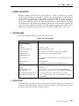
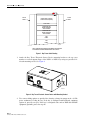
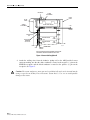
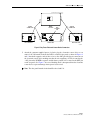
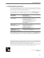
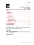
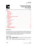
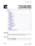
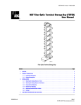
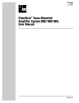
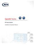
ADCP-80-412 x Issue 1 x April 2000 DSX Bay Tracer Illuminator User Manual 13914-B Content Page INTRODUCTION .......................................................................... 1 Revision History ..................................................................... 2 Trademark Information ................................................................ 2 Admonishments ..................................................................... 2 Certification ........................................................................ 2 1 PRODUCT DESCRIPTION ............................................................... 2 2 SPECIFICATIONS..................................................................... 3 3 INSTALLATION ...................................................................... 3 4 OPERATIONAL CONSIDERATIONS ......................................................... 7 5 TROUBLESHOOTING .................................................................. 7 6 CUSTOMER INFORMATION AND ASSISTANCE ................................................. 8 INTRODUCTION This guide describes the ADC DSX Bay Tracer Illuminator option used in large DSX-1 or DSX-3 environments to enable technicians to locate far end LED tracer lamps more quickly. The Bay Tracer Illuminator option consists of a stand-alone electronic sensor device that mounts on the top of a DSX-1 or DSX-3 bay, and an inductive pick-up coil that mounts on one or more –48 Vdc power input conductors feeding the bay fuse panel. Power to operate the Bay Tracer Illuminator option is obtained from a branch of the same –48 Vdc central office source that powers the components in the DSX-1 or DSX-3 bay. 1074399 Rev A Page 1 2000, ADC Telecommunications, Inc. ADCP-80-412 x Issue 1 x April 2000 An LED mounted on the Bay Tracer Electronic Sensor Device provides a large, bright, easily observable, visual indication whenever an individual jack LED is activated on a DSX bay. This allows a technician to identify the far end bay so that a scan can be performed to identify the specific jack LED that has been activated. The indicator flashes for a nominal period of 70–90 seconds following jack activation to allow sufficient time to scan a 6 u 25 bay environment. After the 70–90 second flashing cycle, the LED on the Bay Tracer Electronic Sensor Device is extinguished and reset in preparation for the next tracer event. The individual DSX jack LED lit by the activation flashes for 30 seconds and stays lit in a steady on state until a switch deactivation occurs. Individual jack LEDs are not affected by Bay Tracer Illuminator operation. Revision History ISSUE DATE Issue 1 04/2000 REASON FOR CHANGE Original Trademark Information ADC and ADC Telecommunications are registered trademarks of ADC Telecommunications, Inc. Admonishments Important safety admonishments are used throughout this manual to warn of possible hazards to persons or equipment. An admonishment identifies a possible hazard and then explains what may happen if the hazard is not avoided. The admonishments — in the form of Dangers, Warnings, and Cautions — must be followed at all times. These warnings are flagged by use of the triangular alert icon (seen below), and are listed in descending order of severity of injury or damage and likelihood of occurrence. Danger: Danger is used to indicate the presence of a hazard that will cause severe personal injury, death, or substantial property damage if the hazard is not avoided. Warning: Warning is used to indicate the presence of a hazard that can cause severe personal injury, death, or substantial property damage if the hazard is not avoided. Caution: Caution is used to indicate the presence of a hazard that will or can cause minor personal injury or property damage if the hazard is not avoided. Certification The product described in this manual has been tested and found to comply with the requirements of UL 1863 and CSA C22.2 No. 225. Page 2 © 2000, ADC Telecommunications, Inc. ADCP-80-412 x Issue 1 x April 2000 1 PRODUCT DESCRIPTION Electronic circuitry in the Bay Tracer sensor checks for a change in current on one or more –48 Vdc power conductors on the DSX-1 or DSX-3 fuse panel caused by an individual jack insertion on the far end bay and uses this change to activate an LED. The change in current is detected by a clamp-on inductive pick-up coil encircling the –48 Vdc power conductor(s) attached to the DSX fuse panel of the device being monitored. A two-conductor 8-foot (20.32 cm) trailing sensor cable attached to the inductive pick-up coil is used to transmit a signal to the sensor. A customer supplied two-conductor (–48 Vdc and battery return) power cable is used to transmit power from the fuse panel on the back of the DSX-1 or DSX-3 bay to the sensor. 2 SPECIFICATIONS Bay Tracer Illuminator specifications are provided in Table 1. Table 1. Bay Tracer Illuminator PARAMETER SPECIFICATION Electrical Specification Power Voltage –36 Vdc to –75 Vdc Current Consumption 40mA (maximum) @ –48Vdc Sensor Interface Two conductor cable with screw connections, 22 AWG Light Indicator Off: normal, On: bay current change detected LED Flashing Rate 4 Hz Power Interface Two conductor screw connections for –48 Vdc, and battery return, 18-20 AWG Heat Dissipation 0.96 W (nominal) Fusing 0.5A GMT type (customer provided at DSX fuse panel) Mechanical Specification Weight 1.2 lb (5.44 g) Operating Environment Non-Operating 23° F to 131° F (–5° to 55°C), up to 80% Relative Humidity –40° F to 185° F (–40° C to 85° C), up to 95% Relative Humidity Sensor Dimensions (H u W u D) 1.75 in. (4.45 cm) u 4.25 in. (10.8 cm) u 3 in. (7.62 cm) Coil Dimensions (H u W u D) 3 2.1 in. u (5.3 cm) u 2.0 in. (5.1 cm) u 0.610 in. (1.55 cm) 3/4-in. opening INSTALLATION The ADC Bay Tracer Electronic Sensor is designed to be installed on the top cross-member or left/right vertical support flanges of the bay. The sensor and power cabling for the device must be routed over the top of the bay as shown in Figure 1. Page 3 © 2000, ADC Telecommunications, Inc. ADCP-80-412 x Issue 1 x April 2000 FILLER PANEL FILLER PANEL BLANK PANEL (FRONT) CABLE TROUGH (REAR) FUSE PANEL RESERVED FOR MISCELLANEOUS APPLICATIONS RESERVED FOR MISCELLANEOUS APPLICATIONS DSX PANEL DSX PANEL 14093-A NOTE: SENSOR AND POWER ATTACHMENT POSITION AND APPEARANCE SHOWN EXAGGERATED FOR CLARITY. Figure 1. Bay Tracer Cable Routing 1. Attach the Bay Tracer Electronic Sensor Device mounting bracket to the top cross member or vertical support flange of the DSX-1 or DSX-3 bay using two provided 12– 24 rack mounting-screws. See Figure 2. 14001-B Figure 2. Bay Tracer Electronic Sensor Device with Mounting Bracket 2. Two sensor cabling options are provided for detecting a change in current on the –48 Vdc power conductor(s) feeding the bay. If the bay is configured with DSX-only equipment (option A), proceed to step 2a. If the bay is configured with a mix of DSX and non-DSX equipment (option B), proceed to step 2b. Page 4 © 2000, ADC Telecommunications, Inc. ADCP-80-412 x Issue 1 x April 2000 a. Unsnap the top bar of the inductive pick-up coil. Insert the main DSX-1 or DSX-3 –48 Vdc power conductor into the inductive pick-up coil as shown in Figure 3, making sure that the label side of the coil faces toward the power source. Snap the top bar back into place after inserting the power feed wire. Anchor the power conductor to the inductive pick-up coil with a tie wrap or lacing cord in accordance with local practice. b. Unsnap the top bar of the inductive pick-up coil. Insert the –48 Vdc conductors for the DSX-only equipment into the inductive pick-up coil as shown in Figure 4, making sure that the label side of the coil faces toward the power source. Snap the top bar back into place after inserting the power feed wire(s). Anchor the power conductor(s) to the inductive pick-up coil with a tie wrap or lacing cord in accordance with local practice. Note: The battery return main conductor, or battery return distribution conductors are not inserted into the coil and should be routed directly to the DSX-1 or DSX-3 fuse panel. SENSOR ATTACHMENT BAYTRACER POWER ATTACHMENT FILLER PANEL FILLER PANEL INDUCTION COIL UPPER CABLE TROUGH —48V FUSE PANEL BATTERY RETURN BATTERY RETURN —48V DSX PANEL BATTERY RETURN —48V DSX PANEL REAR VIEW —48V 14088-A BATTERY RETURN NOTE: SENSOR AND POWER ATTACHMENT POSITION AND APPEARANCE SHOWN EXAGGERATED FOR CLARITY. Figure 3. Sensor Cabling Option A Page 5 © 2000, ADC Telecommunications, Inc. ADCP-80-412 x Issue 1 x April 2000 BAYTRACER POWER ATTACHMENT FILLER PANEL FILLER PANEL UPPER CABLE TROUGH SENSOR ATTACHMENT —48V FUSE PANEL BATTERY RETURN INDUCTION COIL KEEP NON-DSX EQUIPMENT OUT OF COIL BATTERY RETURN —48V DSX PANEL BATTERY RETURN —48V DSX PANEL REAR VIEW —48V 14059-A BATTERY RETURN NOTE: SENSOR AND POWER ATTACHMENT POSITION AND APPEARANCE SHOWN EXAGGERATED FOR CLARITY. Figure 4. Sensor Cabling Option B 4. Attach the trailing wires from the inductive pickup coil to the ADC-provided sensor connector making sure that the white conductor is routed to the negative (–) pin on the SENSOR receptacle and the black conductor is routed to the positive (+) pin on the receptacle. See Figure 5. Caution: The sensor and power connectors are keyed identically and can be inserted into the wrong receptacles on the Bay Tracer Electronic Sensor Device. Use care to avoid possible damage to the sensor. Page 6 © 2000, ADC Telecommunications, Inc. ADCP-80-412 x Issue 1 x April 2000 POWER CONNECTOR LEFT SIDE VIEW TOP VIEW SENSOR CONNECTOR RED FLASHING LED FRONT VIEW RIGHT SIDE VIEW 13928-B Figure 5. Bay Tracer Electronic Sensor Device Connectors 5. Attach the customer-supplied power feed wires for the electronic sensor device to an unused –48 Vdc branch circuit on the DSX-1 or DSX-3 fuse panel as shown in Figures 3 and 4. Attach the opposite ends of these wires to the ADC-provided power connector on the electronic sensor device making sure that the wire supplying –48 Vdc is routed to the –48V pin on the POWER receptacle and the battery return wire is routed to the RET pin on the receptacle. See Figure 5. A reverse blocking diode is incorporated into the electronic sensor device to prevent damage from a power lead reversal. Note: The fuse panel branch circuit should be fused at 0.5 A. Page 7 © 2000, ADC Telecommunications, Inc. ADCP-80-412 x Issue 1 x April 2000 4 OPERATIONAL CONSIDERATIONS The electronic sensor device LED may be falsely activated by external EMI emitted by power drills, wire wrap guns, or other AC powered devices located within 12 inches of the inductive pick-up coil. If such a condition occurs, the electronic sensor device automatically resets after the change in current state and returns to a constant dc state. 5 TROUBLESHOOTING The LED on the bay tracer electronic sensor device is designed to light whenever an individual jack LED is activated on a DSX bay configured with the device. Table 2 provides a description of common error conditions that may occur due to improper installation. Table 2. Bay Tracer Troubleshooting CONDITION DESCRIPTION Battery return conductor inserted into coil LED activates when jack is removed Labeled side of coil is facing away from the power source LED activates when jack is removed Both –48 Vdc and battery return conductors are inserted into the coil Bay Tracer Illuminator does not function –48 Vdc and battery return conductors are mis-wired on POWER connector Bay Tracer Illuminator does not function Page 8 © 2000, ADC Telecommunications, Inc. ADCP-80-412 x Issue 1 x April 2000 6 CUSTOMER INFORMATION AND ASSISTANCE For customers wanting information on ADC products or help in using them, ADC offers the services listed below. To obtain any of these services by telephone, first dial the central ADC telephone number, then dial the extension provided below. The central number for calls originating in the U.S.A. or Canada is 1-800-366-3891. For calls originating outside the U.S.A. or Canada, dial country code “1” then dial 952-946-3000. Sales Assistance Extension 3000 • Quotation Proposals • Ordering and Delivery • General Product Information Systems Integration Extension 3000 • • • • • • • Complete Solutions (from Concept to Installation) Network Design and Integration Testing System Turn-Up and Testing Network Monitoring (Upstream or Downstream) Power Monitoring and Remote Surveillance Service/Maintenance Agreements Systems Operation BCG Technical Assistance Center Extension 3475 E-Mail: [email protected] • • • • • • Technical Information System/Network Configuration Product Specification and Application Training (Product-Specific) Installation and Operation Assistance Troubleshooting and Repair Product Return Department Extension 3748 E-Mail: repair&[email protected] • ADC Return Authorization number and instructions must be obtained before returning products. Product information may also be obtained using the ADC web site at www.adc.com or by writing ADC Telecommunications, Inc., P.O. Box 1101, Minneapolis, MN 55440-1101, U.S.A. Contents herein are current as of the date of publication. ADC reserves the right to change the contents without prior notice. In no event shall ADC be liable for any damages resulting from loss of data, loss of use, or loss of profits and ADC further disclaims any and all liability for indirect, incidental, special, consequential or other similar damages. This disclaimer of liability applies to all products, publications and services during and after the warranty period. This publication may be verified at any time by contacting ADC’s Technical Assistance Center at 1-800-366-3891, extension 3475 (in U.S.A. or Canada) or 952-946-3000 (outside U.S.A. and Canada), or by writing to ADC Telecommunications, Inc., Attn: Technical Assistance Center, Mail Station #71, P.O. Box 1101, Minneapolis, MN 55440-1101, U.S.A. © 2000, ADC Telecommunications, Inc. All Rights Reserved Printed in U.S.A. Page 9