1
STEREO
PREAMP-AMPLIFIER
MA230
GENERAL DESCRIPTION
1
TECHNICAL DESCRIPTION
Mechanical Specifications
Electrical Specifications
1
3
3
FRONT PANEL INFORMATION
5
INSTALLATION
CONNECTIONS
TABLE OF CONTENTS
AC Connections
Ground Connection
Tape Output Connections
Loudspeaker Connections
AC Power
Input Connections
9
11
11
11
12
12
12
12
OPERATING INSTRUCTIONS
14
GUARANTEE
20
3-YEAR FACTORY SERVICE CONTRACT
20
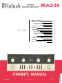
MA230
MA230 PREAMP-AMPLIFIER
GENERAL DESCRIPTION
The new Mclntosh MA230 presents two
outstanding "FIRSTS" for your home stereo
listening enjoyment.
. . . The MA230 is the FIRST stereo preamp-amplifier on one chassis that meets the
traditional rigorous Mclntosh engineering
performance standards.
. . . The MA230 is the FIRST stereo instrument to combine a solid state preamplifier
with a tube and transformer power amplifier
on the same chassis.
The Mclntosh MA230 has eliminated all
previous limitations of single chassis preamppower amplifiers. The compact design of the
MA230 preamplifier allows adequate space
on the same chassis for a cool running 30
watt per channel tube power amplifier. You
can now enjoy Mclntosh performance and
reliability with the convenience of a complete
single chassis stereo instrument.
The dramatic difference in the quality of
music reproduction through Mclntosh instruments is due directly to low distortion per-
formance. Mclntosh Laboratory is the only
manufacturer in the entire industry to guarantee and deliver the lowest distortion at all
audio frequencies.
Long life, flexibility, and highest quality
construction are characteristic designs in
every Mclntosh instrument. Wide electrical
and thermal margins of safety for all components, transistors and tubes add to the
long life built into every Mclntosh product.
Advanced engineering and cool operating design insure reliability and low maintenance
costs. A Mclntosh instrument is without
doubt the most economical and worthwhile
long term investment in the high fidelity
industry.
Once you have enjoyed the outstanding
performance of the MA230, you will understand why Mclntosh products have earned
their reputation as "THE BEST." Your Mclntosh MA230 stereo preamp-amplifier will
give you years of the finest possible performance and will become a highly valued
part of your home music system.
TECHNICAL DESCRIPTION
The new Mclntosh MA230 combines, for
the first time, a Mclntosh engineered stereo
solid state preamplifier and tube power amplifier on the same chassis. Long months of
diligent research by the Mclntosh engineering staff have produced a compact solid state
preamplifier which meets all the traditional
Mclntosh performance standards. The MA230 solid state preamplifier eliminates the
drawbacks and limitations of all previous
solid state circuits. The compact design of
this preamplifier has allowed sufficient space
to properly position a 30 watt per channel
stereo tube power amplifier on the same
chassis.
The MA230 continues the Mclntosh reputation for cool and efficient operation. Careful
chassis planning has permitted the output
tubes to be spaced well apart. This wide
spacing allows more air circulation around
the tubes. Better air circulation means cooler
operation. Cooler operation means longer
trouble free life. The large Mclntosh output
and power transformers are positioned across
the center of the chassis for mechanical
stability and strength.
The MA230 preamplifier section is designed around the latest type Silicon-Planar
transistors. Silicon-Planar transistors were
selected because of their high thermal stability, low leakage, low noise, and superior
high frequency response. A total of 12 transistors are used. Three transistors are used
in each channel of the phono preamplifier
section. Three transistors are also used in
1
each channel of the tone control section. The
entire preamplifier has low noise, low distortion, and is not affected by normal room
temperature variations.
Typical Mclntosh care in design protects
against input signal overload. Both the high
level inputs (Tuner, Tape and Aux) and the
low level phono and tape head inputs can
accept much higher than average input signals without overload.
For example, at 2000 cycles the phono
inputs can-accept 150 millivolts of signal before overload. No magnetic phono cartridge
now available is capable of even one half this
output voltage.
PREAMPLIFIER
Each channel of the Phono preamplifier
section uses 3 transistors. The first input
stage is a high gain amplifier. The output of
this transistor feeds a pair of transistors connected in a Darlington configuration. A negative feedback loop connects from the output
of the Darlington pair back to the emitter of
the first stage transistor. This feedback loop
reduces noise and distortion and also provides accurate frequency compensation for
phono records and tape head playback. Negative feedback remains in effect even at 20
cycles where gain is highest, to insure low
distortion over the entire frequency range.
The phono input impedance is 47,000
ohms to match most magnetic phono cartridges. Other resistors may be added to
match the occasional cartridge which requires a different input impedance.
The Tape Head input impedance is slightly
over 1 megohm for uniform high frequency
response with typical tape playback heads.
The Tape Outputs come directly from the
Selector Switch and provide signal level sufficient for feeding a tape recorder. For example, 10 millivolts of signal at the phono
input results in 1.6 volts at the Tape Output.
The high level inputs feed through the
Balance and Volume controls into a transistor
connected as an Emitter-Follower. This transistor is the first stage of the Tone Control
section. The impedance of the high level
inputs is 250,000 ohms. Any conventional
2
tuner or tape recorder may be connected to
the MA230 without loss of low frequencies.
The emitter-follower provides the required
high input impedance and low output impedance for feeding the tone control negative
feedback circuits. The last two stages of the
tone control section are two transistors in a
Darlington configuration similar to the phono
preamplifier. The high gain of these stages
is used to advantage for the tone control
negative feedback circuits. This type of circuit assures low distortion and the correct
shape for the tone control response curves.
Negative feedback is maintained at all frequencies, even with the tone controls turned
to full boost. Distortion is, therefore, kept
very low, even at the frequencies where
maximum boost occurs. The total distortion
of the entire MA230 preamplifier circuit is
actually only a few hundredths of 1 percent.
POWER AMPLIFIER
The output of the solid state preamplifier
feeds into one half of a 12AX7 dual triode
tube. The two triode sections of the 12AX7
are the first stage voltage amplifiers in each
channel of the power amplifier. The output of
each 12AX7 is direct-coupled to a 12AU7
tube used as a grounded-grid inverter-driver.
The balanced output voltages of the groundedgrid inverter are precisely maintained in
amplitude over the entire audio frequency
range. The inverter output balance is controlled by precise plate load resistors. An
adjusting control is also included in the inverter plate circuit to insure exact signal balance and minimum low frequency distortion.
This control is factory set using a distortion
analyzer. Normally, the mid point setting of
this control is adequate to keep overall distortion less than ½ of 1% at full output.
The outputs of the 12AU7 tubes are coupled through mylar-insulated capacitors to
the output tube grids. These capacitors are
the only coupling capacitors used in the
power amplifier circuit, which keeps phase
shift very low at low frequencies.
The 7591 output tube plates are coupled
to the speaker through a special Mclntosh
engineered output transformer. A separate
tertiary winding on the transformer also
couples the output tube cathodes into the
transformer. Six db of negative feedback is
produced in the output stage with this circuit.
Twenty db of negative feedback around
the entire power amplifier circuit is achieved
by coupling a special secondary winding on
the output transformer back to the first stage
12AX7 cathode.
The fixed bias on the 7591 output tubes
is adjustable over a small range with individual controls. These adjustments are factory set to 0.7 volts DC at the test points.
Convenient test point jacks are provided next
to each output tube. The setting of these controls is not critical and need not be touched
in normal use. To assure best possible performance of the MA230 over long periods of
operation, or whenever output tubes are
changed, the bias can be checked and reset
if necessary.
A pair of stereo headphone jacks is provided on the front panel. The jacks are connected to the amplifier outputs through 100
ohm resistors for low impedance head phones.
The speaker switch turns off the speakers
for headphone listening.
POWER SUPPLY
A silicon rectifier voltage doubler power
supply assures stable voltages and cool operation. A zener diode holds the transistor preamplifier operating voltages at exact values
and eliminates all traces of hum.
A thermistor is used in the primary AC
circuit of the power transformer to protect
against line voltage surges and extend tube
and transistor life. The thermistor places
slightly more than 25 ohms in the AC circuit
when cold. As the amplifier warms up the
thermistor also warms and its resistance
then drops to less than 0.7 ohm. The amplifier then operates at normal line voltages but
is protected during the initial warmup period.
Again, Mclntosh care in engineering protects
your investment in listening pleasure.
The combination of these features results
in performance available only from a Mclntosh amplifier. The MA230 delivers 30
watts RMS continuous power from both
channels at the same time, 20 cycles through
20,000 cycles with harmonic distortion less
than ½ of 1%. This superior level of performance is unequaled by any other preampamplifier. A listening test quickly proves the
superiority of the Mclntosh MA230.
MECHANICAL SPECIFICATIONS
Size
Front panel, 16 inches wide by 57/16 inches
high; chassis, 15 inches wide by 4½ inches
high by 14½ inches deep, including connectors. Clearance in front of mounting panel
including knobs, 1½ inches.
Weight
43 pounds net, 57 pounds in shipping carton.
Finish
Anodized gold and black (Front Panel).
ELECTRICAL SPECIFICATIONS
Power Output
30 watts continuous per channel with both
channels operating simultaneously. 60 watts
continuous, monophonic.
Harmonic Distortion
Less than 0.5% at 30 watts output, 20 cycles
through 20,000 cycles. Distortion decreases
as power output is reduced.
Intermodulation Distortion
Less than 0.5% for any combination of frequencies from 20 cycles through 20,000
cycles if instantaneous peak power is 60
watts per channel or less.
Phase Shift, Power AmplifierLess than ± 5° 20 to 20,000 cycles.
3
Frequency Range
At 30 watts output both channels.
+ 0, -0.5db 20 cycles through 20,000
cycles.
+0, - 3 d b 15 cycles through 70,000
cycles.
Output Impedance
4 ohms, 8 ohms, 16 ohms.
Internal Impedance/Damping
Less than 10% of rated load impedance;
damping factory of 10.
Input Sensitivity and Impedance
Auxiliary, Tape, Tuner, and Tape Monitor:
.25 volts, 250K ohms.
Phono 1 and Phono 2: 1.5 millivolts, 47,000
ohms.
Tape Head: 1.5 millivolts, 1 Megohm.
Total Noise (including Power Amplifier)
High level inputs: 75db below rated output.
Low level inputs: 60db below rated output;
less than 4.0 microvolts at input terminals.
Tape Output
.25 volts into 25,000 ohms with rated input;
1.6 volts with 10 millivolts at Phono input.
Left Plus Right Output
10 volts from generator impedance of 5,000
ohms.
Phase Switch
Normal (0°) or reverse (180°).
Speaker Switch
Speakers ON, or OFF for headphone listening.
HF Filter
Flat, or 5,000 cycle cutoff, 12db per octave.
LF Filter
Flat, or 50 cycle cutoff, 12db per octave.
Loudness Switch
Normal or compensated bass and treble.
Headphone Jacks
Two, for two pairs of headphones.
Input Selector
6 positions: AUX, TAPE, TUNER, PHONO 1,
PHONO 2, TAPE HD.
Mode Selector
7 positions: L to L and R, R to L and R,
STEREO REVERSE, STEREO, MONO (L+R),
L+R to L, L+R to R.
Transistor Complement (Preamplifier)
8-2N2926 Silicon Planar
4-11BQ101 Silicon Planar
Bass Controls
±18db at 20 cycles, with friction clutch for
independent adjustment of each channel.
Tube Complement (Power Amplifier)
4 - 7 5 9 1 Power Output
2-12AU7 Driver/Phase Inverter
1-12AX7 1st Audio Voltage Amplifier
Treble Controls
± 18db at 20,000 cycles, with friction clutch
for independent adjustment of each channel.
Power Requirements
120-125 volts AC, 60 cycles. 150 watts at
zero signal output; 210 watts at rated output.
Comp (Compensator) Switch
RIAA or LP phono equalization.
4
.
Tape Switch
Normal or Tape Monitor.
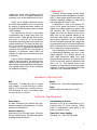
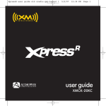
FRONT PANEL INFORMATION
Figure 1. MA230 Front Panel.
INPUT SELECTOR
6. TAPE HD: Use the TAPE HD (Tape
Head) position for a tape deck that does not
have its own playback preamplifier. The Tape
Head leads are connected to the back panel
TAPE HD input jacks.
MODE SELECTOR
Figure 2. INPUT SELECTOR Switch.
Select any of six program sources with the
MA230 INPUT SELECTOR switch.
1. AUX: Use the AUX position for any
auxiliary program source requiring flat amplification, such as a tuner or television sound,
connected to the back panel AUX input jacks.
2. TAPE: Use the TAPE position for a selfcontained tape recorder (tape recorder having its own playback preamplifier), connected
to the back panel TAPE input jacks.
3. TUNER: Use the TUNER position for
any AM, FM, or FM stereo tuner connected to
the back panel TUNER input jacks.
4. PHONO 1: Use the PHONO 1 position
for any magnetic phono cartridge connected
to the back panel PHONO 1 input jacks.
5. PHONO 2: Same as PHONO 1. (For example, PHONO 1 can be connected to a
record changer while PHONO 2 is connected
to a manual turntable.)
Figure 3. MODE SELECTOR Switch.
Use the MODE SELECTOR to:
Listen to normal stereo (see 4 following
and page 15);
Reverse the left and right arrangement of
musical instruments (see 3 following and
page 15).
Balance the amplifiers and loudspeakers
in a stereo system (see 6 and 7 following and
page 15).
Listen to monophonic sound (see 1 and 2
following and page 15).
Listen through both loudspeakers to
either channel of a stereo program source
(see 1 and 2 following and page 15).
5
Turn the MODE SELECTOR to:
1. L TO L & R: connects the "left" input to
both loudspeakers.
2. R TO L & R: connects the "right" input
to both loudspeakers.
3. STEREO REV: connects the "left" input
to the "right" loudspeaker and the "right"
input to the "left" loudspeaker.
4. STEREO: connects the "left" input to
the "left" loudspeaker and the "right" input
to the "right" loudspeaker.
5. MONO (L+R): adds the "left" input
and the "right" input and then connects the
L + R program to both amplifiers and loudspeakers.
6. L + R TO L: connects both left and right
inputs to the "left" loudspeaker only.
7. L+ R TO R: connects both left and right
inputs to the "right" loudspeaker only.
Use the MA230 BALANCE control to balance unequal volume in the left and right
channels of a program source. The volume
of each speaker system relative to the other
can be varied, at the same time the combined
room volume level is not changed.
LEFT . . . turning the control to the left
accents the left channel by reducing the right
channel output.
RIGHT . . . turning the control to the right
accents the right channel by reducing the
left channel output.
BASS
VOLUME
Figure 6. BASS Control.
Figure 4. VOLUME Control.
Use the MA230 VOLUME control to regulate the volume level of both channels. Turning the VOLUME control clockwise increases
volume level.
BALANCE
The BASS control is a dual-concentric
control. The two are friction coupled. The
center knob controls the left channel. The
outer ring controls the right channel. With the
BASS control it is possible to vary the bass
loudness relationship existing between the
left and right speakers. Both controls can be,
turned together as a single adjustment or one
may be held as the other is turned. Clockwise
rotation increases bass loudness; counterclockwise rotation decreases bass loudness.
TREBLE
Figure 5. BALANCE Control.
6
The TREBLE control is dual-concentric
control. The two are friction-coupled. The
center knob controls the left channel. The
outer ring controls the right channel. With
this control it is possible to vary the treble
relationship existing between left and right
speakers. Both controls can be turned together as a single adjustment or one may be
held as the other is turned. Clockwise rotation increases treble loudness; counterclockwise rotation decreases treble loudness.
The MA230 TAPE switch makes it possible
to instantaneously compare recorded material with the source signal. Use the MA230
TAPE switch to know instantaneously, as you
are recording, that the music on the tape is
acceptable. Tape monitor jacks on the back
panel accept a signal from a tape recorder
with a monitor head and preamplifier.
NORMAL . . . the original program source
is fed through the power amplifiers and the
loudspeakers.
MONITOR . . . the recorded sound on the
tape is fed through the power amplifiers and
speakers.
Figure 7. TREBLE Control.
PHASE
COMP (Compensation)
Figure 10. PHASE Switch.
Figure 8. COMP (Compensation) Switch.
Use the COMP switch to correct for phono
equalization introduced by the recording
process. The recording industry has agreed
to record all current LP and stereo recordings
with RIAA equalization. On earlier stereo and
on mono recordings use the position that
sounds best to you.
The PHASE switch corrects for loudspeaker or program phasing. When this
switch is in the 180° position the phase in the
left channel is reversed.
SPEAKER
TAPE
Figure 11. SPEAKER Switch.
Figure 9. TAPE Switch.
The loudspeakers are turned off when the
SPEAKER switch is in the OFF position, to
allow listening through headphones. The
headphone jacks are on at all times.
7
LF (Low Frequency Filter)
LOUDNESS
Use the LF filter to reduce low frequency
noises created by a turntable, record changer,
or vibration acoustically coupled to the phono
player from the speakers.
FLAT.. .filter disconnected; flat response.
FILTER . . . low frequencies reduced
sharply below 50 cycles.
When you turn down the volume, music
seems to lose much of its bass and some of
its treble. This effect is due to the sensitivity
characteristics of human hearing. The response of the human ear to bass and treble
pitch decreases more rapidly than its response to the mid-tonal range. The LOUDNESS switch automatically provides the correct amount of bass and treble boost required to compensate for this change in
response of the human ear at low loudness
levels. Use the LOUDNESS switch in the
COMPENSATED position to listen at low
volume and still hear full frequency range.
HF (High Frequency Filter)
HEADPHONE
SPEAKER
POWER
ON
ON
HEAD PHONE
HEAD PHONE
OFF
Use the HF filter to minimize surface noise
when reproducing old or badly worn recordings.
FLAT... filter disconnected; flat response.
FILTER . . . high frequencies reduced
sharply above 5000 cycles.
8
OFF
Two pairs of low impedance stereo headphones can be connected to the MA230.
Both front panel headphone jacks are connected to the MA230 output through 100
ohm resistors. These resistors provide the
correct output volume level for headphone
operation.
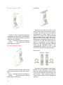
INSTALLATION
The MA230 can be installed in furniture
cabinets, custom built installations or professional relay racks. If the unit is to be used
on a shelf or table top, it can be housed in an
attractive Mclntosh cabinet.
Allow sufficient cabinet space for air circulation. Minimum internal cabinet dimensions
should be at least 16 inches wide, 14 inches
deep, and 6 inches high. The back of the
cabinet should be left as open as possible for
ventilation. Proper ventilation will insure your
amplifier a long and trouble-free life,
The MA230 installs conveniently from the
front of the cabinet into the panel cutout.
Two amplifier mounting brackets are provided for each side of the cabinet panel opening so the MA230 can slide easily into position. The mounting brackets are attached to
the cabinet panel by two mounting strips.
The mounting strips are attached to the back
of the cabinet panel on each side of the panel
cutout. With the screws supplied, front cabinet mounting panels up to one inch thickness
may be used. Two knurled screws placed into
the MA230 back panel, through the mounting
brackets, hold the unit firmly in place. Due to
the weight of the MA230, it is recommended
that the mounting brackets rest on a wooden
shelf in the cabinet for added support.
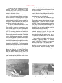
The design of the mounting template
allows the cutout to be located either from
the front or the back of the cabinet panel.
Since the MA230 should rest on a shelf, locate the cutout from the back of the panel.
1A. Position the MA230 mounting template on the cabinet panel area to be cutout
for the installation.
Figure 17. Positioning the Mounting Template
over proposed area to be cutout.
1B. On the back of the cabinet panel,
scribe a vertical line through the exact center
of the cutout area.
Place the template against the back of the
panel. Match the template centerline with the
scribed cutout centerline. The bottom of the
template must rest on the shelf.
1C. On each side of the centerline of the
template there are two holes marked "C."
The smaller diameter hole is below the larger
diameter hole. These are the "LOCATING
HOLES." These holes are used to locate the
front panel of the MA230 with reference to
the shelf behind the cabinet panel. So that
the MA230 will rest on the cabinet shelf, follow these instructions carefully.
Mark the back of the cabinet panel with a
pointed instrument through the two small
diameter "LOCATING C" holes. Drill these
two holes through the cabinet panel with a
3
/16" diameter drill. Be certain the drill is perpendicular to the panel.
Now position the template on the front of
the panel. Align the larger 3/16" diameter
upper "LOCATING C" holes in the template
with the drilled holes in the cabinet panel.
2. Mark the "A" and " B " drill holes and
also the four corner cutouts in the template.
Join the corner markers. The edge of the
template can be used as a straight edge.
Figure 18. Marking the Cutout Indications.
3. First drill the mounting holes.
9
4. Cut out the rectangular opening.
Figure 19. Installation Cutout.
5. Secure the mounting strips to the inside of the panel.
Tighten the flat head screw so that the
screw head pulls in the wood panel level with
the panel surface. Repeat this with the second mounting strip on the other side of the
rectangular cutout.
6. Left and right metal mounting brackets
are packed with the MA230. Fasten these two
mounting brackets to the cabinet panel using
four of the fillister head screws. These screws
should pass through the mounting shelf
flange, through the cabinet panel and then
into the mounting strip attached to the inside
of the panel. Tighten the screws firmly, but
do not over-tighten.
7. Prepare the MA230 for mounting by
removing the four plastic feet fastened under
the chassis.
Figure 20. Securing Mounting Strips
to Installation Cutout.
In the hardware package are 4 flat head
screws and 8 fillister head screws. Two of the
flat head screws of the proper length are
used to attach the mounting strips to the
cabinet panel. Four of the fillister head
screws are used to attach the MA230 mounting brackets to the cabinet panel and the
mounting strips behind the panel. The ¼ inch
screws are used for panel thickness less than
3
/8 inch. The 1¼ inch screws are used with
panels from 3/8 inch to 1 inch in thickness.
Insert the proper length flat head screw
through the center " B " holes of the cabinet
panel ("B" holes marked on mounting template). Position the mounting strip behind
the cabinet panel. The edge of the mounting
strip that has the clips must be facing the
rectangular cutout. Align the three holes in
the mounting strip with the holes in the cabinet panel.
Figure 21. Mounting Brackets installed in cabinet panel.
10
8. The MA230 is installed from the FRONT
of the cabinet. Insert the MA230 power cord
through the rectangular opening of the cabinet panel. Carefully slide the MA230 into the
opening so the plastic rails on the bottom of
the chassis engage the grooves in the metal
mounting brackets. Slide the MA230 in until
its front panel is against the cabinet mounting panel.
9. Secure the MA230 to the mounting
brackets by inserting the two knurled screws
into the back of the MA230 chassis, through
the back flanges of the mounting brackets.
Figure 22. Securing MA230 to Mounting Brackets.
CONNECTING
AC CONNECTIONS
There are three AC outlets on the back
panel of the MA230. The black receptacles
have a maximum power rating of 350 watts
total. The power to the two black receptacles
is controlled by the front panel power switch.
Use these receptacles for accessories such
as a tuner and tape recorder. The red receptacle is not switched. Use the red receptacle for powering a turntable or record
changer. The red receptacle is not switched
to prevent turning off the power to the turntable while its idler drive is still engaged. The
turntable is protected by this arrangement
because it is necessary to turn off the turntable with its own control switch. The turntable drives will then be properly disengaged
to avoid possible damage.
Figure 23. AC CONNECTIONS
L+R OUTPUT
Both left and right channel amplifier outputs are combined into a monophonic signal
at the L+R output jack. Connect this jack to
an external amplifier for monophonic reproduction through another speaker system.
Monophonic signals can then be distributed
to other rooms without affecting the normal
stereo performance of the MA230.
GROUND CONNECTIONS
A single ground post is provided on the
MA230. The chassis ground from turntables,
record changers, tape decks, etc., should be
connected to this post. Do not connect other
ground wires to the same units. Hum is
likely to be heard in the system if more than
one ground circuit is used.
The left and right cables from each pro-
11
gram source should be twisted together and
the ground wire from each source can be
wound or twisted in with these cables. To
avoid hum, make sure the ground wire does
not make any connections to shields of the
left and right channel cables except for the
connection provided with the MA230 ground
post.
TAPE OUTPUT CONNECTIONS
The TAPE OUTPUTS on the back panel
provide the program material with sufficient
level for feeding a tape deck or recorder. The
TAPE OUTPUT signal is not affected by
these front panel controls: VOLUME, BASS,
TREBLE, BALANCE, LOUDNESS, PHASE,
TAPE, MODE SELECTOR, SPEAKER, LF and
HF FILTERS. The INPUT SELECTOR and the
COMP switch (in Phono 1 and Phono 2) affect
the TAPE OUTPUTS. All recording volume
adjustments are made at the tape recorder.
The room listening volume of the MA230 can
then be set at any desired level without
affecting recording volume.
LEFT and RIGHT SPEAKER OUTPUT
Speaker systems of 4, 8, or 16 ohms impedance connect to the SPEAKER terminals
on the back panel of the MA230.
Select the output impedance desired by
placing the wire pigtail with the lug under the
appropriate impedance screw on each channel. Tighten the screws firmly. Connect the
left speaker leads to the two screws under
the lettering marked LEFT SPEAKER. Connect the right speaker leads to the two screws
under the lettering marked RIGHT SPEAKER.
The common or chassis ground tap on each
channel is marked C. Connect each speaker
in an identical manner.
AC POWER
Plug the AC power cord into a 120-125
volt, 50 or 60 cycle power line.
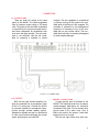
INPUT CONNECTIONS
The MA230 provides seven separate program inputs controlled by the INPUT SELEC-
CONNECTION
TAPE MONITOR
AUX
TAPE
TUNER
CONNECTION
12
TOR switch. The input for tape monitor is
controlled by the TAPE switch.
FUNCTION
INPUT
SENSITIVITY
INPUT
IMPEDANCE
0.25 V
250K
0.25 V
250K
The tape monitor input accepts a signal from a tape
recorder with a monitor head and preamplifier
The auxiliary input accepts any auxiliary service requiring flat frequency response, such as a T.V. set, tuner,
tape recorder with its own playback preamplifier, etc.
The tape input operates with tape machines containing
their own playback preamplifier
The tuner inputs accept AM and FM outputs from a
stereo tuner or a pair of stereo tuners or the multiplex
output of an adapter of multiplex tuner
0.25 V
250K
0.25 V
250K
FUNCTION
INPUT
SENSITIVITY
INPUT
IMPEDANCE
PHONO 1 & 2
These jacks are to be used with magnetic cartridges,..
1.5 MV
47K
TAPE HEAD
These jacks are to be used with a tape deck that does
not contain its own playback preamplifier
1.5 MV
1 megohm
DIRECTIONAL
FM ANTENNA
ROTATOR
GROUND
TO 12OV
AC OUTLET
8 OHM SPEAKERS SHOWN
13
If a phono cartridge requires less than
47,000 ohms load impedance, a resistor can
be added across the terminals of the car-
tridge to achieve the correct termination.
The following chart may be used as a guide:
Desired Impedance
Resistor Across Input
47,000
37,000
27,000
15,000
6,800
No Resistor
180,000 ohms
62,000 ohms
22,000 ohms
8,200 ohms
ohms
ohms
ohms
ohms
ohms
(47K)
(37K)
(27K)
(15K)
(6.8K)
(180K)
(62K)
(22K)
(8.2K)
OPERATING INSTRUCTIONS
BALANCING A STEREO SYSTEM
The performance and enjoyment of a
stereo system is greatly increased when the
system is properly balanced. The balance of
a stereo system is affected by many things
including room acoustics, furniture placement, room shape, small differences in loudspeakers, and unequal program loudness.
The control marked BALANCE on the
MA230 can be used to perfectly balance all
factors for best listening.
1. Play a familiar recording on the record
player.
2. Turn the INPUT SELECTOR to the
PHONO position into which the record player
is connected.
3. Turn the BASS and TREBLE controls
so that the knob indicators are centered between the panel markings L and R.
4. Turn the BALANCE control to the center or 12 o'clock position.
5. Place the LOUDNESS switch in the
NORMAL position.
6. Place the TAPE switch in the NORMAL
position.
7. Place the PHASE switch in the 0°
position.
14
8. Place the LF filter switch in the FLAT
position.
9. Place the HF filter switch in the FLAT
position.
10. Turn the MODE SELECTOR to the
L+R to L position.
11. While the program is playing, alternate the MODE SELECTOR between the L+R
to R and the L+R to L positions. Adjust the
MA230 BALANCE control until the loudspeaker volumes are equal.
The stereo system will now be balanced.
Different program material such as records,
tapes or FM broadcasts may require different
BALANCE control settings. It is not at all unusual for the BALANCE control to remain off
center one way or the other for correct balance. This means the BALANCE control is
performing the function it was designed for.
ADJUSTING PHASE
1. Set the MODE SELECTOR to STEREO.
2. Turn the BASS controls and TREBLE
controls to straight up position with the dial
indicators centered between the panel markings L and R.
3. Stand approximately 10 feet in front of
and midway between the loudspeakers. The
source of sound should appear to be directly
in front of you. Alternate the PHASE switch
between 0° and 180°. If the sound is not directly in front of you in the 0° position, reverse the leads to one loudspeaker. The
PHASE switch is used to correct phase in the
source material whenever necessary.
ADJUSTING FOR SPECIAL EFFECTS
HF FILTER
If you wish to reproduce badly worn
records, you can minimize the surface noise
by switching the HF filter to the FILTER position.
LF FILTER
If you are using a turntable or changer
which has low-frequency rumble noise, you
may reduce it by pushing the LF filter switch
to the FILTER position.
BASS CONTROLS AND TREBLE CONTROLS
The tone balance which you hear when
listening to an orchestra is affected by the
conductor's instructions to his musicians,
the acoustical environment in which you are
listening, and your own subjective hearing
interpretation. Considering these conditions,
it is easy to see why tone balance controls
play a major role in correcting for the following factors:
1. Each person's subjective idea of tone
balance.
2. Loudspeaker frequency response characteristics.
3. Loudspeaker placement in the listening room.
4. The conductor's idea of tone balance
at the time the recording was made.
5. The microphone frequency response
characteristics.
6. The recording process influences.
These factors can be considered as environmental influences. The BASS CONTROLS and TREBLE CONTROLS provide a
degree of compensation for effects of environment. Listen to your system with each
control set with the indicators centered between the panel markings L and R. If you
wish to reduce treble in relation to bass for
example, turn the TREBLE CONTROLS counterclockwise until the tone balance sounds
correct to you. These controls will modify
tone balance without introducing any undesirable effects. Do not be surprised if you
find your preference in tone changing from
time to time.
PHASE
If the stereo sound seems to come from
either side of the room instead of being distributed between the loudspeakers, turn the
PHASE switch to 180°. This listening effect
is due to reproducing sound that is out of
phase from one channel to the other. You
will find some records and tapes may differ
from others in this respect.
LISTENING TO A STEREO TUNER
1. Turn the INPUT SELECTOR to TUNER.
2. Turn the MODE SELECTOR to STEREO.
3. Set the PHASE switch to 0°.
4. Set the HF cutoff filter switch to FLAT.
(See page 15 ADJUSTING FOR SPECIAL
EFFECTS.)
5. Set the LF filter switch to FLAT. (See
page 15 ADJUSTING FOR SPECIAL EFFECTS.)
6. Set the LOUDNESS switch to NORMAL.
(See page 15 ADJUSTING FOR SPECIAL
EFFECTS.)
7. Turn the BASS CONTROLS and TREBLE
CONTROLS so that the indicators are centered between the panel markings L and R.
(See page 15 BASS AND TREBLE CONTROLS.)
8. Set the TAPE switch to NORMAL.
9. Adjust the VOLUME control to the desired volume.
10. Adjust the BALANCE control if necessary.
After a warm up of about 30 seconds, turn
the tuning knob on your tuner to find the
station of your choice.
LISTENING TO A STEREO RECORD
To listen to stereo records, proceed as
follows:
1. Turn the INPUT SELECTOR to PHONO
1 or PHONO 2, whichever is connected to the
cartridge you wish to hear.
2. Set the MODE SELECTOR to STEREO.
3. Set the PHASE switch to 0°.
4. Set the HF cutoff filter switch to FLAT.
15
(See page 15 ADJUSTING FOR SPECIAL
EFFECTS.)
5. Set the LF filter switch to FLAT. (See
page 15 ADJUSTING FOR SPECIAL EFFECTS.)
6. Set the LOUDNESS switch to NORMAL.
(See page 15 ADJUSTING FOR SPECIAL
EFFECTS.)
7. Set the TAPE switch to NORMAL.
8. Set the BASS CONTROLS and TREBLE
CONTROLS so that the indicators are centered between the panel markings L and R.
(See page 15 BASS and TREBLE CONTROLS.)
9. Adjust the VOLUME control to the desired volume.
10. Adjust the BALANCE control if necessary.
LISTENING TO MONOPHONIC RECORDS
To listen to monophonic records, proceed
as follows:
1. Turn the INPUT SELECTOR to PHONO
1 or PHONO 2, whichever is connected to the
cartridge you wish to hear.
2. Turn the MODE SELECTOR to MONO
(L+R).
3. Set the PHASE switch to 0°.
4. Set the HF cutoff filter switch to FLAT.
(See page 15 ADJUSTING FOR SPECIAL
EFFECTS.)
5. Set the LF filter switch to FLAT. (See
page 15 ADJUSTING FOR SPECIAL EFFECTS.)
6. Set the LOUDNESS switch to NORMAL.
(See page 15 ADJUSTING FOR SPECIAL
EFFECTS.)
7. Set the BASS CONTROLS and TREBLE
CONTROLS so that the indicators are centered between the panel markings L and R.
(See page 15 BASS AND TREBLE CONTROLS.)
8. Adjust the VOLUME control to the desired volume.
9. Adjust the BALANCE control if necessary.
LISTENING TO TAPE DECKS
To listen to tape from a tape deck, proceed
as follows:
1. Turn the INPUT SELECTOR to TAPE
HEAD.
16
2. Turn the MODE SELECTOR to MONO
(L+R) or STEREO, depending on the program on the tape.
3. Set the PHASE switch to 0°.
4. Set the HF cutoff filter switch to FLAT.
(See page 15 ADJUSTING FOR SPECIAL
EFFECTS.)
5. Set the LF filter switch to FLAT. (See
page 15 ADJUSTING FOR SPECIAL EFFECTS.)
6. Set the LOUDNESS switch to NORMAL.
(See page 15 ADJUSTING FOR SPECIAL
EFFECTS.)
7. Set the BASS CONTROLS and TREBLE
CONTROLS so that the dial indicators are
centered between the panel markings L and R.
8. Adjust the VOLUME control to the
desired volume.
9. Adjust the BALANCE control if necessary.
LISTENING TO A STEREO TAPE MACHINE
A stereo tape machine with its own playback preamplifiers should be plugged into
the AUX input or the TAPE MONITOR i n p u t not the TAPE HEAD input.
If the TAPE input is used, proceed as
follows:
1. Turn the INPUT SELECTOR to TAPE.
2. Turn the MODE SELECTOR to MONO,
(L+R) or STEREO depending on the program
on the tape.
3. Set the PHASE switch to 0°.
4. Set the HF cutoff filter switch to FLAT.
(See page 15 ADJUSTING FOR SPECIAL
EFFECTS.)
5. Set the LF filter switch to FLAT. (See
page 15 ADJUSTING FOR SPECIAL EFFECTS.)
6. Set the LOUDNESS switch to NORMAL.
(See page 15 ADJUSTING FOR SPECIAL
EFFECTS.)
7. Set the BASS CONTROLS and TREBLE
CONTROLS so that the dial indicators are
centered between the panel markings Land R.
8. Adjust the VOLUME control to the desired volume.
9. Adjust the BALANCE control if necessary.
If the AUX input is used, turn the INPUT
SELECTOR to AUX; then, proceed the same
as for TAPE input.
1. Set the TAPE MONITOR switch to
MONITOR.
2. Turn the MODE SELECTOR switch to
MONO (L+R).
3. Set the HF cutoff filter switch to FLAT.
(See page 15 ADJUSTING FOR SPECIAL
EFFECTS.)
4. Set the LF filter switch to FLAT. (See
page 15 ADJUSTING FOR SPECIAL EFFECTS.)
5. Set the LOUDNESS switch to FLAT.
(See page 15 ADJUSTING FOR SPECIAL
EFFECTS.)
6. Set the BASS CONTROLS and TREBLE
CONTROLS so that the dial indicators are
centered between the panel markings Land R.
7. Adjust the VOLUME control to the desired volume.
8. Adjust the BALANCE control if necessary.
POWER
The POWER ON-OFF switch controls the
AC power to the MA230 and the two black AC
receptacles on the back panel. The red AC
receptacle is not switched, and is on at all
times.
HEADPHONE
Two pairs of low impedance stereo headphones can be connected to the MA230.
Both front panel headphone jacks are connected to the MA230 output through 100
ohm resistors. These resistors provide the
correct output volume level for headphone
operation.
ADJUSTMENTS
Two simple circuit adjustments are included in the MA230. After extensive use or
when tubes have been replaced, these adjustments will insure top performance from
your MA230.
The DC bias of each 7591 output tube can
be individually set. Test Point jacks and bias
adjust controls are conveniently mounted on
the chassis next to each output tube. The
output tubes, Test Point jacks, and bias controls are marked V, TP, and R, respectively.
The bias adjust control can be reached from
the top of the chassis with a small screwdriver. Set the Bias controls for a DC voltage
of 0.7 volts from each Test Point jack to
chassis ground. Use a VTVM or sensitive DC
voltmeter. Check all voltages a second time
and readjust the controls if necessary.
A phase inverter AC signal balance control
is provided on each amplifier channel. These
controls are factory set with a harmonic distortion analyzer for minimum distortion at 20
cycles at 30 watts output. Normally just a
midpoint setting of these controls is adequate to keep overall distortion to less than
0.5% at full output. If the necessary distortion measuring equipment is available, set
each control for minimum harmonic distortion at 20 cycles at 30 watts output. Balance
control R4 adjusts the left channel signal
balance, and R5 the right channel balance.
17
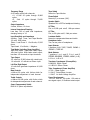
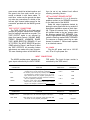
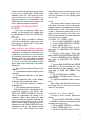
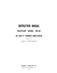
BASS AND TREBLE CONTROL RESPONSE
20
RESPONSE IN DB
10
0
-10
-20
20
100
1KC
10KC
20KC
FREQUENCY
RUMBLE AND HIGH FREQUENCY FILTERS
0
RESPONSE IN OB
-5
-10
-15
-20
-25
-30
20
100
1KC
FREQUENCY
18
10KC
20KC
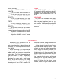
LOUDNESS CONTROL
20
15
RESPONSE IN DB
10
5
0
-5
-10
-15
-20
20
100
1KC
10KC
20KC
10 KC
2 0 KC
FREQUENCY
EQUALIZATION
CURVES
25
20
15
RESPONSE IN DB
10
5
0
-5
-10
-15
-20
-25
20
100
1KC
FREQUENCY
19
Your Mclntosh MA230 tuner will give you many years of pleasant
and satisfactory performance. If you have any questions concerning the operation or maintenance of this tuner please contact:
Customer Service
Mclntosh Laboratory Inc.
2 Chambers Street
Binghamton, New York
Our telephone number is 723-5491.
The direct dial area code is 607.
GUARANTEE
Mclntosh Laboratory Incorporated guarantees this equipment to perform as advertised. We also guarantee the mechanical and
electrical workmanship and components of
this equipment to be free of defects for a
period of 90 days from date of purchase.
This guarantee does not extend to components damaged by improper use nor does it
extend to damage incurred during transportation to and from Mclntosh Laboratory, Inc.
3-YEAR FACTORY SERVICE CONTRACT
An application for a FREE 3-YEAR FACTORY SERVICE CONTRACT is included in the
pocket in the back cover of this manual. The
FREE 3-YEAR FACTORY SERVICE CONTRACT
will be issued by Mclntosh Laboratory upon
receipt of the completely filed out application form. The term of this contract is de-
fined in the 3-year factory service contract.
If the application is not mailed to Mclntosh
Laboratory, only the services offered under
the standard 90-day guarantee will apply on
this equipment. TAKE ADVANTAGE OF 3
YEARS OF FREE FACTORY SERVICE BY
FILLING IN THE APPLICATION NOW.
In Canada: manufactured under license by:
McCurdy Radio Industries, Ltd.
22 Front Street West
Toronto, Canada
Design subject to change without notice.
LABORATORY INC.
2 CHAMBERS STREET, BINGHAMTON, N. Y.
Mods in U.S.A.
Phone-Area Code 607-723-5491
AA133-183