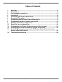
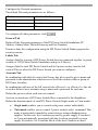
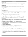
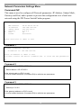
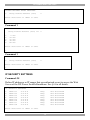
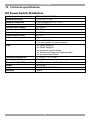
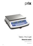
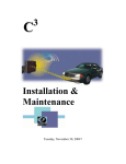
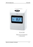
1
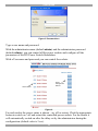
DX Power Switch - 8 Port
User Guide
w w w . m i n i c o m . c o m
International HQ
North American HQ
European HQ
Jerusalem, Israel
Linden, NJ, USA
Dübendorf, Switzerland
Tel: + 972 2 535 9666
[email protected]
Tel: + 1 908 486 2100
[email protected]
Tel: + 41 44 823 8000
[email protected]
Technical support - [email protected]
5UM20132 V1.1 2/07
DX POWER SWITCH 8 PORT
Table of Contents
1.
2.
3.
4.
5.
6.
7.
8.
9.
10.
11.
12.
13.
14.
Welcome........................................................................................................ 2
Introduction................................................................................................... 3
Pre-installation guidelines ............................................................................ 3
Installation..................................................................................................... 4
Connecting DX Power Switch-Slave ............................................................. 4
Assigning ID numbers .................................................................................. 5
Configuring the DX Power Switch-Standalone............................................. 5
Configuration using a Terminal connection ................................................. 8
Security parameters configuration ............................................................. 17
Serial port pin configurations ..................................................................... 18
Commanding the Power Sockets through a Web browser......................... 19
Controlling the Power Sockets via a Serial connection ............................. 21
Controlling the power sockets of a DX Power Switch-Slave or several
Slaves connected together ......................................................................... 22
Technical specifications ............................................................................. 24
1
USER GUIDE
1. Welcome
The DX Power Switch 8 Port system is produced by Minicom Advanced Systems
Limited.
Technical precautions
This equipment generates radio frequency energy and if not installed in accordance
with the manufacturer’s instructions, may cause radio frequency interference.
This equipment complies with Part 15, Subpart J of the FCC rules for a Class A
computing device. This equipment also complies with the Class A limits for radio
noise emission from digital apparatus set out in the Radio Interference Regulation
of the Canadian Department of Communications. These above rules are designed to
provide reasonable protection against such interference when operating the
equipment in a commercial environment. If operation of this equipment in a
residential area causes radio frequency interference, the user, and not Minicom
Advanced Systems Limited, will be responsible.
Changes or modifications made to this equipment not expressly approved by
Minicom Advanced Systems Limited could void the user’s authority to operate the
equipment.
Minicom Advanced Systems Limited assumes no responsibility for any errors that
appear in this document. Information in this document is subject to change without
notice.
No part of this document may be reproduced or transmitted in any form or by any
means, electronic or mechanical, for any purpose, without the express written
permission of Minicom Advanced Systems Limited.
© 2007 Minicom Advanced Systems Limited. All rights reserved.
Trademarks
All trademarks and registered trademarks are the property of their respective
owners.
2
DX POWER SWITCH 8 PORT
2. Introduction
The DX Power Switch 8 Port from Minicom is a power management system
consisting of 2 units.
The DX Power Switch-Standalone can be used as a stand-alone device to control
over IP, 8 IEC power sockets. The number of controlled sockets can be extended to
16, 24, 32 or 40 by cascading 1 to 4 DX Power Switch-Slave.
The DX Power Switch-Slave has a Serial RS232 interface used to control
individually its 8 power sockets either through an DX Power Switch-Standalone or
through any device using a serial RS232 connection (PC, Console server...). By
cascading up to 4 DX Power Switch-Slave, it is possible to control up to 32 sockets
via one serial port.
The Standalone unit has a built-in Web server, an Ethernet and a Serial RS232
connection. It controls the power supply of 8 power sockets either remotely
through a Network (Intranet or Internet) or locally through the serial RS232
connection. It can control up to 40 sockets by connecting up to 4 DX Power
Switch-Slave.
Using two separate power inlets and the optional Twin mode you can control two
power sockets simultaneously, making it the ideal solution to control servers using
redundant power supplies.
DX Power Switch-Slave has a Serial RS232 connection. It controls the power
supply of 8 sockets through its Serial RS232 connection. It can control up to 32
sockets by cascading up to 4 DX Power Switch-Slave. It has two separate power
inlets to increase security and the load available on the power sockets.
3. Pre-installation guidelines
"DX Power Switch" refers to both the above devices.
The DX Power Switch must be installed by qualified personnel using these
installation instructions. The manufacturer disclaims all responsibility in case of
bad utilization or use with equipment that may cause personal injury or material
damage.
This equipment is designed to be installed on a dedicated circuit that must have a
circuit breaker or fuse protection.
The electrical power sockets used must be close to the DX Power Switch and easily
accessible.
Check that the power cables, plugs and sockets are in good condition.
3
USER GUIDE
The DX Power Switch devices can only be connected to three-wire 230 VAC (5060Hz) sockets.
Always plug the DX Power Switch devices into properly grounded power sockets
(two poles plus ground).
Never exceed 10 Amp total load for each group of 4 power sockets of a DX Power
Switch.
If you have to replace an external fuse of a DX Power Switch, only use a
10A/250V T type of fuse.
The DX Power Switch is intended for indoor use only. Do NOT install them in an
area where excessive moisture or heat is present.
Always disconnect the 2 power cables before working on the equipment powered
from the DX Power Switch device.
The power outlets of the DX Power Switch are not circuit breakers! If you want to
work on equipment connected to a DX Power Switch device you must disconnect
this equipment from the DX Power Switch device.
The DX Power Switch contains potentially hazardous voltages. Do NOT attempt to
disassemble them.
The DX Power Switch devices contain no user serviceable parts and repairs are to
be performed by factory trained service personnel only.
4. Installation
Connecting DX Power Switch-Standalone
Connect a 10BaseT cable to the RJ-45 network port and to the DX Power SwitchStandalone.
To configure the DX Power Switch-Standalone or control its power sockets over a
Terminal connection, connect the supplied Serial cable to a Serial port on your PC
and to the Serial port of the DX Power Switch-Standalone.
Plug the 2 power cables into 2 grounded sockets. The A and B LEDs light up
confirming that power is on and the Power LED confirms that the Web server is
powered.
5. Connecting DX Power Switch-Slave
Connect the RJ9 Link-up cable to the RJ9 Out connector of the Standalone and the
RJ9 In connector of the Slave.
To cascade several Slaves, connect the RJ9 Out connector to RJ9 In connector of
the next Slave.
4
DX POWER SWITCH 8 PORT
6. Assigning ID numbers
Assign an ID number to each Slave by positioning the dipswitches marked Slct on
the front panel according to the following table.
Unplug the device before changing its dipswitches.
Do NOT use the same address for two different Slaves.
ID number
Dipswitch 1
Dipswitch 2
1
Off
Off
2
On
Off
3
Off
On
4
On
On
Position Off = switch upwards
Position On = switch downwards
Micro-switch 1 is on the left side, micro-switch 2 on the right.
Plug the 2 power cables into grounded sockets. The A and B LEDs illuminate to
confirm that power is on.
7. Configuring the DX Power Switch-Standalone
To use the switch on your network you must first configure its network parameters.
Ask your Network administrator for the Network parameters to use.
There are 2 configuration methods.
Method 1 - Through a Network using the DX Power Switch Finder Utility (on the
CD).
Method 2 - Through a RS232 Serial connection using a Terminal connection. See
page 8.
Method 1
It is simple and fast if you use a Windows operating system. We recommend using
this program for the first configuration. With it you can configure your DX Power
Switch-Standalone through a local Network even if its network parameters (IP
Address, Subnet mask and Port) are not compatible with those of your PC or your
local network.
The DX Power Switch-Standalone and the PC used to configure it must be
connected on the same segment of the network and not through a WAN or the
Internet.
5
USER GUIDE
Note! The DX Finder Utility uses the UDP protocol.
This program does not work if the administrator has deactivated it in the
configuration of the DX Power Switch.
Start the DX-Finder.exe program on the CD.
The Finder window appears. See Figure 1
Figure 1 DX Finder window
In the Toolbar click
or choose File/Scan. The program displays the name,
type, IP and MAC Address of the connected DX Power Switch.
In the Toolbar click
Figure 2.
or choose File/Configure. The Properties box appears see
Figure 2 Properties box
6
DX POWER SWITCH 8 PORT
Configure the Network parameters.
The default Network parameters are as follows:
IP address
192.168.100.100
Subnet mask
255.255.255.0
Gateway
No address
Port
80
To configure all other parameters, click
.
General Tab
Define all the Network parameters of the DX Power Switch-Standalone (IP
Address, Subnet Mask, Default Gateway and Port Number).
Permit or deny the configuration using the DX Power Switch Finder program for
security reasons.
Labels Tab
Assign a label to a group of DX Power Switch devices connected together (a group
is made of 1 DX Power Switch Standalone and up to 4 Slaves).
Assign a label to each DX Power Switch and its 8 power sockets (use the left
vertical Tabs to select the DX Power Switch you want to configure).
Accounts Tab
In combination with the left vertical tab Group, this tab is used to give a name and
password to the administrator who has access to all the sockets within a group of
DX Power Switches.
In combination with one of the left vertical tabs «Device 1» to «Device 5», this tab
is used to define 8 user accounts using a name and a password for each one.
Define the power sockets each user can control.
Activate or deactivate a DX Power Switch-Slave connected to the Standalone.
Define the function mode of each DX Power Switch (Single mode or Twin mode):
·
Single mode enables you to control each power socket individually.
·
Twin mode enables you to control 2 power sockets with 1 command. This
mode is particularly intended to restart devices using redundant power
supplies. In this case, the 4 sockets powered by power supply A (sockets 1
to 4) are automatically associated with the 4 sockets powered by power
supply B (sockets 5 to 8) and the labels of the first 4 sockets are used.
7
USER GUIDE
Security Tab
Type addresses which are authorized or denied access to the DX Power Switch
over the Network. For details about these features, see section 9 on page 17.
Options Tab
Define the restart delay valid for all power sockets of all DX Power Switch
connected together.
Configure an Email address to which the user can send a message in case of
problems.
Miscellaneous Tab
In combination with one of the left vertical tabs "Device 1" to "Device 5" to know
how many times an DX Power Switch has been powered ON and how many times
its power sockets have been switched from OFF to ON. The user cannot reset these
values.
8. Configuration using a Terminal connection
Through an RS232 Serial connection using a Terminal connection. If you use a PC,
use the Serial cable supplied with the product and a Terminal program such as
Windows HyperTerminal or the MicroTerminal program on the CD (folder
miscellaneous).
The RS232 Serial port of the DX Power Switch-Standalone can be used to control
its power socket and to configure its Web server.
To configure the Web server using a PC and a Terminal connection:
1. Connect the DX Power Switch-Standalone to a Serial port of your PC using the
RS232 Serial cable.
2. Run the Terminal program.
3. Configure the appropriate Serial port with the following settings:
9.600 bauds, 8 bits, no parity, 1 stop bit and no flow control.
If you use the MicroTerminal program from the CD you only have to choose the
used serial port, this program is already configured at 9600, n, 8, 1.
4. On your keyboard, press Enter until the prompt «>» appears. The DX Power
Switch-Standalone is now in Command mode and is waiting for commands to
switch the power sockets. The Serial command mode is explained in section 12
on page 21.
8
DX POWER SWITCH 8 PORT
5. Press the TAB key. The Configuration menu appears and the DX Power
Switch-Standalone is in Configuration mode. Follow the menu below to
configure the DX Power Switch-Standalone Web server.
Figure 3 Configuration menu
All commands start with a slash /.
ex.: type the command /NP to go to the Network Parameters settings menu.
To display the current menu again, press Enter.
To display the previous menu, press Esc.
To leave the Configuration mode, type the restart command /RS. This is important
if you want to control the power socket later through the serial connection.
The configuration of the Serial port is explained in section 10 on page 18.
Configuration Mode Main Menu
The configuration mode Main menu displays all the commands that can be used.
(example: type the command /NP to go to the Network Parameters settings menu.
To display the current menu again, press Enter.
To display the previous menu, press Esc.
9
USER GUIDE
Network Parameters Settings Menu
Command /NP
This menu is used to configure all Network parameters (IP Address, Subnet Mask,
Gateway and Port) and to permit or prevent the configuration over a local area
network using the DX Power Switch Finder program.
NETWORK PARAMETERS SETTINGS
1.
2.
3.
4.
5.
MAC Address
IP Address
Subnet Mask
Gateway
Port
Finder
00.01.9A.F1.00.0F
192.168.100.100
255.255.255.0
0.0.0.0
80
Activated
Enter Selection or <ESC> to exit
>
Command 1
NETWORK PARAMETERS SETTINGS
IP Address is: 192.168.100.100
Enter IP Address or <ESC> to exit
You must restart the device (Command /RS) to valid the new parameters
>
Command 2
NETWORK PARAMETERS SETTINGS
Subnet Mask is: 255.255.255.0
Enter subnet mask or <ESC> to exit
You must restart the device (Command /RS) to valid the new parameters
>
Command 3
NETWORK PARAMETERS SETTINGS
Gateway is: 0.0.0.0
Enter gateway address or <ESC> to exit
You must restart the device (Command /RS) to valid the new parameters
>
10
DX POWER SWITCH 8 PORT
Command 4
NETWORK PARAMETERS SETTINGS
Port is: 80
Enter port or <ESC> to exit
You must restart the device (Command /RS) to valid the new parameters
>
Command 5
NETWORK PARAMETERS SETTINGS
Finder is: Activated
1. Activate
2. Deactivate
Enter Selection or <ESC> to exit
You must restart the device (Command /RS) to valid the new parameters
>
Password Settings Menu
Command /PS
This menu is used to configure the names and the corresponding passwords for the
administrator and all the users.
PASSWORDS SETTINGS
1.
2.
3.
4.
5.
6.
Administrator
Users Device 1
Users Device 2
Users Device 3
Users Device 4
Users Device 5
Enter Selection or <ESC> to exit
>
Command 1
ADMINISTRATOR NAME & PASSWORD SETTINGS
1.
2.
Administrator Name
Administrator Password
admin
admin
Enter Selection or <ESC> to exit
>
11
USER GUIDE
Command 2
DEVICE 1 / USERS SETTINGS
1.
2.
3.
4.
5.
6.
7.
8.
User
User
User
User
User
User
User
User
1
2
3
4
5
6
7
8
Enter Selection or <ESC> to exit
>
Command 1
DEVICE 1 / USER 1 SETTINGS
1.
2.
3.
User 1 Name
User 1 Password
User 1 authorized Sockets
user1-1
user1-1
1,5
Enter Selection or <ESC> to exit
>
Group, Device And Socket Names Settings
Command /NS
This Menu is used to assign a label to:
·
A group of DX Power Switches
·
Each DX Power Switch device
·
Each power socket.
GROUP, DEVICE AND SOCKET NAMES SETTINGS
1.
2.
3.
4.
5.
6.
Group Name
Device 1 &
Device 2 &
Device 3 &
Device 4 &
Device 5 &
Socket
Socket
Socket
Socket
Socket
Name
Name
Name
Name
Name
Group Name
Device 2 name
Device 2 name
Device 3 name
Device 4 name
Device 5 name
Enter Selection or <ESC> to exit
>
12
DX POWER SWITCH 8 PORT
Command 1
GROUP NAME SETTING
Group Name is: Device Name
Enter Name (max. 32 characters) or <ESC> to exit
>
Command 2 to 6
DEVICE 1 / SOCKET NAMES SETTINGS
1.
2.
3.
4.
5.
6.
7.
8.
9.
Device
Socket
Socket
Socket
Socket
Socket
Socket
Socket
Socket
Name
1
2
3
4
5
6
7
8
Device
Socket
Socket
Socket
Socket
Socket
Socket
Socket
Socket
1 name
1-1 name
1-2 name
1-3 name
1-4 name
1-5 name
1-6 name
1-7 name
1-8 name
Enter Selection or <ESC> to exit
Device Parameters Settings
Command /DP
Configure an Email address, to which the user can send a message in case of
problems.
Define the function modus of each DX Power Switch device (Single mode or Twin
mode):
Single mode enables you to control individually each power socket.
Twin mode enables you to control two power sockets with one command. This
mode restarts devices using redundant power supplies.
In this case, the 4 sockets powered by power supply A (sockets 1 to 4) are
automatically associated to the 4 sockets powered by power supply B (sockets 5 to
8) and the labels of the first 4 sockets are used.
Activate or deactivate a DX Power Switch Slave connected to a DX Power Switch
Standalone.
DEVICE PARAMETERS SETTINGS
1.
2.
Mail to
Device #1
Activated
Twin Mode
13
USER GUIDE
3.
4.
5.
6.
Device
Device
Device
Device
#2
#3
#4
#5
Activated
Not Activated
Not Activated
Not Activated
Twin Mode
Single Mode
Single Mode
Single Mode
Enter Selection or <ESC> to exit
>
Command 1
MAIL TO SETTING
Mail to is:
Enter Name (max. 32 characters) or <ESC> to exit
>
DEVICE 1 PARAMETERS SETTINGS
Device #1
1.
2.
Activated
Twin Mode
Single Mode / Twin Mode
Activate / Deactivate
Enter Selection or <ESC> to exit
>
Command 1
DEVICE 1 PARAMETERS SETTINGS
Mode is: Twin Mode
1.
2.
Twin Mode
Single Mode
Enter Selection or <ESC> to exit
>
DEVICE 1 PARAMETERS SETTINGS
Device is: Activated
1.
2.
Activate
Deactivate
Enter Selection or <ESC> to exit
>
Socket Restart Delay Settings
Command /RD
Define the restart delay for all the power sockets.
14
DX POWER SWITCH 8 PORT
SOCKET RESTART DELAY SETTINGS
1.
Delay before Restart (sec)
5
Enter Selection or <ESC> to exit
>
Command 1
SOCKET RESTART DELAY SETTINGS
Delay before Restart (sec) is: 5
1.
2.
3.
4.
5.
5
10
15
30
60
sec
sec
sec
sec
sec
Enter Selection or <ESC> to exit
>
Command 1
SOCKET RESTART DELAY SETTINGS
1.
Delay before Restart (sec)
5
Enter Selection or <ESC> to exit
>
IP SECURITY SETTINGS
Command /IS
Define IP addresses or IP ranges that are authorized or not to access the Web
Server of the DX Power Switch-Standalone. See § 6 for all details.
IP SECURITY SETTINGS
1.
2.
3.
4.
5.
6.
7.
8.
Mask
Mask
Mask
Mask
Mask
Mask
Mask
Mask
#1
#2
#3
#4
#5
#6
#7
#8
0.0.0.0
0.0.0.0
0.0.0.0
0.0.0.0
0.0.0.0
0.0.0.0
0.0.0.0
0.0.0.0
Deny
Deny
Deny
Deny
Deny
Deny
Deny
Deny
Enter Selection or <ESC> to exit
15
Not
Not
Not
Not
Not
Not
Not
Not
Activated
Activated
Activated
Activated
Activated
Activated
Activated
Activated
USER GUIDE
Command 1
IP SECURITY SETTINGS
Mask #1
1.
2.
3.
0.0.0.0
Deny
Not Activated
Edit the Mask
Permit / Deny
Activate / Deactivate
Enter Selection or <ESC> to exit
>
Command 1
IP SECURITY SETTINGS
Mask #1 is: 0.0.0.0
Enter mask or <ESC> to exit
>
Command 2
IP SECURITY SETTINGS
Mask #1 Access is: Deny
1.
2.
Permit
Deny
Enter Selection or <ESC> to exit
>
Command 3
IP SECURITY SETTINGS
Mask #1 Supervision is: Not Activated
1.
2.
Activate
Deactivate
Enter Selection or <ESC> to exit
>
Restarting the device
Command /RS
Restarts the DX Power Switch-Standalone. This function is used to:
·
Show network parameters changes (command /NP).
·
Leave the Serial configuration mode and return to the Command mode.
16
DX POWER SWITCH 8 PORT
RESTART THE DEVICE
The system is reinitializing, please wait ...
>
9. Security parameters configuration
Masks settings:
·
Each mask can be an IP Address or a range of IP Addresses
·
Each mask allows you to permit or deny access to the Web server of the
DX Power Switch-Standalone for specific addresses or ranges of addresses
·
Each mask can be activated or deactivated (without function in this case)
·
Each IP Address consists of a series of 4, 8-bit numbers. The number 255
is used as a wildcard it replaces all others
·
Masks are listed in order of descending priority; so Mask 1 has the highest
priority
·
Masks have a cumulative effect; high priority masks supersede the effect
of lower priority masks
Example 1
Deny access to all IP addresses except 192.168.001.015.
Mask
IP Address
Permit
#1
192.168.001.015
ü
#2
255.255.255.255
Deny
Activated
ü
ü
ü
Deny
Activated
Example 2
Permit access to IP addresses beginning with 192 only.
Mask
IP Address
Permit
#1
192.255.255.255
ü
#2
255.255.255.255
ü
ü
17
ü
USER GUIDE
Example 3
Permit access to IP addresses beginning with 192 only
Deny access to IP address 192.168.001.010
Mask
IP Address
#1
192.168.001.010
#2
192.255.255.255
#3
255.255.255.255
Permit
Deny
Activated
ü
ü
ü
ü
ü
ü
Deny
Activated
ü
ü
Example 4
Permit access to IP addresses beginning with 192.
Deny access to address 192.168.001.010.
Permit access to IP addresses beginning with 217.128.103.
Mask
IP Address
Permit
#1
192.168.001.010
#2
192.255.255.255
ü
#4
217.128.103.255
ü
#3
255.255.255.255
ü
ü
ü
ü
10. Serial port pin configurations
DX Power Switch-Standalone
SUB-D9F connector
Pin configuration
Pin 2 = TxD (transmit data to the PC)
Configuration parameters
Speed
9600 bauds
Pin 3 = RxD (receive commands)
Parity
No
Pin 5 = GnD
Format
8 bits
Stop bit
1
Flow control
No
Remarks
The Serial cable provided with DX Power Switch-Standalone is a standard straight
extension cable with DB9 connectors. This cable connects the Serial port of the DX
Power Switch-Standalone to a computer Serial port.
18
DX POWER SWITCH 8 PORT
Use any other straight Serial cable. For EMC reasons, we advise not to use cables
above 2.9 meters long.
DX Power Switch-Slave
RJ9F connector
Pin configuration
1 (yellow) = Ground
Configuration parameters
Speed
9600 bauds
2 (white) = RxD (receive commands)
Parity
No
3 (blue)
= TxD (transmit data)
Format
8 bits
4 (orange)
= Ground
Stop bit
1
Flow control
No
A short connection cable is supplied with each DX Power Switch-Slave. Connect
the RJ9 input connector to the RJ9 output connector of a DX Power SwitchStandalone or another DX Power Switch-S8.
If you want to connect the DX Power Switch-Slave directly to a computer Serial
port, make a Serial cable as indicated by the drawing below or contact your dealer.
Figure 4 Serial cable
11. Commanding the Power Sockets through a Web browser
1. Start the Web browser.
2. Type the IP address of your DX Power Switch-Standalone. The Password box
appears. See Figure 5.
19
USER GUIDE
Figure 5 Password box
Type a user name and password.
With the administrator name (default admin) and the administrator password
(default admin), you can control all the power sockets and configure all the
parameters of the DX Power Switch-Standalone.
With a User name and password you can control the sockets.
Power
management
buttons
Socket status
Figure 6
For each socket the power status is shown – on, off or restart. Click the appropriate
button to switch on / off and restart the controlled power outlets. For the restart it
will automatically switch on after the delay set by the administrator during the
configuration (default value is 5 sec).
20
DX POWER SWITCH 8 PORT
Default Configuration of the DX Power Switch-Standalone
IP address
192.168.100.100
Administrator Name: admin
Subnet mask
255.255.255.0
Administrator Password: admin
Gateway
No address
Port
80
12. Controlling the Power Sockets via a Serial connection
The power sockets of the DX Power Switch-Standalone and the DX Power SwitchSlave can be controlled using a simple ASCII protocol over an RS232 Serial
connection.
To control the power sockets via a Serial connection:
1. Connect the DX Power Switch-Standalone to a computer Serial port using the
RS232 Serial cable.
2. Run the Terminal program.
3. Configure the appropriate serial port with the following settings:
9.600 bauds, 8 bits, no parity, 1 stop bit and no flow control.
If you use the MicroTerminal program from the CD you only have to choose the
used Serial port, this program is already configured at 9600, n, 8, 1.
4. Press Enter until the prompt appears. The DX Power Switch-Standalone is in
Command mode (it is the default mode after Power up).
The power socket of the DX Power Switch can only be controlled if the DX Power
Switch is in Command mode and NOT in Configuration mode. If you are in
Configuration mode, type the command /RS to leave this mode.
The syntax of the command line is: Pxy=z
Parameter
Value
x
1 to 5
y
0
1 to 8
0
1
r
t
z
Function
Represents the DX Power Switch number:
1 means DX Power Switch-Standalone
2 to 5 means the corresponding connected Slave
All the sockets have to be controlled together
The number of the socket you want to control
Command to switch the socket (Slave) Off
Command to switch the socket (Slave) On
Command to restart the socket (Slave)
Command to toggle the state of the socket
21
USER GUIDE
Example to control the Standalone:
P10=1 Enter switch all 8 sockets ON
P10=0 Enter switch all 8 sockets OFF
P14=r Enter restart socket 4
P18=t Enter toggle socket 8
Example: To control the first Slave connected to the Standalone
Dipswitch of the Slave: 1 = off and 2 = off
P20=1 Enter switch all 8 sockets ON
P25=0 Enter switch socket 5 OFF
The DX Power Switch accepts lower and upper case commands.
The DX Power Switch sends an echo for each received character.
When in Twin mode, sending a command to a specific socket number will also
control its corresponding twin socket.
Getting the state of the sockets
Send to DX Power Switch: Rxy[CR]
DX Power Switch responds: Pxy=z[CR]
x = DX Power Switch address (1,2,3,4)
y = Socket Number (1,2,3,4,5,6,7,8)
z = State: 1 on
0
off
[CR] = Carriage Return = 0D hexadecimal = 13 decimal
Example: R28[CR] Gets the status of socket 8 / DX Power Switch 2
13. Controlling the power sockets of a DX Power Switch-Slave
or several Slaves connected together
You need the Serial cable as illustrated in Figure 4 or contact your dealer.
1. Using the cable, connect the DX Power Switch-Slave to a computer Serial port.
2. Run a Terminal program.
3. Configure the appropriate Serial port with the following settings:
22
DX POWER SWITCH 8 PORT
9.600 bauds, 8 bits, no parity, 1 stop bit and no flow control.
If you use the MicroTerminal program on the CD you only have to choose the used
Serial port, this program is already configured at 9600, n, 8,1.
4. From your computer, enter the command as explained below.
The syntax of the command line is: Pxy=z
Parameter
Value
x
y
1 to 4
0
1 to 8
0
1
r
t
z
Function
1 to 4 means the corresponding connected Slave
All sockets must be controlled together
The number of the socket you want to control
Command to switch the socket (Slave) OFF
Command to switch the socket (Slave) ON
Command to restart the socket (Slave)
Command to toggle the state of the socket
Example - Controlling the first Slave
Dipswitch: 1 = off and 2 = off
P10=1 Enter switch all 8 sockets ON
P10=0 Enter switch all 8 sockets OFF
P14=r Enter restart socket 4
P18=t Enter toggle socket 8
Example - Controlling the second Slave
Dipswitch: 1 = on and 2 = off
P20=1 Enter switch all 8 sockets ON
P25=0 Enter switch socket 5 OFF
The DX Power Switch accepts lower and upper case commands.
The DX Power Switch sends an echo for each received character.
23
USER GUIDE
14. Technical specifications
DX Power Switch-Standalone
Network standards
Network protocols
Network connection
Serial connection
Nominal input voltage
Input power socket
Output voltage
Output power socket
Maximum total current
Fuse
LEDs
Operating temperature
Operating humidity
Dimensions (HxDxW)
Weight
Approvals
Warranty
IEEE 802.3, 10BASE-T
TCP/IP, HTTP, UDP
RJ-45 connector for UTP CAT5
RS232, SUB-D 9 female
230 V/50Hz
IEC-320
230 V/50Hz
IEC-320
10 A
2 fuses of 10 A(T)
(1 for each group of 4 power sockets)
1 for Power Supply A
1 for Power Supply B
8 for the power sockets status
1 for Web server Power and Network traffic
4 for the connected Slaves
0°C to 40°C / 32° to 104°F
10% to 80%
4.2 x 10.7 x 43.7cm / 1.65 x 4.2 x 17.2 inches
2 Kg / 4.4lb
CE, EN55022 & EN55024
2 years
24
DX POWER SWITCH 8 PORT
DX Power Switch-8 port
Serial connection
Nominal input voltage
Input power socket
Output voltage
Output power socket
Maximum total current
Fuse
LEDs
Operating temperature
Operating humidity
Dimensions (HxDxW)
Weight
Approvals
Warranty
RS232, SUB-D 9 female
230 V/50Hz
IEC-320
230 V/50Hz
IEC-320
10 A
2 fuses of 10 A(T)
(1 for each group of 4 power sockets)
1 for Power and Network Traffic
1 for socket status
0°C to 40°C / 32° to 104°F
10% to 80%
4.2 x 10.7 x 43.7cm / 1.65 x 4.2 x 17.2 inches
2 Kg / 4.4lb
CE, EN55022 & EN55024
2 years
25
USER GUIDE
Regional Offices
Germany
France
Italy
Kiel
Vincennes
Rome
Tel: + 49 431 668 7933
[email protected]
Tel: + 33 1 49 57 00 00
[email protected]
Tel: + 39 06 8209 7902
[email protected]
England
Camberley
Tel: + 44 (0) 1276 25053
[email protected]
www.minicom.com
26