1
SMC100CC
Single-Axis Motion Controller/Driver
for DC Motors
USER’S MANUAL
FIRMWARE V2.0
SMC100CC
Single-Axis Motion Controller/Driver for DC Motors
Table of Contents
Warranty..................................................................................................................v
EU Declaration of Conformity..............................................................................vi
Preface ...............................................................................................................vii
Confidentiality & Proprietary Rights.............................................................vii
Sales, Tech Support & Service ......................................................................viii
Service Information ........................................................................................viii
Newport Corporation RMA Procedures ......................................................viii
Packaging.........................................................................................................viii
1.0
— Safety Precautions ....................................................................1
1.1 Definitions and Symbols...........................................................................1
General Warning or Caution ....................................................................1
Electric Shock ............................................................................................1
European Union CE Mark .........................................................................1
1.2 Warnings and Cautions ............................................................................2
General Warnings and Cautions..............................................................2
2.0
— System Overview ......................................................................3
2.1 General Description ..................................................................................3
2.2 Part Numbers.............................................................................................3
2.3 SMC100CC ..................................................................................................4
Contents of Delivery .................................................................................4
Specifications.............................................................................................5
Dimensions.................................................................................................5
2.4 SMC-RC .......................................................................................................6
Specifications.............................................................................................6
Dimensions.................................................................................................6
2.5 SMC-PS80 ....................................................................................................7
Specifications.............................................................................................7
Dimensions.................................................................................................7
2.6 System Environmental Specifications ....................................................7
2.7 Connector Identification ..........................................................................8
2.8 Serial Communication Settings ...............................................................8
3.0
— Getting Started ...........................................................................9
3.1 SMC100CC Software Installation .............................................................9
3.2 Communication Settings ..........................................................................9
RS-232-C Communication (Using SMC-232 Cable).................................9
USB Communication (Using SMC-USB Interface) ..................................9
3.3 Communication to a Single SMC100CC ................................................10
iii
EDH0206En1022 — 09/06
SMC100CC
Single-Axis Motion Controller/Driver for DC Motors
3.4 Communication to Several SMC100CC .................................................12
Controller Address Setting.....................................................................12
Building the System ................................................................................14
Enable all controllers..............................................................................15
Configuring the Controller .....................................................................17
4.0
— SMC100CC with SMC-RC Keypad ....................................18
5.0
— Programming ............................................................................20
5.1
5.2
5.3
5.4
5.5
6.0
6.1
6.2
6.3
6.4
6.5
6.6
State Diagram...........................................................................................20
Initialization .............................................................................................21
Command Syntax ....................................................................................22
Command Execution Time.....................................................................22
Command Set...........................................................................................23
— Connector Pinout ....................................................................73
DC IN and DC OUT (Female Ø 2.1 x Ø 5.5 x 11 mm)............................73
RS-232-C (Male Sub-D9) ..........................................................................73
RS-485 IN and RS-485 OUT (Female RJ11-6/6).....................................73
Keypad (Female RJ9-4/4)........................................................................73
GPIO (Female Sub-D15)...........................................................................74
Motor (Female Sub-D25).........................................................................74
7.0
— Backlash Compensation.......................................................75
8.0
— ESP Stages ...................................................................................75
9.0
— PID Control Loop Structure ...............................................76
10.0 — Maintenance and Service ...................................................77
10.1 Enclosure Cleaning .................................................................................77
10.2 Obtaining Service ....................................................................................77
Service Form .........................................................................................................78
EDH0206En1022 — 09/06
iv
SMC100CC
Single-Axis Motion Controller/Driver for DC Motors
Warranty
Newport Corporation warrants that this product will be free from defects in
material and workmanship and will comply with Newport’s published specifications at the time of sale for a period of one year from date of shipment.
If found to be defective during the warranty period, the product will either
be repaired or replaced at Newport's option.
To exercise this warranty, write or call your local Newport office or representative, or contact Newport headquarters in Irvine, California. You will
be given prompt assistance and return instructions. Send the product,
freight prepaid, to the indicated service facility. Repairs will be made and
the instrument returned freight prepaid. Repaired products are warranted
for the remainder of the original warranty period or 90 days, whichever
occurs last.
Limitation of Warranty
The above warranties do not apply to products which have been repaired
or modified without Newport’s written approval, or products subjected to
unusual physical, thermal or electrical stress, improper installation, misuse, abuse, accident or negligence in use, storage, transportation or handling.
THIS WARRANTY IS IN LIEU OF ALL OTHER WARRANTIES, EXPRESSED OR
IMPLIED, INCLUDING ANY IMPLIED WARRANTY OF MERCHANTABILITY OR
FITNESS FOR A PARTICULAR USE. NEWPORT CORPORATION SHALL NOT
BE LIABLE FOR ANY INDIRECT, SPECIAL, OR CONSEQUENTIAL DAMAGES
RESULTING FROM THE PURCHASE OR USE OF ITS PRODUCTS.
First printing 2005
Copyright 2005 by Newport Corporation, Irvine, CA. All rights reserved. No
part of this manual may be reproduced or copied without the prior written
approval of Newport Corporation. This manual is provided for information
only, and product specifications are subject to change without notice. Any
change will be reflected in future printings.
v
EDH0206En1022 — 09/06
SMC100CC
Single-Axis Motion Controller/Driver for DC Motors
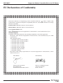
EU Declaration of Conformity
We declare that the accompanying product, identified with the “ ” mark, complies with
requirements of the Electromagnetic Compatibility Directive, 89/336/EEC and the Low Voltage
Directive 73/23/EEC.
Product Name: SMC100CC Motion Controller/Driver
Model Number: SMC100CC Motion Controller/Driver
Year
mark affixed: 2005
Type of Equipment: Electrical equipment for measurement, control and laboratory use.
Standards Applied:
Compliance was demonstrated to the following standards to the extent applicable:
EN 61326-1: 1997 “Electrical equipment for measurement, control and laboratory use - EMC
requirements”.
This equipment meets:
• EN 61000-4-3(96)+A1(98)+A2(2001)
• EN 61000-4-2(95)+A1(98)+A2(2001)
• EN 61000-4-6(96)+A1(2001)
• EN 61000-4-4(95)+A1(2001)
• EN 61000-4-5(95)+A1(2001)
• EN 61000-4-11(94)+A1(2001)
• EN 61000-3-3(95)+A1(2001)
• EN 61000-3-2(2000)
IEC 61010-1: 2001 “Safety requirements for electrical equipment for measurement, control
and laboratory use”.
EDH0206En1022 — 09/06
Alain Danielo
Dan Dunahay
VP European Operations
Zone Industrielle
45340 Beaune-la-Rolande, France
Director of Quality Systems
1791 Deere Avenue
Irvine, Ca. USA
vi
SMC100CC
Single-Axis Motion Controller/Driver for DC Motors
Preface
Confidentiality & Proprietary Rights
Reservation of Title
The Newport Programs and all materials furnished or produced in connection with them ("Related Materials") contain trade secrets of Newport and
are for use only in the manner expressly permitted. Newport claims and
reserves all rights and benefits afforded under law in the Programs provided by Newport Corporation.
Newport shall retain full ownership of Intellectual Property Rights in and to
all development, process, align or assembly technologies developed and
other derivative work that may be developed by Newport. Customer shall
not challenge, or cause any third party to challenge, the rights of Newport.
Preservation of Secrecy and Confidentiality and Restrictions to Access
Customer shall protect the Newport Programs and Related Materials as
trade secrets of Newport, and shall devote its best efforts to ensure that all
its personnel protect the Newport Programs as trade secrets of Newport
Corporation. Customer shall not at any time disclose Newport's trade
secrets to any other person, firm, organization, or employee that does not
need (consistent with Customer's right of use hereunder) to obtain access
to the Newport Programs and Related Materials. These restrictions shall
not apply to information (1) generally known to the public or obtainable
from public sources; (2) readily apparent from the keyboard operations,
visual display, or output reports of the Programs; (3) previously in the possession of Customer or subsequently developed or acquired without
reliance on the Newport Programs; or (4) approved by Newport for release
without restriction.
vii
EDH0206En1022 — 09/06
SMC100CC
Single-Axis Motion Controller/Driver for DC Motors
Sales, Tech Support & Service
North America & Asia
Europe
Newport Corporation
MICRO-CONTROLE
1791 Deere Ave.
Irvine, CA 92606, USA
1, rue Jules Guesde – Bât. B
ZI Bois de l’Épine – BP189
91006 Evry Cedex
France
Sales
(949) 253-1461 or (800) 222-6440 x31461
e-mail: [email protected]
Sales & Technical Support
+33 (0)1.60.91.68.68
Technical Support
e-mail: [email protected]
(949) 253-1406 or (800) 222-6440 x31406
e-mail: [email protected]
Service & Returns
+33 (0)2.38.40.51.55
Service, RMAs & Returns
(949) 253-1694 or (800) 222-6440 x31694
e-mail: [email protected]
Service Information
The user should not attempt any maintenance or service of the SMC100CC
Controller/Driver and its accessories beyond the procedures outlined in
this manual. Any problem that cannot be resolved should be referred to
Newport Corporation. When calling Newport regarding a problem, please
provide the Tech Support representative with the following information:
• Your contact information.
• System serial number or original order number.
• Description of problem.
• Environment in which the system is used.
• State of the system before the problem.
• Frequency and repeatability of problem.
• Can the product continue to operate with this problem?
• Can you identify anything that may have caused the problem?
Newport Corporation RMA Procedures
Any SMC100CC Controller/Driver being returned to Newport must have
been assigned an RMA number by Newport. Assignment of the RMA
requires the item serial number.
Packaging
SMC100CC Controller/Driver being returned under an RMA must be securely packaged for shipment. If possible, reuse the original factory packaging.
EDH0206En1022 — 09/06
viii
SMC100CC
Single-Axis Motion Controller/Driver for DC Motors
SMC100CC
Single-Axis Motion Controller/Driver for DC Motors
1.0
Safety Precautions
1.1
Definitions and Symbols
The following terms and symbols are used in this documentation and also
appear on the SMC100CC Controller/Driver where safety-related issues
occur.
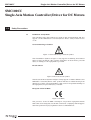
1.1.1
General Warning or Caution
Figure 1: General Warning or Caution Symbol.
The Exclamation Symbol in figure 1 may appear in Warning and Caution
tables in this document. This symbol designates an area where personal
injury or damage to the equipment is possible.
1.1.2
Electric Shock
Figure 2: Electrical Shock Symbol.
The Electrical Shock Symbol in Figure 2 may appear on labels affixed to the
SMC100CC Controller/Driver. This symbol indicates a hazard arising from
dangerous voltage. Any mishandling could result in irreparable damage to
the equipment, in personal injury, or death.
1.1.3
European Union CE Mark
Figure 3: CE Mark.
The presence of the CE Mark on Newport Corporation equipment means
that it has been designed, tested and certified as complying with all applicable European Union (CE) regulations and recommendations.
1
EDH0206En1022 — 09/06
SMC100CC
Single-Axis Motion Controller/Driver for DC Motors
1.2
Warnings and Cautions
The following are definitions of the Warnings, Cautions and Notes that may
be used in this manual to call attention to important information regarding
personal safety, safety and preservation of the equipment, or important
tips.
WARNING
Situation has the potential to cause bodily harm or death.
CAUTION
Situation has the potential to cause damage to property or
equipment.
NOTE
Additional information the user or operator should consider.
1.2.1
General Warnings and Cautions
The following general safety precautions must be observed during all phases of operation of this equipment.
Failure to comply with these precautions or with specific warnings elsewhere in this manual violates safety standards of design, manufacture, and
intended use of the equipment.
• Heed all warnings on the unit and in the operating instructions.
• To prevent damage to the equipment, read the instructions in this manual.
• Only plug the power supply to a grounded power outlet.
• Assure that the power supply is properly grounded to earth ground
through the grounding lead of the AC power connector
• Route power cords and cables where they are not likely to be damaged.
• Disconnect or do not plug in the AC power cord in the following circumstances:
– If the AC power cord or any other attached cables are frayed or damaged.
– If the power plug or receptacle is damaged.
– If the unit is exposed to rain or excessive moisture, or liquids are
spilled on it.
– If the unit has been dropped or the case is damaged.
– If the user suspects service or repair is required.
• Keep air vents free of dirt and dust.
• Keep liquids away from unit.
• Do not expose equipment to excessive moisture (>85% humidity)
• Do not operate this equipment in an explosive atmosphere.
• Disconnect power before cleaning the Controller/Driver unit. Do not use
liquid or aerosol cleaners.
• Do not open the SMC100CC Controller/Driver. There are no user-serviceable parts inside.
EDH0206En1022 — 09/06
2
SMC100CC
Single-Axis Motion Controller/Driver for DC Motors
• Return equipment to Newport Corporation for service and repair.
• Dangerous voltages associated with the 100-240 VAC power supply are
present inside the power supply. To avoid injury, do not touch exposed
connections or components while power is on.
• Follow precautions for static-sensitive devices when handling electronic
circuits.
2.0
System Overview
2.1
General Description
The SMC100CC is a single axis motion controller/driver for DC servo
motors up to 48 VDC at 1.5 A rms. It provides a very compact and low-cost
solution for driving a variety of Newport and other manufacturers motorized stages from a PC or from the optional SMC-RC remote control.
Communication with the SMC100CC is achieved via a RS-232-C, or from a
USB port using the external adapter SMC-USB (requires Windows™ operating system). A Windows based software supports all configurations and
enables basic motion. Advanced application programming is simplified by
an ASCII command interface and a set of two letter mnemonic commands.
When used with Newport ESP enhanced positioners, the SMC100CC will
detect the connected product automatically and provides easy configuration using the supplied Windows-based utility software. This exclusive
Newport feature reduces configuration time and provides the best protection of your equipment from any accidental damages.
Up to 31 controllers can be networked through the internal RS-485 communication link. This internal multi-drop full-duplex serial link simplifies communication to several units, without the need for sending “address selection commands”. This results in enhanced multi-axes management with
improved program readability and faster communication compared to
alternative systems based on a RS-232-C chain. The typical execution time
for a tell position command is only about 10 ms for the first controller and
only about 16 ms for the other controllers. The SMC100CC also features
advanced “multi-axes” commands such as “Stop all” or “start a motion of
all axes” and performs at a 57,600 baud rate communication speed.
Furthermore, for an efficient process control, the SMC100CC features dedicated digital outputs for "In Motion" and for "Not referenced".
2.2
Part Numbers
Product
Description
SMC100CC
Single-axis motion controller/driver for DC servo motors.
Includes 0.2 m long power and RS-485 cable.
SMC-RC
Remote control keypad for SMC100CC.
SMC-PS80
80 W power supply for SMC100CC.
SMC-232
RS-232-C cable, 3 m length (DB9F to DB9F).
SMC-USB
USB interface, Includes one USB to COM port adapter
and one RS-232-C cable.
Requires Windows™ operating system.
SMC-CB1
1 m RS-485 cable (only required when RS-485 cable supplied with SMC100CC is too short).
SMC-CB3
3 m RS-485 cable (only required when RS-485 cable supplied with SMC100CC is too short).
3
EDH0206En1022 — 09/06
SMC100CC
Single-Axis Motion Controller/Driver for DC Motors
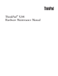
2.3
SMC100CC
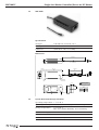
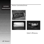
2.3.1
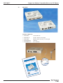
Contents of Delivery
• SMC100CC
• SMC-PSC0.2
• SMC-CB0.2
• SMC-MOTION
• SMC-MANUAL
Controller box
Power cable, 0.2 m length
RS-485 network cable, 0.2 m length
CD-Rom
User manual
C
0C
C10
SM
r
rive
r/D tors
olle
o
ontr r DC M
nC
fo
otio
M
xis
gle-A
Sin
SMC-MOTION
SMC100SetupV2.00
with LabVIEW™ driver
DOC0206FE0104 – 12/05
L
NUA
’S MA
USER WARE V2.0
FIRM
EDH0206En1022 — 09/06
4
SMC100CC
Single-Axis Motion Controller/Driver for DC Motors
2.3.2
2.3.3
Specifications
General Description
Single-axis motion controller/driver for DC servo
motors
Control Capability
DC servo motors, open or closed loop operation
Motor Output Power
– 48 VDC at 1.5 A rms, 3 A peak
– 100 kHz PWM switching frequency
Control loop
– Floating point digital PID loop with velocity and
friction feedforward
– 2 kHz servo rate
– Backlash compensation
Motion
Point-to-point motion with S-gamma profile and
jerk time control
Computer interface
– RS-232-C with 57,600 baud rate
– USB compatible with external adapter SMC-USB
(requires Windows™ operating system)
– RS-485 internal link for chaining up to 31 controllers from the same COM port
Programming
– 40+ intuitive, 2 letter ASCII commands
– Command set includes software limits, user
units, synchronized motion start, stop all
General purpose I/O
– 4 TTL out (open collector)
– 4 TTL in (2.21 kΩ pull up to 5 V)
– 1 analog input, ±10 V, 8-Bit
Dedicated inputs
– RS-422 differential encoder inputs for A, B, and I,
max. 2 MHz rate
– Forward and reverse limit, home switch and
index pulse
Dedicated outputs
– 1 open-collector output for “In Motion”
– 1 open collector output for “Not Referenced”
Status display
Two color LED
Internal safety feature
Watchdog timer
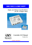
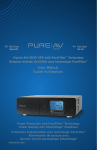
Dimensions
6.34
(161)
1.39
(35.3)
5.51
(140)
5
1.30
(33)
EDH0206En1022 — 09/06
SMC100CC
Single-Axis Motion Controller/Driver for DC Motors
2.4
SMC-RC
2.4.1
Specifications
General description
Remote control keypad for SMC100CC
Display
1 line x 16 characters LCD display for position and
short action description of Exec. button depending on controllers state
Function of push buttons (from left to right)
– Jog left
– High jog velocity (when pressed together with
jog left or jog right)
– Jog right
– Exec. (function as indicated in display depending
on controllers state)
Cable
2.4.2
0.5 m helix cable, both sides terminated
with RJ11-4/4 connectors
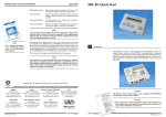
Dimensions
3.82
(97)
2.64
(67)
.98
(25)
EDH0206En1022 — 09/06
6
SMC100CC
Single-Axis Motion Controller/Driver for DC Motors
2.5
SMC-PS80
2.4.1
Specifications
2.4.2
AC Input
100–240 VAC, 47–63 Hz, 1.9 A
DC Output
48 V, 80 W max.
Connector
(male Ø 2.1 x Ø 5.5 x 11 mm)
Dimensions
44.5 1.0
1830+100/-0
SPT-1 18AWGx2C
AC INPUT
IEC 320 INLET
80 20(typ)
168.0 1.0
11
ID 2.1 x OD 5.5
4-
.
R4
5
POWER LED
Plug Assignment
22.25
R1
P2J
P/N
OUTPUT
CENTER
+
RUBBER FOOTX4
NAME PLATE
2.6
78.5 1.0
3
39.25
78.5 1.0
Standard plug: P2J (option)
System Environmental Specifications
Operating temperature 5 °C to 40 °C
Operating humidity
< 85% relative humidity, non-condensing
Storage temperature
0 °C to 60 °C
RH < 85% relative humidity, non-condensing
Installation category
II
Pollution degree
2
Use location
Indoor use only
7
EDH0206En1022 — 09/06
SMC100CC
Single-Axis Motion Controller/Driver for DC Motors
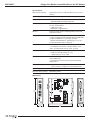
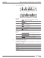
2.7
Connector Identification
Keypad
DC IN
RS232C
DC OUT
RS485
IN
RS485
OUT
GPIO
CONFIG.
LED
Motor
Front side
KEYPAD
RJ9F: For SMC-RC remote display and jog keypad.
Not functional for the moment.
RS-232-C
Sub-D9M: RS-232-C communication port for computer
communication
RS-485 IN
RJ11F: RS-485 input for chaining several SMC100CC in a
multi-drop configuration
RS-485 OUT
RJ11F: RS-485 output for chaining several SMC100CC in a
multi-drop configuration
CONFIG.
4 switches: Dip switches for communication setup
LED
LED: Status LED
Back side
2.8
DC IN
Ø 2.1 x Ø 5.5 x 11 mm: Power supply input (connect to
SMC80-PS)
DC OUT
Ø 2.1 x Ø 5.5 x 11 mm: Power supply repeater for connecting several SMC100CC to the same power supply
GPIO
Sub-D15F: General purpose inputs/outputs
MOTOR
Sub-D25F: Motor connection
Serial Communication Settings
Communication parameters are preset in the SMC100CC controller and do
not require any configuration:
EDH0206En1022 — 09/06
Bits per second
57,600
Data bits
8
Parity
None
Stop bits
1
Flow control
Xon/Xoff
Terminator
C L
R F
8
SMC100CC
3.0
Single-Axis Motion Controller/Driver for DC Motors
Getting Started
This section guides the user through the proper set-up of the SMC100CC
motion control system. When using the SMC100CC controller ONLY in local
control with the SMC-RC keypad and NOT from a computer, you can skip
this section and continue reading in section 4, SMC100CC with SMC-RC keypad. If not already done, carefully unpack and visually inspect the controllers and the stages for any damage. Place all components on a flat and
clean surface.
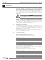
CAUTION
No cables should be connected to the controller at this point!
First, the controller must be configured properly. When using several
SMC100CC controllers from the same COM port through the internal RS-485
communication link, an individual address must be set for each controller.
Then, each controller must be configured to the connected stage. For both
steps, the software supplied with the SMC100CC is used.
3.1
SMC100CC Software Installation
The SMC100CC utility program (SMC100.exe) is designed to run on any
commercially available Pentium™ class desktop personal computer. The
computer should have a minimum of 64 MB of RAM. Newport recommends
using Windows XP™, or Windows 2000™.
For installation, put the CD in your CD drive and double-click on setup.exe.
Follow the instructions on the screen.
3.2
Communication Settings
3.2.1
RS-232-C Communication (Using SMC-232 Cable)
Apply the following settings to the COM port of your PC:
3.2.2
Bits per second
57,600
Data bits
8
Parity
None
Stop bits
1
Flow control
Xon/Xoff
Terminator
C L
R F
USB Communication (Using SMC-USB Interface)
Install the software supplied with the SMC-USB on your PC. Follow the
instructions supplied with the SMC-USB.
Apply the following settings to the COM port of your PC:
Bits per second
57,600
Data bits
8
Parity
None
Stop bits
1
Flow control
Xon/Xoff
Terminator
C L
R F
9
EDH0206En1022 — 09/06
SMC100CC
Single-Axis Motion Controller/Driver for DC Motors
3.3
Communication to a Single SMC100CC
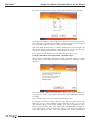
Set the dip switches on the SMC100CC to FIRST:
FIRST
ON
OFF
1 2 3 4
Connect the SMC100CC to the RS-232 or to the USB port of your PC.
Connect your stage to the SMC100CC (MOTOR connector). Connect the
power supply. The LED on the SMC100CC turns RED.
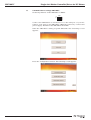
Start the SMC100CC utility program SMC.EXE. The following screen
appears:
Press the “Configuration” button. The following screen appears:
EDH0206En1022 — 09/06
10
SMC100CC
Single-Axis Motion Controller/Driver for DC Motors
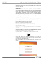
Press the “Communication setting” button. The following screen appears:
Select the port number of the COM port of your PC. Press the “Open” button. A message “Communication COM# is opened” appears on the screen. If
not, check the COM port settings of your PC and try again.
The input field “Refresh rate (s)” allows changing the screen refresh rate
used in the motion portal. Allowed values range from 0.1 s to 10 s. This setting can be changed only when the communication is closed.
Press “Back” button, which gets you back to the previous screen.
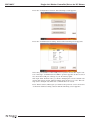
Using the SMC100CC with Newport ESP compatible stages
When using the SMC100CC with Newport ESP compatible stages (see label
on the stage), press “Stage parameters download”. The following screen
appears:
Press “Download”. When successful, after some seconds an according message appears on the screen and the status LED on the SMC100CC changes
to orange.
Your system is now correctly configured and ready to use.
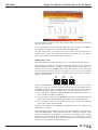
For testing, go back two screens, and press the “Motion portal” button. The
main user screen comes available. It has eight tabs at the top. Go to the
Tab “MOVE” and press the button “HOME”. Your stage should move to the
home position and the color of the status LED on the SMC100CC changes to
green. When done, enter in the field “Position 1” any allowed position of
your stage and press “GO”. Your stage should move to the commanded
11
EDH0206En1022 — 09/06
SMC100CC
Single-Axis Motion Controller/Driver for DC Motors
absolute position and the current position gets indicated in the position
field at the top of the screen. Your system is working correctly and you can
now try the other tabs.
Using the SMC100CC with not ESP compatible stages or changing the
default values
When using the SMC100CC with not ESP compatible stages, you need to
enter the stage parameters manually in the screen “Stage parameters modification”. This screen gets accessed from the “Configuration” screen. In the
“Stage parameter configuration” screen you can also change the configuration parameters stored in the controller. But it is not recommended doing
this unless you are an experienced user. For further information about the
meaning of the different parameters, please refer to the explanations at the
corresponding two letter commands named in brackets in section 5.5.
3.4
Communication to Several SMC100CC
When using several SMC100CC controllers through the internal RS-485 communication link, you need to follow specific steps to be successful:
Apply individual addresses to each controller.
Connect all elements of the system together.
Configure each controller to drive the connected stage.
3.4.1
Controller Address Setting
The first thing to do is applying an individual address to each SMC100CC
controller.
The address of the FIRST controller connected through RS-232-C remains
the address number 1. You don’t need to do anything with this controller.
For addressing the other controllers do the following:
Set the dip switches of ALL SMC100CC to FIRST (see graphic below).
FIRST
ON
OFF
1 2 3 4
Connect ONE, and only one, SMC100CC to the RS-232-C or to the USB port
of your PC. It is not needed to connect any stage to the controller. Connect
the power supply. The LED turns RED.
Start the SMC100CC utility program SMC.EXE. The following screen
appears:
EDH0206En1022 — 09/06
12
SMC100CC
Single-Axis Motion Controller/Driver for DC Motors
Press the “Configuration” button. The following screen appears:
Press the “Communication setting” button. The following screen appears:
Select the port number of the COM port of your PC. Press the “Open” button. A message “Communication COM# is opened” appears on the screen. If
not, check the COM port settings of your PC and try again.
The input field “Refresh rate (s)” allows changing the screen refresh rate
used in the motion portal. Allowed values range from 0.1 s to 10 s. This setting can be changed only when the communication is closed.
Press “Back” button, which gets you back to the previous screen. Press the
“Controller Address Setting” button and the following screen appears:
13
EDH0206En1022 — 09/06
SMC100CC
Single-Axis Motion Controller/Driver for DC Motors
Select an address and press the “Set” button. When successful, a message
appears on the screen.
It is recommended to note down the address of the controller somewhere.
For example, use the stickers supplied with the SMC100CC.
Now disconnect this controller from your PC and connect the next one
instead. Select a new, not yet allocated address and press the “Set” button
again. Proceed the same with all other controllers.
3.4.2
Building the System
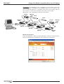
When the addresses of all controllers are set, you can build your system.
Pull out all cables from all controllers. Set the dip switches of the controller
with the address number 1 as FIRST. Set the dip switches of the other controllers, except one, as OTHERS, and set the dip switches of one controller
as LAST. When you have only two controllers, one has to be set as FIRST
(the one with the address number 1), and the other one as LAST. See below
graphic for illustration.
FIRST
RS232
OTHERS
RS485
LAST
RS485
1 2 3 4
1 2 3 4
1 2 3 4
ON
OFF
Connect the SMC100CC configured as FIRST to the RS-232-C port or to the
USB port of your PC. Connect a RS-485 network cable to the RS-485 OUT of
the FIRST controller and to the RS-485 IN of the next controller. Proceed the
same with all other controllers. When done, you can check your system:
• The controller configured as FIRST should have the RS-232-C cable connected. It has the address number 1.
• All controllers configured as OTHERS should have one RS-485 network
cable connected to the RS-485 IN and another one to the RS-485 OUT.
• The controller connected as LAST should have one RS-485 network
cable connected to the RS-485 IN.
Connect your stages to the SMC100CC’s (MOTOR connector). Connect your
SMC100CC’s to power.
The SMC100CC allows chaining power from one SMC100CC to another one
using the SMC-PSC0.2 cable supplied with the controller. But the total
power consumption of all stages connected to the same power supply
should not exceed 80 W. The maximum power consumption of each
Newport stage is listed in the Newport catalog and on the Newport web
site. In case of questions, contact Newport.
EDH0206En1022 — 09/06
14
SMC100CC
Single-Axis Motion Controller/Driver for DC Motors
An example: The maximum power consumption of a VP-25XA is 48 W. The
maximum power consumption of an LTA-HS is 6 W. So it is possible to connect one VP-25XA and up to 5 LTA-HS to the same power supply. But it is
not possible to connect two VP-25XA to the same power supply.
When done, your configuration should look as follow:
VP-25XA
SMC-PS80
LTA-HS
LTA-HS
SMC100CC
FIRST
VP-25XA
SMC-PS80
SMC-PS0.2
SMC-232
or
SMC-USB
SMC-PS0.2
SMC-CBx
SMC-CBx
SMC-CBx
3.4.3
SMC100CC
LAST
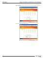
Enable all controllers
Start the SMC100CC utility program SMC.EXE, establish communication,
and press the Motion Portal button. The following screen appears:
15
EDH0206En1022 — 09/06
SMC100CC
Single-Axis Motion Controller/Driver for DC Motors
Go to the tab “Controllers”. Press the "Scan" button to validate all addressable controllers.
When done, press the “Apply” button.
EDH0206En1022 — 09/06
16
SMC100CC
Single-Axis Motion Controller/Driver for DC Motors
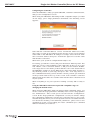
3.4.4
Configuring the Controller
Start the SMC100CC utility program SMC.EXE, establish communication,
and go to the Configuration screen.
When using the SMC100CC with Newport ESP compatible stages (see label
on the stage), press “Stage parameters download”. The following screen
appears:
Start with the controller address 1. Press “Download”. When successful,
after some seconds an according message appears on the screen and the
status LED on the SMC100CC #1 changes to orange. Select the next available controller address and press “Download” again. Proceed the same
with all other controllers.
When done, your system is configured and ready to use.
For testing, go back two screens, and press the button “Motion portal”. The
main user screen comes available. It has eight tabs at the top. Go to the
Tab “MOVE”, select controller address 1, and press the button “HOME”.
Your stage moves to the home position and the color of the status LED on
the SMC100CC changes to green. When done, enter in the field “Position 1”
any allowed position of your stage and press “GO”. Your stage moves to
the commanded absolute position and the current position gets indicated
in the position field at the top of the screen. Select another controller
address and do the same. Proceed the same with all other controllers used
in your system.
When everything is ok, your system is working correctly and is ready to
use.
Using the SMC100CC with non Newport ESP compatible stages or
changing the default values:
When using the SMC100CC with non Newport ESP compatible stages, you
need to enter the stage parameters manually in the screen “Stage parameters modification”. This screen gets accessed from the “Configuration”
screen. In the “Stage parameter configuration” screen you can also change
the configuration parameters stored in the controller. But it is not recommended doing this unless you are an experienced user. For further information about the meaning of the different parameters, please refer to the
explanations at the corresponding two letter commands (see command
names in brackets) in section 5.5.
17
EDH0206En1022 — 09/06
SMC100CC
4.0
Single-Axis Motion Controller/Driver for DC Motors
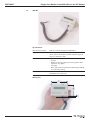
SMC100CC with SMC-RC Keypad
The SMC-RC keypad allows basic use of the SMC100CC controller without a
computer. It features a 16 characters position display and four push buttons for configuration, jogging, homing, and enabling/disabling motors. It
can be also used in parallel to a computer control.
If not already done, carefully unpack and visually inspect the SMC100CC
controller, the SMC-RC keypad, all stages and all accessories for any damage. Place all components on a flat and clean surface.
Connect the SMC-RC to the SMC100CC (KEYPAD connector).
Connect your stage to the SMC100CC (MOTOR connector).
Connect the SMC100CC to the SMC-PS80 (DC IN connector).
Connect the SMC-PS80 to power.
During the initialization, the SMC100CC controller checks if a SMC-RC keypad is connected. If so, it checks whether all buttons are open (not
pressed). If not, an error message gets generated.
NOTE
The SMC100CC does not recognize an SMC-RC after the initialization.
Also, disconnecting the SMC-RC from the controller and reconnecting
without reinitializing the controller does not work.
To reinitialize the SMC100CC controller, temporarily disconnect from
power and reconnect again, or send the RS command (see section 5.5).
When using the SMC100CC for the first time with a Newport ESP compatible
stage (see blue label on the product) a message AUTOCONFIG ?
YES
gets displayed for about 5 seconds. Press the Exec. button to configure the
SMC100CC to the connected stage. Once done, this message gets not displayed anymore during later initialization unless the SMC100CC recognizes
a different Newport ESP compatible stage than the one it is configured to.
This message gets also not displayed if the controller is already configured
correctly using the SMC100CC software utility (see section 3).
After successful initialization, the controller is in the NOT REFERENCED
state and the display displays +0.00000 HOM (for more details about the
SMC100CC states, please refer to section 5.1). Press the Exec. button to
home the stage. The stage starts moving to its home position. When done,
the display shows +0.00000 JOG. The digital value indicates the current
position of the stage. The default units for Newport positioners are millimeters for linear stages and actuators, and degrees for rotation stages.
Pressing the Exec. button again gets the controller to the JOGGING state
and the display changes to +0.00000 DIS. The jog buttons “<”, “<< >>”, and
“>” are now enabled. Pressing the “<” (jog left) or “>” (Jog right) button
starts a motion at slow velocity and with slow acceleration. Releasing the
button stops the motion. These slow speed motion are ideal for precise
adjustments. Pressing the “<” (jog left) or “>” (Jog right) button and the “<<
>>” (high speed) simultaneously starts a high speed motion. These high
speed motion are ideal for coarse adjustments. The jog speed and jog
acceleration settings are as follow:
EDH0206En1022 — 09/06
18
SMC100CC
Single-Axis Motion Controller/Driver for DC Motors
High jog velocity:
Equal to the default velocity (see value set in the
software utility or with the VA command).
High jog acceleration:
High jog velocity / 2s (means final velocity is
reached after 2 seconds).
High jog deceleration:
Equal to the default acceleration (see value set in
the software utility or with the AC command).
Low jog velocity:
Equal to the default velocity (see value set in the
software utility or with the VA command) divided
by 1000.
Low jog acceleration:
Low jog velocity / 2s (means final velocity is
reached after 2 seconds).
Low jog deceleration:
Equal to the default acceleration (see value set in
the software utility or with the AC command).
NOTE
Any jog motion always respects the software limits (see settings in the
software utility or with the SL and SR commands). When approaching a
software limit, the controller decelerates with the programmed acceleration even if the jog buttons are pressed.
Pressing the Exec. button when the three most right letters are DIS, gets
the controller to the DISABLE state. In DISABLE state the motor is not energized and the control loop is open. But the encoder is still read and the current position gets updated. The DISABLE state can be used for instance for
manual adjustments or to make sure that no energy goes to the motor. To
go from DISABLE state to the JOGGING state, press the Exec. button again.
The buttons of the keypad can get disabled by the JD command.
NOTE
The keypad does not allow stopping any motion started from a computer
(all buttons are disabled when the controller is in MOVING state). To
take computer control when the controller is in JOGGING state the controller must first get to the READY state (change state from the software
utility or by using the JD command).
19
EDH0206En1022 — 09/06
SMC100CC
5.0
Single-Axis Motion Controller/Driver for DC Motors
Programming
5.1
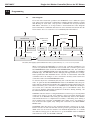
State Diagram
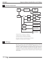
For a safe and consistent operation, the SCM100CC uses 7 different operation states: Not referenced, Configuration, Homing, Ready, Disable, Jogging
and Moving. In each state, only specific commands are accepted by the
SMC100CC. Therefore, it is important to understand the state diagram
below and which commands and actions cause transition between the different states. Also see section 5.5 for command/state information:
Following Error
Not Referenced
Exec. button*
Hardware Fault
Following
Error
PW1
Exec.
button*
PW0
OR
Exec.
button
Configuration
Following Error
Moving
Jogging
(<, > and << >> to change speed)
Disable
Done
MM1
PA/PR
JD*
MM0
Following Error
Exec. button
Done
Homing
Ready
* No action, when jogging speed is different than zero, e.g. one of the keys “<”, “>” or “<< >>” is pressed.
When connecting the SMC100CC to power, the controller initializes (see
section 5.2). When the initialization is successful, the controller gets to the
NOT REFERENCED state. From the NOT REFERENCED state, the controller
can go to the CONFIGURATION state with the PW1 command. In CONFIGURATION stage, the SMC100CC allows changing all stage and motor configuration parameters like maximum motor current or travel limits. The PW0
command saves all changes to the controller’s memory and returns the
controller back to the NOT REFERNCED state.
To execute any move commands (PA, PR), the controller must be in READY
state. To get from the NOT REFERENCED state to the READY state, the positioner must be homed first with the OR command. During homing (OR command execution), the controller is in HOMING state. When the homing is
successful, the controller automatically gets to the READY state. The
process for homing, and which signals are looked for during homing, can
be defined with the HT command.
In READY state the motor is energized and the control loop is closed (when
control loop state is closed, SC1). During a move execution (PA/PR), the
controller is in MOVING state and gets automatically back to the READY
state when the move is completed successfully. A following error during a
move changes the controller to DISABLE state. Other errors, for instance a
loss of the encoder signals, may change the controller to the NOT REFERENCED state.
In DISABLE state the motor is not energized and the control loop is open.
But the encoder is still read and the current position gets updated. The DISABLE state can be used for instance for manual adjustments or to make
sure that no energy goes to the motor. To go from READY state to DISABLE
state and vice versa, use the MM command.
EDH0206En1022 — 09/06
20
SMC100CC
Single-Axis Motion Controller/Driver for DC Motors
In JOGGING state the controller allows computer independent motion from
the SMC-RC keypad. The controller can get to the JOGGING state ONLY by
pressing the Exec. button on the SMC-RC when the controller is in the
READY or in the DISABLE state. To get from JOGGING state to READY state
use the JD command.
To get from READY state or DISABLE state back to the NOT REFERENCED
state, for instance to make some further parameter change in CONFIGURATION state, you need to reboot the controller with the RS command.
5.2
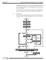
Initialization
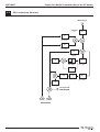
When connecting the SMC100CC to power, the following initialization routine gets executed. The initialization lasts less than 5 s. For more information about system errors during initialization, refer to the TS command in
section 5.5.
Reset
Hardware Initialization
Detect Keypad
Read Flash Setup
OK?
NO
ZX3?
NO
Read SmartStage
Keypad?
OK?
NO
NO
Display message
Same
NO
Initialize?
End of
Runs ?
NO
LED Blinking Orange
LED Continuous Orange
NO
LED Continuous Red
Initialize?
NO
Display message
End
21
EDH0206En1022 — 09/06
SMC100CC
Single-Axis Motion Controller/Driver for DC Motors
5.3
Command Syntax
The SMC100CC is a command driven controller. The general format of a
command is a two letter ASCII character preceded and followed by parameters specific to the command:
Command format:
nn AA xx
nn — Optional or required controller address.
AA — Command name.
xx — Optional or required value or “?” to query current value.
Both, upper and lower case characters are accepted. Depending on the
command, it can have an optional or required prefix (nn) for the controller
address and/or a suffix (xx) value or a “?”.
Blank spaces
Blanks are allowed and ignored in any position, including inside a numerical value. The following two commands are equivalent, but the first example might be confusing and uses more memory:
2P A1.43 6
2PA1.436
Decimal separator
A dot (“.”) is used as decimal separator for all numerical values.
Command terminator
Commands are executed as the command terminator CRLF (carriage-return
line-feed, ASCII 13 and ASCII 10) is received. The controller will analyze the
received string. If the command is valid and its parameters are in the specified range, it will be executed. Otherwise it will memorize an error.
After the execution of the command, all remaining characters in the input
string, if any, will be ignored. In particular, it is not possible to concatenate
several commands on a single string from the PC to the SMC100.
Each command will handle properly the memorization of related errors
that can be accessed with the TE command. Please refer to the command
set in section 5.5 for details.
5.4
Command Execution Time
The SMC100CC controller interprets commands continuously as received.
The typical execution time for a "tell position command" (nTP?) is about 10
ms for the first controller (controller address number 1) and about 16 ms
for the other controllers. Here, command execution time means the time
from sending the command until receive of the answer.
It is important to note that a move command, that may lasts for several
seconds, will not suspend the controller from further command execution.
So for an efficient process flow with many move commands it is recommended to use the PT command (get time for a relative move), and to
query the controller status (TS command) or the current position (TP command) before any further motion command is sent. Alternative, the dedicated outputs "In Motion" and "Not Referenced" can be used for similar
purposes. These will provide an even more timely accurate information of
the controller state.
EDH0206En1022 — 09/06
22
SMC100CC
Single-Axis Motion Controller/Driver for DC Motors
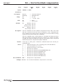
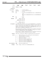
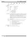
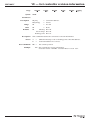
5.5
Command Set
This section describes the supported two-letter ASCII commands used to
configure and operate the SMC100CC. The general command format is:
Command format:
nn AA xx
nn — Optional or required controller address.
AA — Command name.
xx — Optional or required value or “?” to query current value.
Since multiple SMC100CC may be chained through the internal RS-485 Bus,
each controller uses a predetermined address (nn), and by decoding the
address field of the incoming commands, it can determine if the command
is intended for it. Some command though, can be passed without a controller address. In that case the command applies to all concerned controllers. For example: ST0 stops the motion on all controllers, 1ST0 stops
the motion only on controller #1.
Most commands can be used to set a value (in that case the command
name is followed by the value “xx”) or to query the current value (in that
case the command name is followed by a “?”). When querying a value, the
controller responds with the command it received followed by the queried
value. For example, a 1VA10 sets the velocity of the controller #1 to 10
units/second. A 1VA? sends the response 1VA10.
Not every command can be executed in all states of the SMC100CC and
some commands have different meaning in different states. It is therefore
important to understand the state diagram of the controller, see section
5.1.
23
EDH0206En1022 — 09/06
SMC100CC
Not Ref.
Single-Axis Motion Controller/Driver for DC Motors
Config.
Disable
Ready
Motion
Jogging
Description
AC
䊊
䊐
䊐
BA
䊊
Set/Get backlash compensation
BH
䊊
Set/Get hysteresis compensation
DV
䊊
Set/Get driver voltage
FD
䊊
䊐
Set/Get low pass filter for Kd
FE
䊊
䊐
Set/Get following error limit
FF
䊊
䊐
Set/Get friction compensation
HT
䊊
Set/Get HOME search type
ID
䊊
Set/Get stage identifier
Set/Get acceleration
䊉
JD
Leave JOGGING state
JM
䊊
䊐
䊐
Enable/disable keypad
JR
䊊
䊐
䊐
Set/Get jerk time
KD
䊊
䊐
Set/Get derivative gain
KI
䊊
䊐
Set/Get integral gain
KP
䊊
䊐
Set/Get proportional gain
KV
䊊
䊐
Set/Get velocity feed forward
䊉
MM
Set/Get HOME search velocity
䊉
Execute HOME search
䊊
OT
Set/Get HOME search time-out
䊉
PA
Move absolute
䊉
PR
䊉
PT
PW
Enter/Leave DISABLE state
䊊
OH
OR
䊉
䊉
䊉
Move relative
䊉
Get motion time for a relative move
䊉
Enter/Leave CONFIGURATION state
䊊
QI
Set/Get motor’s current limits
RA
䊉
䊉
䊉
䊉
䊉
䊉
Get analog input value
RB
䊉
䊉
䊉
䊉
䊉
䊉
Get TTL input value
䊉
䊉
䊉
䊉
RS
Reset controller
䊊
SA
SB
Set/Get controller’s RS-485 address
䊉
䊉
䊊
SC
Set/Get TTL output value
Set/Get control loop state
䊉
Configure/Execute simultaneous started move
SL
䊊
䊐
䊐
Set/Get negative software limit
SR
䊊
䊐
䊐
Set/Get positive software limit
䊉
䊉
䊉
SE
ST
Stop motion
䊊
SU
Set/Get encoder increment value
TB
䊉
䊉
䊉
䊉
䊉
TE
䊉
䊉
䊉
䊉
䊉
TH
䊉
䊉
䊉
䊉
䊉
䊉
Get set-point position
TP
䊉
䊉
䊉
䊉
䊉
䊉
Get current position
TS
䊉
䊉
䊉
䊉
䊉
䊉
Get positioner error and controller state
䊉
䊊
䊐
䊐
VE
䊉
䊉
䊉
䊉
䊉
ZT
䊉
䊉
䊉
䊉
䊉
VA
ZX
EDH0206En1022 — 09/06
䊉
Get command error string
Get last command error
Set/Get velocity
Get controller revision information
Get all axis parameters
䊊
Set/Get SmartStage configuration
24
SMC100CC
Single-Axis Motion Controller/Driver for DC Motors
Motion:
Corresponds to HOMING and MOVING state (for details see
state diagram, section 5.1).
䊊
Changes configuration parameters. Those changes will be
stored in the controller’s memory with the PW1 command and
remain available after switching off the controller.
䊐
Changes working parameters only. Those changes will get lost
when switching off the controller.
䊉
Accepted command.
Blank:
Not accepted command (will return an error).
Command: Command passed without preceding controller number
applies to all controllers (e.g. MM0 disables all controllers).
25
EDH0206En1022 — 09/06
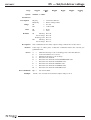
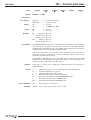
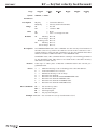
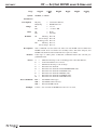
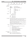
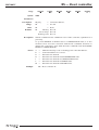
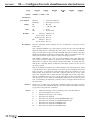
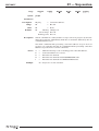
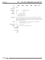
AC — Set/Get acceleration
SMC100CC
Usage
Syntax
Not Ref.
䊐
Config.
䊏
Disable
䊏
Ready
䊏
Motion
䊐
Jogging
䊐
xxACnn, or xxAC?
Parameters
Description
xx [int]
nn [float]
— Controller address.
— Acceleration value.
Range
xx
nn
— 1 to 31
— > 10-6 and < 1012
Units
xx
nn
— None
— Preset units/s2
Defaults
xx
Missing: Error B.
Out of range: Error B.
Floating point: Error A.
nn
Missing: Error C.
Out of range: Error C.
Description
In CONFIGURATION state, this command sets the maximum acceleration
value which can than be saved in the controller’s nonvolatile memory
using the PW command. This is the maximum acceleration that can be
applied to the mechanical system. It is also the default acceleration that
will be used for all moves unless a lower value is set in DISABLE or READY
state.
In DISABLE or READY state, this command sets the acceleration used for
the following moves. Its value can be up to the programmed value in CONFIGURATION state. This value is not saved in the controller’s memory and
will be lost after reboot.
Returns
Errors
Rel. Commands
Example
EDH0206En1022 — 09/06
If the sign “?” takes place of nn, this command returns the current programmed value.
A
B
C
D
H
L
M
—
—
—
—
—
—
—
VA —
Unknown message code or floating point controller address.
Controller address not correct.
Parameter missing or out of range.
Execution not allowed.
Execution not allowed in NOT REFERENCED state.
Execution not allowed in HOMING state.
Execution not allowed in MOVING state.
Set velocity.
1AC500 | Set controller #1 acceleration to 500 units/s2.
1AC? | Controller returns 1AC500.
26
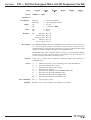
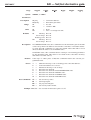
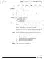
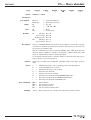
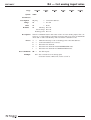
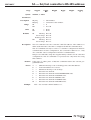
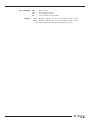
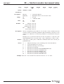
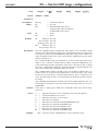
BA — Set/Get backlash compensation
SMC100CC
Usage
Syntax
Not Ref.
䊐
Config.
䊏
Disable
䊐
Ready
䊐
Motion
䊐
Jogging
䊐
xxBAnn, or xxBA?
Parameters
Description
xx [int]
nn [float]
— Controller address.
— Backlash value.
Range
xx
nn
— 1 to 31
— >= 0 and < 1E12
Units
xx
nn
— None
— Preset units
Defaults
xx
Missing: Error B.
Out of range: Error B.
Floating point: Error A.
nn
Missing: Error C.
Out of range: Error C.
Description
The BA command sets the backlash compensation value. This is the value
that the controller moves the motor in addition to the commanded distance with any move that reverses the direction of motion without changing the current position value (TP command).
The BA command helps compensating for repeatable mechanical defects
that appear when reversing the direction of motion, for instance mechanical play. The value 0 disables this function. This feature can be only used
when the hysteresis compensation (BH) is disabled.
Returns
Errors
Rel. Commands
If the sign “?” takes place of nn, this command returns the current programmed value.
A
B
C
D
H
J
K
L
M
—
—
—
—
—
—
—
—
—
BH —
Unknown message code or floating point controller address.
Controller address not correct.
Parameter missing or out of range.
Execution not allowed.
Execution not allowed in NOT REFERENCED state.
Execution not allowed in DISABLE state.
Execution not allowed in READY state.
Execution not allowed in HOMING state.
Execution not allowed in MOVING state.
Set hysteresis compensation.
Example 1BA0.005 | Set controller #1 backlash compensation to 0.005 units.
27
EDH0206En1022 — 09/06
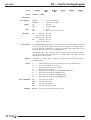
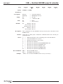
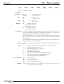
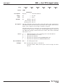
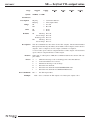
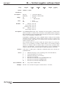
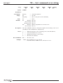
BH — Set/Get hysteresis compensation
SMC100CC
Usage
Syntax
Not Ref.
䊐
Config.
䊏
Disable
䊐
Ready
䊐
Motion
䊐
Jogging
䊐
xxBHnn, or xxBH?
Parameters
Description
xx [int]
nn [float]
— Controller address.
— Hysteresis value.
Range
xx
nn
— 1 to 31
— ≥ 0 and < 1012
Units
xx
nn
— None
— Preset units
Defaults
xx
Missing: Error B.
Out of range: Error B.
Floating point: Error A.
nn
Missing: Error C.
Out of range: Error C.
Description
The BH command sets the hysteresis compensation value. When set to a
value different than zero, the controller will issue for each move in the positive direction a move of the commanded distance plus the hysteresis compensation value, and then a second move of the hysteresis compensation
value in the negative direction. This motion ensures that a final position
gets always approached from the same direction and distance and helps
compensating for non-repeatable mechanical defects like hysteresis or
mechanical stiffness variations.
The value 0 disables this function. The BH command can not be used when
the backlash compensation is enabled (BA command).
Returns
Errors
Rel. Commands
If the sign “?” takes place of nn, this command returns the current programmed value.
A
B
C
D
H
J
K
L
M
—
—
—
—
—
—
—
—
—
BA —
Unknown message code or floating point controller address.
Controller address not correct.
Parameter missing or out of range.
Execution not allowed.
Execution not allowed in NOT REFERENCED state.
Execution not allowed in DISABLE state.
Execution not allowed in READY state.
Execution not allowed in HOMING state.
Execution not allowed in MOVING state.
Set backlash compensation.
Example 1BH0.015 | Set controller #1 backlash compensation to 0.015 units.
EDH0206En1022 — 09/06
28
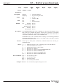
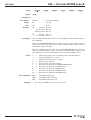
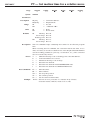
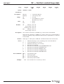
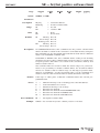
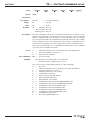
DV — Set/Get driver voltage
SMC100CC
Usage
Syntax
Not Ref.
䊐
Config.
䊏
Disable
䊐
Ready
䊐
Motion
䊐
Jogging
䊐
xxDVnn, or xxDV?
Parameters
Description
xx [int]
nn [float]
— Controller address.
— Driver voltage value.
Range
xx
nn
— 1 to 31
— ≥ 12 & ≤ 48
Units
xx
nn
— None.
— Volts
Defaults
xx
Missing: Error B.
Out of range: Error B.
Floating point: Error A.
nn
Missing: Error C.
Out of range: Error C.
Description
Returns
Errors
Rel. Commands
Example
This command sets the max. output voltage of the driver to the motor.
If the sign “?” takes place of nn, this command returns the current programmed value.
A
B
C
D
H
J
K
L
M
—
—
—
—
—
—
—
—
—
QI —
Unknown message code or floating point controller address.
Controller address not correct.
Parameter missing or out of range.
Execution not allowed.
Execution not allowed in NOT REFERENCED state.
Execution not allowed in DISABLE state.
Execution not allowed in READY state.
Execution not allowed in HOMING state.
Execution not allowed in MOVING state.
Set current limit.
1DV48 | Set controller #1 maximum output voltage to 48 V.
29
EDH0206En1022 — 09/06
SMC100CC
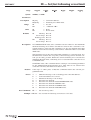
FD — Set/Get low pass filter cut off frequency for Kd
Usage
Syntax
Not Ref.
䊐
Config.
䊏
Disable
䊏
Ready
䊐
Motion
䊐
Jogging
䊐
xxFDnn, or xxFD?
Parameters
Description
xx [int]
nn [float]
— Controller address.
— Cut off frequency value.
Range
xx
nn
— 1 to 31
— > 10-6 and < 2000
Units
xx
nn
— None.
— Hertz
Defaults
xx
Missing: Error B.
Out of range: Error B.
Floating point: Error A.
nn
Missing: Error C.
Out of range: Error C.
Description
In CONFIGURATION state, this command sets the value for the low pass filter cut-off frequency which can than be saved in the controller’s nonvolatile memory using the PW command. It is also the default value that
will be used unless a different value is set in DISABLE state.
In DISABLE state, this command allows setting a new working parameter
for the low pass filter cut-off frequency. This value is not saved in the controller’s memory and will be lost after reboot.
Returns
Errors
Rel. Commands
If the sign “?” takes place of nn, this command returns the current programmed value.
A
B
C
D
H
K
L
M
—
—
—
—
—
—
—
—
SC —
Unknown message code or floating point controller address.
Controller address not correct.
Parameter missing or out of range.
Execution not allowed.
Execution not allowed in NOT REFERENCED state.
Execution not allowed in READY state.
Execution not allowed in HOMING state.
Execution not allowed in MOVING state.
Set closed loop state.
Example 1FD1500 | Set controller #1 Kd cut-off frequency to 1500 Hz.
EDH0206En1022 — 09/06
30
FE — Set/Get following error limit
SMC100CC
Usage
Syntax
Not Ref.
䊐
Config.
䊏
Disable
䊏
Ready
䊐
Motion
䊐
Jogging
䊐
xxFEnn, or xxFE?
Parameters
Description
xx [int]
nn [float]
— Controller address.
— Following error limit value.
Range
xx
nn
— 1 to 31
— > 10-6 and < 1012
Units
xx
nn
— None.
— Preset units.
Defaults
xx
Missing: Error B.
Out of range: Error B.
Floating point: Error A.
nn
Missing: Error C.
Out of range: Error C.
Description
In CONFIGURATION state, this command sets the value for the maximum
allowed following error which can than be saved in the controller’s nonvolatile memory using the PW command. It is also the default value that
will be used for the closed-loop control unless a different value is set in DISABLE state.
The following error is the most important parameter to control motion. It is
the difference between the set point (or theoretical) position and the current (or encoder) position. When the current following error exceeds the
maximum allowed value, a following error is issued and the controller is set
to DISABLE state.
In DISABLE state, this command allows setting a new working parameter
for the maximum allowed following error. This value is not saved in the
controller’s memory and will be lost after reboot.
Returns
Errors
Rel. Commands
If the sign “?” takes place of nn, this command returns the current programmed value.
A
B
C
D
H
K
L
M
—
—
—
—
—
—
—
—
SC —
Unknown message code or floating point controller address.
Controller address not correct.
Parameter missing or out of range.
Execution not allowed.
Execution not allowed in NOT REFERENCED state.
Execution not allowed in READY state.
Execution not allowed in HOMING state.
Execution not allowed in MOVING state.
Set closed loop state.
Example 1FE0.015 | Set controller #1 following error limit to 0.015 units.
31
EDH0206En1022 — 09/06
FF — Set/Get friction compensation
SMC100CC
Usage
Syntax
Not Ref.
䊐
Config.
䊏
Disable
䊏
Ready
䊐
Motion
䊐
Jogging
䊐
xxFFnn, or xxFF?
Parameters
Description
xx [int]
nn [float]
— Controller address.
— Friction compensation value.
Range
xx
nn
— 1 to 31
— ≥ 0 and < DV
Units
xx
nn
— None.
— Volt * second/preset units.
Defaults
xx
Missing: Error B.
Out of range: Error B.
Floating point: Error A.
nn
Missing: Error C.
Out of range: Error C.
Description
In CONFIGURATION state, this command sets the value for the friction compensation which can than be saved in the controller’s nonvolatile memory
using the PW command. It is also the default value that will be used for any
move unless a different value is set in DISABLE state.
The FF command helps minimizing the following error with systems that
have significant friction. The value for the friction compensation is the voltage that gets added to the output voltage whenever the set point (or theoretical) velocity is different from zero. The sign of this voltage is the same
as the sign of the set point velocity.
In DISABLE state, this command allows setting a new working parameter
for the friction compensation. This value is not saved in the controller’s
memory and will be lost after reboot.
Returns
Errors
Rel. Commands
Example
EDH0206En1022 — 09/06
If the sign “?” takes place of nn, this command returns the current programmed value.
A
B
C
D
H
K
L
M
—
—
—
—
—
—
—
—
SC —
Unknown message code or floating point controller address.
Controller address not correct.
Parameter missing or out of range.
Execution not allowed.
Execution not allowed in NOT REFERENCED state.
Execution not allowed in READY state.
Execution not allowed in HOMING state.
Execution not allowed in MOVING state.
Set closed loop state.
1FF0.15 | Set controller #1 friction compensation to 0.15 V * s/units.
32
HT — Set/Get HOME search type
SMC100CC
Usage
Syntax
Not Ref.
䊐
Config.
䊏
Disable
䊐
Ready
䊐
Motion
䊐
Jogging
䊐
xxHTnn, or xxHT?
Parameters
Description
xx [int]
nn [int]
— Controller address.
— Home type value.
Range
xx
nn
— 1 to 31
— 0 use MZ switch and encoder Index.
1 use current position as HOME.
2 use MZ switch only.
3 use EoR- switch and encoder Index.
4 use EoR- switch only.
Units
xx
nn
— None.
— None.
Defaults
xx
Missing: Error B.
Out of range: Error B.
Floating point: Error A.
nn
Missing: Error C.
Out of range: Error C.
Description
Returns
Errors
Rel. Commands
Example
This command sets the type of HOME search used with the OR command.
If the sign “?” takes place of nn, this command returns the current programmed value.
A
B
C
D
H
J
K
L
M
—
—
—
—
—
—
—
—
—
OR —
Unknown message code or floating point controller address.
Controller address not correct.
Parameter missing or out of range.
Execution not allowed.
Execution not allowed in NOT REFERENCED state.
Execution not allowed in DISABLE state.
Execution not allowed in READY state.
Execution not allowed in HOMING state.
Execution not allowed in MOVING state.
Execute HOME search.
1HT0 | Set controller #1 HOME sequence to use MZ and encoder index.
33
EDH0206En1022 — 09/06
ID — Set/Get stage identifier
SMC100CC
Usage
Syntax
Not Ref.
䊐
Config.
䊏
Disable
䊐
Ready
䊐
Motion
䊐
Jogging
䊐
xxIDnn, or xxID?
Parameters
Description
xx [int]
nn [float]
— Controller address.
— Stage model number.
Range
xx
nn
— 1 to 31
— 1 to 31 ASCII characters.
Units
xx
nn
— None
— None
Defaults
xx
Missing: Error B.
Out of range: Error B.
Floating point: Error A.
nn
Missing: Error C.
Out of range: Error C.
Description
The ID? command return the stage identifier. When used with Newport ESP
compatible stages (see blue label on the product), this is the identical to
the Newport product name. In CONFIGURATION mode, this command
allows changing the stage identifier. However, customer should never do
this when the ESP stage configuration is enabled (ZX3).
Returns
If the sign “?” takes place of nn, this command returns the current programmed value.
Errors
Rel. Commands
Example
EDH0206En1022 — 09/06
A
B
C
D
H
J
K
L
M
—
—
—
—
—
—
—
—
—
ZX —
Unknown message code or floating point controller address.
Controller address not correct.
Parameter missing or out of range.
Execution not allowed.
Execution not allowed in NOT REFERENCED state.
Execution not allowed in DISABLE state.
Execution not allowed in READY state.
Execution not allowed in HOMING state.
Execution not allowed in MOVING state.
Set SmartStage configuration.
1ID? | Get stage identifier for controller #1.
| Controller returns URS100CC.
34
JD — Leave JOGGING state
SMC100CC
Usage
Syntax
Not Ref.
䊐
Config.
䊐
Disable
䊐
Ready
䊐
Motion
䊐
Jogging
䊏
xxJD
Parameters
Description
xx [int]
— Controller address.
Range
xx
— 1 to 31
Units
xx
— None
Defaults
xx
Description
Errors
Rel. Commands
Example
Missing: Error B.
Out of range: Error B.
Floating point: Error A.
In JOGGING STATE, when no jog buttons are pressed and the stage velocity
is 0 the xxJD command sets the controller’s state to READY.
A
B
D
H
I
J
K
L
M
—
—
—
—
—
—
—
—
—
JM —
Unknown message code or floating point controller address.
Controller address not correct.
Execution not allowed.
Execution not allowed in NOT REFERENCED state.
Execution not allowed in CONFIGURATION state.
Execution not allowed in DISABLE state.
Execution not allowed in READY state.
Execution not allowed in HOMING state.
Execution not allowed in MOVING state.
Enable/Disable keypad.
1JD | Controller #1 leaves jogging state.
35
EDH0206En1022 — 09/06
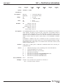
JM — Enable/Disable keypad
SMC100CC
Usage
Syntax
Not Ref.
䊐
Config.
䊏
Disable
䊏
Ready
䊏
Motion
䊐
Jogging
䊐
xxJMnn, or xxJM?
Parameters
Description
xx [int]
nn [float]
— Controller address.
— Jog state.
Range
xx
nn
— 1 to 31
— 0 or 1
Units
xx
nn
— None
— None
Defaults
xx
Missing: Error B.
Out of range: Error B.
Floating point: Error A.
nn
Missing: Error B.
Out of range: Error A.
Description
The JM1 command enables the SMC-RC keypad buttons (default setting).
The JM0 command disables the SMC-RC keypad buttons.
Sending the JM command when the controller is in DISABLE or READY
state only temporarily applies the setting. With the next boot of the controller the default setting will get applied again. Whereas sending the JM
command when the controller is in CONFIGURATION state saves the setting in the controller’s non-volatile memory).
Returns
Errors
Rel. Commands
Example
EDH0206En1022 — 09/06
If the sign “?” takes place of nn, this command returns the current programmed value.
A
B
D
H
L
M
—
—
—
—
—
—
JD —
Unknown message code or floating point controller address.
Controller address not correct.
Execution not allowed.
Execution not allowed in NOT REFERENCED state.
Execution not allowed in HOMING state.
Execution not allowed in MOVING state.
Leave JOGGING state.
1JM1 | Enable keypad for controller #1.
36
JR — Set/Get jerk time
SMC100CC
Usage
Syntax
Not Ref.
䊐
Config.
䊏
Disable
䊏
Ready
䊏
Motion
䊐
Jogging
䊐
xxJRnn, or xxJR?
Parameters
Description
xx [int]
nn [float]
— Controller address.
— Jerk time value.
Range
xx
nn
— 1 to 31
— > 0.001 and < 1012
Units
xx
nn
— None.
— Seconds.
Defaults
xx
Missing: Error B.
Out of range: Error B.
Floating point: Error A.
nn
Missing: Error C.
Out of range: Error C.
Description
In CONFIGURATION state, this command sets the value for the maximum
jerk time which can than be saved in the controller’s nonvolatile memory
using the PW command. It is also the default value that will be used unless
a different value is set in DISABLE or READY state.
Jerk is the derivative of acceleration. The jerk time defines the time to
reach the needed acceleration. A longer jerk time reduces stress to the
mechanics and smoothes motion.
In DISABLE or READY state, this command allows setting a new working
parameter for the maximum jerk time. This value is not saved in the controller’s memory and will be lost after reboot.
Returns
Errors
Rel. Commands
Example
If the sign “?” takes place of nn, this command returns the current programmed value.
A
B
C
D
H
L
M
—
—
—
—
—
—
—
AC —
Unknown message code or floating point controller address.
Controller address not correct.
Parameter missing or out of range.
Execution impossible (axis in movement).
Execution not allowed in NOT REFERENCED state.
Execution not allowed in HOMING state.
Execution not allowed in MOVING state.
Set positioner acceleration.
1JR0.05 | Set controller #1 jerk time to 0.05 seconds.
37
EDH0206En1022 — 09/06
KD — Set/Get derivative gain
SMC100CC
Usage
Syntax
Not Ref.
䊐
Config.
䊏
Disable
䊏
Ready
䊐
Motion
䊐
Jogging
䊐
xxKDnn, or xxKD?
Parameters
Description
xx [int]
nn [float]
— Controller address.
— Derivative gain value.
Range
xx
nn
— 1 to 31
— ≥ 0 and < 1012
Units
xx
nn
— None.
— Volt * second/preset unit.
Defaults
xx
Missing: Error B.
Out of range: Error B.
Floating point: Error A.
nn
Missing: Error C.
Out of range: Error C.
Description
In CONFIGURATION state, this command sets the derivative gain of the PID
control loop which can than be saved in the controller’s nonvolatile memory using the PW command. It is also the default value that will be used
unless a different value is set in DISABLE state.
In DISABLE state, this command allows setting a new working parameter
for the derivative gain. This value is not saved in the controller’s memory
and will be lost after reboot.
Returns
Errors
Rel. Commands
If the sign “?” takes place of nn, this command returns the current programmed value.
A
B
C
D
H
K
L
M
—
—
—
—
—
—
—
—
Unknown message code or floating point controller address.
Controller address not correct.
Parameter missing or out of range.
Execution not allowed.
Execution not allowed in NOT REFERENCED state.
Execution not allowed in READY state.
Execution not allowed in HOMING state.
Execution not allowed in MOVING state.
SC
KI
KP
KV
—
—
—
—
Set closed loop state.
Set integral gain.
Set proportional gain.
Set velocity feed forward.
Example 1KD0.015 | Set controller #1 derivative gain to 0.015.
EDH0206En1022 — 09/06
38
KI — Set/Get integral gain
SMC100CC
Usage
Syntax
Not Ref.
䊐
Config.
䊏
Disable
䊏
Ready
䊐
Motion
䊐
Jogging
䊐
xxKInn, or xxKI?
Parameters
Description
xx [int]
nn [float]
— Controller address.
— Integral gain value.
Range
xx
nn
— 1 to 31
— ≥ 0 and < 1012
Units
xx
nn
— None.
— Volt * preset unit/second.
Defaults
xx
Missing: Error B.
Out of range: Error B.
Floating point: Error A.
nn
Missing: Error C.
Out of range: Error C.
Description
In CONFIGURATION state, this command sets the integral gain of the PID
control loop which can than be saved in the controller’s nonvolatile memory using the PW command. It is also the default value that will be used
unless a different value is set in DISABLE state.
In DISABLE state, this command allows setting a new working parameter
for the derivative gain. This value is not saved in the controller’s memory
and will be lost after reboot.
Returns
Errors
Rel. Commands
If the sign “?” takes place of nn, this command returns the current programmed value.
A
B
C
D
H
K
L
M
—
—
—
—
—
—
—
—
Unknown message code or floating point controller address.
Controller address not correct.
Parameter missing or out of range.
Execution not allowed.
Execution not allowed in NOT REFERENCED state.
Execution not allowed in READY state.
Execution not allowed in HOMING state.
Execution not allowed in MOVING state.
SC
KD
KP
KV
—
—
—
—
Set closed loop state.
Set derivative gain.
Set proportional gain.
Set velocity feed forward.
Example 1KI0.015 | Set controller #1 integral gain to 0.015.
39
EDH0206En1022 — 09/06
KP — Set/Get proportional gain
SMC100CC
Usage
Syntax
Not Ref.
䊐
Config.
䊏
Disable
䊏
Ready
䊐
Motion
䊐
Jogging
䊐
xxKPnn, or xxKP?
Parameters
Description
xx [int]
nn [float]
— Controller address.
— Proportional gain value.
Range
xx
nn
— 1 to 31
— ≥ 0 and < 1012
Units
xx
nn
— None.
— Volt/preset unit
Defaults
xx
Missing: Error B.
Out of range: Error B.
Floating point: Error A.
nn
Missing: Error C.
Out of range: Error C.
Description
In CONFIGURATION state, this command sets the proportional gain of the
PID control loop which can than be saved in the controller’s nonvolatile
memory using the PW command. It is also the default value that will be
used unless a different value is set in DISABLE state.
In DISABLE state, this command allows setting a new working parameter
for the derivative gain. This value is not saved in the controller’s memory
and will be lost after reboot.
Returns
Errors
Rel. Commands
If the sign “?” takes place of nn, this command returns the current programmed value.
A
B
C
D
H
K
L
M
—
—
—
—
—
—
—
—
Unknown message code or floating point controller address.
Controller address not correct.
Parameter missing or out of range.
Execution not allowed.
Execution not allowed in NOT REFERENCED state.
Execution not allowed in READY state.
Execution not allowed in HOMING state.
Execution not allowed in MOVING state.
SC
KD
KI
KV
—
—
—
—
Set closed loop state.
Set derivative gain.
Set integral gain.
Set velocity feed forward.
Example 1KP0.015 | Set controller #1 proportional gain to 0.015.
EDH0206En1022 — 09/06
40
KV — Set/Get velocity feed forward
SMC100CC
Usage
Syntax
Not Ref.
䊐
Config.
䊏
Disable
䊏
Ready
䊐
Motion
䊐
Jogging
䊐
xxKVnn, or xxKV?
Parameters
Description
xx [int]
nn [float]
— Controller address.
— Velocity feed forward value.
Range
xx
nn
— 1 to 31
— ≥ 0 and < 1012
Units
xx
nn
— None.
— Volt * second/preset unit
Defaults
xx
Missing: Error B.
Out of range: Error B.
Floating point: Error A.
nn
Missing: Error C.
Out of range: Error C.
Description
In CONFIGURATION state, this command sets the velocity feed forward of
the PID control loop which can than be saved in the controller’s nonvolatile memory using the PW command. It is also the default value that
will be used unless a different value is set in DISABLE state.
In DISABLE state, this command allows setting a new working parameter
for the derivative gain. This value is not saved in the controller’s memory
and will be lost after reboot.
Returns
Errors
Rel. Commands
If the sign “?” takes place of nn, this command returns the current programmed value.
A
B
C
D
H
K
L
M
—
—
—
—
—
—
—
—
Unknown message code or floating point controller address.
Controller address not correct.
Parameter missing or out of range.
Execution not allowed.
Execution not allowed in NOT REFERENCED state.
Execution not allowed in READY state.
Execution not allowed in HOMING state.
Execution not allowed in MOVING state.
SC
KD
KI
KP
—
—
—
—
Set closed loop state.
Set derivative gain.
Set integral gain.
Set proportional gain.
Example 1KV0.015 | Set controller #1 velocity feed forward to 0.015.
41
EDH0206En1022 — 09/06
MM — Enter/Leave DISABLE state
SMC100CC
Usage
Syntax
Not Ref.
䊐
Config.
䊐
Disable
䊏
Ready
䊏
Motion
䊐
Jogging
䊐
[xx]MMnn, or xxMM?
Parameters
Description
xx [int]
nn [float]
— Controller address.
— Velocity feed forward value.
Range
xx
nn
— 0 to 31
— 0 changes state from READY to DISABLE.
1 changes state from DISABLE to READY.
Units
xx
nn
— None.
— None.
Defaults
xx
nn
Description
Missing: Change to 0.
Out of range: Error B.
Floating point: Error A.
Missing: Error C.
Out of range: Error C.
When the MM command is sent without preceding controller number or
the controller number is 0, the MM command gets executed on all controllers.
MM0 changes the controller’s state from READY to DISABLE. In DISABLE
state the control loop is open and the motor is not energized. The encoder,
though, is still read and the current position gets updated.
MM1 changes the controller’s state from DISABLE to READY. The controller’s set point position is set equal to its current position and the control loop gets closed (depending on the closed-loop state). The residual following error gets cleared from the buffer and the motor gets energized.
Returns
Errors
Rel. Commands
Example
EDH0206En1022 — 09/06
If the sign “?” takes place of nn, this command returns the current state.
A
B
C
D
H
I
L
M
—
—
—
—
—
—
—
—
PW —
Unknown message code or floating point controller address.
Controller address not correct.
Parameter missing or out of range.
Execution not allowed.
Execution not allowed in NOT REFERENCED state.
Execution not allowed in CONFIGURATION state.
Execution not allowed in HOMING state.
Execution not allowed in MOVING state.
Enter/leave CONFIGURATION state.
MM0 | All controllers go to DISABLE state.
42
OH — Set/Get HOME search velocity
SMC100CC
Usage
Syntax
Not Ref.
䊐
Config.
䊏
Disable
䊐
Ready
䊐
Motion
䊐
Jogging
䊐
xxOHnn, or xxOH?
Parameters
Description
xx [int]
nn [float]
— Controller address.
— HOME high velocity.
Range
xx
nn
— 1 to 31
— > 10-6 and < 1012
Units
xx
nn
— None.
— Preset units/s.
Defaults
xx
Missing: Error B.
Out of range: Error B.
Floating point: Error A.
nn
Missing: Error C.
Out of range: Error C.
Description
This command sets the maximum velocity used by the controller for the
HOME search.
Returns
If the sign “?” takes place of nn, this command returns the current programmed value.
Errors
Rel. Commands
Example
A
B
C
D
H
J
K
L
M
—
—
—
—
—
—
—
—
—
OR —
OT —
Unknown message code or floating point controller address.
Controller address not correct.
Parameter missing or out of range.
Execution not allowed.
Execution not allowed in NOT REFERENCED state.
Execution not allowed in DISABLE state.
Execution not allowed in READY state.
Execution not allowed in HOMING state.
Execution not allowed in MOVING state.
Execute HOME search.
Set HOME search time-out.
1OH50 | Set controller #1 HOME search velocity to 50 units/s.
43
EDH0206En1022 — 09/06
OR — Execute HOME search
SMC100CC
Usage
Syntax
Not Ref.
䊏
Config.
䊐
Disable
䊐
Ready
䊐
Motion
䊐
Jogging
䊐
xxOR
Parameters
Description
xx [int]
— Controller address.
Range
xx
— 1 to 31
Units
xx
— None.
Defaults
xx
Missing: Error B.
Out of range: Error B.
Floating point: Error A.
nn
Missing: Error C.
Out of range: Error C.
Description
This command starts the execution of the HOME search as defined by the
HT command.
When in NOT REFERENCED state, for instance after system start, any positioner must first get homed with the OR command before further motion
commands can get executed.
The OR command gets accepted only in NOT REFERENCED state and only
with no present hardware errors, except for end-of-run maybe. Refer to the
TS command to get more information on the possible hardware errors.
Errors
Rel. Commands
Example
EDH0206En1022 — 09/06
A
B
C
D
E
I
J
K
L
M
—
—
—
—
—
—
—
—
—
—
HT —
OH —
OT —
Unknown message code or floating point controller address.
Controller address not correct.
Parameter missing or out of range.
Execution not allowed.
home sequence already started.
Execution not allowed in CONFIGURATION state.
Execution not allowed in DISABLE state.
Execution not allowed in READY state.
Execution not allowed in HOMING state.
Execution not allowed in MOVING state.
Set HOME search type.
Set HOME search velocity.
Set HOME search time-out.
1OR | Execute HOME search with controller #1.
44
OT — Set/Get HOME search time-out
SMC100CC
Usage
Syntax
Not Ref.
䊐
Config.
䊏
Disable
䊐
Ready
䊐
Motion
䊐
Jogging
䊐
xxOTnn, or xxOT?
Parameters
Description
xx [int]
nn [float]
— Controller address.
— HOME time-out.
Range
xx
nn
— 1 to 31
— > 1 and < 103
Units
xx
nn
— None.
— Seconds
Defaults
xx
Missing: Error B.
Out of range: Error B.
Floating point: Error A.
nn
Missing: Error C.
Out of range: Error C.
Description
This command sets the time-out value for the HOME search. When the
HOME search does not finish successfully before this time elapses, the
HOME search will be aborted and an error gets recorded.
Returns
If the sign “?” takes place of nn, this command returns the current programmed value.
Errors
Rel. Commands
Example
A
B
C
D
H
J
K
L
M
—
—
—
—
—
—
—
—
—
HT —
OH —
OR —
Unknown message code or floating point controller address.
Controller address not correct.
Parameter missing or out of range.
Execution not allowed.
Execution not allowed in NOT REFERENCED state.
Execution not allowed in DISABLE state.
Execution not allowed in READY state.
Execution not allowed in HOMING state.
Execution not allowed in MOVING state.
Set HOME search type.
Set HOME search velocity.
Execute HOME search.
1OT2.2 | Set controller #1 HOME time-out to 2.2 seconds.
45
EDH0206En1022 — 09/06
PA — Move absolute
SMC100CC
Usage
Syntax
Not Ref.
䊐
Config.
䊐
Disable
䊐
Ready
䊏
Motion
䊐
Jogging
䊐
xxPAnn, or xxPA?
Parameters
Description
xx [int]
nn [float]
— Controller address.
— New target position.
Range
xx
nn
— 1 to 31
— > SL and < SR
Units
xx
nn
— None.
— Preset units.
Defaults
xx
Missing: Error B.
Out of range: Error B.
Floating point: Error A.
nn
Missing: Error C.
Out of range: Error C.
Description
The PA command initiates an absolute move. When received, the positioner will move, with the predefined acceleration and velocity, to the new target position specified by nn.
The PA command gets only accepted in READY state, AND when the new
target position is higher or equal to the negative software limit (SL), AND
lower or equal to the positive software limit (SR).
To avoid any mismatch, the controller always rounds the new target position to the closest encoder position.
Returns
Errors
Rel. Commands
Example
EDH0206En1022 — 09/06
If the sign “?” takes place of nn, this command returns the target position
value.
A
B
C
D
G
H
I
J
—
—
—
—
—
—
—
—
Unknown message code or floating point controller address.
Controller address not correct.
Parameter missing or out of range.
Execution not allowed.
Target position out of limits.
Execution not allowed in NOT REFERENCED state.
Execution not allowed in CONFIGURATION state.
Execution not allowed in DISABLE state.
PR
TH
TP
SU
—
—
—
—
Move relative.
Get set-point position.
Get current position.
Set encoder increment value.
1PA2.2 | Move positioner on controller #1 to absolute position 2.2 units.
46
PR — Move relative
SMC100CC
Usage
Syntax
Not Ref.
䊐
Config.
䊐
Disable
䊐
Ready
䊏
Motion
䊐
Jogging
䊐
xxPRnn, or xxPR?
Parameters
Description
xx [int]
nn [float]
— Controller address.
— Displacement.
Range
xx
nn
— 1 to 31
— > SL and < SR
Units
xx
nn
— None.
— Preset units.
Defaults
xx
Missing: Error B.
Out of range: Error B.
Floating point: Error A.
nn
Missing: Error C.
Out of range: Error C.
Description
The PR command initiates a relative move. When received, the positioner
will move, with the predefined acceleration and velocity, to a new target
position nn units away from the current target position.
The PR command gets only accepted in READY state, AND when the distance of the positioner to the end of runs is larger than the commanded
displacement.
To avoid any mismatch, the controller always rounds the new target position to the closest encoder position.
Returns
Errors
Rel. Commands
Example
If the sign “?” takes place of nn, this command returns the target position
value.
A
B
C
D
G
H
I
J
—
—
—
—
—
—
—
—
Unknown message code or floating point controller address.
Controller address not correct.
Parameter missing or out of range.
Execution not allowed.
Displacement out of limits.
Execution not allowed in NOT REFERENCED state.
Execution not allowed in CONFIGURATION state.
Execution not allowed in DISABLE state.
PA
TH
TP
SU
—
—
—
—
Move absolute.
Get set-point position.
Get current position.
Set encoder increment value.
1PR2.2 | Move positioner on controller #1 to a new position 2.2 units away
from the current target position.
47
EDH0206En1022 — 09/06
PT — Get motion time for a relative move
SMC100CC
Usage
Syntax
Not Ref.
䊐
Config.
䊐
Disable
䊏
Ready
䊏
Motion
䊏
Jogging
䊐
xxPTnn
Parameters
Description
xx [int]
nn [float]
— Controller address.
— Displacement.
Range
xx
nn
— 1 to 31
— > 10-6 and < 1012
Units
xx
nn
— None.
— Preset units.
Defaults
xx
Missing: Error B.
Out of range: Error B.
Floating point: Error A.
nn
Missing: Error C.
Out of range: Error C.
Description
The PT commands helps evaluating move times for an efficient program
flow.
When receiving the PT command, the controller returns the time, in seconds, necessary to execute a relative move of the displacement nn with the
current working parameters (velocity, acceleration, etc.). The controller
does not execute any motion.
Errors
Rel. Commands
Example
EDH0206En1022 — 09/06
A
B
C
D
H
I
—
—
—
—
—
—
Unknown message code or floating point controller address.
Controller address not correct.
Parameter missing or out of range.
Execution not allowed.
Execution not allowed in NOT REFERENCED state.
Execution not allowed in CONFIGURATION state.
PA
PR
TH
TP
SU
—
—
—
—
—
Move absolute.
Move relative.
Get set-point position.
Get current position.
Set encoder increment value.
1PT2.2 | Get time to move positioner on controller #1 by 2.2 units.
| Controller returns: 1PT0.25, means 0.25 seconds.
48
PW — Enter/Leave CONFIGURATION state
SMC100CC
Usage
Syntax
Not Ref.
䊏
Config.
䊏
Disable
䊐
Ready
䊐
Motion
䊐
Jogging
䊐
xxPWnn, or xxPW?
Parameters
Description
xx [int]
nn [float]
— Controller address.
— Velocity feed forward value.
Range
xx
nn
— 1 to 31
— 1: Go from NOT REFERENCED state to CONFIGURATION
state.
0: Go from CONFIGURATION state to NOT REFERENCED
state.
Units
xx
nn
— None.
— None.
Defaults
xx
Missing: Error B.
Out of range: Error B.
Floating point: Error A.
nn
Missing: Error C.
Out of range: Error C.
Description
PW1 changes the controller’s state from NOT REFERENCED to CONFIGURATION. In Configuration state all parameter settings are saved in the controller’s memory and remain available after switching off the controller. In
addition, some settings are only possible in CONFIGURATION state (e.g. set
drive voltage, set Backlash compensation, etc.).
PW0 checks all stage parameters, and if they are acceptable, saves them in
the flash memory of the controller. After that, it changes the controller’s
state from CONFIGURATION to NOT REFERENCED.
The execution of a PW0 command may take up to 10 seconds. During that
time the controller will not respond to any other command.
Returns
Errors
Rel. Commands
Example
If the sign “?” takes place of nn, this command returns the current state.
A
B
C
D
J
K
L
M
—
—
—
—
—
—
—
—
MM —
Unknown message code or floating point controller address.
Controller address not correct.
Parameter missing or out of range.
Execution not allowed.
Execution not allowed in DISABLE state.
Execution not allowed in READY state.
Execution not allowed in HOMING state.
Execution not allowed in MOVING state.
Enter/Leave DISABLE state.
1PW1 | Changes controller #1 to CONFIGURATION state.
49
EDH0206En1022 — 09/06
QI — Set/Get motor’s current limits
SMC100CC
Usage
Syntax
Not Ref.
䊐
Config.
䊏
Disable
䊐
Ready
䊐
Motion
䊐
Jogging
䊐
xxQILnn, xxQIRnn, xxQITnn, xxQIL?, xxQIR?, or xxQIT?
Parameters
Description
xx [int]
Lmm [float]
Rnn [float]
Tpp [float]
—
—
—
—
Range
xx
mm
nn
pp
— 1 to 31
— ≥ 0.05 and ≤ 3.0
— ≥ 0.05 and ≤ 1.5 and ≤ mm
— > 0.01 and ≤ 100
Units
xx
mm
nn
pp
—
—
—
—
Defaults
xx
None.
Amperes.
Amperes.
Seconds.
Missing: Error B.
Out of range: Error B.
Floating point: Error A.
mm
nn
pp
Description
Controller address.
Motor’s peak current limit.
Motor’s rms current limit.
Motor’s rms current averaging time.
Missing:
Missing:
Missing:
Out of range:
Error C.
Error C.
Error C.
Error C.
QIL: Sets the controller’s maximum or peak output current limit to the
motor. When the controller detects a higher current than the peak current
limit, it will generate a hardware error and a fault will be recorded.
QIR: Sets the controller’s rms output current limit to the motor. The rms
current limit must be lower than the peak current limit. When the controller’s output current exceeds the rms current limit, it will generate a
hardware error and a fault will be recorded.
QIT: Sets the controller’s averaging period for rms current calculation. In
general, the QIT command defines for how long time the actual motor current is allowed to exceed the rms output current limit.
Returns
Errors
Rel. Commands
If the sign “?” takes place of nn, this command returns the current programmed value.
A
B
C
D
H
J
K
L
M
—
—
—
—
—
—
—
—
—
DV —
Unknown message code or floating point controller address.
Controller address not correct.
Parameter missing or out of range.
Execution not allowed.
Execution not allowed in NOT REFERENCED state.
Execution not allowed in DISABLE state.
Execution not allowed in READY state.
Execution not allowed in HOMING state.
Execution not allowed in MOVING state.
Set driver input voltage.
Example 1QIL0.75 | Set controller #1 current limit to 0.75 A.
1QIR0.25 | Set controller #1 rms current limit to 0.25 A.
1QIT2.5 | Set controller #1 rms averaging period to 2.5 s.
EDH0206En1022 — 09/06
50
RA — Get analog input value
SMC100CC
Usage
Syntax
Not Ref.
䊏
Config.
䊏
Disable
䊏
Ready
䊏
Motion
䊏
Jogging
䊏
xxRA
Parameters
Description
xx [int]
— Controller address.
Range
xx
— 1 to 31
Units
xx
— None.
Defaults
xx
Description
Errors
Rel. Commands
Example
Missing: Error B.
Out of range: Error B.
Floating point: Error A.
The RA command returns the value of the ±10 volts analog input. The converter is a ±7 bits analog to digital converter with ±0.15 volts of maximum
offset and 5% full scale linearity. The resolution is 0.078125 volts.
A
B
D
H
I
—
—
—
—
—
SB —
Unknown message code or floating point controller address.
Controller address not correct.
Execution not allowed.
Execution not allowed in NOT REFERENCED state.
Execution not allowed in CONFIGURATION state.
Get TTL inputs.
1RA | Get controller axis #1 analog input.
| Controller returns: 1RA7.8125, means 7.8125 V.
51
EDH0206En1022 — 09/06
RB — Get TTL input value
SMC100CC
Usage
Syntax
Not Ref.
䊏
Config.
䊏
Disable
䊏
Ready
䊏
Motion
䊏
Jogging
䊏
xxRB
Parameters
Description
xx [int]
— Controller address.
Range
xx
— 1 to 31
Units
xx
— None.
Defaults
xx
Description
Missing: Error B.
Out of range: Error B.
Floating point: Error A.
The RB command returns the value of the TTL inputs. The returned decimal number represents the binary word made of all 4 inputs, where bit 0 is
input 1, bit 1 is input 2, bit 2 is input 3, and bit 3 is input 4.
The TTL input value is 1 when the corresponding voltage on the pin is larger than 2.4 volts, and it is 0 when the corresponding voltage is below 0.8
volt. When the voltage is between these two values, the result is unreliable
and can be 1 or 0.
Errors
Rel. Commands
Example
EDH0206En1022 — 09/06
A
B
D
H
I
—
—
—
—
—
RA —
Unknown message code or floating point controller address.
Controller address not correct.
Execution not allowed.
Execution not allowed in NOT REFERENCED state.
Execution not allowed in CONFIGURATION state.
Get analog input value.
1RB | Get TTL input value for controller #1.
| Controller returns: 1RB5, means input 0 and 2 are high, all others
are low.
52
RS — Reset controller
SMC100CC
Usage
Syntax
Not Ref.
䊏
Config.
䊏
Disable
䊏
Ready
䊏
Motion
䊏
Jogging
䊐
xxRS
Parameters
Description
xx [int]
— Controller address.
Range
xx
— 1 to 31
Units
xx
— None.
Defaults
xx
Description
Missing: Error B.
Out of range: Error B.
Floating point: Error A.
The RS command issues a hardware reset of the controller, equivalent to a
power-up.
To go from DISABLE or READY state to CONFIGURATION state, it is also
needed to first reset the controller with the RS command, and then to
change the controller’s state with the PW1 command from NOT REFERENCED to CONFIGURATION.
Errors
Example
A
B
D
H
I
L
M
—
—
—
—
—
—
—
Unknown message code or floating point controller address.
Controller address not correct.
Execution not allowed.
Execution not allowed in NOT REFERENCED state.
Execution not allowed in CONFIGURATION state.
Execution not allowed in HOMING state.
Execution not allowed in MOVING state.
1RS | Reset controller #1.
53
EDH0206En1022 — 09/06
SA — Set/Get controller’s RS-485 address
SMC100CC
Usage
Syntax
Not Ref.
䊐
Config.
䊏
Disable
䊐
Ready
䊐
Motion
䉰
Jogging
䊐
xxSAnn, or xxSA?
Parameters
Description
xx [int]
nn [int]
— Axis number.
— Controller’s axis number.
Range
xx
nn
— 1
— 2 to 31
Units
xx
nn
— None.
— None.
Defaults
xx
Missing: Error B.
Out of range: Error B.
Floating point: Error A.
nn
Missing: Error C.
Out of range: Error C.
Description
The SA command sets the controller’s RS-485 address. This address is
ONLY used when the controller is configured for RS-485 communication.
The SA command can only be sent to a controller configured for RS-232-C
communication. In this configuration, the controller’s address is 1. Only
one controller can be configured for RS-232-C communication.
Newport recommends using the supplied utility software for all controller
configurations. The SA command is of practical use only when not using
this software.
Returns
Errors
Example
EDH0206En1022 — 09/06
If the sign “?” takes place of nn, this command returns the current programmed value.
A
B
C
D
H
J
K
L
M
—
—
—
—
—
—
—
—
—
Unknown message code or floating point controller address.
Controller address not correct.
Parameter missing or out of range.
Execution not allowed.
Execution not allowed in NOT REFERENCED state.
Execution not allowed in DISABLE state.
Execution not allowed in READY state.
Execution not allowed in HOMING state.
Execution not allowed in MOVING state.
1SA3 | Set controller’s RS-485 address to 3.
54
SB — Set/Get TTL output value
SMC100CC
Usage
Syntax
Not Ref.
䊐
Config.
䊐
Disable
䊏
Ready
䊏
Motion
䊏
Jogging
䊏
xxSBnn, or xxSB?
Parameters
Description
xx [int]
nn [int]
— Controller address.
— TTL output value.
Range
xx
nn
— 1 to 31
— 0 to 15
Units
xx
nn
— None.
— None.
Defaults
xx
Missing: Error B.
Out of range: Error B.
Floating point: Error A.
nn
Missing: Error C.
Out of range: Error C.
Description
The SB command sets the value of the TTL outputs. The decimal number
nn represents thereby the binary word made of all 4 outputs, where bit 0 is
output 1, bit 1 is output 2, bit 2 is output 3, and bit 3 is output 4.
A 1 closes the open collector output transistor of the output. A 0 blocks the
open collector output transistor of the output.
Returns
Errors
Rel. Commands
Example
If the sign “?” takes place of nn, this command returns the current TTL outputs value.
A
B
C
D
H
I
—
—
—
—
—
—
RB —
Unknown message code or floating point controller address.
Controller address not correct.
Parameter missing or out of range.
Execution not allowed.
Execution not allowed in NOT REFERENCED state.
Execution not allowed in CONFIGURATION state.
Get TTL input value.
1SB3 | Close controller #1 TTL outputs 1 & 2 and open outputs 3 & 4.
55
EDH0206En1022 — 09/06
SC — Set/Get control loop state
SMC100CC
Usage
Syntax
Not Ref.
䊐
Config.
䊏
Disable
䊐
Ready
䊐
Motion
䊐
Jogging
䊐
xxSCnn, or xxSC?
Parameters
Description
xx [int]
nn [int]
— Controller address.
— Closed loop state.
Range
xx
nn
— 1 to 31
— 1: CLOSED loop control.
0: OPEN loop control.
Units
xx
nn
— None.
— None.
Defaults
xx
Missing: Error B.
Out of range: Error B.
Floating point: Error A.
nn
Missing: Error C.
Out of range: Error C.
Description
SC1 sets the controller to CLOSED loop control. This is the default.
SC0 sets the controller to OPEN loop control. Open loop control might be
useful for defining stage parameters like friction compensation or velocity
feed forward.
Returns
Errors
Rel. Commands
Example
EDH0206En1022 — 09/06
If the sign “?” takes place of nn, this command returns the current state.
A
B
C
D
H
J
K
L
M
—
—
—
—
—
—
—
—
—
Unknown message code or floating point controller address
Controller address not correct.
Parameter missing or out of range.
Execution not allowed.
Execution not allowed in NOT REFERENCED state.
Execution not allowed in DISABLE state.
Execution not allowed in READY state.
Execution not allowed in HOMING state.
Execution not allowed in MOVING state.
KD
KI
KP
KV
—
—
—
—
Set derivative gain.
Set integral gain.
Set proportional gain.
Set velocity feed forward.
1SC1 | Set controller #1 to closed loop control.
56
SMC100CC
SE — Configure/Execute simultaneous started move
Usage
Syntax
Not Ref.
䊐
Config.
䊐
Disable
䊐
Ready
䊏
Motion
䊐
Jogging
䊐
xxSEnn, or xxSE?, or SE
Parameters
Description
xx [int]
nn [float]
— Controller address.
— New target position.
Range
xx
nn
— 0 to 31
— > SL and < SR
Units
xx
nn
— None.
— Preset units.
Defaults
xx
Missing: Change to 0.
Out of range: Error B.
Floating point: Error A.
nn
Description
Missing: Error C.
Out of range: Error C.
The SE command allows starting a move on different controllers at the
same time.
The command xxSEnn sets a new target position for the controller nn. But
different than the PA command, the move does not get executed immediately, but only after receipt of an SE command without preceding controller
number and without following position value. When receiving the SE command, all controllers start a move to their new target position.
The xxSEnn command gets only accepted in READY state, AND when the
new target position is higher or equal to the negative software limit (SL),
AND lower or equal to the positive software limit (SR). To avoid any mismatch, the controller always rounds the new target position to the closest
encoder position.
The SE command should not be confused with a synchronized move. With
a synchronized move, all positioners start their motion simultaneously and
have velocities, accelerations and jerk times which are limited to a rate
which make all positioners start and complete their moves at the same
time. The emphasis here is that they all start AND stop at the same time.
The SE command starts a move on all controllers at the same time, but
each positioner moves with its individually defined velocity and acceleration. So naturally, the different positioners don’t complete their motion at
the same time.
Returns
Errors
If the sign “?” takes place of nn, this command returns the target position
value set by the SE command, which is not necessarily the same as the target position set by the PA command.
A
B
C
D
H
I
J
L
M
—
—
—
—
—
—
—
—
—
Unknown message code or floating point controller address.
Controller address not correct.
Parameter missing or out of range.
Execution not allowed.
Execution not allowed in NOT REFERENCED state.
Execution not allowed in CONFIGURATION state.
Execution not allowed in DISABLE state.
Execution not allowed in HOMING state.
Execution not allowed in MOVING state.
57
EDH0206En1022 — 09/06
Rel. Commands
Example
EDH0206En1022 — 09/06
PR
TH
TP
SU
—
—
—
—
Move relative.
Get set-point position.
Get current position.
Set encoder increment value.
1SE2.2 | Prepare controller #1 to move to absolute position 2.2 units.
2SE3.3 | Prepare controller #2 to move to absolute position 3.3 units.
SE | All controllers start their programmed move, if any.
58
SL — Set/Get negative software limit
SMC100CC
Usage
Syntax
Not Ref.
䊐
Config.
䊏
Disable
䊏
Ready
䊏
Motion
䊐
Jogging
䊐
xxSLnn, or xxSL?
Parameters
Description
xx [int]
nn [float]
— Controller address.
— Negative software limit.
Range
xx
nn
— 1 to 31
— > -1012 and ≤ 0
Units
xx
nn
— None.
— Preset units.
Defaults
xx
Missing: Error B.
Out of range: Error B.
Floating point: Error A.
nn
Missing: Error C.
Out of range: Error C.
Description
In CONFIGURATION state, this command sets the negative software limit
which can than be saved in the controller’s nonvolatile memory using the
PW command. It is also the default value that will be used unless a different
value is set in DISABLE or READY state.
In DISABLE or READY state, this command allows setting a new working
parameter for the negative software limit. It must be lower or equal to the
set-point position. This value is not saved in the controller’s memory and
will be lost after reboot.
The software limits are useful to limit the travel range of a positioner.
There is no possibility to disable software limits. For an almost infinite
motion, for instance with a rotation stage, set the lowest possible value,
which is: -2 147 000 000 * "encoder increment value" (see SU command). For
instance if the encoder increment value is 0,0005, this limit is -1 073 500.
Returns
Errors
Rel. Commands
Example
If the sign “?” takes place of nn, this command returns the current programmed value.
A
B
C
D
H
L
M
—
—
—
—
—
—
—
SR —
Unknown message code or floating point controller address.
Controller address not correct.
Parameter missing or out of range.
Execution not allowed.
Execution not allowed in NOT REFERENCED state.
Execution not allowed in HOMING state.
Execution not allowed in MOVING state.
Set positive software limit.
1SL-100 | Set controller #1 negative software limit to –100 units.
59
EDH0206En1022 — 09/06
SR — Set/Get positive software limit
SMC100CC
Usage
Syntax
Not Ref.
䊐
Config.
䊏
Disable
䊏
Ready
䊏
Motion
䊐
Jogging
䊐
xxSRnn, or xxSR?
Parameters
Description
xx [int]
nn [float]
— Controller address.
— Positive software limit.
Range
xx
nn
— 1 to 31
— ≥ 0 and < 1012
Units
xx
nn
— None.
— Preset units.
Defaults
xx
Missing: Error B.
Out of range: Error B.
Floating point: Error A.
nn
Missing: Error C.
Out of range: Error C.
Description
In CONFIGURATION state, this command sets the positive software limit
which can than be saved in the controller’s nonvolatile memory using the
PW command. It is also the default value that will be used unless a different
value is set in DISABLE or READY state.
In DISABLE or READY state, this command allows setting a new working
parameter for the positive software limit. It must be larger or equal to the
set-point position. This value is not saved in the controller’s memory and
will be lost after reboot.
The software limits are useful to limit the travel range of a positioner.
There is no possibility to disable software limits. For an almost infinite
motion, for instance with a rotation stage, set the largest possible value,
which is: 2 147 000 000 * "encoder increment value" (see SU command). For
instance if the encoder increment value is 0,0005, this limit is 1 073 500.
Returns
Errors
Rel. Commands
Example
EDH0206En1022 — 09/06
If the sign “?” takes place of nn, this command returns the current programmed value.
A
B
C
D
H
L
M
—
—
—
—
—
—
—
SL —
Unknown message code or floating point controller address.
Controller address not correct.
Parameter missing or out of range.
Execution not allowed.
Execution not allowed in NOT REFERENCED state.
Execution not allowed in HOMING state.
Execution not allowed in MOVING state.
Set negative software limit.
1SR100 | Set controller #1 positive software positive to 100 units.
60
ST — Stop motion
SMC100CC
Usage
Syntax
Not Ref.
䊐
Config.
䊐
Disable
䊏
Ready
䊏
Motion
䊏
Jogging
䊐
[xx]ST
Parameters
Description
xx [int]
— Controller address.
Range
xx
— 0 to 31
Units
xx
— None.
Defaults
xx
Description
Missing: Change to 0.
Out of range: Error B.
Floating point: Error A.
The ST command is a safety feature. It stops a move in progress by decelerating the positioner immediately with the acceleration defined by the AC
command until it stops.
The xxST command with preceding controller address stops a move in
progress on controller xx. The ST command without preceding controller
address stops the moves on ALL controllers.
Errors
Example
A
B
D
H
I
—
—
—
—
—
Unknown message code or floating point controller address.
Controller address not correct.
Execution not allowed.
Execution not allowed in NOT REFERENCED state.
Execution not allowed in CONFIGURATION state.
ST | Stop moves on all controllers.
61
EDH0206En1022 — 09/06
SU — Set/Get encoder increment value
SMC100CC
Usage
Syntax
Not Ref.
䊐
Config.
䊏
Disable
䊐
Ready
䊐
Motion
䊐
Jogging
䊐
xxSUnn, or xxSU?
Parameters
Description
xx [int]
nn [float]
— Controller address.
— Equivalent units to one encoder count.
Range
xx
nn
— 1 to 31
— > 10-6 and < 1012
Units
xx
nn
— None.
— Units.
Defaults
xx
Missing: Error B.
Out of range: Error B.
Floating point: Error A.
nn
Missing: Error C.
Out of range: Error C.
Description
The SU command sets the value for one encoder count. It defines also the
system of units for all other parameters like travel limits, velocities, accelerations, etc. Therefore, it is the first parameter to be defined for any positioner.
Example: For a positioner with an encoder resolution of 1 µm, the command xxSU0.001 sets 1 encoder count = 1 µm = 0.001 unit or 1 unit = 1 mm.
Returns
Errors
If the sign “?” takes place of nn, this command returns the current programmed value.
A
B
C
D
H
J
K
L
M
—
—
—
—
—
—
—
—
—
Unknown message code or floating point controller address.
Controller address not correct.
Parameter missing or out of range.
Execution not allowed.
Execution not allowed in NOT REFERENCED state.
Execution not allowed in DISABLE state.
Execution not allowed in READY state.
Execution not allowed in HOMING state.
Execution not allowed in MOVING state.
Example 1SU7.5e-6 | Set controller #1 encoder increment to 7.5 * 10-6 units.
EDH0206En1022 — 09/06
62
TB — Get command error string
SMC100CC
Usage
Syntax
Not Ref.
䊏
Config.
䊏
Disable
䊏
Ready
䊏
Motion
䊏
Jogging
䊏
xxTBnn
Parameters
Description
xx [int]
— Controller address.
xx
nn [char]
— 1 to 31
— Error code (refer to TE command).
Units
xx
— None.
Defaults
xx
Range
nn
Description
Errors
Rel. Commands
Example
Missing: Error B.
Out of range: Error B.
Floating point: Error A.
Missing: Returns explanation of current error.
Out of range: Error C.
The TB command returns a string that explains the meaning of the error
code nn (see TE command for complete list).
A
B
C
D
—
—
—
—
TE —
Unknown message code or floating point controller address.
Controller address not correct.
Parameter missing or out of range.
Execution not allowed.
Get error code.
1TB@ | Get explanation to error code @.
| Controller returns: 1TB@ No error, @ means no error.
63
EDH0206En1022 — 09/06
TE — Get last command error
SMC100CC
Usage
Syntax
Not Ref.
䊏
Config.
䊏
Disable
䊏
Ready
䊏
Motion
䊏
Jogging
䊐
xxTE
Parameters
Description
xx [int]
— Controller address.
Range
xx
— 1 to 31
Units
xx
— None.
Defaults
xx
Description
Missing: Error B.
Out of range: Error B.
Floating point: Error A.
The TE command returns the currently memorized error. When a command is not executable, it memorizes an error. This error can be read with
the TE command. After the execution of a TE command, the error buffer
gets erased and another TE command will return @, means no error. When
a new command error is generated before the previous command error is
read, the new command error will overwrite the current memorized error.
For a safe program flow it is recommended to always query the command
error after each command execution.
Errors
Rel. Commands
Example
A
B
D
—
—
—
TB —
Unknown message code or floating point controller address.
Controller address not correct.
Execution not allowed.
Get error string.
1TE | Get last error memorized on controller #1.
| Controller returns: 1TE@, means no error.
List of errors and corresponding strings (see TB command):
@ — No error.
A — Unknown message code or floating point controller address.
B — Controller address not correct.
C — Parameter missing or out of range.
D — Command not allowed.
E — Home sequence already started.
F
— ESP stage name unknown.
G — Displacement out of limits.
H — Command not allowed in NOT REFERENCED state.
I
— Command not allowed in CONFIGURATION state.
J
— Command not allowed in DISABLE state.
K — Command not allowed in READY state.
L — Command not allowed in HOMING state.
M — Command not allowed in MOVING state.
S
— Communication Time Out.
U — Error during EEPROM access.
EDH0206En1022 — 09/06
64
TH — Get set-point position
SMC100CC
Usage
Syntax
Not Ref.
䊏
Config.
䊏
Disable
䊏
Ready
䊏
Motion
䊏
Jogging
䊏
xxTH
Parameters
Description
xx [int]
— Controller address.
Range
xx
— 1 to 31
Units
xx
— None.
Defaults
xx
Description
Errors
Rel. Commands
Example
Missing: Error B.
Out of range: Error B.
Floating point: Error A.
The TH command returns the value of the set-point or theoretical position.
This is the position where the positioner should be. In MOVING state, the
set-point position changes according to the calculation of the motion profiler. In READY state, the set-point position is equal to the target position.
A
B
D
H
I
—
—
—
—
—
TP —
Unknown message code or floating point controller address.
Controller address not correct.
Execution not allowed.
Execution not allowed in NOT REFERENCED state.
Execution not allowed in CONFIGURATION state.
Get current position.
1TH | Get set-point position of controller #1.
| Controller returns: 1TH0, set-point position = 0 units.
65
EDH0206En1022 — 09/06
TP — Get current position
SMC100CC
Usage
Syntax
Not Ref.
䊏
Config.
䊏
Disable
䊏
Ready
䊏
Motion
䊏
Jogging
䊏
xxTP
Parameters
Description
xx [int]
— Controller address.
Range
xx
— 1 to 31
Units
xx
— None.
Defaults
xx
Description
Missing: Error B.
Out of range: Error B.
Floating point: Error A.
The TP command returns the value of the current position. This is the position where the positioner actually is according to his encoder value. In
MOVING state, this value always changes. In READY state, this value should
be equal or very close to the set-point and target position.
Together with the TS command, the TP command helps evaluating whether
a motion is completed.
Errors
Rel. Commands
Example
EDH0206En1022 — 09/06
A
B
D
H
I
—
—
—
—
—
TH —
Unknown message code or floating point controller address.
Controller address not correct.
Execution not allowed
Execution not allowed in NOT REFERENCED state.
Execution not allowed in CONFIGURATION state.
Get set-point position.
1TP | Get current position of controller #1.
| Controller returns: 1TP0, actual position = 0 units.
66
TS — Get positioner error and controller state
SMC100CC
Usage
Syntax
Not Ref.
䊏
Config.
䊏
Disable
䊏
Ready
䊏
Motion
䊏
Jogging
䊏
xxTS
Parameters
Description
xx [int]
— Controller address.
Range
xx
— 1 to 31
Units
xx
nn
— None.
— None.
Defaults
xx
Missing: Error B.
Out of range: Error B.
Floating point: Error A.
Description
The TS command returns the positioner error and the current controller
state.
Returns
The TS command returns six characters (1TSabcdef). The first four, a, b, c,
and d, represent the positioner’s error in hexadecimal, and the last two, e,
and f, represent the current controller’s state.
Because a positioner can have many errors at the same time, the positioner
errors are represented by 4 hexadecimals (a, b, c, and d), where each hexadecimal represents 4 bits. Each of these bits represents one error:
–
–
–
–
–
–
–
–
–
–
Digit d, bit 0: Negative end of run.
Digit d, bit 1: Positive end of run.
Digit d, bit 2: Peak current limit.
Digit d, bit 3: rms current limit.
Digit c, bit 0: Short circuit detection.
Digit c, bit 1: Following error.
Digit c, bit 2: Time out homing.
Digit c, bit 3: Bad ESP stage.
Digit b, bit 0: D.C. voltage too low.
Digit b, bit 1: 80 W output power exceeded.
For converting the value of the hexadecimals (a, b, c, and d) to binary, use
the following table:
F
E
D
C
B
A
9
8
7
6
5
4
3
2
1
0
1111
1110
1101
1100
1011
1010
1001
1000
0111
0110
0101
0100
0011
0010
0001
0000
For instance, the error map 0013 represents the following error: Short circuit detection, Negative end of run, and positive end of run.
67
EDH0206En1022 — 09/06
Controller states:
–
–
–
–
–
–
–
–
–
–
–
–
–
–
–
–
–
–
–
–
–
Errors
Rel. Commands
Example
EDH0206En1022 — 09/06
A
B
0A: NOT REFERENCED from reset.
0B: NOT REFERENCED from HOMING.
0C: NOT REFERENCED from CONFIGURATION.
0D: NOT REFERENCED from DISABLE.
0E: NOT REFERENCED from READY.
0F: NOT REFERENCED from MOVING.
10: NOT REFERENCED ESP stage error.
11: NOT REFERENCED from JOGGING.
14: CONFIGURATION.
1E: HOMING commanded from RS-232-C.
1F: HOMING commanded by SMC-RC.
28: MOVING.
32: READY from HOMING.
33: READY from MOVING.
34: READY from DISABLE.
35: READY from JOGGING.
3C: DISABLE from READY.
3D: DISABLE from MOVING.
3E: DISABLE from JOGGING.
46: JOGGING from READY.
47: JOGGING from DISABLE.
—
—
TE —
Unknown message code or floating point controller address.
Controller address not correct.
Get last error.
1TS | Get error and state of controller #1.
| Controller returns: 1TS00000A, no errors and NOT REFERENCED
from reset.
68
VA — Set/Get velocity
SMC100CC
Usage
Syntax
Not Ref.
䊐
Config.
䊏
Disable
䊏
Ready
䊏
Motion
䊐
Jogging
䊐
xxVAnn, or xxVA?
Parameters
Description
xx [int]
nn [float]
— Controller address.
— Velocity value.
Range
xx
nn
— 1 to 31
— > 10-6 and < 1012
Units
xx
nn
— None.
— Preset units/s.
Defaults
xx
Missing: Error B.
Out of range: Error B.
Floating point: Error A.
nn
Missing: Error C.
Out of range: Error C.
Description
In CONFIGURATION state, this command sets the maximum velocity value
which can than be saved in the controller’s nonvolatile memory using the
PW command. This is the maximum velocity that can be applied to the
mechanical system. It is also the default velocity that will be used for all
moves unless a lower value is set in DISABLE or READY state.
In DISABLE or READY state, this command sets the velocity used for the following moves. Its value can be up to the programmed value in CONFIGURATION state. This value is not saved in the controller’s memory and will be
lost after reboot.
Returns
Errors
Rel. Commands
Example
If the sign “?” takes place of nn, this command returns the current programmed value.
A
B
C
D
H
L
M
—
—
—
—
—
—
—
AC —
Unknown message code or floating point controller address.
Controller address not correct.
Parameter missing or out of range.
Execution not allowed.
Execution not allowed in NOT REFERENCED state.
Execution not allowed in HOMING state.
Execution not allowed in MOVING state.
Set positioner acceleration.
1VA50 | Set controller #1 velocity to 50 units/s.
69
EDH0206En1022 — 09/06
VE — Get controller revision information
SMC100CC
Usage
Syntax
Not Ref.
䊏
Config.
䊏
Disable
䊏
Ready
䊏
Motion
䊏
Jogging
䊏
xxVE
Parameters
Description
xx [int]
nn [string]
— Controller address.
— Action.
Range
xx
— 1 to 31
Units
xx
— None.
Defaults
xx
Description
Errors
Rel. Commands
Example
EDH0206En1022 — 09/06
Missing: Error B.
Out of range: Error B.
Floating point: Error A.
This command returns the controller’s revision information.
A
B
—
—
TP —
Unknown message code or floating point controller address.
Controller address not correct.
Get current position.
1VE | Get controller #1 revision information.
| Controller returns 1VE SMC - Controller-driver version 1.00r.
70
ZT — Get all configuration parameters
SMC100CC
Usage
Syntax
Not Ref.
䊏
Config.
䊏
Disable
䊏
Ready
䊏
Motion
䊏
Jogging
䊐
xxZT
Parameters
Description
xx [int]
— Controller address.
Range
xx
— 1 to 31
Units
xx
— None.
Defaults
xx
Description
Missing: Error B.
Out of range: Error B.
Floating point: Error A.
The ZT command returns the list of all current configuration parameters.
The ZT command allows a quick review of all current stage parameter and
simplifies the configuration of non Newport stages, for instance by using
Hyper Terminal file transfer.
Errors
Rel. Commands
A
B
—
—
TE —
Unknown message code or floating point controller address
Controller address not correct
Get error code.
Example
1ZT | Get controller #1 configuration data.
1PW1
1AC320.000000
1BA0.000000
…
1VA80.000000
1ZX3
1PW1
71
EDH0206En1022 — 09/06
ZX — Set/Get ESP stage configuration
SMC100CC
Usage
Syntax
Not Ref.
䊐
Config.
䊏
Disable
䊐
Ready
䊐
Motion
䊐
Jogging
䊐
xxZXnn, or xxZX?
Parameters
Description
xx [int]
— Controller address.
Range
xx
nn
— 1 to 31
— 1 disable ESP stage check.
2 update ESP stage information.
3 enable ESP stage check.
Units
xx
nn
— None.
— None.
Defaults
xx
Missing: Error B.
Out of range: Error B.
Floating point: Error A.
nn
Missing: Error C.
Out of range: Error C.
Description
The ZX command allows loading ESP stage data to the controller’s flash
memory and enables/disables ESP stage check during power-up. ESP refers
to Newport stages with an EEPROM (called ESP chip), that contains all
stage information like motor type, travel limits, maximum velocity, maximum acceleration, etc.
The command ZX2 reads the parameters from the ESP stage and saves
them to the controller’s flash memory. When using the SMC100CC controller with Newport ESP compatible stages this is the fastest way of doing
the stage configuration. When not using the Newport supplied utility software, just send the ZX2 command, and you’re done.
The command ZX3 enables the ESP stage check. When enabled, the controller checks at each power-up whether the connected stage is the same
as the one recorded in the controller flash memory. If not, it memorizes an
error. The ESP stage check is recommended with all Newport ESP compatible stages.
The command ZX1 disables the ESP stage check. When disabled, the controller will not check the connected stage and the stage reference is set to
UNKNOWN.
Returns
Errors
Example
EDH0206En1022 — 09/06
If the sign “?” takes place of nn, this command returns the current stage
reference.
A
B
C
D
H
J
K
L
M
—
—
—
—
—
—
—
—
—
Unknown message code or floating point controller address.
Controller address not correct.
Parameter missing or out of range.
Execution not allowed.
Execution not allowed in NOT REFERENCED state.
Execution not allowed in DISABLE state.
Execution not allowed in READY state.
Execution not allowed in HOMING state.
Execution not allowed in MOVING state.
1ZX? | Controller returns: 1ZXURS100CC, means URS100CC stage.
72
SMC100CC
6.0
Single-Axis Motion Controller/Driver for DC Motors
Connector Pinout
6.1
DC IN and DC OUT (Female Ø 2.1 x Ø 5.5 x 11 mm)
Pin #
Description
Center +48 VDC
Outer
6.2
RS-232-C (Male Sub-D9)
Pin #
5
9
6
6.3
1
Description
1
Shortet together with 4 and 6
2
TX
3
RX
4
Shortet together with 1 and 6
5
GND
6
Shortet together with 1 and 4
7
Shortet together with 8
8
Shortet together with 7
9
Not connected
RS-485 IN and RS-485 OUT (Female RJ11-6/6)
Pin #
6.4
GND
Description
1
GND
2
RX+
3
RX-
4
TX-
5
TX+
6
GND
Keypad (Female RJ9-4/4)
Pin #
73
Description
1
+12 VDC
2
Tx
3
Rx
4
GND
EDH0206En1022 — 09/06
SMC100CC
Single-Axis Motion Controller/Driver for DC Motors
6.5
GPIO (Female Sub-D15)
Pin #
1
9
15
6.6
8
Analog in
2
GND
3
OUT1 (Open collector)
4
OUT2 (Open collector)
5
OUT3 (Open collector)
6
OUT4 (Open collector)
7
GND
8
IN1 (2.21 kΩ pull up to 5 V)
9
IN2 (2.21 kΩ pull up to 5 V)
10
IN3 (2.21 kΩ pull up to 5 V)
11
IN4 (2.21 kΩ pull up to 5 V)
12
GND
13
In Motion (Open collector)
14
Not Referenced (Open collector)
15
GND
Motor (Female Sub-D25)
Pin #
1
14
25
EDH0206En1022 — 09/06
Description
1
13
74
Description
1
Not connected
2
Not connected
3
Not connected
4
Not connected
5
MOTOR+
6
MOTOR+
7
MOTOR-
8
MOTOR-
9
Not connected
10
Not connected
11
Not connected
12
Not connected
13
ZM
14
GND
15
VI
16
GVD
17
EoR+
18
EoR-
19
VA
20
VB
21
+5 V
22
GVD
23
/VA
24
/VB
25
/VI
SMC100CC
7.0
Single-Axis Motion Controller/Driver for DC Motors
Backlash Compensation
Round to
encoder
resoluton
PA or PR
command
input
Compensate
Backlash in
Target position
+
Profiler
-
PID
Driver
Round to
encoder
resoluton
Unit
Stage
Encoder position
Backlash
out
Current position
Backlash
out
Set point position
Set point velocity
Set point acceleration
Goal position
Goal velocity
Goal acceleration
Target position is read by PA command.
Current position is read by TP command.
Set-point position is read by TH command.
Encoder resolution is set/read by the SU command.
Backlash is set/read by the BA command.
8.0
ESP Stages
ESP refers to Newport stages with an EEPROM (ESP chip), that contains all
stage information like motor type, travel limits, maximum speeds, etc. The
SMC100CC is capable reading this information from the stage and can save
it to the controller’s flash memory. This minimizes the stage configuration
time and possible errors during configuration. The SMC100CC can also be
configured to confirm at each power-up that the connected stage is the
same as the one recorded in the controller’s memory, which is another
safety feature.
75
EDH0206En1022 — 09/06
SMC100CC
9.0
Single-Axis Motion Controller/Driver for DC Motors
PID Control Loop Structure
Motor voltage
Saturation
(V )
DV
FF
+
Friction
(V * s/unit)
+
+
+
KV
Feed forward
(V * s/unit)
KP
+
+
+
Proportional
(V/unit)
* Tb
+
KI
+
Saturation
0.5 * DV/KI
Integral
(V * unit/s)
* 1/z
+
-
* 1/Tb
FD
KD
Low pass filter
Dérivative
(V * s/unit)
* 1/z
+
Set point
velocity
-
Set point
position
FROM PROFILER
EDH0206En1022 — 09/06
76
Current position
FROM ENCODER
SMC100CC
10.0
Single-Axis Motion Controller/Driver for DC Motors
Maintenance and Service
10.1
Enclosure Cleaning
The SMC100CC Controller/Driver should only be cleaned with a lightly
damped cloth or sponge with a soapy water solution. Do not use an acetone or alcohol solution, this will damage the finish of the enclosure.
10.2
Obtaining Service
The SMC100CC Controller/Driver contains no user serviceable parts. To
obtain information regarding factory service, contact Newport Corporation
or your Newport representative. Please have the following information
available:
• Instrument model number (on front panel).
• Instrument serial number (on rear panel) or original order number.
• Description of the problem.
If the instrument is to be returned to Newport Corporation, you will be
given a Return Number, which you should reference in your shipping documents.
Complete a copy of the Service Form as represented on the next page and
include it with your shipment.
77
EDH0206En1022 — 09/06
SMC100CC
Single-Axis Motion Controller/Driver for DC Motors
Service Form
Your Local Representative
Tel.:
Fax:
Name:
Return authorization #:
(Please obtain prior to return of item)
Company:
Address:
Date:
Country:
Phone Number:
P.O. Number:
Fax Number:
Item(s) Being Returned:
Model #:
Serial #:
Description:
Reasons of return of goods (please list any specific problems):
EDH0206En1022 — 09/06
78
Visit Newport Online at:
www.newport.com
North America & Asia
Europe
Newport Corporation
MICRO-CONTROLE Spectra-Physics S.A
1791 Deere Ave.
Irvine, CA 92606, USA
1, rue Jules Guesde – Bât. B
ZI Bois de l’Épine – BP189
91006 Evry Cedex
France
Sales
Sales & Technical Support
(949) 253-1461 or (800) 222-6440 x31461
+33 (0)1.60.91.68.68
e-mail: [email protected]
e-mail: [email protected]
Technical Support
Service & Returns
(949) 253-1406 or (800) 222-6440 x31406
+33 (0)2.38.40.51.55
e-mail: [email protected]
Service, RMAs & Returns
(949) 253-1694 or (800) 222-6440 x31694
e-mail: [email protected]