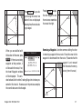
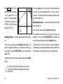
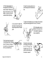
1
MAGELLAN
NAV 6500/NAV 6510 User Manual
© 1998 by Magellan Corporation. All rights reserved.
No part of this User Guide may be reproduced or transmitted in any form or by any means, electronic or mechanical, including
photocopying and recording, for any purpose other than the purchaser's personal use without the written permission of
Magellan Corporation.
Magellan™, GPS NAV 6500/ NAV 6510™ are the trademarks of Magellan Corporation.
Part No. 630323
Magellan NAV 6500/ NAV 6510 User Manual
WARNINGS
USE GOOD JUDGEMENT
This product is an excellent navigation aid, but does not replace the need for careful orienteering and good judgement. Never rely solely on
one device for navigating.
USE CARE
The Global Positioning System (GPS) is operated by the U.S. Government, which is solely responsible for its accuracy and maintenance.
The accuracy of position fixes can be affected by the periodic adjustments to GPS satellites made by the U.S. Government and is subject to
change in accordance with the Department of Defense civil GPS user policy and the Federal Radionavigation Plan.
USE CAUTION
Accuracy can be affected by poor satellite geometry. When accuracy warnings appear on the screen, use the data with extreme caution.
USE PROPER ACCESSORIES
Use only Magellan cables and antennas; the use of non-Magellan cables and antennas may severely degrade performance or damage the
receiver, and will void the warranty.
LICENSE AGREEMENT
Magellan grants you, the purchaser, the right to use the software supplied in and with MAGELLAN GPS products (the “SOFTWARE”) in the normal
operation of the equipment. You may make copies only for your own personal use and for use within your organization.
The SOFTWARE is the property of MAGELLAN and/or its suppliers and is protected by United States copyright laws and international treaty
provisions; therefore, you must treat this SOFTWARE like any other copyright material.
You may not use, copy, modify, reverse engineer or transfer this SOFTWARE except as expressly provided in this license. All rights not
expressly granted are reserved by MAGELLAN and/or its suppliers.
*
*
*
Contents
Introduction
Packing List ....................................................................... 1
Conventions Used in this Manual ...................................... 2
Commonly Used Terms ..................................................... 2
Getting Started
Magellan NAV 6500/NAV 6510 Description .................... 3
Power ON/OFF ................................................................ 5
Adjusting Contrast ............................................................ 5
Adjusting Backlighting ...................................................... 6
First Time Use - Initializing the Receiver ........................... 6
Navigating with Your Receiver ........................................... 8
Reference
General Usage .................................................................... 9
Turning the Receiver ON/OFF ......................................... 9
Cancelling an Operation .................................................... 9
Inputting Data .................................................................. 9
Adjusting Contrast ............................................................ 9
Adjusting Backlighting .................................................... 10
NAV Screens ................................................................... 10
Satellite Status Screen ................................................... 10
Map Screen .................................................................. 12
Setting the Map Scale ................................................... 13
Using the Cursor Key on the Map Screen .................... 13
Map Orientation .......................................................... 14
Track Plot Mode .......................................................... 15
Viewing Nav-Aid Attributes ......................................... 15
Finding Distance & Bearing from a Point on the Map . 17
Viewing Tide Information ............................................ 18
Viewing Port Information ............................................ 18
NAV 1 Screen .............................................................. 19
NAV 2 Screen .............................................................. 19
Customizing the Nav 2 Screen ..................................... 20
Waypoints ..................................................................... 20
Creating a Waypoint .................................................... 21
Saving the Cursor Position as a Waypoint .................... 21
Saving the Current Position Fix as a Waypoint ............. 21
Modifying Waypoint Data Fields ................................. 22
Creating a Waypoint Using the MARK key .................. 22
Accessing the Waypoint List ......................................... 23
Finding a Waypoint in the Waypoint List ..................... 23
Viewing a Waypoint from the Waypoint List ............... 24
Editing a Waypoint from the Waypoint List ................. 24
Deleting a Waypoint from the Waypoint List ............... 25
Deleting All Waypoints in the Waypoint List ............... 25
Creating a Waypoint from the Waypoint List ............... 25
Viewing Nearest Waypoint ........................................... 26
Deleting a Waypoint from the Map Screen .................. 26
Moving a Waypoint ..................................................... 26
Routes ........................................................................... 27
Creating a GOTO Route from Waypoint List .............. 27
Creating a GOTO Route from Nearest List ................. 28
Creating a GOTO Route by Waypoint Name .............. 28
Creating a GOTO Route to the Cursor Position .......... 29
Creating a MOB Route ................................................ 29
Deleting a GOTO Route ............................................. 29
Multi-leg Routes .......................................................... 30
Creating a Multi-Leg Route Using the Map ................. 30
Creating a Multi-Leg Route (Text Mode) ..................... 30
Activating a Route ........................................................ 31
Deactivating a Route .................................................... 32
Reversing a Route from the Map Screen ....................... 32
Reversing a Route from the List ................................... 33
Editing a Route ............................................................ 33
Inserting a Waypoint in a Route ................................... 33
Removing a Waypoint from a Route ............................ 34
Appending a Waypoint to the End of a Route .............. 34
Moving a Waypoint in a Route .................................... 35
Replacing a Waypoint in a Route Using Text Edit ........ 35
Activating a Leg of a Route .......................................... 36
Deleting a Route on the Map ....................................... 37
Deleting a Route in the List ......................................... 37
Copying a Route .......................................................... 37
Auxiliary Functions ........................................................ 38
The Aux Screen ............................................................ 38
General Setup Function ............................................... 38
Adjusting Contrast ....................................................... 39
Setting Time Reference ................................................ 39
Initializing Date/Time ................................................. 39
Setting Time Format .................................................... 40
Setting Date Format ..................................................... 40
Turning the Beeper On or Off ..................................... 40
Language Setting .......................................................... 40
Navigation Setup ......................................................... 41
Selecting Coordinate System ........................................ 41
Selecting Map Datum .................................................. 42
Selecting North Reference ............................................ 42
Selecting Map Orientation ........................................... 42
Setting Projected Course .............................................. 43
NAV 2 Screen Setup .................................................... 43
CDI/Units/Alarms Function ........................................ 43
Selecting CDI Scale ..................................................... 44
Setting Distance Units ................................................. 44
Setting Speed Units ...................................................... 44
Setting Depth Units ..................................................... 44
Activating Alarms ......................................................... 45
Setting Arrival Radius .................................................. 45
Setting Anchor Alarm .................................................. 45
Setting XTE Alarm ...................................................... 46
Turning Test Alarm On or Off ..................................... 46
Data Port Setup Functions ........................................... 46
Setting NMEA Output ................................................ 46
Changing NMEA Output Baud Rate ........................... 47
Turning NMEA Input On or Off ................................ 47
Changing NMEA Input Baud Rate .............................. 47
Setting Differential Input Baud Rate ............................ 47
Map Configuration Functions ...................................... 48
Turning Land Settings On and Off .............................. 48
Turning Marine Settings On and Off ........................... 48
Bathymetric Lines ........................................................ 49
Depth Areas Limit ....................................................... 49
Bathymetrics and Soundings Range ............................. 50
Turning Nav-Aid Settings On and Off ......................... 50
Lights ........................................................................... 51
Turning Other Settings On and Off ............................. 51
Turning Chart Settings On and Off ............................. 51
Plotter Mode ................................................................ 52
Track History Functions ............................................... 52
Turning Track History On or Off ................................. 53
Choosing Plotting Interval ........................................... 53
Resolution by Dist ....................................................... 53
Resolution by Time ...................................................... 53
Percentage of Track Memory Used ............................... 53
Clearing Track Memory ............................................... 54
Trip Planning Function ................................................ 54
Calculator .................................................................... 54
Calculating Sunrise/Sunset and Lunar Information ...... 55
Calculating Actual Current .......................................... 55
Simulation Mode Function .......................................... 56
Memory Reset .............................................................. 56
Color Setup .................................................................. 56
User C-Card ................................................................ 57
Map Shift ..................................................................... 58
Troubleshooting
Troubleshooting ........................................................... 60
Warnings/Alarms ......................................................... 62
Tutorial
Tutorial ........................................................................ 63
NAV 6500/NAV 6510 Appendix
Installation Instructions ................................................... 69
Gimbal Mount Installation Instructions ....................... 70
Flush Mount Installation Instructions .......................... 72
Proper Antenna Installation - Signal Reception ............ 74
Electrical Connections ................................................. 74
Wiring Instructions ...................................................... 75
Navaid Icons .................................................................... 76
Data Cartridges ............................................................... 81
List of Available Datums .................................................. 82
NMEA Messages ............................................................. 83
Abbreviations ................................................................... 90
Specifications ................................................................... 92
Coordinate Systems ......................................................... 93
What Is GPS? .................................................................. 95
Explanation of Data Terms .............................................. 97
Glossary ........................................................................... 99
Index
102
1
Intr
ntroduction
oduction
Congratulations on your purchase of the Magellan NAV 6500/
NAV 6510 receiver. The receiver integrates the remarkable
accuracy of a GPS receiver with a broad range of electronic
chart and navigation aids into a single easy-to-use navigation
information center.
Equipped with C-MAP CF-95 cartography, the receiver can
store up to 500 waypoints, and 25 routes with up to 50 legs.
The large LCD display features a help bar on every screen
and can be used either with cartography or as a track plotter
to monitor progress.
The manual is to be used with either the NAV 6500 or the
NAV 6510. These receivers differ in that the NAV 6510 is
the color version of the NAV 6500.
This manual is divided into six chapters; Introduction, Getting Started, Reference, Troubleshooting, Tutorial and Appendix. It is very important that you go through the Getting
Started chapter first as it prepares your receiver for use and
provides basic instruction. The third chapter is a Reference
Section for the features found in your receiver including stepby-step instructions on their use. Because of the advanced
navigational features of the receiver some of the terminology
Magellan NAV 6500/NAV 6510
used may be new to you. The Troubleshooting section gives
you a problem and answer series to guide you with problems
you may have. The fourth chapter is a Tutorial that walks you
through the basic usage of the receiver. The final chapter,
Appendix, contains some further explanations and information that will help you use your receiver and defines many of
the terms that may be unfamiliar.
Packing List
The following items should be in your package:
NAV 6500/NAV 6510 receiver
Remote antenna with 40 ft coax cable
Power/data cable
Gimbal mount kit
Plastic cover
Flush mount kit
Warranty card
If any of these items is missing, please contact your local
Magellan dealer or distributor.
1
Conventions Used in this Manual
The reference section of this manual is designed to assist you
in the use of your receiver. Each topic in the reference section
includes a brief description of the activity chosen, a pictorial
view of the keys to press, and a detailed description with sample
screens of how to perform the activity. As you become more
familiar with your receiver, you will be able to use the pictorial view of the keys as a "quick reference" to perform the
desired activity.
Also in the reference section are alerts to inform you of some
cautions or notes that will assist you in using your receiver.
The stop sign indicates information that is very
important and should be read before continuing.
The light bulb denotes information that can help
you use or understand your receiver. While this
information is not required to perform the activity,
it may provide you with a better understanding of
the activity or shortcuts you can use.
Commonly Used Terms
A few of the terms used in this manual may be unfamiliar to
you and are described in the Glossary found in the Appendix.
To help you get started, some of the more common terms are
described here with a simple explanation as to their meaning.
2
Position Fix: The receiver attains information from GPS satellites to compute a value (coordinates) that describes your
unique position on the earth. This is called taking a position fix and the coordinates computed are referred to as the
position fix.
Waypoint: (Abbreviated as WPT.) A position fix can be saved
in memory with a name and type that you either assign or
let the receiver assign for you. These saved position fixes are
called waypoints.
MARK: You can mark the cursor position or your present position at any time by pressing the MARK key to create a
waypoint.
GOTO: You can actually "Go To" a saved waypoint or any
cursor position simply by pressing the GOTO key and choosing a destination waypoint. The receiver will navigate you
from your present position to the waypoint chosen with
bearing and distance information.
Route: A route is slightly different from a GOTO. A route
contains a starting and ending waypoint and may include
intermediate waypoints along the way. Routes can be from
one waypoint to another (a single-leg route) or from a
waypoint to a series of waypoints, (a multi-leg route) up to
50 legs.
Leg: Legs are the divisions of a route between waypoints. A
route that goes from WPT A to WPT B, from WPT B to
WPT C, and from WPT C to WPT D has three legs.
Magellan NAV 6500/NAV 6510
Getting Star
Started
ted
This section shows you how to begin using your receiver for
the first time. After a brief description of the receiver, it discusses:
•
•
•
•
Turning power on and off
Adjusting contrast and backlighting
First time use, initializing the receiver
Navigating
Magellan NAV 6500/NAV 6510 Description
The Magellan GPS NAV 6500/NAV 6510 has a high contrast, high resolution backlit LCD, and backlit keypad and is
designed to be either flush-mounted or gimbal mounted.
Mount the unit as you plan on using it, install the antenna,
and make all the electrical and data connections before you
attempt to operate it. See the Installation section in the Appendix for details on mounting and connecting the receiver.
Keys
ZOOM IN - Changes the displayed map scale to view a
smaller area in greater detail.
Magellan NAV 6500/NAV 6510
2
ZOOM OUT - Changes the displayed map scale to view
a larger area in less detail.
CURSOR KEY - Controls cursor movement, and is used
to select menu items as well as scroll through the alphanumeric series for data entry. The UP/DOWN and
RIGHT/LEFT indicators on the CURSOR KEY move
the cursor or highlight in the cardinal directions, up,
down, right and left. The dots on the cursor key move
the cursor diagonally on the map display.
ENTER - Used to confirm data entry and confirm selections on the screen.
CTR - Centers the boat or cursor on the screen and allows toggling between the boat and the cursor position.
GOTO -Creates a one-leg route directly to the selected
waypoint or to the cursor position.
MARK - Records the present boat position or cursor position (if the map is displayed), as a stored waypoint.
ESC - Cancels and backs out of an operation or backs up
one step in a sequence.
3
Magellan NAV 6500/NAV 6510 GPS Receiver
ZOOM IN
ZOOM OUT
Display
Cursor Key
ENTER Key
CTR (Center) Key
GOTO Key
MARK Key
PWR (Power) and
Light Key
Softkeys
ESC (Escape) Key
Cartridge Slot
(not shown)
4
Magellan NAV 6500/NAV 6510
PWR - Turns the receiver on and off and adjusts the LCD
and keys backlight intensity.
SOFTKEYS - Softkey functions are accessed using the
keys along the bottom of the display. Softkey functions
appear at the bottom of each screen.
Power ON/OFF
To turn power on :
Press and release the PWR key.
The start-up screen and navigation warning screen are
displayed.
From the warning screen, press any key to exit and continue.
Information
Window
Map
To turn power off :
Press and hold down the PWR key.
Help
Bar
A countdown window is displayed on the screen. The
window will countdown from 3 to zero.
Continue to hold the PWR key until the countdown is
complete. The unit turns off.
Softkey
Functions
When the text of the softkey function is dark, the feature is
accessible; when the text is grayed out, the function is available from this screen but is not currently accessible.
Using the Help Bar. The map screen and many of the function screens contain a help bar, located just above the softkeys,
which tells you which action or actions you may perform on
the current screen.
Magellan NAV 6500/NAV 6510
Adjusting Contrast
Press the AUX softkey to access the AUXILIARY MENU
screen.
While “General Setup” is highlighted in the Auxiliary window, press ENTER to access the window at right, containing the CONTRAST option.
Use the CURSOR KEY to highlight CONTRAST and
press ENTER. A bar graph appears.
5
Use the RIGHT/LEFT arrows on the CURSOR KEY to adjust the contrast to a comfortable level, then press ENTER to
confirm.
Follow the instructions at the bottom of the screen, pressing
ESC twice to back out of the AUXILIARY screen.
Adjusting Backlighting
Adjust backlighting to three different levels of intensity by
pressing and releasing the PWR key repeatedly. The intensity
increases and decreases incrementally when the PWR key is
pressed.
First Time Use - Initializing the Receiver
The constellation of 24 GPS satellites circling the globe is in
constant motion and before your receiver can tell you where
you are, it needs to know where the satellites are relative to
itself. Your receiver’s internal almanac tells it which satellites
are in view at a given geographic position.
Therefore, you need to enter your approximate location, time
and date, which will serve as a point of reference for your
receiver in selecting the best satellites to use. Without knowing its approximate location, the receiver may take 10 minutes or more to find the specific coordinates of your position.
Telling your receiver the initial position, time and date is called
initializing your receiver; initializing enables it to begin track-
ing satellites, and therefore, calculating your position, much
faster.
You need not reinitialize your receiver each time
you use it, but only if the unit has moved over 300
miles without computing a postion or if the total
memory has been cleared by the user. If you do
not reinitialize, the receiver may take 10 minutes
or more to compute a new position fix.
Entering an Approximate Initial Position. To give your receiver an approximation of its current position, you will need
to enter the latitude and longitude of your general location.
The receiver allows you to enter the location quickly and
easily using the MAP screen.
While viewing the Satellite Status screen, press the INIT
POS softkey. The Map screen will appear.
Use the CURSOR KEY to move the cursor to your present
geographic area on this map. Use the ZOOM IN /ZOOM
OUT keys to help you determine whether the cursor is
active in the right part of the globe. (Some basic knowledge of continental land masses is helpful.)
If the cursor is not in your region of the world, press ZOOM
OUT repeatedly, then use the CURSOR KEY to move the
cursor to your present geographic area and use the ZOOM
IN key repeatedly to zero in on your present location.
When you have placed the cursor near your current loca-
6
Magellan NAV 6500/NAV 6510
tion, press ENTER, as you are instructed to do by the help
bar.
Now the help bar displays the word “Initializing...” and the
receiver returns to the Satellite Status screen.
The receiver records the coordinates of the cursor position
where ENTER was pressed as the starting point from which
it searches for available satellites. When it begins receiving
signals from satellites, this approximate coordinate position
will be updated to reflect your actual position.
Pressing the ESC key before initializing returns to the Satellite Status screen without changing the initial position.
Setting the Date and Time. To set the UTC date and time,
press the AUX soft key.
UTC, or Universal Time Coordinates, is simply
the current local time at the Prime Meridian
running through Greenwich, England. You must
calculate the local offset and enter the correct time
expressed in UTC for initializing your receiver.
(Be reminded that as you calculate your UTC you
need to correct for changes in your time zone due
to daylight savings time.)
Magellan NAV 6500/NAV 6510
While “General Setup” is highlighted in the
Auxiliary window, press ENTER to access the
window at right, containing the options, UTC
DATE and UTC TIME.
Use the CURSOR KEY to highlight UTC DATE and
press ENTER.
Use the CURSOR KEY to change the date to the current
UTC date, then press ENTER to confirm.
Use the CURSOR KEY to highlight UTC TIME and
press ENTER.
Use the CURSOR KEY to change the time to the current UTC time, then press ENTER to confirm.
Press ESC twice to return to the previously viewed NAV
screen.
In a few seconds, after being initialized, the receiver will acquire its first position fix, displaying the actual latitude and
longitude coordinates of your current position.
It is necessary to have a current position fix in
order for the receiver to compute navigation
information. If you do not have a position fix, the
navigation information will be displayed with
dashes until a position fix is acquired.
7
The format of the coordinates displayed can be changed. Latitude and longitude (LAT/LON) are expressed in ddd mm.ss,
ddd mm.mm or ddd mm.mmm. The first option uses seconds (there are 60 seconds to one minute of latitude or longitude), while the second and third options use decimal format. Other formats include: UTM, OSGB and TDs.
See Navigation Setup for instructions on changing the coordinate system.
Navigating with Your Receiver
Navigation requires setting waypoints and routes. You can
either create waypoints first, using the Waypoints softkey function, and then create routes using those waypoints, or go directly to the Routes function and connect the waypoints into
a route as you create them.
can also use the Nav 1 screen to get complete information on
your navigation such as position coordinates, DTG, BRG,
SOG, COG, VMG, TRN, TTG and ETA to the next destination waypoint. If you wish to use other parameters for navigation, you may customize the Nav 2 screen.
If you are not planning to monitor the receiver continuously,
you may choose to turn on certain alarms to warn you when
you are drifting off course or approaching your destination
waypoint.
The unit can also be connected to an autopilot. The steering
of the boat is then done automatically by the autopilot using
NMEA messages output by the unit.
Once the route is created, it must be activated. As you get
ready to navigate, make sure the boat icon representing your
present position is active (press CTR and the boat appears at
the center of your screen, press it again and the cursor is centered). Also, make sure that the unit is computing fixes, then
it is ready to update navigation information.
As you navigate, you can look at the map screen to see graphically how you are progressing and where you are with respect
to your planned route. You can view important navigation
data in the information window to the left of the map. You
8
Magellan NAV 6500/NAV 6510
3
Refer
eference
ence
General Usage
Turning the Receiver ON/OFF
To turn power on :
PWR
Press and release the PWR key.
The copyright and warning screens are displayed.
From the warning screen, press any key to exit and continue.
To turn power off :
PWR
Hold down until
countdown is finished.
A countdown window is displayed on the screen. The window will countdown from 3 to zero: POWERING DOWN
IN 3 Seconds.
Continue to hold the PWR key until the countdown is
complete. The unit turns off.
Magellan NAV 6500/NAV 6510
Cancelling an Operation
ESC
Use the ESC key to cancel and back out of an operation.
(except in setup)
Inputting Data
Use the CURSOR KEY to select menu items as well as
scrolling through alphanumeric series for data entry.
Use the UP/DOWN indicators on the CURSOR KEY to
scroll up and down through the alphanumeric list, stopping on the selection. Then use the RIGHT/LEFT indicators on the CURSOR KEY to move the highlight to the
right or left to continue or correct data entry.
Use ENTER to confirm data entry.
Adjusting Contrast
AUX
Highlight
Highlight
General Setup
Contrast
Press ENTER
Press ENTER
Adjust
Contrast
ENTER
9
Press the AUX softkey to access the AUXILIARY MENU
screen.
While “General Setup” highlighted in the Auxiliary window, press ENTER to access the window at right, containing the CONTRAST option.
Use the CURSOR KEY to highlight CONTRAST and
press ENTER.
A bar graph appears.
Use the RIGHT/LEFT arrows on the CURSOR KEY to
adjust the contrast to a comfortable level, then press ENTER to confirm.
Follow the instructions at the bottom of the screen, pressing ESC twice to back out of the AUXILIARY screen and
return to the last viewed root screen.
Adjusting Backlighting
Adjust backlighting to four different levels of intensity by pressing and releasing the PWR key repeatedly. The intensity increases and decreases incrementally when the PWR key is
pressed.
10
NAV Screens
The receiver has four different NAV screens that provide you
with information that you can use for navigating: SAT STATUS, MAP, NAV 1 and NAV 2.
From any NAV screen, press the Nxt Scrn soft key repeatedly
to cycle through the four NAV screens. The SAT STATUS
screen, MAP screen, NAV 1, and NAV 2 screens are constantly
updating and contain the information necessary to guide you
to your destination. You can customize the NAV 2 screen to
display the navigation information you find most useful (see
customizing).
Satellite Status Screen
The first screen after the navigation warning screen is the Satellite Status screen. This screen displays information relating
to the satellites being tracked, searched for, or used in the
position fix.
A bar graph shows the signal quality of the satellites being
tracked. The satellite identification numbers are shown along
the bottom of the graph, and the signal strength is shown
along the left edge. The longer the bar, the stronger the signal
of the corresponding satellite.
The satellites’ positions in the sky are plotted at right in 2
concentric circles representing 0° elevation at the horizon, and
45°. The center point of the circle, 90°, is directly overhead.
The satellites being tracked are shaded.
Magellan NAV 6500/NAV 6510
Jan/19/96
09:19:05AM
GPS Fix
Satellite Quality
Bar Graph
Satellite Position
(not tracking)
9
8
7
6
5
4
3
2
1
20
Satellite Position
(tracking)
01
14
Direction of
COG
25
15
29
Geometric Quality
22
01 14 15 20 21 22 25 29 -- --
Aux
Waypts
Routes
The current time, date, GPS status, geometric quality
(HDOP) and estimated position error (EPE) are also displayed. When the unit is first turned on, or when the position fix is more than 20 seconds old, the GPS status field will
indicate “Acquiring,” the HDOP and EPE numbers are replaced by underscores and the available softkeys are Aux,
Waypts, Routes, Init Pos, and Nxt Scrn.
Init Pos can be used to initialize the unit (see Entering an
Approximate Initial Position).
If the receiver is computing fixes and moving faster than 0.2
mph, a line from the center to the outer circle points in the
Magellan NAV 6500/NAV 6510
True North
HDOP:
1.1
EPE: 63.1Ft
Estimated Position
Error
MapShft NxtScrn
direction of COG. The direction of the line is updated whenever COG changes.
When the unit is computing fixes the GPS status field will
indicate “GPS Fix” and the active softkeys at the bottom of
the Satellite Status screen are Aux, Waypts, Routes, Map Shft
and Nxt Scrn.
If the boat’s position plotted on the map screen is
consistently offset from the coordinates plotted on
the paper chart, a bias may exist in the paper chart
due to the datum used. You can use Map Shift to
apply an offset to the boat’s position to correct for
the bias. See the section entitled Map Shift.
11
Map Screen
From the SAT STATUS screen, press Nxt Scrn to access the
Map Screen.
When the Map Screen is viewed for the first time after the
unit is turned on, the map always shows the cursor location
before the unit was turned off.
If the receiver is not yet initialized, the cursor
position defaults to 00°00.00 N and 00°00.00 E,
off the African coast in the Gulf of Guinea. See
Initializing.
On the left side of the screen, an information window displays the name of the destination waypoint of the active route
(if any), the distance and bearing from the present position to
the destination waypoint, the cartographic scale, and GPS
status, as well as COG, SOG, XTE and steering data if you
are moving.
Ten seconds after accessing the Map screen, the help bar disappears and the date and time are shown.
12
To Cursor
BRG 035`
M
n
DTG 6.7
m
COG 359`
SOG
7.0
XTE
TRN
M
k
t
--.---`
Los Angel
n
m
34`06'34"N
119`26'01"W
GPS Fix
Scale:
9 5 4 nm
03:07:21 PM
Aux
Waypts
Routes
Hide
NxtScrn
Press the Hide softkey to temporarily remove the information window, extending the map to the full screen width. Press
the Show softkey to redisplay the information window.
Magellan NAV 6500/NAV 6510
While the information window is hidden, press ESC to remove and deactivate the softkey labels, enlarging the map to
the dimensions of the entire display. Press ESC again or any
softkey to bring the softkey labels back into view.
N 34 00 00.00
Los Angel
Setting the Map Scale
ZOOM
IN
ZOOM
OUT
The map screen first appears in the highest possible scale setting. Use the ZOOM IN and ZOOM OUT keys to zero in
on a small area of the map or pan over a larger area.
The receiver retains the scale level last used when you go to
view other screens or when the receiver is turned off. If the
cartridge is changed, the screen will once again zoom to the
highest scale.
Map scale can also be changed from the Waypoint and Route
functions.
Using the Cursor Key on the Map Screen
N 32 00 00.00
Aux
Waypts
Routes
Show
NxtScrn
When the unit computes a fix, the present position will be
represented by a boat icon. If the position is more than 20
seconds old it is represented by the ( ) icon.
If the last computed fix is differentially corrected, the letter D
appears next to the GPS status.
Magellan NAV 6500/NAV 6510
Press the CURSOR KEY to activate and move the cursor
on the Map screen.
The cursor is represented by a + .
The information window displays the bearing and distance
from the present position (boat) to the cursor location (+),
the coordinates of the cursor, COG and SOG.
VMG and TTG are replaced by the cursor coordinates and
XTE and TRN are replaced by underscores.
13
While the cursor is active, press CTR to center the map around
the present position boat icon. Press CTR again to recenter
the display on the cursor.
If the boat and the cursor are shown on the screen, pressing
CENTER first centers the map around the present position
and removes the cursor icon, though it remains active. Pressing CENTER again centers the map around the cursor and
the present position boat icon is continuously updated.
When Track Up is selected, the map turns to keep the boat
icon pointing upwards. The top of the screen is then always
the COG direction. The map rotates every time the COG
changes more than the specified number of degrees set under
Aux functions (see Selecting Map Orientation, Auxiliary Functions).
If the map is centered on the boat, pressing the
CURSOR KEY will activate the cursor. If the
cursor was already active somewhere else on the
map and is not shown on the screen, that cursor
position is lost.
As you scroll across the map, the map will follow the cursor
movement when the cursor comes near the edge. The map
redraws with the cursor near the edge.
Los Angeles
Map Orientation
The map orientation can be set to North Up or Track Up.
When North Up is selected, the boat icon rotates according
to the COG direction with respect to north. The map on the
previous page is shown in North Up mode.
14
Aux
Waypts
Routes
Show
NxtScrn
Magellan NAV 6500/NAV 6510
Track Plot Mode
Track Plot Mode allows you to go where no man has gone
before - or at least where your chart does not provide detailed
navigation information - by displaying a LAT/LON grid without background cartography.
Though you can use this feature to plot and
retrace your course conveniently using coordinates
alone, EXTREME CAUTION IS REQUIRED
when using the Track Plot Mode. The Track Plot
Mode should never be used as a sole means of
navigation. Paper charts are required.
If a cartridge is not installed, zooming into a scale not supported by the built-in map activates the Track Plot mode. If a
cartridge is installed, zooming into a scale not supported by
either the cartridge or the internal map also activates the Track
Plot mode.
In this mode, the LAT/LON grid and label are turned on
automatically, even if they are off in the Map Configuration
and a warning appears for two seconds to let you know you
have zoomed to a scale not supported by cartography.
Track Plot Mode then plots the route you are traveling on a
grid showing coordinates, without background cartography.
Viewing Nav-Aid Attributes
Map objects appear as icons on the map. The
Nav-Aids (buoys, lights, signals, etc.) and other objects are
part of the cartography such as rocks, wrecks, etc. See Appendix for a list of map objects.
Object attributes appear instantly on the map screen in a
QUICK INFO window when the cursor covers an icon, giving a description of the object or objects. The abbreviated
description is similar in format and content to what you would
see in a standard paper chart.
To Cursor
BRG 035`
M
D T G 7 0 6 1 . nm
COG 164`
SOG
0.9
XTE
TRN
U n d e r w a t e r ro c k
M
k
h
--.---`
33`20'66"N
117`31'94"W
GPS Fix
Scale:
6
n
m
Use Cursor & ENT to set reference pnt
Aux
Magellan NAV 6500/NAV 6510
Waypts
Routes
Hide
NxtScrn
15
Press ENTER and the softkeys Expand, All Info, LocPort and
Set Ref become active. To view additional information on the
Objects shown in the QUICK INFO window, press ENTER
and a full-screen window opens, showing a list of the objects
under the cursor.
To Cursor
BRG 035`
M
n
DTG 7061.
m
COG 164`
SOG
0.9
XTE
TRN
Object:
Underwater rock
Navigational aid, generic
Underwater rock
M
k
h
--.---`
Use Cursor to scroll: ENT to select
33`20'66"N
117`31'94"W
GPS Fix
Scale:
6
n
m
Use Cursor & ENT to set reference pnt
Expand
All Info LocPort
Set Ref
When the ENTER key is pressed, the objects now appear in
the form of a menu. Use the CURSOR KEY to highlight an
object on the menu and press ENTER. For example, to view
the attributes for "Navigational aid, generic" use the CURSOR KEY to highlight it and press ENTER.
Complete attributes on the selected object appear.
16
Magellan NAV 6500/NAV 6510
Navigational aid, generic:
Generic navigational aid information
DANA POINT BREAKWATER LIGHT ‘5’ FL G 4S R=9M HOR
N US LL# 2395
turn to the object menu, and ESC again to return to the map
screen.
Finding Distance and Bearing from a Point on the Map
You can find the distance and bearing from one point to another on the Map screen using a built-in “measuring stick.”
Move cursor
ENTER
to Ref. Point
Set Ref
Move cursor
to 2nd Point
Use the CURSOR KEY to place the cursor on the starting
reference point from which you are measuring. Press ENTER,
Set Ref to activate the reference point. A temporary reference
point icon is created on the screen at the cursor position.
The information window heading displays “Ref Cursor.”
Restart PageDn
Sometimes a single object, such as a floating Navigation mark,
may contain several navigational aids such as a buoy, a radar
transponder beacon and a fog signal. In this case, when you
press ENTER, the navigational aids appear on the menu and
you may select them by highlighting them individually and
pressing ENTER to view their attributes.
If there is a single object under the cursor on the map and it
consists of one nav-aid, pressing Expand will immediately display the attributes of the object.
When you have finished viewing attributes, press ESC to reMagellan NAV 6500/NAV 6510
Use the CURSOR KEY to move the arrow to a second
point. The bearing, distance and other navigation data displayed in the information window change by increments
as you move the cursor, drawing a dotted line between the
two points.
Press SET REF again, and the the reference point changes
to the new cursor location, which becomes the starting point
of the measurement.
Pressing SET REF when the cursor is not active sets the
last computed position fix or the boat’s position as the reference point. Use the CURSOR KEY to move to a second
point. Press ESC to exit the reference point feature.
17
Viewing Tide Information
You may want information about the changing tides at a
certain Tide Reference Station. From the Map screen, while
a C-MAP cartridge is installed, use the ZOOM IN and the
CURSOR KEY to find a Tide Reference Station icon ( T ).
Place the CURSOR KEY over the icon and press ENTER.
The Tide screen (shown below) will appear.
The top left of the screen shows the current time and height
according to the
tide graph. The
Time:
12:00
0.51
Height: 0.27 Ft
tide graph shows
Aug/14/98 +1
0.43
31590.83
the tidal height
56167.92
0.35
range over a 24
0.26
hour period. The
0.18
0 2 4 6 8 10 12 14 16 18 20 22 24
CURSOR KEY
Port Info
Carlo Forte
allows you to move
High Water (max) 0.51 Ft (17:00L)
Low Water (min) 0.18 Ft (09:00L)
Sunrise 05:54L Sunset 18:59L
the dotted lines on
the graph to
SetDate Today NextDay PrevDay
change the height
accordingly. Under
PORT INFO is the Tide Reference Station name, height of
the water (max and min) and the sunrise and sunset for the
date and time you have chosen. The softkeys at the bottom
of the screen allow you to set the date. Press the desired key
18
and the tide graph will show the tides for the appointed
day.
The C-MAP cartridge needs to be inserted into
the receiver in order to obtain the above information.
Viewing Port Information
The receiver can show you information regarding port
services such as restaurants, fuel stations, police, etc. From
the Map screen, press ENTER. Press the LOCPORT
softkey at the bottom of the Map screen to locate a port. A
screen will appear listing the local services available.
Use the CURSOR KEY to highlight the service you want
information about and press ENTER to find the name,
distance and bearing of the port for the service. The ports
are listed in order of nearest proximity to your present
position. Again, use the CURSOR KEY to highlight your
choice and press ENTER. A screen appears to give you
specifics on the service you have chosen. Press ESC to view
the Map screen with your port location selection shown.
The C-MAP cartridge containing port information is needed for this function.
Magellan NAV 6500/NAV 6510
NAV 1 Screen
From the Map Screen, press Nxt Scrn to access the NAV 1
screen
TO HOTSPOT
GPS Fix D
34`06'35"N
117`49'34"W
WGS84
DTG
SOG
VMG
6.7 Nm
7.0 Kts
6.5 Kts
Jan/19/96
09:19:05AM
BRG
22` M
COG 359` M
TRN R 23`
L4.0 nm
R4.0 nm
TTG:00:58:13
Aux
Waypts
ETA:10:17:18
Routes
MapScrn NxtScrn
At the top of the NAV 1 screen is the destination waypoint (if
any), and current GPS status, the current position coordinates and datum, the time and date. The position coordinates are based on the setup datum, which you may select
under Navigation Setup.
The letter “D“ for differential appears next to the GPS status
if the last computed fix is differentially corrected (see DGPS
in Appendix).
The two large center windows display Distance to Go (DTG),
Bearing (BRG), Speed over Ground (SOG), Course over
Ground (COG), Velocity made good (VMG), and how many
degrees and direction to turn (TRN).
Magellan NAV 6500/NAV 6510
The bottom of the screen displays Time to Go (TTG),
Estimated Time of Arrival (ETA ), and Course Deviation Indicator (CDI). The boat icon on the CDI points in the direction of COG with respect to Bearing (BRG).
The active softkeys are Aux,Waypts, Routes, MapScrn and
Nxt Scrn.
Press MapScrn to return to the Map screen or Nxt Scrn to
switch to the Nav 2 screen.
NAV 2 Screen
From the NAV 1 screen, press Nxt Scrn to access the NAV 2
screen.
TO HOTSPOT
GPS Fix D
SOG
DTG
XTE
7.0 Kts
6.7 Nm
L3.0 Nm
COG
CTS
STR
L4.0 nm
Aux
359` M
45` M
R 46`
R4.0 nm
Waypts
Routes
MapScrn NxtScrn
At the top of the screen the name of the destination waypoint
(if any) and the current GPS status are displayed. If the last
computed fix is differentially corrected, the letter D appears.
19
The two large center windows display Speed over Ground
(SOG), Course over Ground (COG), Distance to Go (DTG),
Course to Steer (CTS), Cross Track Error (XTE) and Steering (STR). These fields can be changed to include other information under Navigation Setup.
The bottom of the NAV 2 screen displays a Course Deviation
Indicator (CDI). The boat icon on the CDI points in the
direction of COG with respect to Bearing (BRG).
The active softkeys are Aux,Waypts, Routes, MapScrn and
Nxt Scrn.
Press MapScrn to return to the Map screen or Nxt Scrn to
return to the Satellite Status screen.
Customizing the Nav 2 Screen
In addition to the navigation parameters shown, you may select BRG, Drift, SOA, Set, TRN, and VMG.
AUX
Highlight
Highlight
Navigation Setup
Nav2 Screen Setup
Press ENTER
Press ENTER
ENTER
Select New
Data Type
Select Field
to Change
ENTER
Press the Aux softkey, highlight Navigation Setup and press
ENTER. Highlight Nav 2 Screen Setup and press ENTER.
20
Use the CURSOR KEY to highlight the field you wish to
change and press ENTER to access the complete list of
parameters.
Highlight the parameter in the list that you wish to use,
then press ENTER. Do this for each field that you wish to
change, confirming with ENTER each time, then press
ESC three times to return to the Nav 2 screen.
The receiver will not accept an entry of the same
parameter more than once.
Waypoints
The Waypoints function allows you to store in memory up to
500 positions, which can be used to build routes by which
you navigate.
Waypoints can be created, viewed, edited, deleted, moved,
and listed by proximity to the cursor or present position.
Waypoint names can be generated by the receiver or created
by the user. In addition, you may choose from 16 different
waypoint types, whose icons appear on the map, making them
more easily identifiable.
From any NAV screen, press the Waypts softkey to access the
Waypoints function.
The Map screen appears.
Magellan NAV 6500/NAV 6510
If you have stored waypoints in memory, the number of
waypoints plotted on the map display depends on the map
zoom scale and the proximity of the waypoints to each other.
The cursor shown on the map is an arrow and can be moved
using the CURSOR KEY.
Softkeys available on the Waypoints screen are List, Nearest,
Create, Delete and Move.
Press the ESC key to exit from the Waypoints screen and return to the root screen.
From any NAV screen, press the Waypts softkey, use the
CURSOR KEY to move the cursor arrow to the point on
the map at which you wish to create a waypoint, and press
the CREATE softkey.
The Create Waypoint window appears. You can change
the waypoint name, waypoint icon, coordinates, description, or you can accept the default values. When the information for the waypoint is correct, press Done.
Saving the Current Position Fix as a Waypoint
Creating a Waypoint
The receiver allows you to create waypoints in several ways:
graphically, by moving the cursor to the desired location on
the map, by saving your current position as a waypoint, by
entering coordinates manually, or by pressing the MARK key
from any screen to save either your current position or the
cursor position. You also have the choice of allowing the unit
to automatically name the waypoint, or naming it yourself.
Saving the Cursor Position as a Waypoint
Waypts
Set Cursor
Create
Position
Magellan NAV 6500/NAV 6510
Modify or
Accept
Default Data
Done
Waypts
Create
GPS
Modify or
Accept
Default Data
Done
While the unit is computing fixes, from any root screen,
press the Waypts, Create softkeys.
The Create Waypoint window appears. Press the GPS
softkey. The current computed position is entered into
the coordinates field. You may modify any of the four
fields in the Create Waypoint window. Press Done to accept the waypoint.
You can also access the create window from the
Waypoint List screen.
21
Notes on the Data Fields
Modifying Waypoint Data Fields
Each of the four fields in the Create Waypoint window can
be modified. Each field is assigned a default value determined
by the way in which the window was accessed. You can modify
a field or accept the default values.
Name: A receiver-generated name is automatically generated
in the format WPTXXX where XXX is a sequential number
(001, 002 etc.). This name may be changed to any eight
character name.
To modify one of the fields, use the CURSOR KEY to highlight the field you wish to modify and press ENTER.
Type: A • type (icon) is generated as a default for the waypoint.
You may change it to anyone of 16 different icons (Dot, Fish,
Buoy, Light, Anchor, Flagstaff, Red Daymark, Grn Daymark,
Wreck, House, Star, Boat, Fuel, Danger, Diver Down, or
Food).
The highlight on the first
character in the field becomes active. Press up or
down on the CURSOR
KEY to scroll through the alphanumeric character list,
press left or right to move the
cursor to the next character.
Create Waypoint:
Name: WPT001
Type:
34`06.00N
117`49.00W
Description: 02/15/96 08:00
If you want to clear the entire name or description line press
the Clear softkey.
If you want to restore the name or description field to what it
was at before you made these changes press the Restore softkey.
This will not restore the field to its default value, but to whatever value it was when you pressed ENTER to begin this edit.
When you have completed editing the field, press ENTER.
You may now use the CURSOR KEY to move to another
field.
22
Coordinates: The coordinates may be modified in the manner described above or with the field highlighted you can press
the Cursor or GPS softkey to automatically assign the cursor
position or current GPS position fix to the coordinate field.
The header of the Create Waypoint window tells you which
coordinates are displayed, CURSOR or GPS.
Description: You may enter any description you desire up to
16 characters in this field. The default description is the time
and date of the waypoint creation.
Creating a Waypoint Using the MARK key
MARK
Modify or
Accept
Default Data
Done
Magellan NAV 6500/NAV 6510
MARK can be activated from any screen (except the full map
screen) to create a waypoint at the cursor position or your
current position. This is similar to Creating a Waypoint, but
does not permit you to manually edit the coordinates. You
can, however, either choose the cursor position by pressing
the Cursor softkey or the current GPS position by pressing
the GPS softkey.
Waypoint
Type
WPT001
WPT002
WPT003
XPT017
Description
01/19/96
01/19/96
01/19/96
01/19/96
09:50
09:51
10:23
11:24
From any screen except the full map screen, press the
MARK key.
The Mark GPS Position window appears, or the Mark
Cursor Position window appears if the Map screen is shown
and the cursor is active. You may now modify or accept the
default values. Press Done to save the waypoint.
Accessing the Waypoint List
From any NAV screen, press the Waypts, List softkeys to display the catalog of stored waypoints (Waypoint List). This
list may continue for several pages if you have stored a large
number of waypoints. You may store up to 500 waypoints.
Use the CURSOR KEY to scroll up and down the list of
waypoints. When the highlight reaches the bottom of a page,
it automatically continues on the next page, if one exists. When
scrolling up, the highlight automatically continues on the
previous page if one exists.
Magellan NAV 6500/NAV 6510
Press ENT to review/edit; ESC to exit
Find
View
Del All
Delete
Create
The softkeys available from this screen are the Find, View,
Del All , Delete, and Create keys.
Finding a Waypoint in the Waypoint List
From the List screen, you
Find Waypoint
may perform a search to call
up a certain waypoint by
Name:
name. This is particularly
Type:
useful if you have many
pages of stored waypoints
and you know the name or type of the one you are looking
for.
23
Press the Find softkey. The Find Waypoint window is displayed.
Searching by Name. Press ENTER with the Name field highlighted. Use the CURSOR KEY to enter the complete name
of the waypoint you are looking for. Press ENTER when
done and the receiver returns to the Waypoint List with the
waypoint highlighted.
The receiver’s “fast search” will allow you to select
only names that are in the waypoint list. While
you are scrolling through the character list,
characters that would spell a waypoint name that is
not in the list are skipped.
Searching by Type. Alternatively, you can find one or a series
of waypoints having a given icon type. Use the CURSOR
KEY to highlight the TYPE field and press ENTER.
The Select Wpt Type window appears, displaying only the
waypoint icon types currently in use. Use the CURSOR KEY
to highlight the type of the waypoint you wish to find. Press
ENTER when you have selected the icon and the receiver
returns to the Waypoint List with all the waypoints with the
icon you selected displayed.
To return the Waypoint List to its default configuration (all
waypoints displayed) press the ESC key.
24
Viewing a Waypoint from the Waypoint List
This function enables you to view a waypoint from the
Waypoint List on the Map screen.
Waypts
List
Highlight
Waypoint
View
From any NAV screen, press Waypts, List.
Use the CURSOR KEY to highlight the waypoint you wish
to view and press the VIEW softkey.
The display returns to the Map screen, with the selected
waypoint in the center of the map, under the cursor.
The information window at the left of the map shows the
coordinates, bearing/distance from the present position to the
waypoint being viewed.
Editing a Waypoint from the Waypoint List
This function enables you to change the name, icon, coordinates, and/or description of a previously saved waypoint.
Waypts
List
Highlight
Waypoint
ENTER
Modify or
Accept
Default Data
Done
Magellan NAV 6500/NAV 6510
From any NAV screen, press the Waypts, List softkeys. Use
the CURSOR KEY to highlight the waypoint in the list
you wish to edit.
Press ENTER to edit the highlighted waypoint. The Edit
Waypoint window appears. You can change the waypoint
name, waypoint icon, coordinates, description, or you can
accept the default values. When the information for the
waypoint is correct, press Done.
Deleting a Waypoint from the Waypoint List
Waypts
List
Highlight
Waypoint
Delete
Deleting All Waypoints in the Waypoint List
Waypts
List
Del All
Confirm
Delete
From any NAV screen press Waypts, List.
Confirm
Delete
From any NAV screen press Waypts, List.
Use the CURSOR KEY to highlight the waypoint in the list
you wish to delete and press ENTER. The Delete Waypoint
confirmation screen appears. Highlight YES to delete or NO
to exit and press ENTER.
If a waypoint is contained in an active route, it
cannot be deleted without first deactivating the
route.
Magellan NAV 6500/NAV 6510
If a waypoint is contained in an inactive route, it
can be deleted but the route will be modified. If a
waypoint is contained in a single leg route, it can
be deleted but the route will be deleted also.
Press the Del All softkey. The Delete All Waypoint confirmation screen appears. Highlight YES to delete or NO to
exit and press ENTER.
Creating a Waypoint from the Waypoint List
This creates a new waypoint using your present position as
the default coordinates.
Waypts
List
Create
Modify or
Accept
Default Data
Done
From any NAV screen press Waypts, List. Press the Create
softkey.
25
The Create Waypoint window appears with the current
GPS coordinates. You can change the waypoint name,
waypoint icon, coordinates, description, or you can accept
the default values. When the information for the waypoint
is correct, press Done.
Viewing Nearest Waypoint
The Nearest function, available from the Waypoints screen,
allows you to view a list of the 10 waypoints nearest to your
present position or to the cursor position.
Waypts
Nearest
From any root screen, press Waypts, Nearest.
A list of the 10 nearest waypoints is displayed. The screen
header indicates whether they are nearest to the cursor position or to your present position (boat).
The softkeys available on the Nearest screen, Cursor and Boat,
allow you to toggle between viewing a list of the 10 waypoints
nearest the cursor or nearest the present position (boat).
As the help bar indicates, you may Review/Edit a waypoint in
the Nearest list as you would in the Waypoint List (see Editing a Waypoint).
26
Deleting a Waypoint from the Map Screen
Waypts
Highlight
Waypoint
Delete
Confirm
Delete
From the Map screen use the CURSOR KEY to move the
cursor to an existing waypoint. The Delete softkey will
become active and the waypoint information will be displayed in the information window. Press the Delete softkey.
A delete confirmation window will appear. Highlight YES
to delete the waypoint or NO if you change your mind
and press ENTER.
If a waypoint is contained in an active route, it
cannot be deleted without first deactivating the
route.
If a waypoint is contained in an inactive route, it
can be deleted but the route will be modified. If a
waypoint is contained in a single leg route, it can
be deleted but the route will be deleted also.
Moving a Waypoint
From the map screen a waypoint can be moved to a different
location.
Magellan NAV 6500/NAV 6510
Waypts
Highlight
Waypoint
Move
Move
Waypoint
Routes
ENTER
From any NAV screen, press Waypts, and use the CURSOR KEY to highlight the waypoint on the map you wish
move.
Press the MOVE softkey.
As the help bar indicates, move the CURSOR KEY to the
new position on the map where you wish to move the selected waypoint.
As you move the cursor to a new position, a dotted line
appears between the old location and the new. Navigation
data in the information window at left shows the bearing
and distance of the new location with respect to the old,
updating the coordinates as you move the cursor.
When you have positioned the cursor at the desired new
location, press ENTER.
A waypoint used in a route cannot be moved. The
waypoint can be moved under Route Edit.
A route is a planned course of travel defined by a series of
waypoints stored in the receiver’s memory. These waypoints
are then connected to form the segments or “legs” of the route.
There are two kinds of routes: a GOTO route and a multi-leg
route. A GOTO is a simple one-leg route, while a multi-leg
route may contain up to fifty legs.
The receiver allows you to create and store up to twenty-five
multi-leg routes, which can be activated, deactivated, viewed,
reversed, edited, copied or deleted.
Creating a GOTO Route from Waypoint List
GOTO
List
Highlight
Waypoint
ENTER
Press GOTO from any screen except the Auxiliary and full
map screens. The Map screen appears.
To select from a list of waypoints, press the List softkey.
Use the CURSOR KEY to highlight the desired destination waypoint from list and press ENTER.
Creating a GOTO route automatically deletes any
previous GOTO route. If the previous GOTO
route was a GOTO MOB, you must confirm to
delete it.
Magellan NAV 6500/NAV 6510
27
On the Map screen, you will notice a solid line showing
the GOTO route created from the current position (boat
icon) to the selected waypoint.
Creating a GOTO Route from Nearest List
GOTO
Nearest
Highlight
Waypoint
Cursor
or
Boat
ENTER
Creating a GOTO Route by Waypoint Name
GOTO
Name
Enter
Name
ENTER
Press GOTO from any screen except the Auxiliary and full
map screens. The Map screen appears.
Press GOTO from any screen except the Auxiliary and full
map screens. The Map screen appears.
Press the Name softkey to enter the name of the waypoint
to which you wish to travel.
To select from a list of the ten nearest waypoints, press the
Nearest softkey.
The Wayp Name window appears, showing the first
waypoint that exists, alphabetically, in the Waypoint list.
Press the Cursor softkey to list waypoints nearest to the
cursor, or the Boat softkey to list waypoints nearest to the
present position.
Use the CURSOR KEY to enter the waypoint name.
Use the CURSOR KEY to highlight the desired destination waypoint from the list and press ENTER.
Creating a GOTO route automatically deletes any
previous GOTO route. If the previous GOTO
route was a GOTO MOB, you must confirm to
delete it.
28
On the Map screen, you will notice a solid line showing
the GOTO route created from the current position (boat
icon) to the selected waypoint.
Press ENTER.
Creating a GOTO route automatically deletes any
previous GOTO route. If the previous GOTO
route was a GOTO MOB, you must confirm to
delete it.
On the Map screen, you will notice a solid line showing
the GOTO route created from the current position (boat
icon) to the selected waypoint.
Magellan NAV 6500/NAV 6510
Creating a GOTO Route to the Cursor Position
GOTO
Move cursor
to destination
ENTER
Modify or
Accept Default
Data
Creating a MOB Route
Done
Only if destination is not an
existing waypoint
GOTO
MOB
The MOB, or Man Overboard, function allows you to instantly create a GOTO route to the position at which you
press the GOTO key and MOB softkey.
Press GOTO from any screen except the Auxiliary and full
map screens. The Map screen appears.
Press GOTO from any screen except the Auxiliary and full
map screens. The Map screen appears.
Move the cursor over the desired destination point and press
ENTER.
Press the MOB softkey.
If no waypoint already exists at the cursor position, the
Create GOTO Waypoint window appears.
Use the CURSOR KEY and ENTER to modify the name,
type and description, if desired, and press Done.
Creating a GOTO route automatically deletes any
previous GOTO route. If the previous GOTO
route was a GOTO MOB, you must confirm to
delete it.
A solid line shows the GOTO route created from the present
position to the cursor position.
A GOTO MOB has been created to the position at which
you pressed the MOB softkey.
When a GOTO MOB has been created, it remains
in memory until you set another route or GOTO.
A confirmation window then appears: Activate
New GOTO, Delete GOTO MOB?
Deleting a GOTO Route
GOTO
ESC
Confirm
Delete
Press GOTO from any screen except the Auxiliary and full
map screens. The Map screen appears.
Magellan NAV 6500/NAV 6510
29
Press ESC.
From any root screen, press the Routes, Create softkeys.
The Exit from GOTO confirmation window appears.
Move the cursor over the starting waypoint and press ENTER.
Highlight YES and press ENTER.
The GOTO is deleted.
Multi-leg Routes
The receiver allows you to create multi-leg routes, which can
be used again and again, activated, deactivated, reversed, edited, copied or deleted.
Move cursor
to start wpt
Create
Press ESC to exit the routes function.
To add a leg to the route at a location where no waypoint
yet exists, see Appending a Waypoint.
Creating a Multi-Leg Route Using the Map
Routes
Now move the cursor over the next waypoint in the route
and press ENTER. A line appears on the map, connecting
the first point to the second, and so on. Continue to add
waypoints to the route until you have completed it, then
press the Done softkey.
ENTER
Creating a Multi-Leg Route (Text Mode)
Routes
Move cursor
to leg destination
ENTER
Done
Txt Crt
Done
Repeat for each leg in the route
Note: If the start waypoint or any leg destination waypoint is not in
the receiver's memory, you will be given a window allowing you to
create the new waypoint.
Use this function to create a route from existing waypoints
or create them as you go on the screen.
30
Create
Select
Waypoint
ENTER
Highlight
next field
Modify or
Accept Default
Comment
Highlight
start field
ENTER
Select
Waypoint
ENTER
ENTER
Repeat for each leg in the route
Done
Done
Magellan NAV 6500/NAV 6510
From any NAV screen, press the Routes, Create, Txt Crt
softkeys.
Continue to select waypoints to complete the route, (up to
50 legs). When you have finished, press the Done softkey.
The Create Route screen appears showing the number of
the first available route in the screen header, “Create Route
x.” Below is a comment field containing time and date of
creation.
Press Done and then ESC to return to the previous NAV
screen.
Below is a table where you enter waypoints to form the
legs of the route. The table shows leg numbers, waypoint
names, distance and bearing.
You will notice that the numbers at the left side appear
between the lines. This is because a leg is defined as the
distance from one waypoint in the route to the next.
Press ENTER and use the CURSOR KEY to change the
comment, if desired and press ENTER when finished.
Use the CURSOR KEY to highlight the first field of the
first leg in the route and press ENTER.
A window displaying the waypoint list appears. Use the
CURSOR KEY to select the starting waypoint of the route
and press ENTER.
The selected waypoint appears in the first field.
Use the CURSOR KEY to step down to the next line and
press ENTER.
When selecting waypoints from the list, if the list
is long, you can press the right arrow on the
Cursor key to access the Find Waypoint function,
which allows you to enter the name of the
waypoint. You can also use Find Waypoint to list
waypoints of a specific type in order to narrow the
search process.
Activating a Route
Routes
List
Highlight
route
Activte
From any NAV screen, press the Routes, List softkeys.
Use the CURSOR KEY to highlight the route you wish to
activate and press the Activte softkey.
An arrow appears next to the route number in the list, and
a window appears briefly : “Route x is the active route”
Select the next waypoint and press ENTER.
Magellan NAV 6500/NAV 6510
31
Deactivating a Route
Rte
Start
End
Description
CAMP
WPT002
LAKE03
________
________
________
________
________
________
________
LAKE01
WPT006
WPT010
________
________
________
________
________
________
________
21:37:23 01/22/96
32:46:15 01/22/96
10:14:31 01/20/96
_________________
_________________
_________________
_________________
_________________
_________________
_________________
Routes
1
2
3
4
5
6
7
8
9
10
Create
Copy
Reverse
Delete
The route which was previously active, if any, has been
deactivated.
When a route is activated, the unit automatically determines
which leg to navigate on based on present position. If the
route being activated was previously active, the unit automatically activates the leg that was previously active if it is still
valid. The user can also activate a specific leg within the route
under Text Edit (see Activating a Leg of a Route).
Press ESC to exit the Routes function.
After a route has been activated, when viewing the map
screen, press CTR to center the boat on the map in order
to get navigation information for the route.
32
Highlight
route
Deactiv
From any NAV screen, press the Routes, List softkeys.
Use the CURSOR KEY to highlight the activated route
that you wish to deactivate and press the Deactiv softkey.
The arrow to the left of the route number in the list disappears and the route has been deactivated.
The display remains on the Route list screen.
Press ENT to review/edit route
Activte
List
Press ESC twice to exit the Routes function.
Reversing a Route from the Map Screen
The receiver allows you to reverse the order of waypoints in a
route.
Routes
Reverse
While viewing an inactive route on the Map screen, press
the Routes, Reverse softkeys.
The route you were viewing is reversed.
An active route cannot be reversed.
Press ESC to exit the Routes function.
Magellan NAV 6500/NAV 6510
From any NAV screen, press Routes, List softkeys.
Reversing a Route from the List
Routes
List
Highlight
route
Reverse
From any NAV screen, press the Routes, List softkeys.
Use the CURSOR KEY to highlight the inactive route you
wish to reverse and press the Reverse softkey.
The route is reversed.
Press ESC twice to exit the Routes function.
Editing a route allows you to insert, delete, append, replace
and move waypoints in a route.
Inserting a Waypoint in a Route
List
To edit the active route a shortcut is to press
Routes, Edit.
Use the CURSOR KEY to move the cursor close to the
course line near the point you wish to insert a waypoint in
the route.
The Insert softkey becomes active. The help bar displays
“Press Insert to edit route.”
Editing a Route
Routes
Use the CURSOR KEY to highlight the route in which
you wish to insert a waypoint and press ENTER.
Highlight
route
ENTER
Move cursor to the leg on the route Insert
where the waypoint is to be inserted
Move cursor to the position
of the waypoint to be inserted
ENTER
The cursor must be in close proximity to the
course line in order for the Insert softkey to be
active on the screen.
Press the Insert softkey, then use the CURSOR KEY to
move to the exact position you want to insert an existing
or to-be-created waypoint before presssing ENTER.
If a waypoint does not already exist at that point, the Insert
Waypoint window appears.
Press ENTER and use the CURSOR KEY to modify the
name, type and description if desired.
If the chosen position is not an existing waypoint, a window
will be displayed to create a new waypoint for that position.
Magellan NAV 6500/NAV 6510
33
If you want to add an existing waypoint to the
route, you must still move the cursor near the
course line, activate the Insert softkey, then move
the cursor to the waypoint to insert and press
ENTER.
When you have finished, press the Done softkey.
The inserted waypoint appears at the position you placed
it on the map. Press Done to exit Route Edit.
List
Highlight
route
Move cursor to the waypoint
in the route to be removed
ENTER
Remove
Press Done to exit Route Edit.
Appending a Waypoint to the End of a Route
List
Highlight
route
Move cursor to the position
at which you wish to append
ENTER
ENTER
If chosen point is not an existing waypoint, a window will be
displayed to create a new waypoint for that position.
From any NAV screen, press Routes, List softkeys.
From any NAV screen, press the Routes, List softkeys.
Use the CURSOR KEY to highlight the route in which
you wish to delete a waypoint and press ENTER.
Use the CURSOR KEY to highlight the route in which
you wish to append a waypoint to the end and press ENTER.
To edit the active route a shortcut is to press
Routes, Edit.
Use the CURSOR KEY to place the cursor over the
waypoint in the route that you wish to remove.
34
The waypoint is removed from the route, however it continues to exist as a waypoint in the waypoint list and on
the map.
Routes
Removing a Waypoint from a Route
Routes
Press the Remove softkey.
To edit the active route a shortcut is to press
Routes, Edit.
Magellan NAV 6500/NAV 6510
Use the CURSOR KEY to place the cursor at the position
where you wish to add a waypoint to the end of the route.
The help bar indicates “Use ENT to append wpts to route.”
To edit the active route a shortcut is to press
Routes, Edit.
Press ENTER.
Use the CURSOR KEY to highlight the waypoint in the
route that you wish to move and press the Move softkey.
If a waypoint does not exist at the cursor position, the Append Waypoint window appears. Press ENTER and use
the CURSOR KEY to modify the name, type and description if desired. When you have finished, press the Done
softkey. Press Done to exit Route Edit.
Now use the CURSOR KEY to move the cursor to the
position to which you wish to move the waypoint and press
ENTER. As you move the CURSOR KEY, the distance
and bearing from the original waypoint position to the
cursor is updated continuously.
The waypoint you created or selected at the cursor position has been added to the end of the route.
The waypoint is moved from the old position to the new.
Waypoints are movable, whether or not they are contained
in an active route.
Moving a Waypoint in a Route
Replacing a Waypoint in a Route Using Text Edit
Routes
List
Highlight
route
ENTER
Routes
Move cursor to the
waypoint to be moved
List
ENTER
ENTER
TxtEdit
Move cursor to the
new position
Highlight
route
Highlight
waypoint
ENTER
ENTER
Highlight replacement
waypoint
ENTER
From any NAV screen, press the Routes, List softkeys.
Use the CURSOR KEY to highlight the route in which
you wish to move a waypoint and press ENTER.
Magellan NAV 6500/NAV 6510
From any NAV screen, press the Routes, List, and use the
CURSOR KEY to select the route in which you wish to
35
replace a waypoint. Press ENTER, then press the Txt Edit
softkey.
If you wish to replace a waypoint in the active
route, simply press Route, Edit, Txt Edit softkeys.
Use the CURSOR KEY to highlight the waypoint you wish
to replace and press ENTER.
The waypoint list appears.
Select the waypoint you wish to use to replace the one you
highlighted and press ENTER.
The waypoint you select in the waypoint list replaces the
one you highlighted in the route.
If the list is very long, you may access the Find
Waypoint function in this list by pressing the right
arrow on the CURSOR KEY.
Activating a Leg of a Route
Routes
List
TxtEdit
36
Highlight
route
Highlight waypoint
to activate
ENTER
From any root screen, press the Routes, List, and use the
CURSOR KEY to select the route in which you wish to
activate a leg. Press ENTER, then press the Txt Edit softkey.
If you wish to activate a leg in the active route,
simply press Route, Edit, Txt Edit softkeys.
Use the CURSOR KEY to highlight the destination
waypoint of the leg you wish to activate in the route.
Press the Activte softkey.
If a leg is activated, an arrow appears next to the leg and
Active appears on the right of the header window.
The Activte softkey then changes to Deactiv.
Activating a leg of an inactive route automatically activates
the route itself. Any multi-leg route which was previously active is deactivated.
To deactivate the route you can use the Deactiv
softkey that appears on the Txt Edit screen or the
Routes List screen.
Activte
Magellan NAV 6500/NAV 6510
“Delete Route. Are you sure? YES NO”
Deleting a Route on the Map
Routes
Delete
Highlight YES and press ENTER.
Confirm
Delete
The route is deleted.
While viewing an inactive route on the Map screen, press
the Routes, Delete softkeys.
Copying a Route
A confirmation window appears.
“Delete Route. Are you sure? YES NO”
Routes
Highlight YES and press ENTER.
The route you were viewing is deleted (the waypoints, however, remain in memory).
Copy
Highlight
route
ENTER
From any NAV screen, press the Routes, List, Copy
softkeys.
A window appears briefly: “Route x was copied to route
y”and the display returns to the route list.
Deleting a Route in the List
List
List
Use the CURSOR KEY to highlight the route you wish to
copy and press ENTER.
An active route cannot be deleted.
Routes
An active route cannot be deleted.
Highlight
route
Delete
Confirm
Delete
From any NAV screen, press the Routes, List softkeys.
Use the CURSOR KEY to highlight the route you wish to
delete and press the Delete softkey.
The route you highlighted was copied to the first available
route.
If there are already 25 existing routes, the Copy
function is not available. You must first clear a
route before copying.
A confirmation window appears.
Magellan NAV 6500/NAV 6510
37
Auxiliary Functions
The receiver offers various auxiliary functions that are accessible from any of the four NAV screens by pressing the Aux
softkey. From the Aux Screen you are able to customize the
receiver, access a calculator, or put the receiver into a simulation mode.
The Aux Screen
To access the Aux Screen press the Aux softkey from any of
the four NAV screens.
Auxiliary
General Setup
Navigation Setup
CDI/Units/Alarms
Data Port Setup
Map Configuration
Track History
Trip Planning
Calculator
Simulation Mode
Memory Reset
Color Setup
User C-Card
Contrast
Time Reference
UTC Date
UTC Time
Time Format
Date Format
Beeper
Language
4
UTC
Jan/24/96
00:12:18
24 hour
MMM-DD-YY
OFF
English
Select using Cursor & ENT; ESC to exit
38
To select the desired Aux function scroll down to highlight
the function using the CURSOR KEY, then press ENTER.
When an auxiliary function is highlighted by the cursor, a
window to the right shows the contents of that function and
its corresponding settings.
Since the Trip Planning function requires the full
screen, you must press ENTER to view the
Auxiliary Trip Planning screen.
Press ENTER when an Aux function is highlighted to move
the cursor to the window on the right. The highlight appears
on the menu item accessed the previous time.
To exit Aux, press ESC.
General Setup Function
General Setup allows
you to set time and
date and their format,
control screen contrast,
activate and deactivate
the beeper.
Contrast
Time Reference
UTC Date
UTC Time
Time Format
Date Format
Beeper
Language
4
UTC
Jan/24/96
00:12:18
24 hour
MMM-DD-YY
OFF
English
Magellan NAV 6500/NAV 6510
Default setting: UTC
Adjusting Contrast
The contrast can be changed for best screen viewing.
Press the Aux softkey, highlight General Setup using the CURSOR KEY and press ENTER. Highlight Contrast and press
ENTER to display the contrast scale adjustment bar.
Use the CURSOR KEY to change
contrast and press ENTER to confirm. Press ESC to exit.
Contrast
Default setting: 20
Setting Time Reference
Time can be referenced to either Universal Time Coordinates
(UTC, Greenwich Mean Time in Greenwich, England) or
local time. For local time, you must enter the hourly offset
from UTC to Local (local minus UTC). Use the world map
included with the unit to calculate the offset.
Press the Aux softkey, highlight General
UTC
Setup using the CURSOR KEY, press ENLocal
TER, highlight Time Reference, press ENTER and a window opens that lists UTC, Local. Use the
CURSOR KEY to select an option and press ENTER. If
local is chosen, use the CURSOR KEY to input Local Offset
in hours and press ENTER.
Press ESC to exit.
Magellan NAV 6500/NAV 6510
Initializing Date/Time
In order for the receiver to locate satellites and compute position fixes within a short period of time (less than 1 minute),
it must have the correct UTC (Universal Time Coordinates
or Greenwich Mean Time in Greenwich, England) time and
date.
If you are unsure about the UTC time/date, do not enter
UTC time/date during initialization. Simply wait about 6
minutes and the unit will automatically get the UTC time/
date from the satellites and then compute a position fix.
Press the Aux softkey, highlight General Setup using the
CURSOR KEY and press ENTER. Highlight UTC Date
and press ENTER to display a window showing the current UTC date.
Use the CURSOR KEY to select numbers and move between day, month and
year. When you have finished, press
ENTER to set.
UTC Date
01/24/96
Use the CURSOR KEY to highlight
UTC Time, press ENTER. A window
opens that shows the current UTC time.
UTC Time
22:08:18
Use the CURSOR KEY to select numbers and move between hours, minutes and seconds. When you have fin39
ished, press ENTER to set. Press ESC twice to exit Aux.
It is only necessary to set the UTC time to within 15 minutes of the correct UTC time.
Setting Time Format
Press the Aux softkey, highlight General Setup using the CURSOR KEY, and press ENTER. Highlight Time
hour
Format and press ENTER to display a window 24
12 hour
with the options 24, 12.
Use the CURSOR KEY to select and press ENTER. Press
ESC to exit.
Default setting: 24 hour
The beeper can be turned on and off.
Beeper activation is independent of alarm control.
Press the Aux softkey, highlight General Setup using the CURSOR KEY and press ENTER. High- OFF
ON
light Beeper, press ENTER and a window opens
shows On/Off. Use the CURSOR KEY to select one and
press ENTER.
Press ESC to exit.
Setting Date Format
Date can be shown as Month-Day-Year or Day-Month-Year.
40
Default setting: MMM-DD-YY.
Turning the Beeper On or Off
Time can be shown as 24 hours or 12 hours (AM/PM).
Press the Aux softkey, highlight General Setup
using CURSOR KEY, and press ENTER.
Highlight Date Format, press ENTER and a
window opens that lists MMM-DD-YY and
DD-MMM-YY.
Use the CURSOR KEY to highlight your choice and press
ENTER to accept. Press ESC to exit.
Default setting: On
Language Setting
MMM-DD-YY
DD-MMM-YY
The receiver supports five languages: English, Italian, French,
German and Spanish.
Press the Aux softkey, highlight General Setup using the
CURSOR KEY and press ENTER. Highlight Language, press
ENTER and a window opens listing the languages.
Magellan NAV 6500/NAV 6510
Use the CURSOR KEY to select one and
press ENTER.
Press ESC to exit.
Default setting: English
English
Italiano
Francais
Deutsch
Espanol
Navigation Setup
The Navigation Setup
menu enables you to
change the coordinate
system, map datum,
north reference, map
orientation, and NAV
2 screen setup. It also
activates or deactivates
course projection.
Coordinate System
Map Datum
North Reference
Map Orientation
Projected Course
Nav2 Screen Setup
SOG
COG
DTG
CTS
XTE
STR
ddd mm.mm
WGS 1984
Auto Mag.
North Up
OFF
Selecting Coordinate System
Position coordinates displayed on the NAV1 screen and
waypoint coordinates displayed on the waypoint screen can
be based on latitude/longitude, Universal Transverse Mercator
(UTM), Ordinance Survey of Great Britain (OSBG) or Loran TD’s. If latitude/longitude is selected, the position can
be displayed in Degrees, Minutes, Seconds or Degrees, Minutes and fractions of minutes to 2 or 3 digits of resolution,
(ddd mm.mm or ddd mm.mmm).
Magellan NAV 6500/NAV 6510
The important difference between Deg/Min/Sec
and Deg/Min/Fractions is that there are 60
seconds in one minute of latitude or longitude (the
seconds value will always be between 00 and 59),
whereas fractions of a minute are expressed in
decimal format (from .00 to .99, or .000 to .999).
Press the Aux softkey, use the CURSOR
KEY to highlight Navigation Setup, and
press ENTER. Use the CURSOR KEY to
highlight Coordinate System, and press
ENTER.
ddd mm.ss
ddd mm.mm
ddd mm.mmm
UTM
OSGB
TD
Use the CURSOR KEY to highlight desired coordinate
system and ENTER to set.
If TD’s is selected, the chain and pair
must be chosen.
The ASF value can be set to correct
the coordinates in case of map shift 0.0
to 9.9.
TD Settings
Chain:
Pair:
ASF 1:
ASF 2:
Prime:
9970
X Y
+0.0
+0.0
ON
Turn Prime OFF if the coordinate position does not correspond to the chart position. (Since two solutions are possible, mathematically, in certain rare cases the second calculation is the more accurate of the two.) Press ESC to
exit.
Default setting: latitude/longitude, ddd mm.mm
tions of mins to 2 places resolution)
(Frac41
Selecting Map Datum
The receiver allows selecting from 93 different map datums.
All information dislayed on the map screen is
based on WGS84. Only position coordinates
displayed on the NAV1 screen and waypoint
coordinates entered manually (not through the
map) are based on the map datum selected by the
user through the Aux function.
Press the Aux softkey, use the CURSOR KEY to highlight
Navigation Setup and press ENTER. Use the CURSOR
KEY to highlight Map Datum and press ENTER. Use the
CURSOR KEY to highlight the desired map datum and
ENTER to set. Press ESC to exit.
Default setting: WGS 1984
Selecting North Reference
Direction related information such as COG, BRG, CTS and
Set can be referenced to True North or Magnetic North (Auto
Mag.).
Press the Aux softkey, highlight Navigation
Setup using CURSOR KEY, press ENTER, highlight North Reference using the True
Auto Mag.
CURSOR KEY, press ENTER. Use the
42
CURSOR KEY to highlight True or Auto Mag. and ENTER to accept. Press ESC to exit.
Default setting: Auto Mag.
Selecting Map Orientation
When navigating on the map, there are two methods of orienting the map and the boat icon.
When Map Orientation is set to North Up,
the boat icon rotates according to its COG
direction, with respect to north; the map does
not rotate.
North Up
Track Up
When Map Orientation is set to Track-Up, the boat icon always points up while the map rotates so the top of the screen
is always the COG direction. The map rotates every time
COG changes more than the specified number of degrees set.
Press the Aux softkey, highlight Navigation Setup using
the CURSOR KEY, press ENTER, highlight Map Orientation using the CURSOR KEY, and press ENTER. Use
the CURSOR KEY to highlight North Up or Track Up
and press ENTER to accept. If Track Up is selected, the
resolution of rotation must be entered (the default is 10°).
Press ESC to exit.
Default setting: North Up
Magellan NAV 6500/NAV 6510
Setting Projected Course
The position of the boat can be projected ahead in time based
on current COG and SOG. The projected course is represented by a solid line extending from the boat in the direction
of its COG and terminated with an .
Press the Aux softkey, use the CURSOR
KEY to highlight Navigation Setup and OFF
press ENTER. Use the CURSOR KEY to 210min.
min.
highlight Projected Course and press EN- 30 min.
TER. The course can be projected ahead 1 hour
over 2 min., 10 min., 30 min., 1 hour, or 2 hours
2 hours. Use the CURSOR KEY to highlight and ENTER to accept. Press ESC to exit.
and press ENTER.
Use the CURSOR KEY to highlight one of the following
parameters: BRG, COG, CTS, Drift, DTG, SOA, Set,
SOG, STR, TRN, VMG, XTE. Press ENTER to accept.
Use the same procedure to change as many parameters as
you wish. Press ESC twice to exit.
Default settings: SOG, DTG, XTE, COG, CTS, STR
CDI/Units/Alarms Function
This menu allows you to set CDI scale, choose distance, speed
and depth units, and set alarms for arrival radius, anchor, cross
track error and test.
Default setting: OFF
NAV 2 Screen Setup
The NAV 2 screen can be customized to display six different
navigation parameters chosen from a list of 12.
Press the Aux softkey, use the CUR- Nav2 Screen Setup
SOR KEY to highlight Navigation BRG
Set
Setup and press ENTER. Use the COG
SOG
STR
CURSORY KEY to highlight Nav CTS
TRN
2 Screen Setup and press ENTER. Drift
VMG
DTG
Use the CURSOR KEY to select SOA
XTE
the parameter you wish to change
Magellan NAV 6500/NAV 6510
CDI Scale
0.5 Nm
Distance Units
Speed Units
Depth Units
Nm
Kts
Ft
Alarm Activated
Arrival Radius
Anchor Alarm
XTE Alarm
Test Alarm
ON
OFF
OFF
OFF
OFF
43
Selecting CDI Scale
Setting Speed Units
The scale (maximum offset) of the CDI displayed on the
Nav 1 and Nav 2 screens can be set to 0.2, 0.5, 1.0, 2.0, 4.0,
10.0 distance units (Nm, Mi, or Km depending on the distance units setting).
Press the Aux softkey, highlight CDI/Units/
Alarms and press ENTER, highlight CDI Scale
using CURSOR KEY, press ENTER.
Use the CURSOR KEY to select desired scale
and press ENTER. Press ESC to exit.
0.2
0.5
1.0
2.0
4.0
10.0
Speed units can be set to Knots, Miles Per Hour, or Kilometers Per Hour.
Press the Aux softkey, use the CURSOR KEY to
highlight CDI/Units/Alarms and press ENTER.
Use the CURSOR KEY to highlight Speed Units
and press ENTER.
Kts
Mph
Kph
Use the CURSOR KEY to select desired units and press
ENTER. Press ESC to exit.
Default setting: Knots (Kts)
Default setting: 0.5
Setting Depth Units
Setting Distance Units
Depth units can be set to Feet, Fathoms or Meters.
Distance units can be set to Nautical Miles, Statute Miles, or
Kilometers.
Press the Aux softkey, use the CURSOR KEY to
highlight CDI/Units/Alarms and press ENTER.
Use the CURSOR KEY to highlight Distance
Units and press ENTER.
Nm
Mi
Km
Use the CURSOR KEY to select desired units and press
ENTER. Press ESC to exit.
Press the Aux softkey, use the CURSOR KEY to
highlight CDI/Units/Alarms and press ENTER.
Use the CURSOR KEY to highlight Depth Units
and press ENTER.
Ft
FM
m
Use the CURSOR KEY to select desired unit and press
ENTER. Press ESC to exit.
Default setting: Feet (Ft)
Default setting: Nautical miles (Nm)
44
Magellan NAV 6500/NAV 6510
Activating Alarms
The internal/external alarm can be turned on/off. Turning
the Alarm Activated off does not clear the values set for Arrival Radius, Anchor Alarm and XTE Alarm from memory.
They are retained and shown again when Alarm Activated is
on again.
Beeper activation is independent from the alarm.
Press the Aux softkey, use the CURSOR KEY
to highlight CDI/Units/Alarms and press ENTER. Use the CURSOR KEY to highlight
Alarm Activated and press ENTER.
Arrival Radius
OFF
Use the CURSOR KEY to select desired radius and press
ENTER. Press ESC to exit.
Default setting: OFF
Setting Anchor Alarm
OFF
ON
Use the CURSOR KEY to select on or off and press ENTER. Press ESC to exit.
Default setting: ON
Setting Arrival Radius
If the alarm is on, it will sound when the boat comes within a
certain distance of the destination waypoint(s) of the route.
The arrival radius can be set between 0.01 and 9.99 distance
units.
Magellan NAV 6500/NAV 6510
Press the Aux softkey, use the CURSOR KEY to highlight CDI/Units/
Alarm and press ENTER. Use the
CURSOR KEY to highlight Arrival
Radius and press ENTER.
While the unit is computing position fixes, the alarm will
sound when the boat has moved more than a certain distance
from the position where the alarm was activated. The anchor
radius can be set between 0.01 and 9.99 distance units.
Press the Aux softkey, use the CURSOR KEY to highlight CDI/Units/
Alarms and press ENTER, highlight
Anchor Alarm using the CURSOR
KEY, press ENTER.
Anchor Alarm
OFF
Use the CURSOR KEY to select desired radius and press ENTER. Press ESC to exit.
Default setting: OFF
45
Setting XTE Alarm
Data Port Setup Functions
If the alarm is on, it will sound when the boat has exceeded a
certain XTE. The XTE can be set from 0.01 to 9.99 distance
units.
Press the Aux softkey, use the CURSOR KEY to highlight CDI/Units/
Alarms and press ENTER. Use the
CURSOR KEY to highlight XTE
Alarm and press ENTER.
XTE Alarm
OFF
Use the CURSOR KEY to select the desired XTE value
and press ENTER. Press ESC to exit.
Default setting: OFF
Turning Test Alarm On or Off
The alarm allows you to test the internal and external alarm
(if installed).
Press the Aux softkey, use the CURSOR KEY to
highlight CDI/Units/Alarms and press ENTER.
Use the CURSOR KEY to highlight Test Alarm
and press ENTER. Use CURSOR KEY to set on
or off and press ENTER. Press ESC to exit.
Default setting: OFF
46
OFF
ON
Setting NMEA Output
The receiver can output NMEA messages to interface with
external devices such as autopilots and fish finders.
Press the Aux softkey, use
the CURSOR KEY to
highlight Data Port Setup
and press ENTER. Use
the CURSOR KEY to
highlight NMEA Output
and press ENTER.
NMEA Output
Baud Rate
OFF
4800
NMEA Input
Baud Rate
OFF
4800
Differential Input
Baud Rate
4800
The available outputs are NMEA 0180, 0180/CDX, 0183A
(v1.5), 0183B (v1.5), 0183C (v1.5), 0183D (v2.0), or
0183E (v2.0).
Use the CURSOR KEY to select and press
ENTER. Press ESC to exit.
Make sure the correct baud rate is selected
for the setting chosen. The standard baud rate
is 1200 for NMEA 0180 and 4800 for
NMEA 0183.
OFF
0183A v1.5
0183B v1.5
0183C v1.5
0183D v2.0
0183E v2.0
0180
0180/CDX
Default setting: OFF
Magellan NAV 6500/NAV 6510
Changing NMEA Output Baud Rate
Press the Aux softkey, use the CURSOR KEY to
highlight Data Port Setup and press ENTER. Use
the CURSOR KEY to highlight Baud Rate below
NMEA Output and press ENTER. The baud rate
can be set to 300, 1200, 2400, 4800, or 9600. Use
the CURSOR KEY to select and press ENTER.
Press ESC to exit.
Changing NMEA Input Baud Rate
300
1200
2400
4800
9600
Default setting: 4800
Turning NMEA Input On or Off
Input from the boat’s speed log and compass can be used for
actual current calculation. Turning NMEA input on disables
manual input of speed log and heading under Calculator Actual Current.
Press the Aux softkey, use the CURSOR KEY to
highlight Data Port Setup and press ENTER. Use OFF
ON
the CURSOR KEY to highlight NMEA Input and
press ENTER. Use the CURSOR KEY to select
on or off and press ENTER. Press ESC to exit.
Default setting: OFF
Magellan NAV 6500/NAV 6510
Press the Aux softkey, use the CURSOR KEY to
highlight Data Port Setup and press ENTER. Use
the CURSOR KEY to highlight Baud Rate below
NMEA Input and press ENTER. The baud rate
can be set to 300, 1200, 2400, 4800, or 9600.
300
1200
2400
4800
9600
Use the CURSOR KEY to select the desired baud
rate and press ENTER. Press ESC to exit.
Default setting: 4800
Setting Differential Input Baud Rate
Press the Aux softkey, use the CURSOR KEY to
highlight Data Port Setup and press ENTER. Use
the CURSOR KEY to highlight Baud Rate under
Differential Input and press ENTER. The baud rate
can be set to 4800, 9600 or 19200.
4800
9600
19200
Use the CURSOR KEY to select the desired baud rate and
press ENTER. Press ESC to exit.
Default setting: 4800
47
Map Configuration Functions
The Map can be configured to show the objects
that best suit your navigation needs. Object attributes can be viewed
on the map screen if the
object is turned on in
Map Configuration.
Land Settings Menu
Marine Settings Menu
Nav-Aids and Features Menu
Other Settings Menu
Chart Settings
C-MAP's cartography closely matches the source
charts and their scales in order to give the user the
most accurate digital chart navigation capability.
As you pan over the map, you may notice the scale
changing slightly even though a zoom-in or zoomout is not performed. This happens because you
are moving between charts that use different scales.
Turning Land Settings On and Off
Land icons shown on the map can be turned on and off. They
include Natural Features such as dunes, hills, vegetation, and
salt pans; Rivers and Lakes; Cultural Features, such as airports, bridges, roads, railways, cables, and pipelines; and Landmarks, such as buildings, water tanks etc.
48
Press the Aux softkey,
Land Settings Menu
use the CURSOR KEY Natural Features
to highlight Map Con- Rivers & Lakes
figuration Functions and Cultural Features
press ENTER. Use the Landmarks
CURSOR KEY to highlight Land Settings Menu and press ENTER.
ON
ON
ON
ON
Use the CURSOR KEY to select the feature you wish to activate or deactivate and press ENTER.
Use the CURSOR KEY to higlight on or off and press ENTER. Press ESC to exit.
Default setting: ON
Turning Marine Settings On and Off
Marine features icons shown on the map can be turned on
and off. They include Tides and Water Turbulence, Bathymetric Lines, Depth Areas Limits (depth contours, dredged
and intertidal areas); Bathymetrics and Soundings Range, Spot
Soundings, and Bottom Type.
Press the Aux softkey, use the CURSOR KEY to highlight
Map Configuration Functions and press ENTER.
Magellan NAV 6500/NAV 6510
Use the CURSOR
Marine Settings Menu
KEY to highlight Tide & Water Turbulence ON
Marine Settings Bathymetric Lines
ON
Menu and press Depth Areas Limits
00033 ft
ENTER.
Bathymetrics and Soundings Range
00000 ft - 00033 ft
Use the CURSOR
Spot Soundings
ON
KEY to select the Bottom Type
ON
feature you wish to
activate or deactivate and press ENTER. Use the CURSOR
KEY to highlight on or off and press ENTER. Press ESC to
exit.
Default setting: ON (except for Depth Areas Limits and
Bathymetrics and Soundings Range).
Bathymetric Lines
The Marine Settings menu under Map Configuration allows
you to turn bathymetric lines ON and OFF, and to adjust the
depth areas limit.
Bathymetric lines are taken from nautical charts and represent depth contours. To turn them ON/OFF, press Aux, select Map Configuration and press ENTER. Highlight Marine Settings and press ENTER. Highlight bathymetric lines
and press ENTER. Choose ON or OFF and press ENTER.
When you turn off bathymetric lines and return to the map,
you will notice that some contours disappear and others apMagellan NAV 6500/NAV 6510
pear in a paler shade of grey. Those that disappear are contours which appear on the chart as discontinuous or "open."
Those contours that remain, displayed in lighter grey, are
closed contours, (i.e. forming a closed shape). Closed-contour lines cannot be turned off.
Depth Areas Limits
Areas within closed depth contours are called depth areas.
Depth areas can be shaded using the Depth Areas Limits setting under Map Configuration, Marine Settings. This shading gives you an instant visual cue on the chart when you
approach the depth areas limit you have selected. When you
set a depth area limit to a certain value, all areas shallower
than this value will be shaded. Depth areas deeper than the
selected value will remain unshaded.
The exact value you set as the Depth Area Limit may not be
on a contour, as contours occur at varying intervals. Consequently, when you choose a depth value, the receiver defaults
to the next deepest depth area limit available. For example, if
the value you enter is 15 feet, and the adjacent closed depth
contours are at 10 and 20 feet, the receiver defaults to 20 feet
such that all area within this contour, (i.e. shallower than 20
feet), is shaded.
To set the Depth Areas Limits, press Aux, select Map Configuration and press ENTER. Highlight Marine Settings and
press ENTER. Highlight Depths Areas Limits and press EN49
TER. Use the CURSOR KEY to adjust the numerical value
and press ENTER.
Bathymetrics and Soundings Range
You can enter a depth range under Bathymetrics and Soundings Range for displaying spot soundings and depth contour
labels. All depth soundings within the selected range will be
displayed on the map as a numerical value.
All bathymetric lines within the selected range will be darkened and labeled with the corresponding depth values.
In order to see bathymetric line labels, Bathymetric Lines must be turned on.
M
- - . - nm
---`
Use the CURSOR KEY to select the feature you wish to activate or deactivate and press ENTER.
3280
656
3280
3280
34`06'34"N
119`26'01"W
GPS Fix
Scale:
ON
ON
656
k
t
656
XTE
TRN
Nav-Aid icons shown on the map can be turned on and off.
They include Ports and Services; Attention Areas, such as caution, danger and restricted areas, and offshore installations;
Tracks and Routes; Lights; Buoys and Beacons; Signals, such
as radar, radio, and electronic positioning systems; and Cartographic Objects, such as generic lines, areas and texts.
Press the Aux softkey,
Nav-Aids and Features Menu
use the CURSOR
Port & Services
ON
KEY to highlight Map
Attention Areas
Contour
Configuration Func- Tracks & Routes
ON
tions and press EN- Lights
No Sector
TER.
Buoys & Beacons
ON
Use the CURSOR Signals
KEY to highlight Nav- Cartograph. Objects
Aids and Features
Menu and press ENTER.
To Cursor
BRG 035`
M
n
DTG 6.7
m
COG 359`
SOG
7.0
Turning Nav-Aid Settings On and Off
Use the CURSOR KEY to highlight on or off and press ENTER. Press ESC to exit.
Default setting: ON (except for Attention Areas, default:
Contour; Lights, default: No Sector).
3280
9 5 4 nm
03:07:21 PM
Aux
50
Waypts
Routes
Hide
NxtScrn
Magellan NAV 6500/NAV 6510
Lights
When Lights are turned ON under the Nav-Aids and Features Menu, lights will be shown on lighthouses and other
lights that rotate, a light sector will be displayed to show the
range of coverage for the light. In the No Sector setting, the
light will be shown without sectors.
Light House
Lights OFF
Light House
Lights ON
(light sector shows
range of coverage)
Light House
NO SECTOR setting
(does not display
range of coverage)
Turning Other Settings On and Off
Other settings on the map can be turned on and off. They
include Names of continents, countries and cities; Compass,
showing magnetic variation information points; Chart Generation, showing chart generation and nautical publication
information; Complex Object Icons which can be set to single
(individual icons for each object are superimposed on each
other) or multiple (one icon represents multiple objects in the
same location); and Info Level. (Amount of information given
for each Nav-Aid or cartographic object; can be basic or detailed).
Magellan NAV 6500/NAV 6510
Press the Aux softkey, use the CURSOR KEY to highlight
Map Configuration Functions and press ENTER. Use the
CURSOR KEY to highOther Settings Menu
light Other Settings Names
ON
Menu and press EN- Compass
ON
TER.
Chart Generation
ON
ON
Use the CURSOR KEY New Objects
Complex Object Icon Multiple
to select the feature you Info. Level
Detailed
wish to activate or deactivate and press ENTER.
Use the CURSOR KEY to highlight on or off and press ENTER. Press ESC to exit.
Default setting: ON (except for Complex Object Icon, default: Multiple; Info. Level, default: Detailed).
Turning Chart Settings On and Off
Chart related settings can be set to ON, OFF or AUTO. In
the AUTO setting, if the scale is high, only the largest chart
boundaries appear in order to avoid unnecessary clutter on
the screen.
Press the Aux softkey, use the CURSOR KEY to highlight
Map Configuration Functions and press ENTER. Use the
CURSOR KEY to highlight Chart Settings Menu and press
ENTER.
51
Use the CURSOR
KEY to select the feature you wish to activate or deactivate and
press ENTER.
Chart Settings
Lat/Lon Grid
Chart Boundaries
Waypoint Icons
Track Display
Plotter Mode
ON
ON
ON
ON
OFF
Use the CURSOR
KEY to highlight on or off and press ENTER. Press ESC
to exit.
Default setting: ON (except Plotter Mode, default: OFF).
Plotter Mode
Plotter Mode setting can be turned ON and OFF under the
Chart Settings option within Map Configuration.
With Plotter Mode ON, the unit will allow you to zoom closer
than the lowest available scale in the cartridge and enter "Track
Plot Mode." If, on the other hand, the Plotter Mode setting is
turned OFF, you cannot zoom any closer than the lowest
available scale in the cartridge.
When you zoom into or near the lowest scale available in the
cartridge and Plotter Mode is OFF, as the cursor pans over
the map, you will notice that the plotter zooms out automatically when you reach an area not covered by the detailed cartography on the C-card. This feature is designed to keep cartography displayed in the background even if you "run off
the edge." Panning into an area not covered by the C-card
52
causes the unit to zoom out to the lowest scale for which a
chart is available.
When Plotter Mode setting is ON, this automatic zoom-out
does not occur and the unit instead enters Track Plot Mode.
Track History Functions
The Track History Function allows plotting the track of the
vessel as it moves. How often the boat’s position is plotted on
the map can be based on distance traveled or time passed.
Track History
Plotting Interval
Resolution by Dist.
Resolution by Time
Track Memory Used
ON
Distance
0.1 Nm
10 sec
001%
Clear Track Memory
A total of 2000 track points can be stored, and the percentage
of these points used is shown as a percentage under Track
Memory Used. When the track memory is filled up, newly
recorded points require the unit to automatically erase points
that were first recorded.
Setting Track History on or off will automatically
set track display under Map Configuration - Chart
Settings on or off, respectively.
Magellan NAV 6500/NAV 6510
Use the CURSOR KEY to highlight Resolution
by Dist. and press ENTER.
Turning Track History On or Off
Press the Aux softkey, use the CURSOR KEY
to highlight Track History and press ENTER.
Use the CURSOR KEY to highlight Track History and press ENTER.
OFF
ON
Use the CURSOR KEY to turn Track History on or off
and press ENTER. Press ESC to exit.
Default setting: ON
Distance
Time
Use the CURSOR KEY to select Distance or Time and
press ENTER. Press ESC to exit.
Default setting: Distance
Resolution by Dist
If the plotting interval is based on distance, the user can select
the distance resolution.
Press the Aux softkey, use the CURSOR KEY to highlight
Track History and press ENTER.
Magellan NAV 6500/NAV 6510
Default setting: 0.1 distance units
Resolution by Time
If the plotting interval is based on time, the user can select
the time resolution.
Choosing Plotting Interval
Press the Aux softkey, use the CURSOR
KEY to highlight Track History and press
ENTER. Use the CURSOR KEY to highlight Plotting Interval and press ENTER.
Use the CURSOR KEY to select desired distance
resolution and press ENTER. Press ESC to exit.
0.01
0.05
0.1
0.5
1.0
2.0
5.0
10.0
Press the Aux softkey, use the CURSOR KEY
1 sec
to highlight Track History and press ENTER.
5 sec
Use the CURSOR KEY to highlight Resolu- 10 sec
30 sec
tion by Time and press ENTER.
1 min
Use the CURSOR KEY to select 1 sec., 5
sec., 10 sec., 30 sec., or 1.0 minute for desired time resolution and press ENTER. Press ESC to exit.
Default setting: 10 sec
Percentage of Track Memory Used
This shows what percentage of track memory is used up.
Press the Aux softkey, use the CURSOR KEY to highlight
Track History and press ENTER.
53
Clearing Track Memory
Clearing track memory removes the track stored in memory
that is plotted on the map. To clear track:
Press the Aux softkey, use the CURSOR KEY to highlight
Track History and press ENTER. Use the CURSOR KEY
to highlight Clear Track Memory and press ENTER.
Use the CURSOR KEY to select Yes or No and press ENTER. Press ESC to exit.
Trip Planning Function
Press the Aux softkey, use the CURSOR KEY to highlight
Trip Planning and press ENTER.
The Trip Planning screen appears showing the route number,
SOG, Fuel Flow, Departure date and time of the route displayed.
Use the CURSOR KEY to highlight one of the fields and
press ENTER. Use the CURSOR KEY to edit and press
ENTER to confirm.
The softkeys allow you to view the next route, the previous
route, the totals for the route (total for Distance, Fuel, ETE
and ETA) and to scroll page up and page down in the route
currently displayed. Press ESC to exit.
54
Trip Planning
Route 1
01/05/96 17:00
SOG
10.0 Kts
Depart Date
Jan/25/98
Fuel Flow
10.0/Hr
Depart Time
17:30:42 UT
Leg
BRG
DST
Fuel
ETE
ETA
1
-------- ---` -.--Nm ----.-
--:--:-- --:--:--
2
-------- ---` -.--Nm ----.-
--:--:-- --:--:--
3
-------- ---` -.--Nm ----.-
--:--:-- --:--:--
4
-------- ---` -.--Nm ----.-
--:--:-- --:--:--
Use Cursor & ENT to edit; Esc to exit
PrevRte
NextRte
Totals
Page Up Page Dn
Calculator
The receiver allows you to view sunrise/sunset and lunar phase
information for a specfic position and date.
Actual current (set and drift)
can be computed using the
speed and compass heading
input from a boat’s sensors or
by entering them manually.
Sunrise/Sunset
Location
Date
Sunrise
Sunset
Lunar
POS
Feb/14/96
06:11:00
18:18:00
Actual Current
External Instrument
Speed Log
Heading
Current Spd (Drift)
Current Dir. (Set)
OFF
1.0 Kts
000` M
1.0 Kts
180` M
Magellan NAV 6500/NAV 6510
Press the Aux softkey, use the CURSOR KEY to highlight
Calculator and press ENTER.
Calculating Sunrise/Sunset and Lunar Information
Use the CURSOR KEY to highlight Sunrise/Sunset Lunar
and press ENTER.
Highlight Location and press ENTER to access the Find
Waypoint function which allows you to enter the name of
a waypoint.
Use the CURSOR KEY to change the location if desired.
Press ENTER to confirm.
When the unit is first turned on, the default
setting for location is POS which is the last
computed position, however, the field does not
return to this value unless the unit is turned off.
Use the CURSOR KEY to highlight Date and press ENTER
to display the date window.
Use the CURSOR KEY to change the date to something other
than the present date, if desired, and press ENTER.
Once the date is selected, the sunrise/sunset times and lunar
phase information are recalculated and displayed.
Press ESC.
Magellan NAV 6500/NAV 6510
Calculating Actual Current
Use the CURSOR KEY to access the Actual Current window and press ENTER.
If your receiver is not connected to an external instrument
(i.e. External Instrument is off ), the highlight moves to
the Speed Log field.
Press ENTER to display the Speed Log window.
Use the CURSOR KEY to change the speed and press ENTER.
Highlight Heading and press ENTER to display the Heading window.
Use the CURSOR KEY to change the heading value and
press ENTER.
The Current Speed (Drift) and Current Direction (Set) are
recalculated and displayed.
External Instrument is automatically turned ON
when NMEA input is selected in Data Port Setup.
In this case the Speed Log and Heading cannot be
changed manually since they are received as input.
The receiver accepts the VHW (log speed and compass heading), VBW (log speed), HDM (magnetic compass heading),
HDT (true heading reading) and HDG (magnetic compass
55
heading) NMEA 0183. Different combinations of these sentences could be output by the boat’s sensors. The data format
of the sentences is given in the Appendix.
Simulation Mode Function
The unit can simulate traveling on a one-leg route at a certain
speed and heading defined by the user. Therefore, in order to
set the unit in the simulation mode, two or more waypoints
must already be stored in memory in order for a one-leg route
to be created.
Press the Aux softkey, use Speed
1.0 Kts
000` M
the CURSOR KEY to Heading
-------highlight Simulation Starting Waypoint
Dest. Waypoint
-------Mode and press ENTER.
Use the CURSOR KEY Activate Simulation OFF
to highlight Speed and
press ENTER. Use the
CURSOR KEY to set speed value and press ENTER. Then
set the heading value, starting and ending waypoints. Use
the CURSOR KEY to highlight Activate Simulation and
press ENTER. Highlight On and press ENTER. Press
ESC to exit.
To deactivate simulation mode, simply set Activate Simulation to Off.
56
Memory Reset
Two options are available under Memory Reset: Total Memory
Reset and GPS Reset Only.
Total Memory Reset is used only if you wish to erase the last
completed position, time, date and all user-entered information, including all waypoints, routes, track and setup. When
Total Memory Reset is executed, the auxiliary functions are
reset to their default values.
GPS Reset clears only the last computed position, time and
date. All other memory remains intact.
Press the Aux softkey, use the CURSOR KEY to highlight
Memory Reset and press ENTER. Use the CURSOR KEY
to highlight Total Memory Reset or GPS Reset Only and
press ENTER.
A confirmation screen appears. Highlight YES and press
ENTER and the unit will turn off after a few seconds. Turn
the unit on again to continue.
Color Setup
Two options are available under Color Setup: Waypoint Color
and Track Color. You may choose the color of Waypoints
and Tracks.
Press the Aux softkey, use the CURSOR KEY to highlight
Color Setup and press ENTER. Use the CURSOR KEY
Magellan NAV 6500/NAV 6510
to highlight Waypoint Color or Track Color and press
ENTER. Use the cursor to select the color you prefer and
press ENTER.
Name
Date
Time
Type
FILE05 OCT/12/98 20:52:03 Waypts
FILE01 MAY/13/98 08:40:35 Routes
FILE10 FEB/03/98 01:15:10 Tracks
In Memory
Waypoints:002
Routes:
005
Tracks:
000%
User C-Card
The User C-Card allows storing and retrieving of waypoints,
routes and track history. A C-Card must be installed into
one of the two of the receiver’s slots to be able to access this
functionality (for more information on cartridge installation,
see Data Cartridges section).
The information on a User C-Card is interchangeable and can be accessed by another NAV 6500/NAV
6510.
Once the C-Card is installed, you can access the User CCard functions. To access these softkeys, press the Aux
softkey, use the CURSOR KEY to highlight User C-Card
and press ENTER.
The softkeys display Save, Load, Delete, Sort By and Slot.
The Save softkey saves your waypoints, and associated routes
or tracks that are in the receiver’s memory. The Load softkey
inputs the data on the C-Card back into the receiver’s memory.
The Delete softkey erases the file you have highlighted. The
Sort By softkey allows you to sort by name, time and date,
and type. The Slot softkey allows you to read the inserted CCard, switch the slot or format the C-Card, as shown by the
softkeys that appear once the Slot softkey has been selected.
Magellan NAV 6500/NAV 6510
Slot 2
Sort By:
Name
Files:
009
READING DIR
..OK
Select using Cursor ESC; to exit.
Save
Load
Delete
Sort By
Slot
To save, press the Save softkey. The softkeys will change
to Waypts and Tracks. Make your selection. An information window appears asking you to select the file you
want to save. Use the CURSOR KEY to input the name
and press ENTER.
You have a maximum of 8 characters to use in
creating a file name. The characters may be either
letters, numbers or a combination of both.
57
To load, press the Load softkey to copy to the receiver.
The screen on the bottom right corner will read “Loading”. When complete, “..OK” appears. This will replace
all waypoints and associated routes or tracks within
memory.
To delete, use the CURSOR KEY to highlight what you
want to delete and press the Delete softkey. A confirmation screen appears. Highlight YES or NO and press
ENTER.
To sort, press the Sort By softkey. The softkeys change to
Name, Time and Type. The Time softkey sorts by date
and time of the file creation.
To access slot, press the Slot softkey. The softkeys change
to Read, Switch and Format. If there is no
C-Card inserted, an information window appears stating
there is no C-Card present.
When the Read softkey is pressed, the receiver displays
the information on the C-Card it is reading. The screen
on the right of the screen will read, “Reading Dir”. When
“..OK” appears, the reading is complete.
You can tell the receiver which of the slots you want it to read
from (For more information on cartridge installation, see the
Data Cartridges section).
To switch the Slot, press the Switch softkey. This tells the
receiver to access the slot that you have chosen, either
58
Slot 1 or Slot 2. If there is no C-Card in the specified
slot, an information window will appear saying “C-Card
Not Found”. If there is a C-Card, the data on the CCard will appear on the screen. The small screen in the
upper right will indicate which slot you are using, Slot 1
or Slot 2.
To prepare the C-Card for receiving and storing information, press the Format softkey. A confirmation screen
appears. Highlight YES and press ENTER.
The C-Card needs to be inserted into the receiver
in order to obtain the information.
Map Shift
The position plotted on the map screen and the electronic
charts on the C-Map cartridges are based on WGS 1984 datum regardless of the datum set. Paper charts from which
electronic charts are created may be based on other datums
and were shifted to WGS 1984 when the electronic charts
were created. In some rare cases, the datum of the paper chart
is unknown, which may cause a consistent bias (error) to appear between the displayed position and known coordinates.
This bias can be corrected by using Map Shft to shift the
receiver’s computed position to match its coordinates on your
paper chart.
Magellan NAV 6500/NAV 6510
When using Map Shft, we recommend that you
physically go to a position that is clearly recognizable on the paper chart, to serve as a basis for
performing the shift.
As you travel, you can check to see that you have shifted the
boat’s position properly by comparing other points of reference on your paper chart with the corresponding points on
the electronic chart.
From any NAV screen, press Nxt Scrn until you are view
ing the Sat Status screen.
When the unit is computing position fixes, from the Sat
Status screen press the Map Shft softkey.
The Map Screen appears. When no Map Shft has been
set, the help bar indicates “No map shift set; press ENT to
set.”
Travel to a position you recognize with certainty on your
paper chart and use the ZOOM IN key to select a scale
level that closely matches the paper chart’s scale. Compare
this position on the paper chart with the boat position displayed on the receiver. The receiver’s boat icon may appear
to be far from your current position on the paper chart.
To set the bias, use the CURSOR KEY to move the cursor,
active at your current GPS position, to the position corresponding to your current location on the paper chart. A
dotted line is traced from your current position to the cursor. When you have finished placing the cursor, press ENTER.
Magellan NAV 6500/NAV 6510
59
Troubleshooting
The following is a brief guide to some of the problems that
might be encountered while using the Magellan NAV 6500/
NAV 6510 and what you can do to correct them.
Receiver will not turn on
1 The receiver may not have been hooked up
correctly to external power, or the external
power source is not working. Check the connections, and be sure the external power source
is working. The power supply used or the circuit breaker that the unit is connected to should
be rated for at least 0.5A at 12V for the
NAV 6500 or 1.0A at 12V for the NAV 6510.
Use only the Magellan Power/Data Cable to
connect the receiver to external power.
2 Press power key.
Receiver will not compute a position fix
1 Make sure that the antenna has a clear and unobstructed view of the sky.
2 Check the antenna connections. Make sure the
coaxial cable is firmly secured to the back of
60
the unit. Check along the length of the cable
to make sure it is not cut. With a voltmeter,
you may also measure the voltage output from
the unit to the antenna, which should be 5 ±
0.25 VDC between the center conductor and
the shield of the TNC connector. (You need
to measure across a 100ohm resistor for correct reading.)
3 Have you moved more than 300 miles with
the receiver off since your last position fix? If
so, the receiver may need to be reinitialized.
4 Check UTC date and time. If it is wrong, reenter it under Aux-General Setup.
5 If the receiver status on any of the NAV screens
is “No GPS,” turn the unit off and on.
6 If none of the above works, do a GPS reset.
Select Memory Reset under Aux and execute
the “GPS Reset Only.”
Frozen display, keypad does not respond
1 Disconnect power and wait for the receiver to
turn off. Reconnect power, turn power back
on.
Magellan NAV 6500/NAV 6510
Position coordinates on your receiver do not match the location on your map.
1 Make sure that your receiver is set up to use
the same datum as your map. The map datum is generally shown in the map legend. See
Map Datum under Navigation Setup for instructions on selecting the map datum in your
receiver.
Position fix fluctuates
1 Small changes in the position coordinates and
elevation are normal. They are caused by several variables, including the geometric quality
of the fix and the effects of SA. Geometric
quality is a measurement of the probable accuracy of a fix based on the position of the
satellites being used in relation to each other.
If you are experiencing a problem that is not described above,
please contact Magellan Technical Support for assistance at
Tel.: (909) 394-5000 or Fax: (909) 394-7050. Technical Support engineers are available from 8 a.m. to 5 p.m. PST.
If none of the above fixes the problem, as a last resort, you
may attempt Total Memory Reset to clear the unit’s memory,
including waypoints, routes and GPS initialization information. Total Memory Reset can be done under Aux-Memory
Reset or if the problem is such that you can’t access the Aux
functions follow this procedure.
With the unit off, press and hold any key and press the PWR
key simultaneously to turn on the unit. Highlight RAM using the Cursor Key and press ENT. Press ENT again to clear
RAM. Turn off the unit.
Unit does not recognize C-card installed
1 Make sure the C-card is mounted all the way
into the C-card slot so it is locked in place.
2 Check the C-card contacts to make sure they
are clean. If dirt is collected on the gold contacts, use a soft dry cloth to wipe the dirt away.
Magellan NAV 6500/NAV 6510
61
Warnings/Alarms
Fix alarm
Unit is no
longer computing
position fix
This message appears when position fix is more than 20 seconds
old. The alarm will sound when
the message appears.
Arrival alarm
Closer than x.xx
nm to WPT 006
Is displayed when Arrival Radius
is set and the boat has moved
within the arrival radius.
Press ENT
Press ENT
Anchor alarm
Boat has moved
x.xx nm from
anchor spot
Is displayed when anchor alarm is
on and boat moved more than
X.XX from position fix when the
alarm was set on. The alarm
sounds when message appears.
Press ENT
XTE alarm
Off course by
more than x.xx
Is displayed when XTE alarm is
on and the boat is more than
X.XX Nm from the course line.
Press ENT
62
Magellan NAV 6500/NAV 6510
4
Tutorial
This section will walk you through creating waypoints, creating a route, editing the route, and, finally, activating the route
you created. The area chosen for this example was intentionally selected so that there is little or no land mass to interfere
with the tutorial. You may follow along with your receiver,
just bear in mind that coordinate values displayed in this tutorial may differ from the ones you view on your receiver.
Some of the steps and features displayed can be performed in
other manners. For example, in this tutorial, a waypoint could
have been created using the MARK key or created from the
waypoint list. The objective here is to demonstrate the creation of waypoints and routes using the Map Screen.
The first step is to look at the Map Screen we are going to use.
The receiver has been turned on and the NxtScrn softkey
pressed, causing the Map Screen to be displayed. Next, the
Hide
softkey is pressed to allow a larger area of the map to
be displayed. The cursor is moved with the Cursor Key until
the area in which the route is to be created is displayed.
40 00 00.00
30 00 00.00
Press Waypts to access the
waypoints map screen. Use
the CURSOR KEY to
move the cursor (arrow) to
the location of a waypoint
that will be used in the
route.
Press the
Magellan NAV 6500/NAV 6510
Create
softkey.
63
A Create Waypoints window
is displayed. From this window you can change the
name, type, coordinates, and
description
for
this
waypoint. For this example,
the information is acceptable. Press Done .
WPT001
Create Waypoint: Cursor
Name: WPT001
Type:
29`23.76 N
138`43.74 W
Description: 01/25/96 18:17
The map now resembles
the one to the left with
the new waypoint and
name displayed. The
circle around the
waypoint indicates that
the cursor is pointing to
the waypoint and that the
waypoint can be edited
by pressing the ENTER
key.
The next step is to create a second waypoint.
This is done just as before; move the cursor to
the desired position,
press Create , and accept the waypoint values
from the Create
Waypoint window by
WPT002
WPT001
pressing Done . Press the ESC key. The display returns
to the Map screen with the two newly created waypoints displayed.
40 00 00.00
30 00 00.00
WPT002
WPT001
64
Magellan NAV 6500/NAV 6510
Routes
Press the
softkey. This screen looks
just like the waypoint
screen but the softkeys are
different. This is the starting point for creating a
route.
WPT002
WPT001
The first step in creating the
route will be to define the
starting location for the
route. Press Create .
Move the cursor to
WPT001, as this will be the
starting waypoint for the
WPT002
route. Press ENTER . Move
WPT001
the cursor towards waypoint
WPT002. Notice the dashed line from WPT001 to the cursor. This helps you visualize the leg you are creating.
Magellan NAV 6500/NAV 6510
When the cursor is over
WPT002, press ENTER .
This defines WPT002 as
the destination for the
leg being created. The
dashed line becomes
solid, and as the cursor
is moved away from
WPT002, a new dashed
line is drawn.
WPT002
WPT001
Move the cursor to the new desired destination point. In this
example there is no predefined waypoint at the position we
want to use in the route. Press ENTER . The receiver provides
the means to create a waypoint at this point automatically.
To do this, a Create Waypoint (identical to the window displayed earlier) appears. The
Create Waypoint
only difference is that the coName: WPT003 Type:
ordinates cannot be changed
32`50.94 N
from this window.
135`14.57 W
Press Done .
Description: 01/25/96 18:47
65
The dashed line has become a solid line. From
this point, more legs
could be added (appended) to the route in
the same way. In this example, we have created a
two-leg route. Press
Done
to complete the
Create Route function.
When you have moved
the cursor to the new
waypoint position, press
ENTER . The waypoint
has been moved and the
route recalculated.
WPT003
WPT002
WPT002
WPT001
Moving a Waypoint. We
will now move WPT003
to a new location. Press
Edit
to access the
Route Edit mode. Move
WPT003
the cursor towards
WPT003 and when the
WPT002
circle appears around the
WPT001
waypoint, press Move .
As you move the cursor away from WPT003, a dashed line
aids you in placing it.
66
WPT003
WPT001
Inserting a Waypoint.
A waypoint can be inserted in a route. To accomplish this, move the
cursor until it is close to
the leg where the new
waypoint will be inserted. The Insert
softkey becomes active.
WPT003
WPT002
WPT001
Magellan NAV 6500/NAV 6510
WPT003
Press Insert . As you begin moving the cursor, two
dashed lines are displayed
showing how the route is being changed.
Pressing Done accepts
the new waypoint and
the route now resembles
the one at the right.
WPT003
WPT004
WPT002
WPT002
WPT001
WPT001
When you are satisfied with
Insert Waypoint
the location of the cursor, press
Name: WPT004 Type:
ENTER . If there is an existing
34`49.75 N
waypoint at that position, it
139`05.76 W
will be used in the route, if not,
the Insert Waypoint window Description: 01/25/96 19:00
will be displayed. This window behaves like the other Creating Waypoint windows presented in this tutorial. However, as in the previous example,
the coordinates cannot be changed.
Removing a Waypoint. Another common editing function
is removing a waypoint from a route. Move the cursor to the
waypoint to be removed from the route. (Please note that the
waypoint is not removed
from the receiver’s memory,
WPT003
but only from this route.)
WPT004
WPT002
WPT001
Magellan NAV 6500/NAV 6510
67
Press Remove . WPT002 is
removed from the route but
is still displayed on the
screen. The route has been
reconfigured, starting at
WPT001, to WPT004, and
ending at WPT003.
WPT003
WPT004
An arrow appears next to the number of the activated route
in the list, and a window appears briefly: “Route x is the active route.” The display returns to the route map screen, showing the activated route.
Deactivating a Route. An activated route can be deactivated
from the route list.
WPT002
WPT001
Activating a Route. A route can be activated from the route
list.
From any root screen press the Routes, List softkeys. The
route list appears, containing up to twenty-five routes you
have created. Use the CURSOR KEY to scroll to additional
pages, if any.
From any root screen press the Routes, List softkeys.
The activated route is shown by an arrow next to the route
number in the list. Use the CURSOR KEY to highlight the
route to be deactivated, and press the Deactiv softkey.
The arrow next to the route number in the list disappears.
The selected route has been deactivated. When you return to
the map screen, the deactivated route is no longer shown.
Highlight the route you wish to activate and press the Activte
softkey.
Only one route can be activated at a time. Activating a route automatically deactivates the previous
active route.
68
Magellan NAV 6500/NAV 6510
NAV 6500/NAV 6510 Appendix
Installation Instructions .............................................. 69
Gimbal Mount Installation Instructions ............... 70
Flush Mount Installation Instructions .................. 72
Proper Antenna Installation - Signal Reception .... 74
Electrical Connections ......................................... 74
Wiring Instructions .............................................. 75
Nav-Aid Icons ............................................................ 76
Data Cartridges .......................................................... 81
List of Available Datums ............................................. 82
NMEA Messages ........................................................ 83
Abbreviations .............................................................. 90
Specifications .............................................................. 92
Coordinate Systems .................................................... 93
What Is GPS? ............................................................. 95
Explanation of Data Terms ......................................... 97
Glossary ...................................................................... 99
Magellan NAV 6500/NAV 6510
69
Installation Instructions
Before you use the receiver, both the external antenna and the
unit must be mounted. The unit must also be connected to
its power source, to any NMEA device you want to support
and/or to a differential beacon receiver. The unit can also be
connected to an external alarm.
Before installing the receiver, whether using the Gimbal mount
or the flush-mount, there are several things you should keep
in mind.
The receiver should be mounted in a location where it is easily viewed, where the operating keys are accessible and where
there is sufficient clearance to insert and remove cartridges.
You will need at least 2 inches clearance at the bottom front
of the unit for access to the cartridges.
Although the receiver is splash proof, it should not be subjected to prolonged exposure to water. To protect the unit
from direct sunlight and water, the cover (supplied with the
unit) should be used when the unit is not being operated.
We do not recommend installing the receiver within 1 foot
(0.3 meters) of a magnetic compass or a flux gate sensor. (Autopilots and remote electronic compasses typically have flux
gate sensors).
70
Gimbal Mount Installation Instructions
For gimbal mounting the unit, find a surface that is fairly flat
for the base plate. You will need four screws (not included)
for mounting the base plate on the selected surface.
Steps 1 through 4 are done at the factory, but are provided
here in case you take the gimbal mount apart and need to put
it back together.
1) Place the metal coil in the
opening on the under side of
the base plate.
2) Slip the bolt through the plastic washer, then in through the
coil and out the top side of the
base plate.
Magellan NAV 6500/NAV 6510
3) Fit the threaded adapter onto
the exposed end of the bolt and
screw in the bolt. Make sure to
adjust the direction of the
adapter, by aligning the teeth
as desired, before tightening.
4) Use a wrench to tighten the
bolt so that it does not protrude
beyond the perimeter of the base
plate.
5) Verify that the bolt is level with
or inside the perimeter of the base
plate. (Otherwise, the base will
not rest flat on the surface to
which you are attaching it.)
Magellan NAV 6500/NAV 6510
6) Insert four screws as shown to attach the base plate to the desired surface.
7) Attach the threaded mount on the back of the receiver
using three screws supplied with the unit. (Not shown).
8) Fit the threaded mount on
the back of the receiver onto
the threaded bolt adapter you
have just assembled.
9) Adjust the viewing angle
of the display, then tighten
the bolt through the
threaded mount until the
teeth are interlocking and
the receiver is secured.
71
Flush Mount Installation Instructions
1) When deciding on a location to flush mount the unit, find
a location so the unit can be viewed clearly. Remember that
the unit, once flush mounted, cannot be turned or tilted.
2) Use the flush mount template provided and cut out the
portion of the wall through which the unit will mount. (You
may need to reuse the template, so do not discard it.)
3) Insert the three threaded studs on the back of the unit. If
the threaded mount used for Gimbal mount is attached, you
will need to detach it in order to insert the three studs.
4) Pass the power/data and antenna cables through the flush
mount bracket and connect them to the unit.
5) Fit the unit through the cut out and adjust the flush mount
bracket and connect them to the unit.
6) Insert the three washers on the threaded studs. Then insert
the three nuts on the studs and tighten them so that thereceiver
unit is firmly mounted.
72
Magellan NAV 6500/NAV 6510
Flush Mount Diagram
Magellan NAV 6500/NAV 6510
73
Proper Antenna Installation - Signal Reception
The illustrations show both the proper and improper placement of a fixed antenna on a boat. Physical obstructions (buildings, large trees, mountains, etc.) will block satellite signals
from reaching the receiver. If the unit is unable to get a position fix, move the receiver antenna so it has a clearer view of
the sky, allowing it to choose from all of the satellites currently available.
Proper
placement
For an illustration of the antenna mounting, see the mounting instruction sheet included with the antenna package.
Electrical Connections
Use the power/data cable to connect the unit to a power
source and to data devices.
The receiver accepts 10-35 VDC. It is recommend, but not
required, for a fuse (3A slow blow) to be connected to the
positive lead of the power source. See the wiring diagram to
make the necessary connections.
The power/data connector on the back of the unit has the
following pin-out.
NMEA Input NMEA Output +
Improper
placement
External Alarm
NMEA Input +
5
74
3
2
7
Differential In +
4
6
Power +
1
Shield
Magellan NAV 6500/NAV 6510
Wiring Instructions
Connection Matrix
Connect...
DBR
External
Alarm **
Power/Data Cable
Wire
(+)
(–)
Brown
Black*
Red
Yellow
NMEA Data
White
to NAV 6500/6510
Green
NMEA Data from
NAV 6500/6510
Gray
Black*
External
Power
Red***
Black*
* If connecting to more than one device,
additional wire must be spliced to the black
wire.
** You may prefer to connect the alarm to a
separate power supply.
*** It is recommended that a 3-amp, in-line fuse
be used on the positive lead to the external
power.
Magellan NAV 6500/NAV 6510
75
Nav-Aid Icons
Plot Presentation symbols include the following new icons.
Areas, limits
Cargo transhipment area; Contiguous zone; Continental shelf
area; Custom zone; Dumping
ground; Exclusive economic
zone; Fishery zone; Fishing
ground; Free port area; Harbour
area (administrative); Incineration area; Log pond; Military
practice area; National territorial area; Restricted area; Sea
area; Sea-plane landing area;
Spoil ground; Straight territorial
sea baseline; Submarine translit
lane; Territorial sea area; no data
area.
Airport area
Airport area.
Building, single
Anchorage area/Anchor
Anchor berth
Lattice
Generic
Beacon
Beacon, cardinal; Beacon, isolated danger; Beacon, safe water; Beacon, special purpose;
Beacon, generic
Barrel
Can,
cyclindrical
Buoys
Buoys, cardinal; Buoy, installation; Buoy, isolated
danger; Buoy, internal;
Buoy, safe water; Buoy, special purpose; Buoy, generic
Conical
Pillar
Tower
Spar, Spindle
Withy
Bottom type
Seabed area.
Spherical
Super
Building, religious
76
Magellan NAV 6500/NAV 6510
Cairn
Cartographic objects
Closing line; Cartographic
symbol; Cartographic line;
Cartographic area; TEXT; Line,
generic Text; Area, generic;
National Character Set Text;
Incomplete survey area.
C
Composite objects
Airport; Anchorage; Channel
edge; Deep water route; Defined water; Harbour; Range
system; Lighthouse; Mooring
trot; Navigation mark, afloat;
Navigation mark, fixed; Traffic
Separation Scheme System.
Control point
Caution Areas
Crane
Cemetery
Chimney
CG
Coastguard station
Compass
Cultural Dashed
Cable, overhead; Fence; Pipeline, overhead; Pylon;
Telepheric, Tunnel entrance.
Cultural Features
Bridge; Built-up area; Railway;
Road crossing; Road part; Runway; Sloping ground; Square.
Depths 1 (Shallow)
Depth area; Depth contour.
Depths 1 (Medium)
Depth area; Depth contour.
Depths 1 (Deep)
Depth area; Depth contour.
Depths 2
Dredged area; Spot Soundings; Shallow water blue.
Depths 3
Intertidal area; Zero meter
contour.
Dish aerial
Extended navigational
Flagstaff/Flagpole
Compass, Distance
Local magnetic anomaly.
Magellan NAV 6500/NAV 6510
77
Flare stack
Marine farm/culture
Natural Features (ICE)
Ice area; Pingo.
Fish haven
Mast
Natural Features (RIVERS)
Canal; Canal bank; Rapids;
River; River bank; Waterfall.
Fishing facility
Fog signal
Fortified structure
Lake
Landmarks
Tower.
Light
Light vessels
Light House
78
m
Meta objects
Accuracy of data; Compilation
scale of data; Horizontal datum
of data; Nautical publication
information; Production information; Sounding datum of
data; Survey reliability; Survey
source; Units of measurement
of data; Vertical datum of data.
Mooring/Warping facility
Monument
Natural Features
Coastline; Dune; Hill; Lake
shore; Land area; Land elevation; Land region; Salt Pan;
Slope Topline; Tree; Vegetation
area.
Navigational aid, generic
Navigational mark fixed
Navigational mark floating
Offshore Installation
Cable, submarine; Cable area;
Diffuser; Obstruction; Offshore production area; Pipeline, submarine/on land;
Pipeline area; Production installation.
Magellan NAV 6500/NAV 6510
Offshore platform
Radar, Radio
Radar, Radio, Electronic Positioning System
Radar station; Radar transponder; Radio station_refco.
Pile
P
Ports
Berthing facility; Causeway;
Checkpoint; Dam; Distance
mark; Dock area; Dry dock;
Dyke area; Dyke crown;
Floating dock; Gate; Gridiron; Harbour facility; Hulk;
Landing place; Landing stairs;
Lock basin; Oil barrier; Pontoon; Ramp; Shoreline construction; Slipway; Weir;
Small craft facility.
Radar Reflector
Production Objects
Correction marker.
Signals
Chain/Wire; Top mark.
Radar dome
Magellan NAV 6500/NAV 6510
Rescue station
Rocks
Underwater rock.
Sand waves
Services
Pilot boarding place.
SS
Signal Station
Signal station, traffic; Signal
station, warning.
Silo
Spring
Tank
Tracks, Routes
Deep water route part; Deep
water route centreline; Fairway; Ferry route; Navigation
line; Precautionary area; radar
line; Radar range; Radio calling-in point; Recommended
route centreline; Recommended track; Recommended
traffic lane part; Traffic separation scheme crossing; Traffic separation scheme lane
part; Traffic separation scheme
round about; Traffic separation zone; Two-way route
part.
79
Water Turbulence
Tideway; Water turbulence.
Weed/Kelp
Windmill
Windmotor
Wrecks
80
Magellan NAV 6500/NAV 6510
Data Cartridges
In addition to its internal chart information, the receiver displays detailed navigational chart information from external
data cartridges.
To remove the cartridge, turn the unit off and push the cartridge in and up gently to free it from the plastic catch, then
remove. The cartridge will pop out easily.
Insert one or two cartridges in the slots located on the bottom of the unit, below the softkeys. Cartridges should be inserted or removed when the unit is powered off.
Data cartridges are available from your Magellan dealer or
directly from C-MAP.
While facing the bottom of the receiver, hold the cartridge
with the gold contacts toward the unit and "C-MAP" or
“C-Card” facing up. Insert the cartridge into one of the slots
at the bottom of the unit. Push the cartridge all the way in.
When it will go no further, press the edge of the cartridge
down gently until rests in place behind the plastic catch.
C-MAP/C-Card Cartridge
C-MAP
133 Falmouth Road
Mashpee, MA 02649-9910
tel. (508) 477-8010
fax
(508) 477-6168
(800) 424-2627
C-MAP Italy
Via Caboto, 9
54036 Marina di Carrara
Italy
tel. 0585.630.703
fax
0585.631.282
NAV 6500/NAV 6510 — Bottom View
Magellan NAV 6500/NAV 6510
81
List of Available Datums
ADINDAN
AFGOOYE
AIN EL ABD 70
ANNA 1 AS. 65
ANTIGUA AS. 43
ARC 1950
ARC 1960
AS.BEACON ‘E’
AS.DOS 71/4
AS.STATION 52
AS.TERN ISL.
ASCENS. ISL.58
AUS.GEOD. 66
AUS. GEOD. 84
AYABELLE
BELLEVUE (IGN)
BERMUDA 1967
BISSAU
BOGOTA OBS.
BUKIT RIMPAH
C. CANAVERAL
CAMP AREA AS.
CANTON AS. 66
CAPE
CARTHAGE
CHATHAM 1971
CHAU ASTRO
CMP.INCHAUSPE
82
CORR. ALEGRE
DABOLA
DJAKARTA
DOS 1968
EASTER ISL.67
EUROPEAN 1950
EUROPEAN 1979
F.THOMAS 1955
FINNISH (KKJ)
GAN 1970
GEODETIC 1949
GRACIOSA BASE
GUAM 1963
GUNUNG SEGARA
GUX 1 ASTRO
HERAT NORTH
HERMANSKOGE
HJORSEY 1955
HONG KONG 63
HU-TZU-SHAN
IGN 1954
IGN47
IGN47-51
IGN72
INDIAN
INDIAN 1954
INDIAN 1975
IRELAND 1965
ISTS 73 AS.69
ISTS AS. 1968
JOHNSTON 1961
KANDEWALA
KERGUELEN 1949
KERTAU 1948
KUSAIE AS. 51
L.C. 5 ASTRO
LEIGON
LIBERIA 1964
LISBOA
LUZON
M. MERCURY 68
MAHE 1971
MASSAWA
MERCHICH
MERCURY 1960
MIDWAY AS. 61
MINNA
MONTSERRAT 58
M’PORALOKO
NAD 1927
NAD 1983
NAHRWAN
NANKING 1960
NAPARIMA, BWI
NEW P. SANTO
NORWEGIAN
O.S. IRELAND
O.S.G.B. 1936
OBSERVAT.1996
OLD EGYPTIAN
OLD HAWAIIAN
OMAN
PTE. NOIRE
P.TO SANTO
PICO NIEVES
PITCAIRN 1967
POINT 58
POLISH
POTSDAM
PRV.S.AMER.56
PRV.S.CHIL.63
PUERTO RICO
PULKOVO 1942
QATAR NATION.
QORNOQ
REUNION
REV. KERTAU
REV. NAHRWAN
ROME 1940
S. AMERICAN 69
SANTO(DOS) 65
SAO BRAZ
SAPPER H. 43
SCHWARZECK
SELVAGEM 1938
SOUTH ASIA
SWEDISH
SWISS CH-1903
TANANARIVE 25
TIMBALAI 1948
TOKYO
TRISTAN 1968
VITI LEVU 16
VOIROL 1875
WAKE ISL.1952
WAKE-ENIWETOK
WGS 1972
WGS 1984
YACARE
ZANDERIJ
Magellan NAV 6500/NAV 6510
NMEA Messages
Your GPS receiver can be set to output GPS data in the NMEA
0183 version 1.5 or version 2.0 format to interface with other
marine devices or equipment.
NMEA DATA MESSAGES. NMEA data is output at 4800
baud, 8, N, 1. These settings are acceptable to most equipment and software applications.
There are several NMEA output message sets, each with a
slightly different application. Check documentation for your
external equipment to choose the appropriate message set.
SET
NMEA Message Definitions
APA
APB
BWC
GGA
OUTPUT/USAGE
0183A BWC, APA, GLL, VTG
Remote displays, version 1.5 marine autopilots
0183B RMC, RMB
NMEA-recommended navigation data for remote
map, etc.
0183C APA, GGA, BWC, GLL, VTG
Vers. 1.5 marine autopilot data and satellite data
0183D BWC, APB, GLL, VTG, GGA
V 2.0 NMEA Interface
0183E RMB, RMC
V 2.0 NMEA Interface
Magellan NAV 6500/NAV 6510
GLL
RMB
RMC
VTG
Autopilot cross track error, direction to steer, status of
GPS, route status, destination waypoint name, and bearing from origin to destination (old format).
Revised autopilot message contains all of the above plus:
heading to steer toward destination, bearing from the
present position to the destination (magnetic or true).
Range and bearing to a waypoint
GPS position, time, fix quality, number of satellites
used, HDOP (Horizontal Dilution of Precision), differential reference information, and age.
GPS-derived latitude, longitude, and time of fix.
Data status, cross track error, direction to steer, origin,
destination waypoint, waypoint location, bearing to
destination, and velocity toward the destination.
Time, latitude, longitude, speed, heading, and date.
Track (magnetic and true) and groundspeed (knots and
KPH).
83
NMEA OUTPUT DATA FORMAT - VERSION 1.5
APA
2
Status: V = Loran-C cycle lock warning flag
A = OK or not used
Autopilot Format A
1 2 3
4 5 6 7 8
9 10
APA,A,A,X.XX,L,N,A,A,XXX.,M,CCC
3
Magnitude of XTE
4
Direction to steer (L, R)
5
XTE units, nautical miles
6
Status:
A = arrival circle entered
3-5 Cross Track, Sense (L = steer left, R = steer
Right), N.Mi. Units
7
Status:
A = perpendicular passed at waypoint
6-7 Arrival Circle, Arrival Perpendicular (crossing
of the line which is perpendicular to the course
line and which passes through the destination
waypoint.
10
1
2
OR’ed Blink and SNR
Cycle Lock
(A = valid, V = invalid)
(A = valid, V = invalid)
8-9 Bearing dest. LMK. from origin LMK., Magnetic
8-9 Bearing origin to destination, M/T
Destination waypoint ID
11-12Bearing, present position to destination,
Magnetic or True
13-14Heading to steer to destination waypoint,
Magnetic or True
10 Dest LMK. identifier
BWC
APB
Autopilot Sentence “B”
1 2 3
4 5 6 7 8
9 10
11 12 13 14
APB,A,A,x.x,a,N,A,A,x.x,a,c—c,x.x,a,x.x,a*hh
1
Status: V = Loran-C Blink or SNR warning
A = general warning flag for other
84
To Selected Waypoint, Great Circle
1
2
3 4
5 6
7 8
9 10
11 12
BWC,XXXXXX,XXXX.XX,N,XXXXX.XX,W,XXX.,T,XXX.,M,XXX.X,N,CCCC
1
UTC of Bearing
2-3 Lat, N or S of waypoint
4-5 Long, E or W of waypoint
navigation systems when a
6-7 Bearing, True
reliable fix is not available.
8-9 Bearing, Magnetic
Magellan NAV 6500/NAV 6510
10-11Distance, naut. miles
12
12
13 Age of Differential GPS data - Time in seconds
since last SC104 Type 1 or 9 update, null field
when DGPS is not used
Waypoint identifier
GGA
Global Positioning System Fix Data
1
2
3 4
5 6 7
8
9
1011
GGA, hhmmss.ss,111.11,a,yyyyy.yy,a,x,xx,x.x,x.x,M,x.x,
1213
1
14
UTC of Position
Differential reference station ID, 0000-1023
GLL
14
M,x.x,xxxx*hh
Units of geoidal separation, meters.
Geographic Position — Latitude/Longitude
1
2 3
4 5
1-2
Latitude, N/S
2-3 Latitude - N/S
2-3
Longitude, E/W
4-5 Longitude - E/W
4
UTC of position
6
6
Status
GPS Quality Indicator
6
GLL,1111.11,a,yyyyy.yy,a,hhmmss.ss,A*hh
A = Data valid
0 = fix not available or invalid
1 = GPS Fix
RMB
Generic Navigation Information (immediately follows RMC)
1 2
2 = Differential GPS Fix
3 4
5
6
7 8
9 10
11
12
7
Number of satellites in use
8
Horizontal dilution of precision
13 14
9
Antenna altitude above/below mean sea level
A *XX
10
Units of antenna altitude
1
11
Geoidal separation - difference between the
WGS-84 earth ellipsoid and mean sea level
(geoid), “-” = mean sea level below ellipsoid
2-3 XTE, naut. miles and direction to steer (L or
R) [If XTE exceeds 9.99 NM, display 9.99 in
field 2.]
Magellan NAV 6500/NAV 6510
RMB,A,X.XX,L,CCCC,CCCC,SSS.SS,N,XXXXX.XX,W,XXX.X,XXX.,XX.X,
Status
(A = valid,
V = invalid)
85
4
Origin waypoint ID
8
HDG (track), degrees
5
Destination waypoint ID
9
Date
6-7 Destination Waypoint Latitude (N or S)
10
Variation, degrees
8-9 Destination Waypoint Longitude (E or W)
11
Variation, sense (E or W)
12
CHECKSUM
10
11
Range naut. miles, present fix to destination
waypoint Great Circle. [If range exceeds 999.9
nm, display 999.9.]
Bearing, True, Great Circle, Present fix to
dest. waypoint
VTG
1
(DDMMYY)
(Mandatory in this sentence)
Actual Track and Ground Speed (SPD)
2 3
4 5
6 7
8
VTG,XXX.,T,XXX.,M,XX.X,N,XX.X,K
12
Closing velocity to destination, knots
1-2 Track degrees, True
13
Arrival (OR’ed arrival circle and crossing of
line which is perpendicular to the course line
and which passes through the destination
waypoint.)
3-4 Track degrees, Magnetic
14
RMC
1
CHECKSUM
5-6 Speed, knots
7-8 Speed, kilometers/hour
(Mandatory in this sentence.)
Transit Specific (to be followed by RMB)
2 3
4 5
6 7
8
9
10 12
RMC,XXXXXX,A,XXXX.XX,N,XXXXX.XX,W,XX.X,XXX.,XXXXXX,XX.,E *XX
1
Time, UTC
2
Status
(A = valid,
V = invalid)
3-4 Latitude at UTC time, N or S
5-6 Longitude at UTC time, E or W
7
86
Speed, knots
Magellan NAV 6500/NAV 6510
NMEA 0183 VERSION 2.0
0 = fix not available or invalid
1 = GPS SPS Mode, Fix valid
BWC
Bearing and Distance to Waypoint
1
2
3
4
5
6
7
2 = Differential GPS, SPS Mode, fix valid
8
9
10 11 12
3 = GPS PPS Mode, fix valid
BWC,hhmmss.ss1111.11,a,yyyyy.yy,a,x.x,T,x.x,M,x.x,N,c--c*hh
7
Number of satellites in use (00-12, may be
different from the number in view)
2-3 Waypoint Latitude, N or S
8
Horizontal dilution of precision
4-5 Waypoint Longitude, E or W
9
Antenna altitude above/below mean sea level
6-7 Bearing, degrees True
10
Units of antenna altitude, meters
8-9 Bearing, degrees Magnetic
11
Geoidal separation - difference between the
WGS-84 earth ellipsoid and mean sea level
(geoid), “-” = mean sea level below ellipsoid
12
Units of geoidal separation, meters.
13
Age of Differential GPS data - Time in seconds
since last SC104 Type 1 or 9 update, null field
when DGPS is not used
14
Differential reference station ID, 0000-1023
1
UTC of observation
10-11Distance, naut. miles
12
GGA
Waypoint identifier
Global Positioning System Fix Data
1
2
3
4
5 6 7
8
9
10 11
GGA, hhmmss.ss,1111.11,a,yyyyy.yy,a,x,xx,x.x,x.x,M,x.x,
12 13
14
M,x.x,xxxx*hh
1
UTC of Position
2-3 Latitude - N/S
GLL
Geographic Position — Latitude/Longitude
1
2
3
4
5
4-5 Longitude - E/W
1-2
Latitude, N/S
6
2-3
Longitude, E/W
GPS Quality Indicator
Magellan NAV 6500/NAV 6510
6
GLL,1111.11,a,yyyyy.yy,a,hhmmss.ss,A*hh
87
4
UTC of position
6
Status
line which is perpendicular to the course line
and which passes through the destination
waypoint.)
A = Data valid
V = Data not valid
14
RMB
RMC)
Generic Navigation Information (immediately follows
RMC
CHECKSUM
Transit Specific (to be followed by RMB)
1
1
2
3
4
5
6
7
8
9
10
11
12 13 14
RMB,A,X.XX,a,c--c,c--c,1111.11,a,yyyyy.yy,a,x.x,x.x,x.x,A *hh
1
Data Status
(A = valid,
V = invalid)
2-3 XTE, naut. miles and direction to steer (L or
R) [If XTE exceeds 9.99 NM, display 9.99 in
field 2.]
4
Origin waypoint ID
5
Destination waypoint ID
6-7 Destination Waypoint Latitude (N or S)
8-9 Destination Waypoint Longitude (E or W)
10
88
Range naut. miles, present fix to destination
waypoint Great Circle. [If range exceeds 999.9
nm, display 999.9.]
11
Bearing, True, Great Circle, Present fix to
dest. waypoint
12
Closing velocity to destination, knots
13
Arrival (OR’ed arrival circle and crossing of
(Mandatory in this sentence.)
2
3
4
5
6
7
8
9
10
RMC,hhmmss.ss,A,1111.11,a,yyyyy.yy,a,x.x,x.x,xxxxxx,x.x,a *hh
1
Time, UTC of position fix
2
Status (A = valid,
warning)
V = Navigation receiver
3-4 Latitude at UTC time, N or S
5-6 Longitude at UTC time, E or W
7
Speed over ground, knots
8
Course over ground, degrees
9
Date
10
Magnetic variation, degrees
11
Magnetic variation, sense (E or W)
12
CHECKSUM
(DDMMYY)
(Mandatory in this sentence)
Magellan NAV 6500/NAV 6510
VTG
Course over ground and Ground Speed (SPD)
1
2
3
4
5
6
7
8
VTG,x.x,T,x.x,M,x.x,N,x.x,K*hh
1-2 COG, degrees True
3-4 COG, degrees Magnetic
A complete copy of the NMEA specifications can be obtained from:
NMEA
PO Box 3435
New Bern, NC 28564-3435
5-6 SOG, knots
7-8 SOG, kilometers/hour
APA
The formats listed are NMEA formats and Magellan receivers may not output all of the information listed for a particular format.
Autopilot Format A
1 2 3 4 5 6 7 8 9 10
APA,A,A,x.x,a,N,A,A,x.x,M,c--c*hh
1
OR’ed Blink and SNR
2
Cycle Lock
(A = valid, V = invalid)
(A = valid, V = invalid)
3-5 Cross Track Error, Sense (L = steer left, R =
steer Right), N.Mi. Units
6-7 Arrival Circle, Arrival Perpendicular (crossing
of the line which is perpendicular to the course
line and which passes through the destination
waypoint.
8-9 Bearing dest. LMK. from origin LMK., Magnetic
10 Dest LMK. identifier
Magellan NAV 6500/NAV 6510
89
Abbreviations
2D
Two-dimensional
HDOP
Geometric quality
3D
Three-dimensional
INIT POS
Initialize position
AUX
Auxiliary functions
Km
Kilometers
BRG
Bearing
Kph
Kilometers per hour
CDI
Course Deviation Indicator
K/H
Kilometers per hour
CLR
CLEAR
Kts
Knots
COG
Course over ground
KT
Knots
CTR
Center key
LAT
Latitude
CTS
Course to steer
LON
Longitude
DEG
Degrees
M/H
Miles per hour
DTG
Distance to go
Mi
Miles
ENT
ENTER
MIN
Minute
EPE
Estimated position error
mm
ESC
Escape key
Minutes (decimal format to two degrees of
resolution)
ETA
Estimated time of arrival
mmm
Minutes (decimal format to three degrees of
resolution)
FM
Fathoms
Mph
Miles per hour
Ft
Feet
M
Meters
GPS
Global Positioning System
NAV
Navigate
90
Magellan NAV 6500/NAV 6510
Nm
Nautical mile
Nxt Scrn
Next screen
OSGB
Coordinate system used in Great Britain
POS
Receiver-generated name for current position
PWR
Power Key
SA
Selective Availability
SEC
Seconds
SET REF
Set reference
SOG
Speed over ground
SPD
Speed
TDs
Loran-based coordinate system
TRN
Direction to turn
TTG
Time To Go
Txt Crt
Text Create
UTM
Universal Transverse Mercator
UT
Universal Time (Greenwich Mean Time)
VMG
Velocity made good
WPT
Receiver-generated waypoint name
XTE
Cross track error
Magellan NAV 6500/NAV 6510
91
Specifications
Size
6” x 8” x 2.5”, not including antenna
( 15.2 cm x 20.3 cm x 6.4 cm)
LCD display dimensions 6" diagonal
Temperature:
Operating
Storage
Case
Antenna
32˚F to 122˚F (0˚C to 50˚C)
-40˚F to 167˚F (-40˚C to 75˚C)
splashproof
Active low-profile patch
Operating Characteristics
Accuracy:
Position
12 meters RMS in 3D operation without
SA
Velocity
0.5 meters/second RMS
Speed limit
92
up to 951 MPH
(1,530 kilometers per hour)
Time to First Fix:
Cold start* less than 1 minute
Warm start* 30 seconds
* Warm start: the receiver has obtained a position
fix within the last 2 hours. Cold start: the receiver
has been idle for 2 hours or longer.
Storage capacity up to 500 waypoints, up to twentyfive 50-leg routes
Update rate
once every second
Input voltage
10 - 35 VDC
Power consumption
6 watts for NAV 6500
12 watts for NAV 6510
Data Input/Output
Differential Input Baud Rate: 4800, 9600, 19200
NMEA Input/Output Baud Rate: 300, 1200, 2400,
4800, 9600
Magellan NAV 6500/NAV 6510
Coordinate Systems
Positions are locations that are described in a unique way so
that one locations cannot be confused with another. This is
done by using a coordinate system to describe locations. Your
Magellan receiver has the ability to use any one of four different coordinates systems; LAT/LON (latitude and longitude),
UTM (Universal Transverse Mercator), OSGB, and TDs. The
one you select (in SETUP) will be determined by the maps
and charts you use; you would generally want the receiver to
display position coordinates in the same system that is used
by your maps.
LAT/LON Coordinate System. LAT/LON is the most commonly used coordinate system today. It projects lines of latitude (parallels) and lines of longitude (meridians) onto the
earth’s surface. Lines of latitude
are the equator and the horizontal lines that are parallel to it.
Latitude
Lines of longitude are the vertical lines that are perpendicular
0°
to the equator and pass through
EQUATOR
the poles. A position is described
as being the intersection of a line
of latitude and a line of longitude.
W
.00
°00
115
42°30.
00N
IAN 0°
ERID
EM
IM
PR
de
Longitu
Magellan NAV 6500/NAV 6510
Specifically, a position is up to 90 degrees north or south of
the equator (up to the poles, which are 90˚N and 90˚S; the
equator is 0˚ latitude), and up to 180 degrees east or west of
the Prime Meridian, which is 0˚ longitude. (The Prime Meridian passes through Greenwich, England.) Parts of a degree
are minutes; there are 60 minutes (written as 60') to a degree.
Minutes can also be divided into smaller units. Fractions of a
minute can be expressed as decimals or as seconds. (There are
60 seconds to one minute, written as 60"). So a Lat/Lon position coordinate can be expressed in two ways, which your
Magellan GPS receiver displays as 25°47.50 or 25°47’30.
UTM Coordinate System. Another commonly used coordinate system is UTM (Universal Transverse Mercator), which
is generally found on land-based maps and quad sheets that
are produced by government map providers. On land, you
may find that UTM coordinates are easier to use than Lat/
Lon.
Instead of projecting an imaginary grid of intersecting lines
onto the globe, UTM projects sections of the globe onto a
flat surface. Each of these sections is called a “zone.” There
are 60 zones to cover the entire earth between 84˚N and 80˚S
(polar areas are not described by UTM). Each zone is 6˚ wide
as projected from the earth’s center.
93
A UTM position is described by three elements; the zone it is
in, the easting, and the northing. Eastings and northings
measure how far into a zone a position is in meters. Eastings
are an east/west measurement, and correspond roughly to longitude. Northings are a north/south measurement, and correspond to latitude.
This chart shows the position of Magellan described in both
Lat/Lon and UTM coordinates.
LAT/LON
DEG/MIN
DEG/MIN/SEC
34˚06.58N
150°
23 818 E
37 74 624 N
34˚06’35"N
117˚49.56W
180°
UTM
11
4
90°
120°
117˚49’34"W
120°
90°
60°
30°
0°
30°
60°
150°
180°
1 2 3 4 5 6 7 8 9 10 11 12 13 14 15 16 17 18 19 20 21 22 23 24 25 26 27 28 29 30 31 32 33 34 35 36 37 38 39 40 41 42 43 44 45 46 47 48 49 50 51 52 53 54 55 56 57 58 59 60
Other Coordinate Systems. OSGB coordinates are similar to
UTMs, but they describe only Great Britain. They must be
used with the GBR36 datum, which also describes Great Britain. This coordinate system cannot be used in any other part
of the world. The NAV 6500/6510 automatically selects the
GBR36 datum when the OSGB coordinate system is selected
in Setup. (While OSGB coordinates must be used with the
GBR36 datum, the GBR36 datum can be used with LAT/
LON coordinates; just be sure the map you are using uses
both LAT/LON and GBR36.)
If you select OSGB in the COORD SYS portion
of the Setup Menu be sure to change the map
datum back to the one you will be using (WGS84
is the default) when changing to another coordinate system.
0°
3000 Km
3000 Mi.
Scale at the Equator.
NOTE: The area described by the UTM coordinate system extends to 84°N and to 80°S.
94
Magellan NAV 6500/NAV 6510
What Is GPS?
GPS is a constellation of navigation satellites that orbit the
earth. The precise time and position information transmitted
by these satellites is used by a GPS receiver to triangulate a
position fix.
The system is now officially declared “initial operational,” and
provides continuous, 24-hour 3D (position plus elevation)
coverage anywhere on the earth.
GPS was developed by the United States Department of Defense to provide consistent, reliable navigation information
that is unaffected by rough terrain and bad weather, and is
highly resistant to multipath errors and interference. The DoD
continues to administer and control the Global Positioning
System.
Although GPS was developed as a military navigation system, its civilian and commercial uses were recognized. The
satellites therefore transmit two codes, a military-only encrypted code (PPS) and a civilian-access, Standard Positioning Service (SPS) code. All commercial and consumer GPS
receivers are SPS receivers.
How Does GPS Work?
Each GPS satellite transmits its precise location (position and
elevation) and the start time of the transmission. A GPS receiver acquires the signal, then measures the interval between
transmission and receipt of the signal to determine the disMagellan NAV 6500/NAV 6510
tance between the receiver and
the satellite: this is ranging.
Once the receiver has computed
range for at least three satellites,
its location on the surface of the
earth can be determined.
Each satellite transmits two
types of data, almanac and
ephemeris. Almanac data is general information on the location and health of each satellite in the constellation. Since it
contains general information, an almanac can be collected
from any satellite. A receiver with a current almanac in its
memory knows where in the sky to look for satellites, given
its last known position and the time of day. Ephemeris data
is the precise satellite positioning information that is used for
ranging. Each satellite transmits its own ephemeris data.
Both almanac and ephemeris data are required for a GPS receiver to locate and acquire satellites quickly and compute a
position fix.
Accuracy
GPS positioning with an SPS receiver that is intended for
general use will produce accuracies of 25 meters or better.
In fact, SPS receivers have proven to be far more accurate
than anyone anticipated. DoD has decided that 25-meter ac95
curacy is a potential risk, and has introduced Selective Availability (SA) to maintain a military advantage. SA is a random
error that is introduced to the SPS code ephemeris data and
reduces the accuracy of any SPS receiver. The size of the error
changes, but rarely exceeds 100 meters.
The DoD civil GPS user policy is that GPS accuracy as affected by SA is sufficient for general navigation. In an open
environment, it usually is. Even with SA, a GPS receiver will
bring you within visual range of a destination or target, and
GPS remains the best available source of accurate, repeatable
navigation and positioning information.
If you feel that you really need 25-meter accuracy, the effects
of SA can be overcome with a technique called broadcast differential to produce highly accurate position fixes.
DGPS
Differential GPS (DGPS) computes the size of the error and
applies it to positioning information. There are several ways
to perform DGPS, one of which is broadcast differential.
Broadcast differential uses GPS receivers at control sites to
measure the range errors for all visible satellites and determines a correction for each satellite. These corrections are
broadcast in the RTCM SC-104 format by a radio beacon at
the control site to any differential beacon receiver that is within
range of the signal.
The differential beacon receiver receives and demodulates the
signal, then relays it to the user’s differential-ready GPS re96
ceiver. The user’s GPS receiver applies the corrections to the
positioning information it collects to compute differentially
corrected position and navigation data.
This technique requires that your GPS receiver be connected
to a compatible differential beacon receiver (such as the
Magellan DBR™, which is compatible will all differentialready Magellan receivers). You must also be within range of a
differential radio beacon.
More Information
For information relating to the operation of your Magellan
GPS receiver, call Magellan at (909) 394-5000 and ask for
Customer Service.
General information on the Global Positioning System and
satellite status is available from the Civil GPS Information
Center (GPSIC) in Virginia. It is operated by the United States
Coast Guard for the Department of Transportation, and was
established to provide information and to serve as a point of
contact. There are three ways to telephone the GPSIC:
1.
24-hour recorded message at 703-313-5907
2.
Web site at www.navcn.uscg.mil
3.
24-hour live operator at 703-313-5900
Navtech provides seminars (for a fee) and books on GPS and
navigation. The Navtech bookstore can be reached at 800NAV-0885 or 703-931-0500, or FAX 703-931-0503.
Magellan NAV 6500/NAV 6510
Explanation of Data Terms
BRG. Bearing is the direction of a point
(waypoint or cursor position) in relation to
the boat or another point., as measured in
degrees from north in a clockwise direction.
The receiver uses either true north or magnetic north, as selected in the Setup Menu.
The illustration shows a simple compass rose
with the eight cardinal directions noted with
their bearing.
NW
315°
N
0°
W
270°
SW
225°
NE
45°
E
90°
S
180°
SE
135°
COG. Course over Ground is the direction of movement expressed as
bearing. If a boat is pointing exactly north (0°) and there are no other
factors affecting its travel, the COG would be 0° but that is rarely the
case. Water currents and wind can affect the course the boat is taking.
If there is a current passing from left to right across the boat (90°) the
COG would change even though the bow of the boat is still pointing
north. COG is measured in degrees with North being 0°.
CTS. Course to Steer. The optimum direction the boat should be
steered in order to efficiently make headway back to the
B
courseline while also proceeding toward the destination
waypoint. It is a "compromise" course bearing that
B1
projects from your current position to a point (B1) on
the courseline mid-way between a point (B2) perpendicular to your position and the current destination
B2
waypoint (B).
Magellan NAV 6500/NAV 6510
DRIFT. Speed of the current. The receiver requires external NMEA
or manual input of the log speed and compass heading in order to
calculate drift.
DST. Distance to go to an active waypoint, or the distance between
two waypoints in a route leg.
SET. Direction of the current. The receiver requires external NMEA
or manual input of the log speed and compass heading in order to
calculate set.
SOA. Understanding speed of advance is a little tricky but once you
do it becomes fairly simple. For this example we will use an exaggerated sample so as to clearly describe SOA.
The boat is heading towards the destination waypoint and is currently
at point A. If the boat had followed the original course (A1 – destination), it would be somewhere on the line A1 — B1. (The XTE for this
sample is the distance between points A and A1.) In 1 hour the boat is
at point B and has travelled 34 NM (equivalent to a speed of 34 knots).
Now if you project downwards to
the course the boat should be on,
A
you arrive at point B1.
Comparing the lines from points A
and B and from points A1 and B1
you see that while the person travelled 34 NM he moved only 30 NM
along the courseline. If he moves 30
B
A
1
B
1
A
A
1
B
B
1
97
NM on the courseline in 1 hour, his SOA is 30 knots, whereas SOG
would be 34 knots.
SOG. (Speed Over Ground) This is the speed at which the vehicle/
vessel is moving in respect to the earth. SOG is measured in knots,
miles per hour, or kilometers per hour. (This is not the same as speed
through water, if you are travelling by boat.)
STR. Steering. The difference between COG and CTS. If COG is
25° and CTS is 30°, then STR is 5° Right.
TTG. Estimated time en route to reach the active waypoint.
TRN. Turning is the difference between COG and BRG. If COG is
80° and BRG is 75°, TRN is 5° left.
VMG. Velocity made good is the component of the velocity that is in
the direction of the destination. In the above example, the boat is
travelling directly towards the destination even though not on the
courseline originally set. In this case, all of this velocity is being applied towards arriving at the destination, (i.e., VMG = SOG). Should
A
B
C
D
E
the boat veer away from this course and travel in a line parallel to the
original courseline (A1;B1) it would be travelling on a course that would
not intercept the destination waypoint. As the boat moved along, less
and less of its velocity would be applied toward arriving at the destination. By the time point D is reached, none of the velocity is applied to
getting closer to the destination and the VMG would be 0. As it moves
to point E, it is moving away from the destination and its VMG is a
negative value.
XTE. XTE (cross track error) is the perpendicular distance from your
boat to the left or right of the courseline that you are traveling. As you
will see in the discussion of
other data items, XTE is important in computing them
accurately. Keeping XTE at
a minimum will help maintain the most direct route to
your destination. This illustration shows a boat
courseline. The arrows between the boat and the
courseline is the distance of
XTE and this boat is to the
left of the courseline. This
boater would need to steer
right to close the XTE.
Courseline
98
Magellan NAV 6500/NAV 6510
Glossary
Active Leg
The segment of a route currently being
traveled.
Azimuth
The angular measurement from the horizon
to a satellite or other object.
Bearing
The compass direction from your position to
a destination, measured to the nearest
degree.
Coordinates
A unique numeric or alphanumeric description of position.
Course
The direction in degrees from the start
waypoint of a course line to its destination.
CTS
The optimum direction the vessel should be
steered in order to efficiently make headway
back to the courseline while also proceeding
toward the destination waypoint. It is a “compromise” course bearing that projects from
your current position to a point on the
courseline mid-way between a point perpendicular to your position and the current leg
destination waypoint.
Magellan NAV 6500/NAV 6510
Datum
Refers to the theoretical mathematical model
of the earth’s sea level surface. Map makers
may use a different model to chart their
maps from so positions will differ from one
datum to another. The datum for the map
you are using can be found in the legend of
the map.
Estimated
Estimated Position Error is the approximate
Position Error error (between 0 and X) introduced in the
(EPE)
ephemeris by the U.S. Department of
Defense for reasons of security. This random
error, known as Selective Availability (SA) is
not due to receiver error and is not significant enough to affect navigation for most
purposes (See DGPS in appendix).
Geometric
Quality
(HDOP)
Measures the probable accuracy of a position
fix, based on the position of the satellites
relative to each other.
GOTO
A single leg route with the present position
being the start of the route and a defined
waypoint as the destination.
99
Heading
The direction in which the receiver is
moving, track or ground course, (due to
wind, current, and so forth), and may also be
different from the course.
Latitude
The angular distance north or south of the
equator measured by lines encircling the
earth parallel to the equator in degrees from
0° to 90°.
LAT/LON
Coordinate system using latitude and
longitude coordinates to define a position on
the earth.
Leg (Route)
A segment of a route that has a starting
(FROM) waypoint and a destination (TO)
waypoint. A route may consist of 1 or more
legs. For a route that is from waypoint A to
waypoint B, waypoint B to waypoint C, and
waypoint point C to waypoint D has three
legs with the first leg being from waypoint A
to waypoint B.
100
Longitude
The angular distance east or west of the
prime meridian (Greenwich meridian) as
measured by lines perpendicular to the
parallels and converging at the poles from 0°
to 180°.
Magnetic
North
The direction toward the north magnetic
pole from the observer’s position.
OSGB
A coordinate system describing only Great
Britain, similar to UTMs. Generally used
with GBR36 datum, which also describes
only Great Britain. This coordinate system
cannot be used in any other part of the
world. The receiver automatically selects the
GBR36 datum when the OSGB coordinate
system is selected in Setup. (While OSGB
coordinates must be used with the GBR36
datum, the GBR36 datum can be used with
LAT/LON coordinates; just be sure the map
you are using uses both LAT/LON and
GBR36.)
Position Fix
Position coordinates as computed by the
receiver.
Magellan NAV 6500/NAV 6510
Reverse Route Duplicates an existing route but in reverse
order.
Route
A planned course of travel that is defined by
a sequence of waypoints. When active, the
route is used in the calculation of all navigation data except position, speed over ground
and track/course over ground.
Start and Destination Waypoint (FROM/TO) Waypoints
that mark the beginning and ending of a leg
of a route.
TDs
Time To Go
Coordinate system using lines of position
determined by the Loran-C signals. Many
coastal navigators use TDs because Loran is a
familiar radio aid navigation and TDs are
clearly marked on their charts. Your
Magellan receiver can display position
coordinates in TDs by converting from LAT/
LON.
The estimated time for the receiver to reach
the destination from its current position
based on the current VMG.
Magellan NAV 6500/NAV 6510
True North
The direction to the geographical North Pole
from an observer’s position. The north
direction on any geographical meridian.
Track
The actual path traveled, which may differ
from the planned course.
Track History
The track over a selected length of time.
UT
Universal Time, formerly referred to as
Greenwich Mean Time (GMT).
UTM
Universal Transverse Mercator (UTM)
metric grid system used on most large and
intermediate scale land topographic charts
and maps.
VMG
Velocity Made Good. The component of
the velocity that is in the direction of the
destination.
Waypoint
A location saved in the unit’s memory which
is obtained by entering data, editing data,
calculating data or saving a current position.
Used to create routes
101
INDEX
Abbreviations 90
Accuracy 95
Alarms 45; arrival radius 45; anchor alarm 45; XTE alarm 46;
turning test alarm on/off 46
Antenna installation 74
Appendix 69
Attributes, viewing Waypoint and Map object attributes 15
AUX 38
Auxiliary functions 38
Backlighting 6, 10
Baud rate 47
Beeper on/off 40
C-Card 57; installation 81
Calculator 54; sunrise/sunset 55; current 55
Cancelling an operation 9
CDI - Course Deviation Indicator 43,44
Commonly Used Terms 2
Contrast 5,39
Coordinate System 41, 93
Color Setup 56
Customizing the NAV 2 screen 20
Data cartridges 81
102
Data input 9
Data Port Setup 46
Date format 40
Distance, Units 44, finding distance and bearing on map 17
DGPS 96
Depth units 44, Depth areas 49
Electrical connections 74
Flush mount instructions 72, 73
Getting started 3
Gimbal mount installation instructions 70
Glossary 99
GOTO 27; by Waypoint name 28, creating 27, deleting 29,
from Nearest 28, to cursor position 29
Icons 76
Initialization 6, Date/Time 39
Installation instructions 69
Introduction 1
Language setting 40
Leg (see Routes)
Light 6
Map configuration/settings 48
Map Datums 82
Map Orientation 14, 42
Map scale 13
Magellan NAV 6500/NAV 6510
Map screen 12, using cursor key 13
Map shift 58
Memory reset 56
MOB 29
NAV Screens 10
Nav-Aid icons 76
Navigation screens 11 NAV 1 screen 19; NAV 2 screen 19;
NAV 2 customize 19; NAV 2 screen setup 43; navigation setup 41
NMEA 46, 47, 83
North Reference 42
ON/OFF 5,9
Packing list 1
Plotter Mode 52
Power on/off 5,9
Power data cable 75
Projected course 43
Reference 9
Routes 27, 30; activating 31; activating a leg 36; appending
a waypoint 34; copying a route 37, deleting 37;
creating 30; deactivating 32; reversing 32; editing 33;
inserting a waypoint in 33; removing a waypoint 34;
replacing a waypoint in a route using text edit 35
Satellite (Sat) Status 10
General Setup Function 38
Magellan NAV 6500/NAV 6510
Signal reception 74
Simulation Mode 56
Specifications 92
Speed Units 44
Sunrise/sunset and lunar information 55
Time reference 39, format 40
Track History /Plotting 15, 52; interval 53; clearing 54
Trip planning 54
Troubleshooting 60
Tutorial 63
User C-Card 57; installation 81
Warning messages 62
Waypoints 20, accessing the waypoint list 23; creating 21,
22, 25; deleting 26; deleting all 26; editing 24; finding
23; modifying waypoint data fields 22; nearest 26;
moving a waypoint 26; saving the current position as a
waypoint 21; saving the cursor position as a waypoint
21; viewing 24
What is GPS? 95
Wiring instructions 75
103
104
Magellan NAV 6500/NAV 6510
960 Overland Court, San Dimas, CA 91773 USA (909) 394-5000
630323