1
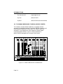
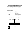
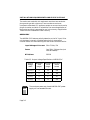
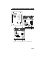
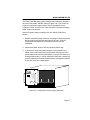
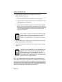
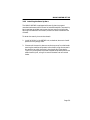
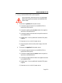
MMAC-M8FNB™
MULTI-MEDIA ACCESS CENTER
OVERVIEW AND SETUP GUIDE
CABLETRON SYSTEMS, P.O. Box 5005, Rochester, N.H. 03866-5005
NOTICE
Cabletron Systems reserves the right to make changes in
specifications and other information contained in this document
without prior notice. The reader should in all cases consult Cabletron
Systems to determine whether any such changes have been made.
The hardware, firmware, or software described in this manual is
subject to change without notice.
IN NO EVENT SHALL CABLETRON SYSTEMS BE LIABLE FOR
ANY INCIDENTAL, INDIRECT, SPECIAL, OR CONSEQUENTIAL
DAMAGES WHATSOEVER (INCLUDING BUT NOT LIMITED TO
LOST PROFITS) ARISING OUT OF OR RELATED TO THIS
MANUAL OR THE INFORMATION CONTAINED IN IT, EVEN IF
CABLETRON SYSTEMS HAS BEEN ADVISED OF, KNOWN, OR
SHOULD HAVE KNOWN, THE POSSIBILITY OF SUCH
DAMAGES.
© Copyright December 1995 by
Cabletron Systems, Inc.
P.O. Box 5005
Rochester, NH 03866-5005
All Rights Reserved
Printed in the United States of America
Order number: 9030535-08 December 1995
SPECTRUM, LANVIEW, and Multi Media Access Center are
registered trademarks and MMAC-M8FNB, MIM, M8PSM,
M8PSM-E, and M8PSM-EDC are trademarks of Cabletron Systems,
Inc.
Ethernet is a trademark of Xerox Corporation.
IBM is a registered trademark of International Business Machines
Corporation
i
FCC NOTICE
This device complies with Part 15 of the FCC rules. Operation is
subject to the following two conditions: (1) this device may not cause
harmful interference, and (2) this device must accept any interference
received, including interference that may cause undesired operation.
Note: This equipment has been tested and found to comply with the
limits for a Class A digital device, pursuant to Part 15 of the FCC
rules. These limits are designed to provide reasonable protection
against harmful interference when the equipment is operated in a
commercial environment. This equipment uses, generates, and can
radiate radio frequency energy and if not installed in accordance with
the operator’s manual, may cause harmful interference to radio
communications. Operation of this equipment in a residential area is
likely to cause interference, in which case the user will be required to
correct the interference at his own expense.
WARNING: Changes or modifications made to this device which are
not expressly approved by the party responsible for compliance could
void the user’s authority to operate the equipment.
DOC NOTICE
This digital apparatus does not exceed the Class A limits for radio
noise emissions from digital apparatus set out in the Radio
Interference Regulations of the Canadian Department of
Communications.
Le Présent appareil numérique n’émet pas de bruits radioélectriques
dépassant les limites applicables aux appareils numériques de la class
A prescrites dans le Règlement sur le brouillage radioélectrique édicté
par le ministère de Communications du Canada.
BABT NOTICE
This device is approved under BABT General Approval No.
NS/G/1234/J/100003 for indirect connection to public
telecommunications systems in the United Kingdom.
ii
VCCI NOTICE
This equipment is in the 1st Class Category (information equipment
to be used in commercial and/or industrial areas) and conforms to the
standards set by the Voluntary Control Council for Interference by
Information Technology Equipment (VCCI) aimed at preventing radio
interference in commercial and/or industrial areas.
Consequently, when used in a residential area or in an adjacent area
thereto, radio interference may be caused to radios and TV receivers,
etc.
Read the instructions for correct handling.
iii
iv
CONTENTS
CHAPTER 1
1.1
1.2
1.3
1.4
1.5
USING THIS MANUAL ............................................................ 1-1
1.1.1 Symbols.......................................................................... 1-2
USING THE MMAC-M8FNB MANUAL SET.......................... 1-2
GETTING HELP........................................................................ 1-3
THE MMAC-M8FNB MULTI MEDIA ACCESS CENTER ..... 1-4
MMAC-M8FNB FEATURES..................................................... 1-5
CHAPTER 2
2.1
2.2
2.3
2.4
2.5
INSTALLATION REQUIREMENTS AND
SPECIFICATIONS
SITE GUIDELINES................................................................... 2-1
MMAC-M8FNB CONFIGURATION GUIDELINES ............... 2-2
OPERATING SPECIFICATIONS............................................. 2-3
2.3.1 Physical Specifications.................................................. 2-3
2.3.2 Power Supply Requirements ........................................ 2-4
2.3.3 Test Points..................................................................... 2-7
LEDs ........................................................................................... 2-8
SAFETY.................................................................................... 2-12
CHAPTER 3
3.1
3.2
INTRODUCTION
MMAC-M8FNB SETUP
UNPACKING THE MMAC-M8FNB......................................... 3-1
SETTING UP THE MMAC-M8FNB ......................................... 3-2
3.2.1 Rack Mounting the MMAC-M8FNB Chassis .............. 3-2
3.2.2 Rack Mounting the Cable Tie Tray.............................. 3-4
3.2.3 Inserting the Fan Tray ................................................. 3-5
3.2.4 Installing the Power Supply Module............................ 3-6
3.2.5 Installing the Security Bars ......................................... 3-9
3.2.6 Powering Up the MMAC-M8FNB .............................. 3-10
v
CONTENTS
vi
CHAPTER 1
INTRODUCTION
The MMAC-M8FNB™ Multi Media Access Center offers
maximum flexibility and convenience in the design and operation of
your network. The enclosure provides space for one
Repeater/Management Module and up to seven Media Interface
Modules (MIM™), allowing up to 171 network connections depending
on the Repeater/Management module and the MIMs that have been
installed.
This manual is an installation and reference guide. It lists the
features and options of the MMAC-M8FNB and explains how to
install the fan tray and power supply(ies). You should read through
this manual prior to using the MMAC-M8FNB to gain a full
understanding of the MMAC-M8FNB and its capabilities.
Only qualified personnel should install or service this
unit and its modules!
1.1
USING THIS MANUAL
Chapter 1, Introduction, discusses the features and capabilities of
the MMAC-M8FNB.
Chapter 2, Installation Requirements and Specifications, lists
the location requirements that must be met before you install the
MMAC-M8FNB on your network. This chapter also includes some
MIM configuration guidelines, environmental guidelines, and
operating specifications for the MMAC-M8FNB and related Power
Supply Modules (M8PSM™, M8PSM-E™, or M8PSM-EDC™).
Page 1-1
INTRODUCTION
Chapter 3, MMAC-M8FNB Setup, contains instructions for rack
mounting your MMAC-M8FNB, inserting the fan tray, installing the
power supply(ies), installing the security bars, and powering up the
MMAC-M8FNB.
1.1.1
Symbols
Throughout this manual you will see two symbols which will be used
to call your attention to important safety-related information:
CAUTION: when you see this symbol, you will be
provided with special precautionary information that
can help you guard against improper use of your
equipment.
WARNING: when you see this symbol, note that failure
to follow the instructions provided can result in an
electrical safety hazard.
You will also see a third symbol, which will be used to call your
attention to additional information not related to safety:
NOTE
1.2
NOTE: the information that follows could help you to
better use and understand your equipment.
USING THE MMAC-M8FNB MANUAL SET
Other manuals have been developed for the Repeater/Management
modules and for each MIM that can be installed in your
MMAC-M8FNB. These manuals explain how to install the individual
Page 1-2
INTRODUCTION
modules into the MMAC-M8FNB, how to attach cable segments to the
modules, and how to test those segments after they have been
installed. Specifications for all modules are included in each manual.
Additional manuals have been developed on how to use Cabletron
Systems’ Network Management software packages; these manuals
include information about how to remotely manage the
MMAC-M8FNB and the M8PSM-E and M8PSM-EDC power supply
modules.
Each manual in this set assumes that you have a general working
knowledge of Ethernet or IEEE 802.3, 802.5, and FDDI type data
communications networks and their physical layer components.
1.3
GETTING HELP
If you need additional support related to the MMAC-M8FNB, or if you
have any questions, comments, or suggestions related to this manual,
contact Cabletron Systems Technical Support. Before calling, please
have the following information ready:
•
The product type (MMAC-M8FNB), and the product serial
number. The serial number is located on the front panel of the
MMAC, and the product type is on the fan tray label. Also, be
sure to note which power supply module or modules you have
installed: the M8PSM, the M8PSM-E, and/or the
M8PSM-EDC.
You can contact Cabletron Systems’ Technical Support Department by
any of the following methods:
By phone:
Monday through Friday between
8 A.M. and 8 P.M. Eastern
Standard Time at (603) 332-9400.
By Mail:
Cabletron Systems, Inc.
PO Box 5005
Rochester, NH 03866-5005
By CompuServe®:
GO CTRON from any ! prompt
Page 1-3
INTRODUCTION
1.4
By Internet mail:
[email protected]
By FAX:
(603) 337-3075
By BBS:
(603) 335-3358 (4 lines available)
THE MMAC-M8FNB MULTI MEDIA ACCESS CENTER
The Cabletron Systems MMAC-M8FNB is a complete modular
approach to integrated networks. The MMAC-M8FNB supports Local
Area Networks compliant to IEEE 802.3, IEEE 802.5, and FDDI
standards. It also supports all of the Cabletron Systems Media
Interface Modules (MIMs). Figure 1-1 below illustrates an
MMAC-M8FNB equipped with a variety of MIM cards.
TRMIM-22A TRMIM-22A TRMIM-4A
SN
SN
16MB
LNK
PEN
ERR
MGMT
16MB
LNK
PEN
1
X
2
X
3
X
4
X
5
X
6
X
1
X
2
X
3
X
4
X
5
X
6
X
1
X
2
X
3
X
4
X
5
X
6
X
7
X
8
X
9
X
10
X
11
X
12
X
7
X
8
X
9
X
10
X
11
X
12
X
7
X
8
X
9
X
10
X
11
X
12
X
ACTIVE UTP
TOKEN RING
EFDMIM
SN
LNK
PEN
ERR
MGMT
ACTIVE UTP
TOKEN RING
STAND
BY
POWER
MGMT
16MB
RI RO
CRS16
WFLT
WRAP
FO
FLNK
SYS
OK
SN
ETHERNET
TX
RX
COL
POK
4
3
2
1
B
Y
P
A
S
S
15
16
17
18
19
20
21
22
23
24
25
26
CLN
CLN
2
3
4
5
6
7
8
9
10
11
12
13
R L
C N
V K
R L
C N
V K
ERR
STBYA
STBYC
STBYB
STBYD
RCVA
RCVB
RCVC
RCVD
ON
CLNA
CLNB
CLNC
CLND
PWR
A
U
I
R L
C N
V K
1
TX
I
N
RX
14
1
14
1
14
1
F
D
D
I
ON
PWR
A
U
I
A
2
R
I
N
G
TX
O
U
T
13
26
13
26
13
M
O
D
E
M
C
O
N
S
O
L
E
F
D
D
I
B
RX
ACTIVE UTP
TOKEN RING
26
LINK
15
FDDI
2
10BASE-T
ETHERNET
15
2
10BASE-T
ETHERNET
15
2
10BASE-T
ETHERNET
MMAC-M8FNB
Multi Media Access Center
The Complete Networking Solution™
Figure 1-1. MMAC-M8FNB with Installed MIMs
Page 1-4
BOK
CLN
AUI POK
15
16
17
18
19
20
21
22
23
24
25
26
2
3
4
5
6
7
8
9
10
11
12
13
R L
C N
V K
R L
C N
V K
RESET
B C
CLN
AUI POK
15
16
17
18
19
20
21
22
23
24
25
26
2
3
4
5
6
7
8
9
10
11
12
13
R L
C N
V K
SN
ETHERNET
B C
CLN
AUI POK
F M
D M
D A
I C
ON NET
SN
ETHERNET
B C
CLN
TX
RX
WRAP
TOKISD
R
I
N
G
TPRMIM-36 TPRMIM-36 TPRMIM-36 EMME
SN
SN
ERR
C
O
N
S
O
L
E
ETHERNET
INTRODUCTION
A variety of IEEE 802.3, IEEE 802.5, and FDDI compliant media can
be connected to the MMAC-M8FNB, including shielded and
unshielded twisted pair, fiber optic cable, thick or thin coaxial cable,
and standard AUI transceiver cable. Each media type has a MIM
which, when installed into the MMAC-M8FNB, is compatible with all
other MIMs installed in that unit. The MMAC-M8FNB provides
complete network integration of a variety of media through a single
source.
The MMAC-M8FNB is designed so that network expansions or
changes in media types can be done without bringing down the entire
network — in a matter of minutes, you can add, change, or replace
MIMs without turning off the MMAC-M8FNB or using any special
tools. This design also allows the MMAC-M8FNB to continue to adapt
to ever-changing industry standards.
1.5
MMAC-M8FNB FEATURES
Three Power Supply Modules to Choose From
The MMAC-M8FNB chassis supports three different power supply
modules: the original M8PSM, the M8PSM-E enhanced model, and
the new M8PSM-EDC, an enhanced model that accepts DC power
input. In addition to all of the features of the M8PSM, the M8PSM-E
and -EDC enhancements include higher power output (450 watts — a
50% increase over the standard 300 watts), internal cooling (two fans
are located within the module itself), power factor correction
(M8PSM-E only), and remote management.
Auto-Ranging Power Supply
The M8PSM and M8PSM-E sense and automatically adjust to the
input voltage and frequency. No additional adjustments are necessary.
Built-in Power Supply Protection
The M8PSM, M8PSM-E, and M8PSM-EDC power supply modules
automatically power down under any of the following conditions:
thermal overload (thermal protection); shorted output (over current or
Page 1-5
INTRODUCTION
short circuit protection); or excess output voltage (over voltage
protection). The power supply will automatically recover when a
thermal overload condition is corrected; when an over current or over
voltage condition is corrected, the power supply requires power cycling
(turn power switch off, then on again) to recover. A FAULT LED on the
power supply modules indicates when an over current condition has
occurred.
Power Factor Correction
The M8PSM-E meets the EN60555-2 limits for power factor
correction, which may be required by utility companies in the near
future.
The power factor correction feature provides a number of advantages.
By improving this factor to meet the EN60555-2 limits, line noise and
peak current levels are dramatically reduced and the amount of power
available to the user is increased. Power factor correction also reduces
stress on fuses, circuit breakers, wall sockets, wiring, and
transformers.
Power OK Signal
On the M8PSM, the same signal that illuminates the Power OK LED
on the power supply module will also alert the management module
that the power supply is functioning normally. The M8PSM-E and
-EDC have both red and green power LEDs; power supply status as
indicated by the LEDs will also be sent to the management module.
Redundant Power with Load Sharing
Depending on the power requirements of the installed MIMs, the
MMAC-M8FNB can operate with either one or two power supply
modules. If two power supplies are installed, they share the power
load requirements of the installed MIMs; if one power supply fails, the
second automatically assumes the entire load if it is able. This ensures
that your network will remain operational until a replacement power
supply module can be installed.
Page 1-6
INTRODUCTION
Any two matching power supply modules (i.e., two M8PSMs, two
M8PSM-Es, or two M8PSM-EDCs) will use a current sharing scheme
such that each power supply provides 50% of the required load (±5%,
5V output only) under all load conditions; if you have one M8PSM and
one M8PSM-E installed, the M8PSM-E will supply 60% of the
required power, and the M8PSM will supply the remaining 40%.
Note that, if you have an M8PSM and an M8PSM-E installed in the
same chassis, the redundancy LED on the M8PSM-E will not function.
Note, too, that you cannot mix AC (M8PSM or M8PSM-E) and DC
(M8PSM-EDC) power supplies in the same hub.
NOTE
The power requirements of some FDDI MIM
configurations require dual power supplies. Consult the
appropriate manuals for details.
Hot Swapping
You have the option to “hot swap” power supply modules in the
M8FNB. This allows you to remove or insert power supplies without
powering down the M8FNB.
Internal Power Supply Cooling
The M8PSM-E and -EDC enhanced power supplies have two fans built
directly into the unit to provide additional cooling; red and green FAN
LEDs on the power supply’s front panel indicate whether all fans are
operational (green) or one or more has failed (red).
Power Level Indicator
The M8PSM-E and -EDC also include an 11-segment LED to indicate
the level of power currently being used by the chassis. Each
illuminated segment represents 10% of the maximum output; the
eleventh segment, when lit, indicates an overload condition. Note that,
if any one power supply is providing more than 50% of its available
power, there is no power supply redundancy available in the chassis.
Page 1-7
INTRODUCTION
NOTE
In a system in which two power supplies are installed
and each is using more than 50% power, LED segments
5-9 will illuminate yellow, warning of the loss of
redundancy.
Remote Management
The remote management capability built in to the M8PSM-E and
-EDC allows the network manager to determine whether or not an
installed power supply is an E-series model and whether or not power
supply redundancy is available; the M8PSM-Es and -EDCs can also be
remotely disabled if an emergency shutdown is required.
Power supply redundancy is available when two power supplies are
installed in your hub and when neither one is supplying more than
50% of its available power; this applies even when one M8PSM and
one M8PSM-E are combined in the same hub. (You cannot mix AC
[M8PSM or M8PSM-E] and DC [M8PSM-EDC] power supplies in the
same hub.)
NOTE
Page 1-8
For access to remote management features, your
MMAC-M8FNB must have the correct backplane
version (chassis revisions EL and above) and you must
have a Cabletron management module which supports
the M8PSM-E and -EDC. Note also that, although the
redundancy feature will function as described above,
the redundancy LEDs will not illuminate unless you
have two E-series power supplies installed and your
hub has the correct backplane. Contact Cabletron
Systems Technical Support for more information.
INTRODUCTION
Removable Fan Tray
The MMAC-M8FNB is equipped with a removable fan tray, which
means that you can replace a failed fan unit quickly, without any
special tools. The fan tray incorporates an LED that indicates fan
status; the same signal that illuminates the LED also alerts the
management module that the fans are operating properly.
The fan tray is hot-swappable; however, the MMAC
chassis should not be run for extended periods of time
without the fans installed, as it will quickly overheat.
Flexible Network Bus
The MMAC-M8FNB’s Flexible Network Bus allows the installed
power supplies to load share; it also allows Token Ring or FDDI
modules to communicate with one another, and to co-exist with
Ethernet modules in the same hub. Cabletron Systems offers a full
line of media interface modules that let you create new networks and
extend and connect existing networks.
Rack Mountable Chassis
The MMAC-M8FNB chassis can be mounted into a standard 19"
(48.26 cm) equipment rack. For safety and ease of network
connections, separate rack mount brackets are included that allow the
unit to be either flush mounted or recessed 3" from the front plane of
the rack mount unit.
Security Bars
A pair of security bars which fit over the knurled knobs that secure
the MIMs to the chassis protect the hub from unauthorized removal or
insertion of modules.
Page 1-9
INTRODUCTION
Page 1-10
CHAPTER 2
INSTALLATION REQUIREMENTS AND
SPECIFICATIONS
This chapter describes the following:
•
Site guidelines that must be met before installing an
MMAC-M8FNB onto your network
•
MMAC configuration guidelines
•
Operating specifications for the MMAC-M8FNB enclosure and
power supply module
Only qualified personnel should install or service this
unit and its modules.
2.1
SITE GUIDELINES
The following guidelines must be followed when you select a site for
the MMAC-M8FNB; if they are not, unsatisfactory network
performance may result.
•
An unrestricted free surface area of 53.3 cm (21 in.) wide,
62.2 cm (24.5 in.) deep and 44.5 cm (17.5 in.) high is
needed for the MMAC-M8FNB enclosure.
•
If the MMAC-M8FNB is to be placed on a shelving unit,
the shelf must be able to support 33.8 kg (75 lb.) of static
weight.
•
If the MMAC-M8FNB is to be rack-mounted, care must
be taken to ensure that the rack used will support the
unit and that the rack remains stable with the
MMAC-M8FNB installed. In order to allow proper
Page 2-1
INSTALLATION REQUIREMENTS AND SPECIFICATIONS
cooling within the rack, there must be 7.6 cm (3 in.) of
clearance above the unit and 5 cm (2 in.) of clearance on
either side of the unit.
2.2
•
For the M8PSM and M8PSM-E power supplies, a USA
standard 3 prong power receptacle must be located within
2.13 meters (7 feet) of the site. Each M8PSM-EDC power
supply requires a positive or negative DC power source at 36-72
volts which is capable of supplying 17 amps.
•
The temperature of the location must be maintained between
5° and 40°C (41° to 104°F). Temperature changes of greater
than 10°C (18°F) per hour must not occur.
MMAC-M8FNB CONFIGURATION GUIDELINES
The MMAC-M8FNB has eight slots that accept media interface
modules. The slots are numbered from right to left; slot #1 is a
half-width slot that is reserved for a management module. Cabletron
Systems management modules are equipped with a firmware-based
management tool called Local Management, which lets you control the
MMAC MIMs. Management modules are also SNMP compliant, which
means that an MMAC equipped with a management module can be
managed remotely by SNMP management software (such as any one
of Cabletron Systems’ SPECTRUM® for Open Systems suite of
management products.) The M8PSM-E and -EDC power supply
modules can also be managed remotely using appropriate
management software.
You can combine Token Ring, Ethernet, and FDDI MIMs in the same
MMAC; be sure to consult the appropriate management module and
MIM installation guides for detailed setup information.
Page 2-2
INSTALLATION REQUIREMENTS AND SPECIFICATIONS
2.3
OPERATING SPECIFICATIONS
The following lists the specifications for the MMAC-M8FNB enclosure
and for the M8PSM, M8PSM-E, and M8PSM-EDC power supplies.
Cabletron Systems reserves the right to change these specifications
without notice.
2.3.1
Physical Specifications
M8FNB
Dimensions:
14.5" high x 17" wide x 19" deep (36.8 cm high
x 43.2 cm wide x 48.3 cm deep)
Weight:
19 lb (8.6 kg) with fan tray
M8PSM
Dimensions:
9.6" high x 8.1" wide x 3" deep (24.4 cm high x
20.6 cm wide x 7.6 cm deep)
Weight:
5.75 lb (2.6 kg)
M8PSM-E
Dimensions:
9.6" high x 8.1" wide x 6" deep (24.4 cm high x
20.6 cm wide x 15.2 cm deep)
Weight:
8.5 lb (3.9 kg)
M8PSM-EDC
Dimensions:
9.6" high x 8.1" wide x 6" deep (24.4 cm high x
20.6 cm wide x 15.2 cm deep)
Weight:
8 lb (3.6 kg)
Page 2-3
INSTALLATION REQUIREMENTS AND SPECIFICATIONS
2.3.2
Power Supply Requirements
M8PSM
The M8PSM power supply senses and automatically adapts to the
input voltage and frequency.
Input Frequency:
50/60 Hz
Input Voltages & Current: 100 to 125 Vac, 5A
200 to 250 Vac, 2.5A
Fuses:
One 250 V, 10 Amp fuse (not
user serviceable)
BTUs/Hour:
1575.2
Table 2-1. Output Voltage Specifications: M8PSM
NOTE
Output
Voltage
(Vdc)
Minimum
Load
(amps)
Maximum
Load
(amps)
Maximum
Power
(watts)
+5 (±5%)
3
40
200
+12 (±5%)
0
5
60
-5 (±5%)
0
2
10
-9 (±5%)
0
11
99
The maximum power out of each M8PSM power supply
will not exceed 300 watts.
The mains cord used with this equipment must be a two-conductorplus-ground type with minimum 1 mm2 conductors and must
incorporate a standard IEC appliance coupler on one end and a mains
Page 2-4
INSTALLATION REQUIREMENTS AND SPECIFICATIONS
plug on the other end which is suitable for the use and application of
the product and that is approved for use in the country of application.
These units are intended for indoor use only.
M8PSM-E
The M8PSM-E power supply senses and automatically adapts to the
input voltage and frequency.
Input Frequency:
50/60 Hz
Input Voltages & Current: 100 to 125 Vac, 8A
200 to 250 Vac, 4A
Fuses:
One 250V, 12 Amp fuse (not
user serviceable)
BTUs/Hour:
2362.8
Table 2-2. Output Voltage Specifications: M8PSM-E
NOTE
Output
Voltage
(Vdc)
Minimum
Load
(amps)
Maximum
Load
(amps)
Maximum
Power
(watts)
+5 (±5%)
3
60
300
+12 (±5%)
0
10
120
-5 (±5%)
0
2
10
-9 (±5%)
0
15
135
The maximum power out of each M8PSM-E power
supply will not exceed 450 watts.
Page 2-5
INSTALLATION REQUIREMENTS AND SPECIFICATIONS
The mains cord used with this equipment must be a two-conductorplus-ground type with minimum 1 mm2 conductors and must
incorporate a standard IEC appliance coupler on one end and a mains
plug on the other end which is suitable for the use and application of
the product and that is approved for use in the country of application.
These units are intended for indoor use only.
M8PSM-EDC
The M8PSM-EDC features polarity detection on the DC input; if the
unit has been incorrectly installed and polarity is reversed, an
internal buzzer will sound alerting the user to take corrective action.
Input Voltages & Current: 36 to 72 Vdc, 17A
Fuses:
One 250 V, 20 Amp fuse (not
user serviceable)
BTUs/Hour:
2362.8
Table 2-3. Output Voltage Specifications: M8PSM-EDC
NOTE
Page 2-6
Output
Voltage
(Vdc)
Minimum
Load
(amps)
Maximum
Load
(amps)
Maximum
Power
(watts)
+5 (±5%)
3
60
300
+12 (±5%)
0
10
120
-5 (±5%)
0
2
10
-9 (±5%)
0
15
135
The maximum power out of each M8PSM-EDC power
supply will not exceed 450 watts.
INSTALLATION REQUIREMENTS AND SPECIFICATIONS
These units are intended for indoor use only, and must be used with a
user-supplied two-conductor-plus-ground cable with minimum 3 mm2
diameter conductors and terminated with #6 ring terminals. Cable
must contain minimum 10 AWG wire.
To reduce the risk of electric shock or energy hazards,
install the M8PSM-EDC according to the following
guidelines:
1. Connect to a positive or negative 48Vdc SELV
source which is reliably connected to earth ground.
2. The branch circuit overcurrent protection must be
rated 20A.
3. Use 10 AWG solid copper conductors only.
4. Disconnect both input supply sources before
servicing.
5. A readily accessible disconnect device that is
suitably approved and rated, shall be incorporated
in the field wiring.
6. MMAC-M8FNB is to be installed in a restricted
access area in accordance with the national electric
code or the authority having jurisdiction.
2.3.3
Test Points
Each power supply module has service-accessible test points for
measuring each output, as well as for testing the power fail indication
signal (see Tables 2-1, 2-2, and 2-3, above). Test points can measure
each individual unit even when it is installed in parallel with another
unit.
Page 2-7
INSTALLATION REQUIREMENTS AND SPECIFICATIONS
NOTE
The power supply test points represent the power supply
output voltages and not the bus voltage seen by the
Media Interface Modules. The voltages measured at the
test points are one diode voltage drop above the bus
voltage. The following are the voltage tolerances which
ensure that the bus voltage is within specified limits:
+5 V test
+12 V test
-5 V test
-9 V test
5.10 V to 5.75 V
11.75 V to 13.10 V
-5.10 V to -5.75 V
-8.90 V to -10.05 V
Power Fail Indication:
2.4
Power good
<1 V
Power bad
>4 V
LEDs
Power OK
(Power Supply)
When lit, this green LED indicates that the
power supply module is operating correctly; a
signal is also sent to the management/repeater
module to indicate that the power supply is
functioning properly.
Power Fail
(Power Supply)
When lit, this red LED indicates a loss of input
power, loss of regulation on any output, or the
activation of any power fail circuit protection.
NOTE
Page 2-8
On the M8PSM-E and -EDC, the above-described
Power OK and Power Fail LEDs are simply labeled
“Power.” When the green LED is illuminated, the power
supply is operating correctly, as described in Power
OK, above; the red LED indicates the same trouble
conditions described in Power Fail, above.
INSTALLATION REQUIREMENTS AND SPECIFICATIONS
POWER
OK
FAIL
M8PSM
+5 VOLT TEST
-5 VOLT TEST
SN
+12 VOLT TEST
-9 VOLT TEST
COMMON
POWER FAIL INDICATION
POWER LEVEL
FAULT
POWER
REDUNDANCY
OL
100%
FAN
DISABLE
50%
100 - 125 ~ 8A
200 - 250 ~ 5A
50/60 Hz
10%
SN
POWER LEVEL
100 - 125 ~ 8A
200 - 250 ~ 5A
50/60 Hz
FAULT
POWER
REDUNDANCY
OL
100%
FAN
DISABLE
50%
10%
SN
FAULT
Figure 2-1. The M8PSM, M8PSM-E, and M8PSM-EDC
Page 2-9
INSTALLATION REQUIREMENTS AND SPECIFICATIONS
Power Fail
(Power Supply)
NOTE
When lit, this red LED indicates a loss of input
power, loss of regulation on any output, or the
activation of any power fail circuit protection.
On the M8PSM-E and -EDC, the above-described
Power OK and Power Fail LEDs are simply labeled
“Power.” When the green LED is illuminated, the power
supply is operating correctly, as described in Power
OK, above; the red LED indicates the same trouble
conditions described in Power Fail, above.
Fault
(Power Supply)
When lit, this red LED indicates that an over
current (short circuit) condition has occurred;
this condition could result from inadequate
power to the hub (only one power supply
installed where two are required), or from a
problem in the chassis itself. Once the over
current condition has been corrected, the power
supply requires power cycling (turn the power
switch off for at least ten seconds, then on
again) to recover.
Redundancy
(E-series only)
A green LED indicates that two E-series power
supplies are installed in a chassis with the
correct backplane (chassis revisions EL and
above) and that redundancy is available
(neither power supply operating at more than
50% output); a red LED indicates that two
E-series power supplies are installed in a
chassis with the correct backplane and the
redundancy is not available (each power
supply operating at greater than 50% output).
If neither LED is lit, an M8PSM-E has been
installed in the same chassis as an M8PSM, or
the chassis has an older backplane and must be
upgraded to fully use the E-series features.
Page 2-10
INSTALLATION REQUIREMENTS AND SPECIFICATIONS
NOTE
Even if neither LED is lit, redundancy is still available
if neither power supply is operating at more than 50%
output. This is true even when one M8PSM and one
M8PSM-E are installed in the same chassis.
Fan
(E-series only)
A green LED indicates that all fans inside the
M8PSM-E or -EDC module are operating
properly; a red LED indicates that one or more
has failed.
Disable
(E-series only)
If this red LED is illuminated, the power
supply has been disabled remotely.
Power Level
(E-series only)
When illuminated, each of the first ten
segments of this LED indicates that 10% of
total power output is being used; the eleventh
segment, when illuminated, indicates a power
overload. Note that, in a redundant system,
segments 5-9 will illuminate yellow to warn of
loss of redundancy.
Fan Tray LED
(Chassis)
This LED is green when all the fans are
operating properly; it turns red when any fan
slows to half speed or less, and signals the
management/repeater module that there is a
fan tray problem. Note that this LED will also
turn red when the fan tray board’s logic has
failed due to a blown fuse; in this case, all fans
may still be operating.
NOTE
When the M8FNB is first powered up, this LED will be
red briefly until the fans are operating at the proper
speed. Also, don’t confuse this fan tray LED (located on
the front of the fan tray installed at the bottom of the
chassis) with the Fan LED on the front panel of the
M8PSM-E and -EDC. This fan tray LED indicates the
operating status of the fans in the MMAC chassis; the
Fan LED on the M8PSM-E and -EDC indicates the
status of the fans inside the power supply itself.
Page 2-11
INSTALLATION REQUIREMENTS AND SPECIFICATIONS
2.5
SAFETY
Designed in accordance with UL1950, CSA C22.2 No. 950, IEC950,
and EN 60950. Meets the EMI requirements of FCC Part 15 Class A,
VCCI Class I, and EN 55022 Class A. Meets the immunity
requirements of EN 50082-1.
In addition, the MMAC-M8FNB chassis and the M8PSM-E and
M8PSM-EDC power supplies have been tested by Bellcore and found
to comply with the following standards:
•
TR-NWT-000063 Network Equipment Building System (NEBS)
Generic Equipment Requirements
•
GR-1089-CORE EMC and Electrical Safety Generic Criteria for
Network Telecommunications Equipment
This unit must be assembled and used in accordance
with the instructions in this manual.
NOTE
Page 2-12
It is the responsibility of the person who sells the system
of which the MMAC-M8FNB will be a part to ensure
that the total system meets allowed limits of conducted
and radiated emissions.
CHAPTER 3
MMAC-M8FNB SETUP
This chapter contains instructions to help you set up Cabletron
Systems’ MMAC-M8FNB. You will not need any special tools or
equipment to set up the MMAC-M8FNB, but you must follow all
guidelines listed in Chapter 2, Installation Requirements and
Specifications.
Only qualified personnel should install or service this
unit and its modules.
3.1
UNPACKING THE MMAC-M8FNB
Before you install the MMAC-M8FNB, you should inspect the unit.
To unpack the MMAC-M8FNB:
1. Remove the MMAC-M8FNB and fan tray from the shipping box.
Save the shipping box and materials in the event the
MMAC-M8FNB has to be reshipped.
2. Slide the two foam end caps off the MMAC-M8FNB, and remove
the unit from the protective plastic bag. Set the MMAC-M8FNB
aside in a safe place.
3. Remove the accessory package and verify that it contains two
mounting brackets, a cable tie tray, and two security bars.
Contact Cabletron Systems Technical Support immediately if any
discrepancy exists.
Page 3-1
MMAC-M8FNB SETUP
3.2
SETTING UP THE MMAC-M8FNB
The following sections list the steps necessary to set up your
MMAC-M8FNB, including installing the MMAC-M8FNB in the
desired location, inserting the fan tray, inserting the power supply
module(s), and installing the security bars.
3.2.1
Rack Mounting the MMAC-M8FNB Chassis
To mount the MMAC-M8FNB in a standard 19" equipment rack:
1. Using a Phillips head screwdriver, remove the eight screws (item 1,
Figure 3-1) – four on each side of the MMAC-M8FNB – which are
closest to the front of the chassis, and set them aside.
2. The rack mount brackets (item 2) provided have two sets of holes:
use the front holes (item 3) to mount the chassis flush with the
equipment rack; use the rear holes (item 4) to mount the chassis
so that it is recessed 3" from the front of the rack. Align the
appropriate four holes on one rack mount bracket with the four
holes from which you removed the screws.
3. Insert the screws through the holes on the mounting bracket and
into the screw holes on the MMAC-M8FNB.
4. Tighten the screws until the mounting bracket is securely attached
to the unit.
5. Repeat steps 2-4 for the second rack mount bracket. Be sure to use
the same set of holes on the second rack mount bracket (front for
flush mount, rear for recessed mount) that you used on the first
bracket.
6. Slide the unit into the rack, being sure to leave sufficient room to
install the cable tie tray, if desired.
Page 3-2
MMAC-M8FNB SETUP
MMAC-M8FNB
Multi Media Access Center
The Complete Networking Solution™
1
4
2
5
1.
2.
3.
4.
5.
6.
3
6
Screws (8 total; 4 each side)
Rack mount bracket
Holes for flush mount
Holes for recessed mount
Bolts (secure with locking washers)
Equipment Rack
Figure 3-1. Installing the M8FNB into a Rack
7. Align the slots on each mounting bracket with the desired holes on
the equipment rack.
8. Insert a bolt (item 5) through the slot in each of the mounting
brackets and into the threaded holes in the equipment rack (item
6). Secure bolts with locking washers.
9. Tighten the nuts and bolts until the unit is secured to the rack.
Page 3-3
MMAC-M8FNB SETUP
3.2.2
Rack Mounting the Cable Tie Tray
A cable tie tray is provided with the MMAC-M8FNB to support and
organize cables connected to the unit. The tray is designed to be
installed under the MMAC-M8FNB in the equipment rack. To mount
the cable tray in a standard 19" equipment rack:
1. Slide the cable tie tray (Figure 3-2) into the rack.
2. Align the slots on each mounting bracket on the tray with the
desired holes on the equipment rack.
3. Insert a bolt through the slots in each of the mounting brackets and
into the threaded holes in the equipment rack. Use nuts with
locking washers to secure the bolts.
4. Tighten the nuts and bolts until the tray is secured to the rack.
MMAC-M8FNB
Multi Media Access Center
The Complete Networking Solution™
Figure 3-2. Cable Tie Tray Installation
Page 3-4
MMAC-M8FNB SETUP
3.2.3
Inserting the Fan Tray
The MMAC-M8FNB is equipped with a removable fan tray that allows
for easy periodic cleaning and/or replacement if a problem occurs with
fan operation. To insert the fan tray in the MMAC-M8FNB:
1. Hold the fan tray as shown in Figure 3-3 (following page) and align
the slotted paths on the tray with the slot guides on the left and
right walls of the MMAC-M8FNB chassis.
2. Slide the fan tray forward until the tray’s face is flush with the face
of the MMAC-M8FNB. If you encounter any strong resistance,
remove the fan tray and reinsert it. Do not force the fan tray into
place as this may damage the unit.
3. Once the tray is in place, tighten the knurled knobs to secure the
tray to the MMAC-M8FNB.
4. When the MMAC-M8FNB is ready to be turned on, observe the
LED on the front of the fan tray. This LED should be red for a
moment after you turn on the power switch, and then change to
green to indicate that all the fans are operating properly.
If this LED remains red, it indicates that one or more of the fans is
not operating at the proper speed. Check the fan tray to ensure that
nothing is interfering with movement of the fans; also, check to
make sure nothing is blocking the air vents on the chassis or the
fan tray. If you cannot find the problem, call Cabletron Systems
Technical Support for assistance.
The fan tray is hot-swappable; however, the chassis
must not be run without the fan tray for extended
periods of time, as it will quickly overheat.
Page 3-5
MMAC-M8FNB SETUP
MMAC-M8FNB
Multi Media Access Center
The Complete Networking Solution™
Slot guide
Knurled knob
Fan tray LED
Figure 3-3. Inserting the Fan Tray
3.2.4
Installing the Power Supply Module
You must install at least one power supply module in your
MMAC-M8FNB. One MMAC-M8PSM provides sufficient power for
many MIM configurations, but you may choose to install the more
powerful M8PSM-E for some MIM configurations, or the M8PSM-EDC
for use with a DC power source; with any model, you can also install a
second power supply as a redundant and/or load-sharing power
source. (Note that the power requirements of some FDDI
configurations require dual power supplies.) When two power supply
modules are installed, the load is evenly distributed; if one power
supply fails for any reason other than a shorted DC backplane, the
second power supply assumes the load, if it can, even when one
M8PSM and one M8PSM-E are installed in the same chassis.
An M8PSM-EDC power supply cannot be installed in
the same chassis as an M8PSM or M8PSM-E.
Page 3-6
MMAC-M8FNB SETUP
The MMAC-M8FNB power supply modules are installed in the slots in
the rear of the MMAC-M8FNB chassis (Figure 3-4). If you intend to
install a single power supply module, the single module can be
installed in either the left or the right slot; be sure to leave the empty
power supply slot covered.
Install the power supply module(s) into your MMAC-M8FNB as
follows:
1. Unpack the power supply module by removing it from the shipping
box and sliding the two foam end caps off the unit. Save the
shipping box and materials in the event the unit must be
reshipped.
2. Remove the power supply from its protective plastic bag.
3. If you plan to install two power supplies, use a screwdriver to
loosen the knurled knobs securing the panel covering one of the
power supply slots, and remove the panel. If you plan to install only
a single power supply, it can be installed in either slot; remove the
panel if necessary to uncover the desired slot, and replace the panel
on the slot you plan to leave empty.
POWER
OK
FAIL
The Complete Networking Solution
M8PSM
+5 VOLT TEST
-5 VOLT TEST
SN
+12 VOLT TEST
-9 VOLT TEST
COMMON
POWER FAIL INDICATION
FAULT
100 - 125 ~ 8A
200 - 250 ~ 5A
50/60 Hz
115-230V~ 8A
8A
115-230V~
50/60 Hz
Hz
50/50
115-230V ~ 8A
50/60 Hz
Figure 3-4. Installing the Power Supply Module(s)
Page 3-7
MMAC-M8FNB SETUP
4. Slide the power supply into the appropriate slot of the
MMAC-M8FNB as follows:
a. Hold the module by the two handles on its front panel.
b. Align the power supply module with the slotted paths on the
top and bottom of the opening.
c.
Ensuring that the power supply is inserted into the slotted
paths, carefully slide the module forward until the module is
connected to the backplane. Do not force the module into place!
If you encounter significant resistance, remove the power
supply and reinsert it.
NOTE
When properly installed, the face of the M8PSM power
supply module will be flush with the rear panel of the
MMAC chassis; the face of the M8PSM-E or -EDC,
however, will extend about 3” out from the rear panel.
5. Use as screwdriver to tighten the knurled knobs and secure the
power supply module to the chassis.
6. If you are installing an additional power supply module, repeat
steps 3 - 5.
NOTE
One M8PSM and one M8PSM-E can be combined in a
single chassis, without loss of functionality; however,
the Redundancy LEDs on the M8PSM-E will not
operate. See Chapter 2 for more details. Note, too, that
you cannot install an M8PSM-EDC in the same chassis
as either of the AC power modules.
After you have finished installing the power supply module(s), the
MMAC-M8FNB is ready to be powered up; however, we recommend
that you first install the repeater/management module and the MIM
or MIMs, as well as the security bars. Refer to the applicable module
manuals for more information about MIM installation; see below for
security bar installation and power-up instructions.
Page 3-8
MMAC-M8FNB SETUP
3.2.5
Installing the Security Bars
The MMAC-M8FNB is equipped with security bars to prevent
unauthorized access to the hub and its installed modules. Two security
bars have been provided: one to cover the top row of knurled knobs
securing the modules to the chassis, and one to cover the bottom row
of knobs.
To attach the security bars to the chassis:
1. Install all MIMs in the M8FNB hub, as desired; be sure to install
panels over any empty slots.
2. Place one of the security bars across the top row of knurled knobs
securing the modules and panels to the chassis; align the screws in
the security bar with the holes in the chassis (as illustrated in
Figure 3-5), and tighten the screws. Repeat the procedure with the
second security bar, using it to cover the bottom row of knurled
knobs.
Page 3-9
MMAC-M8FNB SETUP
Install the security bars over the knurled
knobs on the modules; align the screws in
the security bars with the holes in the
chassis as indicated, and secure.
TRMIM-22A TRMIM-22A TRMIM-4A
SN
SN
16MB
LNK
PEN
ERR
MGMT
16MB
1
X
2
X
3
X
4
X
5
X
6
X
1
X
2
X
3
X
4
X
5
X
6
X
7
X
8
X
9
X
10
X
11
X
12
X
7
X
8
X
9
X
10
X
11
X
12
X
ACTIVE UTP
TOKEN RING
EFDMIM
SN
LNK
PEN
ERR
MGMT
ACTIVE UTP
TOKEN RING
LNK
PEN
1
X
2
X
3
X
4
X
5
X
6
X
7
X
8
X
9
X
10
X
11
X
12
X
STAND
BY
POWER
MGMT
16MB
RI RO
CRS16
WFLT
WRAP
FO
FLNK
SYS
OK
SN
ETHERNET
TX
RX
COL
POK
4
3
2
1
B
Y
P
A
S
S
15
16
17
18
19
20
21
22
23
24
25
26
CLN
CLN
BOK
CLN
AUI POK
15
16
17
18
19
20
21
22
23
24
25
26
2
3
4
5
6
7
8
9
10
11
12
13
R L
C N
V K
R L
C N
V K
RESET
B C
CLN
AUI POK
15
16
17
18
19
20
21
22
23
24
25
26
2
3
4
5
6
7
8
9
10
11
12
13
R L
C N
V K
SN
ETHERNET
B C
CLN
AUI POK
F M
D M
D A
I C
ON NET
SN
ETHERNET
B C
CLN
TX
RX
WRAP
TOKISD
R
I
N
G
TPRMIM-36 TPRMIM-36 TPRMIM-36 EMME
SN
SN
ERR
Chassis
holes
2
3
4
5
6
7
8
9
10
11
12
13
R L
C N
V K
R L
C N
V K
ERR
STBYA
STBYC
STBYB
STBYD
RCVA
RCVB
RCVC
RCVD
ON
CLNA
CLNB
CLNC
CLND
PWR
A
U
I
R L
C N
V K
1
TX
I
N
RX
14
1
14
1
14
1
ON
F
D
D
I
PWR
A
U
I
A
2
R
I
N
G
TX
O
U
T
13
26
13
26
13
M
O
D
E
M
C
O
N
S
O
L
E
F
D
D
I
B
RX
ACTIVE UTP
TOKEN RING
26
LINK
15
FDDI
2
10BASE-T
ETHERNET
15
2
10BASE-T
ETHERNET
15
C
O
N
S
O
L
E
2
10BASE-T
ETHERNET
ETHERNET
MMAC-M8FNB
Multi Media Access Center
The Complete Networking Solution™
Figure 3-5. Installing the Security Bars
3.2.6
Powering Up the MMAC-M8FNB
Power up the MMAC-M8FNB as follows:
1. If the MMAC-M8FNB will not be rack mounted, place it on the
selected site.
2. For any installed M8PSM or M8PSM-E power supplies:
a. Plug a power cord into the power receptacle located on the front
of each installed power supply.
b. Plug the power cord(s) into an outlet and move the power
switch on each power supply to the on position.
Page 3-10
MMAC-M8FNB SETUP
3. For any installed M8PSM-EDC power supplies:
Verify that the DC power source is off or disconnected
before making power connections to the M8PSM-EDC
power supply.
a. To connect to a positive 48 volt power source:
1.) Connect the ground terminal on the M8PSM-EDC to
appropriate earth ground.
2.) Connect the positive 48 volt return lead to the negative
terminal on the M8PSM-EDC.
3.) Connect the positive 48 volt lead to the positive terminal
on the M8PSM-EDC.
4.) Repeat steps 1-3 for any additional installed EDC power
supplies.
5.) Reconnect or turn on the DC power source.
6.) Move the power switch on each power supply to the ON
position.
b. To connect to a negative 48 volt power source:
1.) Connect the ground terminal on the M8PSM-EDC to
appropriate earth ground.
2.) Connect the negative 48 volt return lead to the positive
terminal on the M8PSM-EDC.
3.) Connect the negative 48 volt lead to the negative terminal
on the M8PSM-EDC.
4.) Repeat steps 1-3 for any additional installed EDC power
supplies.
5.) Reconnect or turn on the DC power source.
Page 3-11
MMAC-M8FNB SETUP
6.) Move the power switch on each power supply to the ON
position.
4. Make sure that the Power OK LED is lit.
NOTE
If you have not yet installed a repeater/management
module and/or a MIM or MIMs, the Fault LED may
illuminate when the power switch is turned on. If this
happens, turn the power supplies off, install the MIMs,
then turn the power supplies back on (remember, power
cycling is required once the Fault LED has been lit). At
that time, the green (Power OK) LED should
illuminate.
5. Make sure that all the fans in the chassis fan tray unit are
operating correctly when power is received from the power supply
modules (the fan tray LED will be green).
If you experience any problems during the installation of the
MMAC-M8FNB, contact Cabletron Systems Technical Support for
assistance.
Page 3-12