1
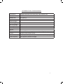
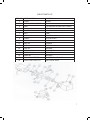
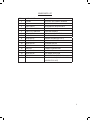
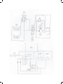
Stainless Steel Lift Table
Service Manual
LIFT PRODUCTS INC
PO BOX 349
ELM GROVE WI 53122
262-521-5720 FAX 262-521-5725
Toll Free 877-543-8776
Model: SXT-040-36 and SXT-045-36
S/N ________________________________
Customer____________________________
STANDARD WARRANTY
A.
Obligations of Seller: During the warranty period, Seller shall repair, or at Seller’s option, replace parts determined by Seller to be defective in material or workmanship. The
warranty period is (1) year from the date of delivery to Buyer F.O.B. point of
manufacturer. The foregoing shall be the sole obligation of Seller under this warrant
with respect to the equipment and other property included in this agreement. With
respect to equipment, materials, parts and accessories manufactured by others, Seller’s sole obligation shall be to use reasonable efforts to obtain for Buyer the full benefit of the manufacturer’s warranties and is limited to replacement of those components only. Warranty does not include labor or expenses for removal or replacement of those items.
B.
Warranty Exclusions: Repair or replacement of parts required because of misuse,
improper care or storage, negligence, alteration, accident, use of incompatible supplies or lack of specified maintenance are excluded from Seller’s warranty obligations.
C.
Seller shall not be held responsible for work done, material furnished, repairs or designs
made by others unless Seller so agrees in writing. Further, any such work done without
Seller’s consent or supervision immediately voids any warranties specified in this
proposal.
D.
In the event Purchaser believes it is entitled to make a warranty claim hereunder,
Purchaser shall notify Seller, and Purchaser and Seller shall mutually determine the
nature and extent of the claim and the location at which rework or replacement,
if any, shall be performed. Seller shall have no responsibility for costs incurred by
Purchaser in making preparations for rework or replacement.
E.
DISCLAIMER OF WARRANTIES: THE FOREGOING WARRANTY EXPRESSIONS ARE IN LIEU
OF ALL OTHER WARRANTIES, EXPRESSED OR IMPLIED, INCLUDING IMPLIED
WARRANTIES OF MERCHANTABILITY AND FITNESS FOR A PARTICULAR PURPOSE, AND EXISTENCE OF ANY SUCH OTHER WARRANTY IS HEREBY DENIED.
F. Limitations of liability and remedies: The liability of Seller for breach of any warranty
obligation hereunder is limited to: (I) the repair or replacement of the equipment on
which the liability is based; or (II) at Seller’s option, the refund to Buyer of the amount
paid by Buyer to Seller for said equipment. All other liability of Seller with respect to this
Agreement, or from the manufacture, installation, maintenance, repair or use of any
equipment covered by or furnished under this Agreement whether in contract or in
tort, or otherwise, is limited to the amount paid by Buyer to Seller pursuant to the terms
here on: SELLER SHALL NOT BE LIABLE FOR INCIDENTAL OR CONSEQUENTIAL DAMAGES
OF ANY KIND WHAT SO EVER. THE REMEDIES SET FORTH ARE EXCLUSIVE.
G.
Breach: Any breach by Seller with respect to any items or unit of equipment shall be
deemed a breach with respect to that item or unit only.
H.
Infringement: Seller will not be liable for the infringement of any patent by the Buyer’s use of
any equipment or materials delivered here under.
2
LIFT PRODUCTS SXT LIFT SPECIFICATIONS
Construction
Capacity
Platform Size
Base Size
Lowered Height
Raised Height
Toe Guard Height
Elevation Time
Decent Time
Leg Sets
Power Unit
Controls
Actuation
Code Compliance
Compete Fabrication from Heavy Duty T304 Stainless Steel
4,000 lbs
42” x 48” x 4”
35-1/2” x 45”
9”
36”
3”
@ 30 seconds
@ 24 seconds
1
110 Volt TEFC Motor integrally mounted providing 1 hp output
Up/Down hand pendant control
Dual, low pressure hydraulic cylinders, washdown, white epoxy-coated
USDA approved, OSHA encouraged
3
INTRODUCTION
Thank you for purchasing our Lift Products equipment! We know you will be delighted with the
Lift Products quality and performance. Please read this owner’s manual carefully before using
your stationary lift. Keep this manual in an accessible place for easy reference. If calling or
writing about your lift, please give the model number and serial numbers so that your order or
questions can be taken care of promptly.
INCREASED PRODUCTIVITY
This sanitary lift can be used to raise and lower products vertically. This could reduce loss time
injuries due to back strain and cumulative trauma illness. This reduction could increase job
efficiency, productivity and work quality.
SAFETY FIRST
WARRING!!! FAILURE TO FOLLOW THE INSTRUCTIONS IN THIS MANUAL CAN CAUSE PERSONAL
INJURY AND/OR PROPERTY DAMAGE.
Carefully read all safety signs and labels in good condition and replace those that are damaged.
WARNING!!! WATCH HANDS AND FINGERS! KEEP ALL EXTREMITIES AWAY FROM SCISSORS
ARMS WHEN LIFT IS IN OPERATION!
Lift Products Safety Features:
• Continouous-touch start/stop hand pendant buttons
LOCK OUT PROCEDURES
When cleaning, maintaining or disassembly is required, the lift should be completely powerless.
The main power to the lift controls and power unit must be disconnected and locked out.
SET UP
1. After locating the unit in the work area, anchor the base firmly to a level floor before
operating.
A. When leveling the unit, shims may be used to obtain a level position. Lift Products
recommends using a grout to provide a solid surface underneath the support angle
base. The channel must have a solid base to support the wheels or damage/failure to the support could result.
4
B. There are 4 anchor points on the lift. These are located on the outside perimeter of the lift. Use a corrosion resistant 3/4” bolt in ALL 4 points for proper anchorment.
C. To access the four inside anchor points, the lift must be raised. See the electrical
diagram for proper wiring.
2. Plug the power cable into a 100 AC, properly grounded outlet with sufficient amperage capacity to run a 1 HP electric motor.
3. Check hydraulic fluid level in the reservoir. The level should be 1-1/2” below the fill hole.
4. Check each if the 6 grease points on the lift. They are located on the four wheel areas and the
middle of the scissor arms. These are usually greased from our factory.
5. The 6 grease points should be greased on a regular basis. Depending on your type of operation and wash down procedures. Lift Products recommends you grease these points on a weekly
basis.
OPERATION
WARNING!!! KEEP ALL EXTREMITIES AWAY FROM ALL MOVING PARTS, UNDER NO CIRCUMSTANCES SHOULD ANY ONE WALK UNDER OR HAVE ANY PART OF THEIR BODY UNDER THIS
LIFT.
NOTE: LOADS MUST NOT EXCEED 4000LBS. FOR THIS LIFT (SXT) MODEL
Once the unit has been properly set up per the SET UP instructions, try the unit empty first to
test the operation to be sure it is working properly. Then test the unit with a load. Keep all loads
properly centered and balanced as much as possible.
CAUTION: AWKWARD PLACEMENT OF LOAD COULD CAUSE EQUIPMENT DAMAGE!
Engage the foot petal to raise or lower the lift. The foot pedal is a momentary control which
allows easy operation. The unit can be started or stopped at any position throughout the units
cycle.
CAUTION: WHEN LIFTING HEAVY LOADS, DO NOT JOG THE UNIT MORE THAT 2-3 TIMES TOO
QUICKLY. WAIT APPROX. 5 SECS. BETWEEN EACH JOG. SUDDEN JOGS MAY CAUSE THE UNIT TO
HAVE SURGES IN ELECTRICAL POWER. THIS COULD CAUSE THE FUSE TO TRIP EXCESSIVELY AND
CAUSE IMPROPER WEAR ON THE HYDRAULIC UNIT.
To lower a product or to lower the top down itself, depress, the DOWN pedal and the unit will
lower. This done without the power unit engaging.
REMEMBER---SAFETY FIRST!!!--- IF YOU HAVE ANY PROBLEMS WITH YOUR LIFT, CONSULT THE
FOLLOWING PAGE FOR “PROBLEMS/SOLUTIONS”.
5
Problem Situation
• Motor to power unit does not turn on
• Motor turns on but will not lift product
• Motor and pump do not run smoothly
• Non-level platform while raising load
• Excessive oil about base of hydraulic
cylinders
Suggested Solution
• Check electrical service
• Check and/or replace fuse
• Loose wires in juction box
• Check and/or replace motor
• Hydraulic fluid is low and needs to be
filled
• Pump coupling between motor and
hydraulic pump has come loose or needs
to be replaced
• Check and/or replace hydraulic pump
• Strainer has become plugged and needs to
be cleaned
• Air in the hydraulic lines needs to be
removed
• Dirt or foreign particles in hydraulic fluid
• Motor has come loose from base plate
and needs tightening
• Check and/or replace hydraulic pump
• Check and/or replace motor
• Air in the hydraulic cylinders needs to be
removed
• Check and/or replace roller chain and
sprocket
• Flow divider is plugged
• Hydraulic fitting to cylinder is loose and
needs to be tightened
• Check and/or replace hydraulic hose
• O-rings in hydraulic cylinders need to be
replace
6
SERVICE PARTS LIST
ITEM NO.
2
3
4
5
6
7
8
9
10
11
12
13
14
15
16
17
18
PARTS NUMBER
113583
1487AA, 1485AA, 2361AB
KM97
KN12
GI-1073-48
KP12
K-40
2130AC
T2 5001-00
1611-AA
KR40
1214-AA
KC08
PS027-D03-8
02160700
CBV1-10-5-1A6T-50/25
655011-D03-115DF-T-10
FUNCTION
MOTOR
COUPLING
C-FACED ADAPTER (INCLUDES ITEM #3)
END HEAD
O-RING
PUMP
SEAL KIT
SUCTION COVER
ELBOW
STRAINER
RESERVOIR
BREATHER
RELIEF VALVE
SUB PLATE
SOLENOID
COUNTERBALANCE VALVE
DIRECTIONAL VALVE
POWER UNIT ASSEMBLY
7
SPARE PARTS LIST
ITEM #
1
2
3
4
5
6
7
8
9
10
11
12
13
14
15
16
PART NUMBER
113583
KP12
PS027-D03-8
65011-D03-15DF-T-10
CBV1-10-S-I-A8H-A30
9001-BW72-B
08.99.200.14
08.99.200.17
08.99.200.09
08.99.200.20
GS98164
GS95319
08.99.200.15
08.99.200.16
P7002-906
CRS16
DESCRIPTION
TEFC.15SF 1HP 120VAC 3450RPM
GEAR PUMP 1 GPM
DO3 SUBPLATE #8 SIDE PORTS
DIRECTIONAL VALVE
COUNTER BALANCE
NEMA 4X HAND CONTROL
CAM FOLLOWER
BRONZE BUSHING (SET OF 2)
HYDRAULIC CYLINDER
CYLINDER SEAL KIT
POWER UNIT ONLY
COMPLETE POWER UNIT
PIVOT SHAFT
TOP & BASE CLEVIS PIN
S/S FOOT PEDAL (OPTIONAL)
CAM FOLLOWER (OPTIONAL PART FOR
ROTATOR TOP UNIT)
8
11