1
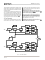
DC-300A II
CHANNEL 1
POWER
I0C
CHANNEL 2
30
30
40
40
20
10
50
20
10
50
0
0
Some models may be exported under the name Amcron.®
®
Applies only to
120 VAC North
American units.
© 1996 by Crown International, Inc., P.O. Box 1000, Elkhart, Indiana
46515-1000 U.S.A. Telephone: 219-294-8000. The DC-300A II is
produced by the Professional Audio Division of Crown International,
Inc. Trademark Notice: Amcron ®, Crown ®, Com-Tech ®, IOC ®, IQ
System ® and Macro-Tech® are registered trademarks of Crown
International, Inc. Other trademarks are the property of their respective
owners.
K80002D9
5/96
3
YEAR
THREE YEAR
FULL WARRANTY
3
YEAR
WORLDWIDE
NORTH AMERICA
SUMMARY OF WARRANTY
The Crown Audio Division of Crown International, Inc., 1718 West
Mishawaka Road, Elkhart, Indiana 46517-4095 U.S.A. warrants to you,
the ORIGINAL PURCHASER and ANY SUBSEQUENT OWNER of each
NEW Crown1 product, for a period of three (3) years from the date of
purchase by the original purchaser (the “warranty period”) that the new
Crown product is free of defects in materials and workmanship, and we
further warrant the new Crown product regardless of the reason for
failure, except as excluded in this Crown Warranty.
SUMMARY OF WARRANTY
The Crown Audio Division of Crown International, Inc., 1718 West Mishawaka
Road, Elkhart, Indiana 46517-4095 U.S.A. warrants to you, the ORIGINAL
PURCHASER and ANY SUBSEQUENT OWNER of each NEW Crown product, for a period of three (3) years from the date of purchase by the original
purchaser (the “warranty period”) that the new Crown product is free of defects
in materials and workmanship. We further warrant the new Crown product
regardless of the reason for failure, except as excluded in this Warranty.
1
Note: If your unit bears the name “Amcron,” please substitute it for the
name “Crown” in this warranty.
ITEMS EXCLUDED FROM THIS CROWN WARRANTY
This Crown Warranty is in effect only for failure of a new Crown product
which occurred within the Warranty Period. It does not cover any product
which has been damaged because of any intentional misuse, accident,
negligence, or loss which is covered under any of your insurance
contracts. This Crown Warranty also does not extend to the new Crown
product if the serial number has been defaced, altered, or removed.
WHAT THE WARRANTOR WILL DO
We will remedy any defect, regardless of the reason for failure (except
as excluded), by repair, replacement, or refund. We may not elect refund
unless you agree, or unless we are unable to provide replacement, and
repair is not practical or cannot be timely made. If a refund is elected, then
you must make the defective or malfunctioning product available to us
free and clear of all liens or other encumbrances. The refund will be equal
to the actual purchase price, not including interest, insurance, closing
costs, and other finance charges less a reasonable depreciation on the
product from the date of original purchase. Warranty work can only be
performed at our authorized service centers. We will remedy the defect
and ship the product from the service center within a reasonable time
after receipt of the defective product at our authorized service center. All
expenses in remedying the defect, including surface shipping costs to
the nearest authorized service center, will be borne by us. (You must bear
the expense of all taxes, duties and other customs fees when
transporting the product.)
HOW TO OBTAIN WARRANTY SERVICE
You must notify us of your need for warranty service not later than ninety
(90) days after expiration of the warranty period. All components must be
shipped in a factory pack. Corrective action will be taken within a
reasonable time of the date of receipt of the defective product by our
authorized service center. If the repairs made by our authorized service
center are not satisfactory, notify our authorized service center
immediately.
DISCLAIMER OF CONSEQUENTIAL AND INCIDENTAL DAMAGES
YOU ARE NOT ENTITLED TO RECOVER FROM US ANY INCIDENTAL
DAMAGES RESULTING FROM ANY DEFECT IN THE NEW CROWN
PRODUCT. THIS INCLUDES ANY DAMAGE TO ANOTHER PRODUCT
OR PRODUCTS RESULTING FROM SUCH A DEFECT.
WARRANTY ALTERATIONS
No person has the authority to enlarge, amend, or modify this Crown
Warranty. This Crown Warranty is not extended by the length of time
which you are deprived of the use of the new Crown product. Repairs and
replacement parts provided under the terms of this Crown Warranty shall
carry only the unexpired portion of this Crown Warranty.
DESIGN CHANGES
We reserve the right to change the design of any product from time to time
without notice and with no obligation to make corresponding changes in
products previously manufactured.
ITEMS EXCLUDED FROM THIS CROWN WARRANTY
This Crown Warranty is in effect only for failure of a new Crown product which
occurred within the Warranty Period. It does not cover any product which has
been damaged because of any intentional misuse, accident, negligence, or
loss which is covered under any of your insurance contracts. This Crown
Warranty also does not extend to the new Crown product if the serial number
has been defaced, altered, or removed.
WHAT THE WARRANTOR WILL DO
We will remedy any defect, regardless of the reason for failure (except as
excluded), by repair, replacement, or refund. We may not elect refund unless
you agree, or unless we are unable to provide replacement, and repair is not
practical or cannot be timely made. If a refund is elected, then you must make
the defective or malfunctioning product available to us free and clear of all liens
or other encumbrances. The refund will be equal to the actual purchase price,
not including interest, insurance, closing costs, and other finance charges less
a reasonable depreciation on the product from the date of original purchase.
Warranty work can only be performed at our authorized service centers or at
the factory. We will remedy the defect and ship the product from the service
center or our factory within a reasonable time after receipt of the defective
product at our authorized service center or our factory. All expenses in
remedying the defect, including surface shipping costs in the United States,
will be borne by us. (You must bear the expense of shipping the product
between any foreign country and the port of entry in the United States and all
taxes, duties, and other customs fees for such foreign shipments.)
HOW TO OBTAIN WARRANTY SERVICE
You must notify us of your need for warranty service not later than ninety (90)
days after expiration of the warranty period. All components must be shipped
in a factory pack, which, if needed, may be obtained from us free of charge.
Corrective action will be taken within a reasonable time of the date of receipt
of the defective product by us or our authorized service center. If the repairs
made by us or our authorized service center are not satisfactory, notify us or
our authorized service center immediately.
DISCLAIMER OF CONSEQUENTIAL AND INCIDENTAL DAMAGES
YOU ARE NOT ENTITLED TO RECOVER FROM US ANY INCIDENTAL
DAMAGES RESULTING FROM ANY DEFECT IN THE NEW CROWN
PRODUCT. THIS INCLUDES ANY DAMAGE TO ANOTHER PRODUCT OR
PRODUCTS RESULTING FROM SUCH A DEFECT. SOME STATES DO
NOT ALLOW THE EXCLUSION OR LIMITATIONS OF INCIDENTAL OR
CONSEQUENTIAL DAMAGES, SO THE ABOVE LIMITATION OR
EXCLUSION MAY NOT APPLY TO YOU.
WARRANTY ALTERATIONS
No person has the authority to enlarge, amend, or modify this Crown Warranty.
This Crown Warranty is not extended by the length of time which you are
deprived of the use of the new Crown product. Repairs and replacement parts
provided under the terms of this Crown Warranty shall carry only the unexpired
portion of this Crown Warranty.
DESIGN CHANGES
We reserve the right to change the design of any product from time to time
without notice and with no obligation to make corresponding changes in
products previously manufactured.
LEGAL REMEDIES OF PURCHASER
No action to enforce this Crown Warranty shall be commenced later than
ninety (90) days after expiration of the warranty period.
LEGAL REMEDIES OF PURCHASER
THIS CROWN WARRANTY GIVES YOU SPECIFIC LEGAL RIGHTS, YOU
MAY ALSO HAVE OTHER RIGHTS WHICH VARY FROM STATE TO STATE.
No action to enforce this Crown Warranty shall be commenced later than
ninety (90) days after expiration of the warranty period.
THIS STATEMENT OF WARRANTY SUPERSEDES ANY OTHERS
CONTAINED IN THIS MANUAL FOR CROWN PRODUCTS.
THIS STATEMENT OF WARRANTY SUPERSEDES ANY OTHERS
CONTAINED IN THIS MANUAL FOR CROWN PRODUCTS.
Telephone: 219-294-8200. Facsimile: 219-294-8301
Telephone: 219-294-8200. Facsimile: 219-294-8301
9/90
9/90
The information furnished in this manual does not include all of the details of design, production, or variations of
the equipment. Nor does it cover every possible situation which may arise during installation, operation or maintenance. If your unit bears the name “Amcron,” please substitute it for the name “Crown” in this manual. If you
need special assistance beyond the scope of this manual, please contact our Technical Support Group.
Crown Audio Division Technical Support Group
57620 C.R. 105, Elkhart, Indiana 46517 U.S.A.
Phone: 800-342-6939 (North America, Puerto Rico and Virgin Islands) or 219-294-8200
Fax: 219-294-8301 Fax Back: 800-294-4094 (North America only) or 219-293-9200
Internet: http://www.crownintl.com
CAUTION
AVIS
RISK OF ELECTRIC SHOCK
DO NOT OPEN
RISQUE DE CHOC ÉLECTRIQUE
N’OUVREZ PAS
TO PREVENT ELECTRIC SHOCK DO
NOT REMOVE TOP OR BOTTOM COVERS. NO USER SERVICEABLE PARTS
INSIDE. REFER SERVICING TO QUALIFIED SERVICE PERSONNEL.
À PRÉVENIR LE CHOC ÉLECTRIQUE
N’ENLEVEZ PAS LES COUVERCLES. IL
N’Y A PAS DES PARTIES SERVICEABLE
À L’INTÉRIEUR. TOUS REPARATIONS
DOIT ETRE FAIRE PAR PERSONNEL
QUALIFIÉ SEULMENT.
Magnetic Field
WARNING
TO REDUCE THE RISK OF ELECTRIC
SHOCK, DO NOT EXPOSE THIS
EQUIPMENT TO RAIN OR MOISTURE!
The lightning bolt
triangle is used to
alert the user to the
risk of electric shock.
CAUTION! Do not locate sensitive high-gain equipment such as preamplifiers or tape decks directly
above or below the unit. Because this amplifier has
a high power density, it has a strong magnetic field
which can induce hum into unshielded devices that
are located nearby. The field is strongest just above
and below the unit.
If an equipment rack is used, we recommend locating
the amplifier(s) in the bottom of the rack and the
preamplifier or other sensitive equipment at the top.
The exclamation point
triangle is used to alert the
user to important operating or
maintenance instructions.
Printed on
recycled paper.
DC-300A II Power Amplifier
CONTENTS
1 Welcome ............................................................................ 7
1.1 Unpacking ................................................................... 7
1.2 Features ...................................................................... 7
2 Facilities ............................................................................ 8
3 Installation ......................................................................... 9
3.1 Mounting ..................................................................... 9
3.2 Cooling ........................................................................ 9
3.3 Wiring ......................................................................... 9
3.3.1 Mode of Operation ............................................ 9
3.3.2 Input Connection ............................................. 11
3.3.3 Output Connection .......................................... 12
3.3.4 Additional Load Protection .............................. 13
3.3.5 AC Mains Power Requirement ......................... 14
4 Operation ......................................................................... 15
4.1 Precautions ............................................................... 15
4.2 Indicators .................................................................. 15
4.3 Controls ..................................................................... 15
4.4 Protection .................................................................. 15
4.5 Fuse Replacement .................................................... 16
5 Technical Information ..................................................... 17
5.1 Principles of Operation .............................................. 17
6 Specifications ................................................................. 18
7 Internal Settings .............................................................. 23
7.1 26 dB Gain vs. 0.775 V Input Sensitivity .................... 23
7.2 Changing the Input Sensitivity to 0.775 V ................... 23
8 Service ............................................................................. 24
8.1 Worldwide Service ..................................................... 24
8.2 North American Service ............................................. 24
8.2.1 Service at a North American Service Center ... 24
8.2.2 Factory Service ............................................... 24
Page 4
DC-300A II Power Amplifier
ILLUSTRATIONS
1.1
2.1
3.1
3.2
3.3
3.4
3.5
3.6
3.7
3.8
3.9
3.10
5.1
6.1
6.2
6.3
6.4
6.5
6.6
6.7
6.8
6.9
7.1
DC-300A II ................................................................................ 7
Facilities .................................................................................... 8
Mounting Dimensions ............................................................... 9
System Connection ................................................................. 10
Input Wiring ............................................................................ 11
Subsonic Filter Capacitors ...................................................... 11
Unbalanced RFI Filters ........................................................... 11
Balanced RFI Filters ................................................................ 11
Wire Size Nomograph ............................................................. 12
Inductive Load (Transformer) Network .................................... 13
Fuse Selector Nomograph ...................................................... 14
AC Mains Voltage Conversion ................................................. 14
Circuit Block Diagram ............................................................. 16
Power Matrix ........................................................................... 19
Nominal Output Impedance .................................................... 20
Nominal Output Phase Angle .................................................. 20
Nominal Damping Factor ........................................................ 20
Nominal Phase Response ....................................................... 21
Nominal Crosstalk ................................................................... 21
Nominal Power Efficiency ........................................................ 21
Nominal Noise Spectrum ........................................................ 22
Nominal Frequency Response ................................................ 22
Main Circuit Board .................................................................. 23
Page 5
DC-300A II Power Amplifier
Rev. 0
Page 6
DC-300A II Power Amplifier
CHANNEL 1
POWER
I0C
CHANNEL 2
30
30
40
40
20
10
50
0
20
10
50
0
Fig. 1.1 DC-300A II
1 Welcome
Congratulations on purchasing a Crown DC-300A II.
Your amplifier is designed to provide reliable operation
with a variety of loads. It is a versatile choice for use in
studios, laboratories, public facilities and on the road.
And the sonic excellence of the DC-300A II makes it a
very good choice for your personal listening pleasure.
Using innovative circuitry, the DC-300A II yields ultralow distortion through a wide range of frequencies from
DC (0 Hz) to 20 kHz. The amplifier’s output transistors
are “direct coupled” to the load so there are no output
capacitors or transformers to compromise its superb
sonic integrity. The tremendous output power of the
DC-300A II enables it to deliver balanced 70 volt output in Bridge-Mono mode without using costly “stepup” transformers. And Crown’s innovative JTS
(Junction Temperature Simulation) circuitry dynamically adjusts the output protection system for unparalleled sonic headroom. Crown further protects your
investment with the industry’s only three year “No-Fault”
full warranty. After reading this manual and learning
about the features, facilities and capabilities of your
amplifier, you will understand why Crown amplifiers are
recognized as the worldwide standard for audio excellence.
For your protection, please send in your warranty registration card and save your bill of sale, as it is your
official proof of purchase.
diately. Only you may initiate a claim with the carrier for
damage resulting during shipment. Even if the unit arrived in perfect condition, as most do, save all packing
materials so you will have them if you ever need to
transport the unit. NEVER SHIP THE UNIT WITHOUT
THE FACTORY PACK.
1.2 Features
Your dual channel (stereo) amplifier can be configured
for higher-powered single channel operation. It also
provides the following features:
❏ AB+B class circuitry for maximum efficiency with minimum crossover “notch” distortion.
❏ IOC ® (Input/Output Comparator) alerts of distortion exceeding 0.05% to provide proof of performance.
❏ Ultra-low harmonic and intermodulation distortion result
in the best dynamic transfer function in industry.
❏ Very low noise level and wide dynamic range exceed
digital audio standards.
❏ Exclusive JTS (Junction Temperature Simulation) circuitry protects the output devices and provides exceptional dynamic headroom.
❏ High damping factor gives you greater loudspeaker motion control.
❏ Bridge-Mono output can drive 70 volt “constant voltage”
lines without expensive, distortion-producing “step-up”
transformers.
❏ Convection cooling with integrated heat sink/chassis design for maintenance-free operation.
1.1 Unpacking
❏ Mounts in a standard 19 inch (48.3 cm) rack.
Please unpack and inspect your new amplifier for any
damage that may have occurred during transit. If damage is found, notify the transportation company imme-
❏ Three year “No-Fault” full warranty protects your investment and guarantees the specifications of units in North
America and other select countries.
Page 7
DC-300A II Power Amplifier
CHANNEL 1
POWER
I0C
CHANNEL 2
30
30
40
40
20
10
50
20
10
50
0
A
B
C
D
C
E
F
OUTPUT
OUTPUT
CHANNEL 2
CHANNEL 1
2 INPUT 1
G D
0
H I
H
G
LINE
FUSE AC
DUAL MONO
® INTERNATIONAL, INC.
ELECTRONIC EQUIPMENT
ELKHART, IN 46517
MADE IN U.S.A.
SERIAL NUMBER
0000
000000
Fig. 2.1 Facilities
2 Facilities
A. Power Indicator
This indicator glows when the amplifier is turned on.
B. Power Switch
This push button turns the DC-300A II on and off. The
unit has no turn-on delay and minimal thumps. Always
turn the amplifier on last so the turn-on transients of
other components will not be amplified.
C. Input Jacks
An unbalanced ¼ inch phone jack is used for input to
each channel. Do not use the channel 2 input in BridgeMono mode.
D. Output Jacks
5-way binding posts provide output from each channel. Use banana plugs, spade lugs or bare wire to connect loudspeaker cables. In Bridge-Mono mode,
connect the positive (+) loudspeaker terminal to the
positive (+) channel 1 output and the negative (–) loudspeaker terminal to the positive (+) channel 2 output.
E. Dual-Mono Switch
Facing the back of the amplifier, slide this switch to the
left for Dual (stereo) mode and to the right for BridgePage 8
Mono mode. In Bridge-Mono mode, the channel 2 input should not be used, its level control should be
turned down and only balanced (ungrounded) loads
should be connected to the output (see section 3.3.1).
F. Fuse Holder
The AC line is safely fused. Use a 10 amp, 250 volt,
type AB fuse for 100 and 120 VAC operation, or a
5 amp, 250 volt, type MTH fuse for 200, 220 and
240 VAC units (see Sections 3.3.5 and 4.5).
G. Level Controls
The output level of each channel is adjusted with these
controls. Turn the channel 2 level control down completely when using Bridge-Mono mode.
H. Power Cord
The unit has a grounded, three wire AC cord and plug.
I. IOC Indicators
The red Input/Output Comparator (IOC) indicators provide proof of distortion-free performance. Normally off,
they flash in the rare event that the output waveform
differs from the input by 0.05% or more.
DC-300A II Power Amplifier
3 Installation
Your amplifier is designed for standard 19 inch
(48.3 cm) rack mounting. Before mounting, determine
whether you need to change the amplifier’s internal settings for your application.
Your amplifier’s internal settings make it possible to
change the input sensitivity from the default 26 dB gain
to a sensitivity of 0.775 volts. If you need to operate
your amplifier with an input sensitivity of 0.775 volts, or
if you want more information on input sensitivity, please
refer to Section 7 before proceeding.
3.1 Mounting
The DC-300A II can be mounted into a standard
19 inch (48.3 cm) wide equipment rack. It occupies
7 inches (17.8 cm) of vertical rack space. Mounting
screws and washers are provided with the unit. Although units can be stacked, this practice is not recommended. Instead, mount multiple units in a rack
leaving air space between them. Also, before mounting the amplifier, please read about the amplifier’s cooling requirements in the section that follows.
1.5 in
3.8 cm
5.5 in
14 cm
CHANNEL 1
POWER
I0C
3.3 Wiring
Figure 3.2 depicts three of the most common ways to
install a DC-300A II in a sound system. All input and
output jacks are located on the back panel. Please use
care in making connections, selecting signal sources
and controlling the output level. The load you save may
be your own! Crown is not liable for any damage done
to loads due to careless amplifier usage and deliberate overpowering.
3.3.1 Mode of Operation
The DC-300A II may be operated in either Dual (stereo) or Bridge-Mono mode by setting the Dual-Mono
switch on the back panel of the amplifier. There are
very important wiring differences between these two
modes which are discussed next.
CHANNEL 2
30
7 in
17.8 cm
mounting, we recommend that you allow a 1.75 inch
(4.45 cm) space above and below the unit. If you
mount it with the front panel up, be sure to provide air
space above and below the unit. Inadequate cooling
can cause the built-in thermal protection circuitry to be
activated prematurely. Overheating like this can also
cause the front panel to become warm. Applications
requiring sustained use at high output power levels
may require the installation of a cooling fan.
30
40
40
20
10
50
0
20
10
50
0
19 in
48.3 cm
10.5 in
26.7 cm
DUAL
Dual mode installation is intuitive. The channel 1 input
feeds the channel 1 output, and the channel 2 input
feeds the channel 2 output. To put the amplifier in Dual
mode, turn off the amplifier and slide the Dual-Mono
switch to the left as you face the amplifier’s back panel
(see Figure 3.2). Be careful not to short the outputs
together, and observe correct loudspeaker polarity.
CAUTION: Do not tie the two outputs together.
Never tie an output to another amplifier’s output.
10.5 in
26.7 cm
0.875 in
2.2 cm
Fig. 3.1 Mounting Dimensions
3.2 Cooling
Your amplifier does not have a cooling fan. To prevent
overheating, sufficient ventilation is required. Equipment racks or cabinets should have perforated top and
bottom panels. This is especially important if more than
one amplifier will be mounted in the same rack. When
MONO
Amplifier installation in Bridge-Mono mode is very different. First, only the channel 1 input should be used.
DO NOT USE THE CHANNEL 2 INPUT. For best results, disconnect all channel 2 input sources and turn
the channel 2 level control fully counterclockwise (off).
Note: The channel 2 input and level control are not defeated in bridge-mono mode. A signal fed to channel 2
will work against the signal feeding channel 1.
To activate Bridge-Mono, move the Dual-Mono switch
to the right as you face the amplifier’s back panel. Both
Page 9
DC-300A II Power Amplifier
–
–
+
+
CHANNEL 2
CHANNEL 1
DUAL MODE
OUTPUT
OUTPUT
CHANNEL 2
CHANNEL 1
2 INPUT 1
LINE
FUSE AC
DUAL MONO
CHANNEL 1
INTERNATIONAL, INC.
ELECTRONIC EQUIPMENT
®
ELKHART, IN 46517
MADE IN U.S.A.
SERIAL NUMBER
0000
000000
CHANNEL 2
MIXER
DC-300A II AMP
DUAL
MONO
–
+
CHANNEL 2 (+)
CHANNEL 1 (+)
BRIDGE-MONO
MODE (METHOD 1)
OUTPUT
OUTPUT
CHANNEL 2
CHANNEL 1
2 INPUT 1
LINE
FUSE AC
DUAL MONO
CHANNEL 1
INTERNATIONAL, INC.
ELECTRONIC EQUIPMENT
®
ELKHART, IN 46517
MADE IN U.S.A.
SERIAL NUMBER
0000
000000
MIXER
DC-300A II AMP
DUAL
MONO
+
–
–
+
CHANNEL 2
(POLARITY MUST
BE INVERTED)
CHANNEL 1
BRIDGE-MONO
MODE (METHOD 2)
OUTPUT
OUTPUT
CHANNEL 2
CHANNEL 1
2 INPUT 1
LINE
FUSE AC
DUAL MONO
CHANNEL 1
INTERNATIONAL, INC.
ELECTRONIC EQUIPMENT
®
ELKHART, IN 46517
MADE IN U.S.A.
SERIAL NUMBER
0000
000000
MIXER
DC-300A II AMP
DUAL
MONO
Fig. 3.2 System Connection
Page 10
DC-300A II Power Amplifier
outputs will receive the channel 1 input. The channel 2
output is inverted so it can be bridged with channel 1.
dB
0
–5
There are two different ways to connect Bridge-Mono
wiring. The most common method is to connect the
positive (+) output of channel 1 to the positive (+) loudspeaker lead, and the positive (+) output of channel 2
to the negative (–) loudspeaker lead (see Figure 3.2).
The negative amplifier outputs are not used.
In Bridge-Mono mode, it is also possible to connect a
loudspeaker to each output channel, however, the output of channel 2 is inverted. To compensate for this,
you can invert the polarity of the channel 2 output wiring. First, connect a loudspeaker to channel 1 as you
would normally. Then, connect a loudspeaker to channel 2 so its positive (+) output goes to the negative (–)
loudspeaker terminal, and negative (–) output goes to
the positive (+) loudspeaker terminal.
CAUTION: Only connect balanced loads to a bridgemono output. Output lines must be isolated from
ground or severe oscillations may occur.
3.3.2 Input Connection
The unbalanced ¼ inch phone inputs have a typical
impedance of 25 K ohms. They accept the line level
output from most devices. Figure 3.3 shows how to
properly wire both balanced and unbalanced lines.
+
FROM
UNBALANCED
SOURCE
27
µf
f
1µ
.2
µf
.05
µf
–15
0.1 Hz
1 Hz
10 Hz
100 Hz
1 kHz
Frequency
Fig. 3.4 Subsonic Filter Capacitors
are sensitive to high frequencies. Extremely high RF
levels can also cause your amplifier to prematurely activate its protection circuitry, resulting in inefficient operation. RF can be introduced into a signal by local
radio stations and from the bias signal of many tape
recorders. To prevent this from happening, place an
appropriate low-pass filter on the input(s). Some examples are shown below for unbalanced wiring.
1.8 K ohm
Source
.003
µf
3.9 mH
.015
µf
0
6 dB/octave
To
Amp
A
12 dB/octave
5 mH
.018
µf
–10
B
GND
B
R 600 ohm
Source
dB
GND
A
R 600 ohm
Source
To
Amp
C
–20
To
Amp
GND
C
4 kHz
10 kHz
Note: A low source impedance (R) can be
increased to 600 ohms with an appropriate resistor.
+
40 kHz
100 kHz
Frequency
Fig. 3.5 Unbalanced RFI Filters
SHIELD
UNBALANCED
INPUT
–
+
+
FROM
BALANCED
SOURCE
–10
DROP
SHIELD
UNBALANCED
INPUT
For balanced input wiring, use one of the examples in
Figure 3.6. Filters A, B and C correspond to the unbalanced filters above. Filter D also incorporates the subsonic filter described previously.
+
A
–
SOLVING INPUT PROBLEMS
Sometimes large subsonic (subaudible) frequencies
are present in the input signal. These can damage
loudspeakers by overloading or overheating them. To
attenuate such frequencies, place a capacitor in series with the input signal line. The graph in Figure 3.4
shows some possible capacitor values and how they
affect frequency response. Use only a low-leakage paper, mylar or tantalum capacitor.
+
+
.003
µf
Balanced In
Fig. 3.3 Input Wiring
Another problem to avoid is the presence of large levels of radio frequencies or RF in the input signal. Although high RF levels may not pose a threat to the
amplifier, they can burn out tweeters or other loads that
910 Ω
Balanced Out
–
910 Ω
1.8 mH
B
Balanced In
+
.015
µf
–
Balanced Out
–
1.8 mH
2.5 mH
+
C
Balanced In
+
.018
µf
–
Balanced Out
–
2.5 mH
0.47 Film 1.8 mH
+
D
Balanced In
+
.015
µf
–
Balanced Out
–
0.47 Film 1.8 mH
Fig. 3.6 Balanced RFI Filters
Page 11
DC-300A II Power Amplifier
A third problem to avoid is hum. The two most common sources of hum in an audio system are inductive
coupling and ground loops.
Inductive coupling can occur when input cables are
subjected to a magnetic field from a power cord or
power transformer. One way to prevent inductive coupling is to lace the input cables together along their
length and route them as far away as possible from
power transformers and power cords. The use of
shielded pair cable is another effective way to reduce
or eliminate hum resulting from inductive coupling.
Ground loops often result when two or more devices
are improperly grounded. This causes undesirable
stray currents that may produce hum in the output. The
best way to avoid ground loops is to ensure that all
system devices are plugged into the same power strip.
In addition, make sure that all cable shields are
grounded at one end only.
Input and output grounds are sometimes tied together
for testing or metering. This can cause feedback oscillation from load current in the test loop. In some
systems, even the AC power line may provide this feedback path. Proper grounding, input isolation and isolation of common AC devices in the system is good
practice.
HOW TO DETERMINE
APPROPRIATE WIRE GAUGE
It is important to use loudspeaker cables of sufficient
gauge (thickness) for the length used. The resistance
introduced by inadequate loudspeaker cables will reduce both the output power and the motion control of
the loudspeakers. The latter problem occurs because
the damping factor decreases as loudspeaker cable
resistance increases. This is very important because
the amplifier’s excellent damping factor can easily be
negated by using insufficient loudspeaker cables.
Use the nomograph and the procedure that follow to
find the recommended wire gauge (AWG or American
Wire Gauge) for your system.
40
30
RL
LOAD
.04
RESISTANCE
(ohms)
.06
RL
RS
DAMPING
.2
50
.4
.6
20
1
10
2-COND.
CABLE
5
20
50
100
5
2
2000
9
2
1. Use only shielded cable. Cables with
higher density shields are better. Spiral
wrapped shield is not recommended.
4
5000
3. Keep signal and high level wiring apart.
4. Turn off the unit before making connections. Crown is not liable for injury or damage due to overdriven components.
3.3.3 Output Connection
Consider the power-handling capacity of your load before connecting it. Crown is not liable for damage incurred at any time due to a load being overpowered.
The use of loudspeaker protection fuses is highly recommended (see Section 3.3.4). Also, please pay close
attention to the precautions in Section 4.1.
Page 12
50
10
#28
#26
#24
#22
#20
10
5
#18
#16
#14
#12
#10
1
#8
#6
.5
#4
.1
#0
#00
#0000
6
6
#2
.05
5
20
4
40
3
2. Avoid unbalanced lines longer than 10 feet
(3 meters).
1
100
1000
8
Input Wiring Tips
500
200
500
7
COPPER
WIRE
(AWG)
1000
10
10
ANNEALED
5000
(feet)
20
15
8000
(ohms/1000 ft.)
.1
FACTOR
100
RS
SOURCE
RESISTANCE
(ohms)
.01
Example Shown:
RL = 8 ohms; RS = 0.16 ohms or D.F. = 50;
Cable Length = 50 ft.; answer: #12 wire
2
Fig. 3.7 Wire Size Nomograph
1. Note the load resistance of the loudspeakers connected to each
channel of the amplifier. Mark this value on the “Load Resistance”
line of the nomograph.
2. Choose an acceptable system damping factor and mark it on the
“Damping Factor” line. Your amplifier can provide an excellent
damping factor of 750 or more from DC to 400 Hz in Dual mode
with an 8 ohm load. In contrast, typical damping factors are 50 or
lower. Higher damping factors yield lower distortion and greater
motion control over the loudspeakers. A common damping factor
for commercial applications is between 50 and 100. Higher
damping factors may be desirable for live sound, but long cable
lengths often limit the highest damping factor that can be
achieved practically. (Under these circumstances, Crown’s
IQ System ® is often used with Crown’s premium Macro-Tech,®
Com-Tech ® and Reference series amplifiers for easy monitoring
and control of units located very near the loudspeakers.) In
recording studios and home hi-fi, a damping factor of 500 or more
is desirable.
DC-300A II Power Amplifier
3. Draw a line through the two points with a pencil, and continue until
it intersects the “Source Resistance” line.
4. On the “2-Cond. Cable” line, mark the length of cable run.
5. Draw a pencil line from the mark on the “Source Resistance” line
through the mark on the “2-Cond. Cable” line, and on to intersect
the “Annealed Copper Wire” line.
6. The required wire gauge for the selected wire length and
damping factor is the value on the “Annealed Copper Wire” line.
Note: Wire size increases as the AWG gets smaller.
7. If the size of the cable exceeds what you want to use, (1) find a
way to use shorter cables, (2) settle for a lower damping factor, or
(3) use more than one cable for each line. Options 1 and 2 will
require the substitution of new values for cable length or damping
factor in the nomograph. For option 3, estimate the effective wire
gauge by subtracting 3 from the apparent wire gauge every time
the number of conductors of equal gauge is doubled. So, if #10
wire is too large, two #13 wires can be substituted, or four #16
wires can be used for the same effect.
Use Good Connectors
1. To prevent possible short circuits, do not
use loudspeaker cables with exposed
male connectors.
2. Do not use connectors that might accidentally tie two channels together when making or breaking connections, such as a
standard three wire stereo phone plug.
3. Never use connectors that can be plugged
into an AC power receptacle.
4. Avoid connectors with low current-carrying
capacity.
5. Do not use connectors with any tendency
to short.
filters described in Section 3.3.2.
5. Install the input wiring according to the instructions in Section 3.3.2.
Another problem to avoid is the presence of large subsonic currents when primarily inductive loads are
used. Examples of inductive loads are 70 volt step-up
transformers and electrostatic loudspeakers.
Inductive loads can appear as a “short” at low frequencies, causing the amplifier to produce large low-frequency currents and unnecessarily activate its
protection circuitry. Always take the precaution of installing a high-pass filter on the amplifier inputs when a
predominantly inductive load is used. A three pole (18
dB per octave) filter with a –3 dB frequency of 50 Hz is
recommended. (Depending on the system, it may be
preferable to use a filter with a higher –3 dB frequency.)
Such a filter can eliminate the subsonic frequency
problems mentioned in Section 3.3.2.
Another way to prevent the amplifier from activating its
protection systems early and protect inductive loads
from large low-frequency currents is to connect a 590
to 708 µF nonpolarized capacitor and a 4 ohm, 20 watt
resistor at the output of the amplifier in series with the
positive (+) lead of the transformer. This is depicted in
Figure 3.8.
4-ohm, 20-watt
Resistor
+
From
Amplifier
Output
–
SOLVING OUTPUT PROBLEMS
Sometimes high frequency oscillations occur which
can cause your amplifier to prematurely activate its protection circuitry, resulting in inefficient operation. The
effects of this problem are similar to the effects of the
RF problem described in Section 3.3.2. To prevent high
frequency oscillations:
1. Lace loudspeaker cables together to minimize
the chance of them acting like an antenna to
transmit or receive high frequencies that can
cause oscillation.
2. Keep the speaker cables well separated from
input cables.
3. Never connect the amplifier’s input and output
grounds together.
4. Install a low-pass filter on each input like the RF
590 to 708 µf Capacitor
120 VAC, N.P.
+
Inductive
Load
–
Fig. 3.8 Inductive Load (Transformer) Network
Note: The components shown in Figure 3.8 are commonly available from most electronic supply stores.
3.3.4 Additional Load Protection
Because your amplifier can generate enormous power,
you may want to protect loudspeakers or other sensitive loads from excessive power that could result in
damage. A common way to do this is to put a fuse in
series with the load. This may be accomplished by using a single fuse to protect the entire system, or by
fusing each driver.
Fuses help prevent damage due to prolonged overload, but provide essentially no protection against
damage from large transients. To minimize this problem, use high-speed instrument fuses such as the
Page 13
DC-300A II Power Amplifier
Littlefuse 361000 series. If the loudspeaker is only susceptible to damage caused by prolonged overload
(such as overheating), use a fuse or circuit breaker
having the same slow thermal response as the loudspeaker itself (such as a slow-blow fuse).
The nomograph in Figure 3.9 shows fuse size versus
loudspeaker peak power rating. It can be used to determine the size of the required fuse.
1.0
1.2
1.6
20
3000
15
2000
1000
8
9
Answer: Fuse = 1.5 A
150
2
100
80
1.5
60
1
40
.8
10
30
.6
12
20
.5
25
30
.3
.2
.15
LOUDSPEAKER RATING
20
15
.4
FUSE
(amps)
16
LOUDSPEAKER IMPEDANCE
(ohms)
14
.1
40
.08
10
8
6
4
3
2
1.5
BLK
Example:
Impedance = 8 ohms.
Peak Power = 75 W
BLU–YEL
6
IMPORTANT: Use only a 5 amp, 250 volt, type MTH
fuse for 200, 220 or 240 VAC operation; use only a
10 amp, 250 volt, type AB fuse for 100 or 120 VAC
operation.
BLK–GRN
200
A
B
C
D
E
F
A
B
C
D
E
F
A
B
C
D
E
F
A
B
C
D
E
F
A
B
C
D
E
F
100 V
PEAK MUSIC POWER
(watts)
300
3
(Typically 4 times the continuous average power)
400
4
WHT
600
5
5
7
7. Repeat steps 1 and 2 in reverse order to reassemble the unit.
800
6
4
6. Carefully check all connections.
1500
8
3
4. Change the appropriate jumpers for the desired
operating voltage (see Figure 3.10).
YEL–RED
10
3. Find the power transformer. The terminal strip
with six connector tabs is wired to the transformer.
GRN–WHT
2.5
2. Remove the perforated top cover by removing
the 12 phillips screws that hold it in place.
5. Make sure the proper fuse is installed. Use only
a 5 amp, 250 volt, type MTH fuse for AC mains
of 200 volts or more; use only a 10 amp, 250
volt, type AB fuse for AC mains below 200 volts.
1.4
2
1. Turn the amplifier off and disconnect it from the
AC mains.
120 V
1
Fig. 3.9 Fuse Selector Nomograph
WARNING: Risk of electric shock! Only a qualified
technician should attempt to alter your amplifier’s
AC mains voltage configuration.
To operate your amplifier at a different line voltage, you
will need a phillips screwdriver. Then follow these steps:
Page 14
220 V
240 V
WHT
Five standard line voltages are supported, including
100, 120, 200, 220 and 240 VAC. The unit may be operated at AC mains frequencies from 50 to 400 Hz. The
model-voltage sticker on the back panel indicates the
unit’s factory configuration.
200 V
ORN
3.3.5 AC Mains Power Requirement
All units have a standard three wire, grounded AC cord
and plug as specified by UL requirements for North
American 120 VAC, 60 Hz units. Note: Crown assumes
no liability whatsoever for ungrounded operation, nor
for violation of UL or local electrical codes.
Fig. 3.10 AC Mains Voltage Conversion
DC-300A II Power Amplifier
4 Operation
4.1 Precautions
4.2 Indicators
Your amplifier is protected from all external faults. Even
so, you should take the following precautions:
Your amplifier has three front panel indicators. The yellow power indicator glows when the amplifier is turned
on and the unit is receiving power.
1. When the level of an input source is uncertain,
or an audio component has not been previously
used with your amplifier, always begin with the
level controls at a minimum and gradually increase them while monitoring the output level.
This approach helps avoid loudspeaker blasts.
2. Don’t forget, your amplifier does not have a turn
on delay. Beware of turn-on transients from
other equipment ahead of the amplifier—always
turn the amplifier on after other equipment has
stabilized.
The IOC (Input/Output Comparator) indicators work
like sensitive distortion meters. Each channel has a red
LED (light emitting diode) that flashes when distortion
of any kind exceeds 0.05%. They typically glow for
about one minute after the AC power is turned off.
4.3 Controls
3. Turn off the amplifier and unplug it from the AC
mains before replacing the fuse, installing an input sensitivity jumper or changing the position
of the Dual-Mono switch.
A power switch and level controls are located on the
front panel. When you power up the amplifier, remember that the unit does not have a turn-on delay. Each
channel has its own level control which is used to adjust the desired output level. Both level controls are
used in Dual mode, but only the channel 1 control
should be used in Bridge-Mono mode.
4. There are important differences between Dual
and Bridge-Mono mode wiring (refer to Section
3.3.1).
The amplifier is switched between Dual and BridgeMono operation with the Dual-Mono switch located on
the back panel of the amplifier (see Section 2).
5. Operate the amplifier with the correct fuse: a 5
amp, 250 volt, type MTH fuse for units configured for 200 volt or higher AC mains, and a 10
amp, 250 volt, type AB fuse for units configured
for AC mains of less than 200 volts.
The unit’s input gain is 26 dB as determined by 1%
precision resistors in the feedback loop. This can be
changed to a sensitivity of 0.775 volts by following the
instructions in Section 7.
6. Be careful when driving a transformer-coupled
device (such as an electrostatic loudspeaker)
or other loads that appear as a low-frequency
short circuit (less than 3 ohms) without a series
isolating capacitor. Such operation may damage the load and needlessly activate the
amplifier’s V-I limiting.
4.4 Protection
7. Operate the amplifier with AC mains of no more
than 10% above the selected line voltage and at
the specified line frequency (50 to 400 Hz).
Protection against shorted and low impedance loads
is provided by the JTS (Junction Temperature Simulation) circuitry. This circuitry instantaneously limits the
amplifier’s output voltage to the maximum safe level for
the output transistors. With a loudspeaker, you can tell
the amplifier has activated load protection because it
causes audible distortion. The noise might be compared to crossover “notch” distortion or a snapping
sound, depending on the load characteristics. Loudspeaker systems with impedances of 4 ohms or higher
will not activate this system.
8. Never connect the output to a power supply
output, battery or power main. This can cause
electric shock and damage to the amplifier.
9. Do not expose the amplifier to corrosive chemicals such as soft drinks, lye, salt water, etc.
10. Do not tamper with the circuitry. Unauthorized
circuit changes invalidate the warranty.
11. Do not short the ground lead of an output to the
input signal ground or oscillations may result.
12. We recommend that you avoid using the amplifier with frequencies above 30 kHz.
Your amplifier is protected against all the common hazards that plague high-power amplifiers, including
shorted, open and mismatched loads; overloaded
power supplies, chain destruction phenomena, input
overload and high-frequency blowups.
All voltage amplification circuitry is designed to limit
current. So in the extremely unlikely event of a device
failure, the amplifier will prevent further damage.
Page 15
DC-300A II Power Amplifier
The input stages are protected from overload by series
resistors. The unit also features a controlled slew rate
and the JTS limiter that protect the amplifier from highfrequency blowups.
A thermal switch is mounted on each heat sink to protect your amplifier against overheating. If either heat
sink becomes too hot, the AC mains power will be interrupted until the temperature falls to a safe level and
the unit resets itself. If the unit overheats, it will not produce any output and it will be very warm to touch.
4.5 Fuse Replacement
An AC line fuse is located beside the power cord on
the back panel of the amplifier. To replace the fuse,
INPUT
OUTPUT
COMPARATOR
–
CHANNEL 1
INPUT
+
INPUT
AMP
SIGNAL
TRANSLATOR
turn off the power switch and disconnect the power
plug from the AC mains. Unscrew the cap of the fuse
holder and remove the fuse.
CAUTION: The fuse holder has power even when
the power switch is turned off. Always disconnect
AC power before replacing fuses.
Replace the fuse with a 10 amp, 250 volt, type AB fuse
for units operating with an AC mains voltage less than
200 volts, or a 5 amp, 250 volt, type MTH fuse for units
operating with an AC mains voltage of 200 volts or
more. Reassemble in reverse order.
WARNING: Never replace the original fuse with one
rated for higher current (amperage).
POSITIVE
DRIVER
STAGE
POSITIVE
OUTPUT
STAGE
BIAS
SERVO
PROTECTION
CIRCUIT
NEGATIVE
DRIVER
STAGE
NEGATIVE
OUTPUT
STAGE
LAST
VOLTAGE
AMP
10 K
CHANNEL 1
OUTPUT
DUAL
MONO
MONO
CHANNEL 2
OUTPUT
INPUT
OUTPUT
COMPARATOR
–
CHANNEL 2
INPUT
+
INPUT
AMP
SIGNAL
TRANSLATOR
POSITIVE
DRIVER
STAGE
POSITIVE
OUTPUT
STAGE
BIAS
SERVO
PROTECTION
CIRCUIT
NEGATIVE
DRIVER
STAGE
NEGATIVE
OUTPUT
STAGE
LAST
VOLTAGE
AMP
Fig. 5.1 Circuit Block Diagram
Page 16
DC-300A II Power Amplifier
5 Technical Information
5.1 Principles of Operation
The DC-300A II has input amplifiers that are powered
by zener-regulated power supplies. The bias regulators are also powered by zener-regulated current
sources with the result that line voltage variations do
not cause noise or distortion due to misbiasing.
bias current in the output transistors. The benefit is
maximum efficiency, minimum crossover notch distortion and minimum thermal dissipation at idle. The output circuit does not have a critical temperature
tolerance, so there is no bias current adjustment.
The power supply is designed for continuous duty and
supports 1 kilowatt loading. The power transformer
weighs 25 pounds (11.3 kg) and is made of a very
special steel. The main DC supplies are full-wave supplies with heavy duty, heat-sinked diodes. Computer
grade electrolytic capacitors furnish over 48 joules of
energy storage. A higher voltage at low current is derived from a half-wave voltage-doubling circuit. This is
used in the amplifier’s driver circuit.
In the AB+B output circuit, the driver transistors carry
the bias current while the output transistors serve only
as boosters. The output transistors sense when the
driver transistors are delivering significant current to
the load, then they take over and deliver the large current levels.
The amplifier has two direct-coupled amplifier circuits
employing dual IC opamps and silicon transistors in all
stages. Because of its direct coupling, the amplifier
has a perfectly flat frequency and phase response extending from DC (0 Hz) to 20 kHz. Flat-to-DC response
not only results in low-frequency amplification with absolutely no phase distortion, but it also offers excellent
overload characteristics. DC frequency response is
combined with ultra-low noise and intermodulation distortion to deliver the classic rendering of a “straight
wire with gain.” In fact, before the advent of Crown’s
Reference series amplifiers, the DC-300A II enjoyed a
reputation of being the most accurate amplifier available.
The two low-noise IC opamps have a large gain bandwidth. Using them as the input voltage amplifiers results in a maximum amount of feedback which reduces
distortion to exceptionally low levels.
The output stage is a quasi-complementary format
employing Crown’s AB+B class circuitry which uses no
The IOC (Input/Output Comparator) circuitry works
with the error correcting signal of the main opamp. If a
small non-linearity exists in the amplifier, an error signal
appears at the output of the main opamp via the unit’s
feedback loop. This produces an abnormally high
value, exceeding the threshold of the IOC and illuminating the LED. Because transient overload can happen very quickly, a pulse stretching circuit is added so
you can see the LED flash.
Protection against shorted and low impedance loads
is provided by Crown’s JTS (Junction Temperature
Simulation) control circuit. It functions as an automatic
current limiter at audible frequencies and as a V-I limiter at subaudible frequencies. The threshold of current limiting is dependent on the history of the signal,
yet the threshold of the limiting with no signal is high
enough to allow full power tone bursting. The result is
maximum protection with trouble-free output power
without an inventory of special fuses or cumbersome
load-matching techniques.
The DC-300A II gives you the highest quality in both
circuitry and components. It should provide you with a
lifetime of trouble-free service.
Page 17
DC-300A II Power Amplifier
6 Specifications
Note: The following specifications apply to units configured for
120 VAC, 60 Hz operation in Dual mode with 8 ohm loads and an
input sensitivity of 26 dB gain unless otherwise specified.
Performance
Frequency Response: ±0.1 dB from DC to 20 kHz at
1 watt (see Figure 6.9).
Phase Response: +0/–15 degrees from DC to 20 kHz
at 1 watt (see Figure 6.5).
Signal-to-Noise Ratio: (20 Hz to 20 kHz) At least
110 dB below rated maximum average power (see Figure 6.8).
Harmonic Distortion (THD): Less than 0.001% from
20 to 400 Hz and increasing linearly to 0.05% at 20 kHz
at rated maximum average power.
Intermodulation Distortion (IMD): (SMPTE-IM 60 Hz
and 7 kHz) Less than 0.05% from 0.01 to 0.25 watts,
and less than 0.01% from 0.25 to rated maximum average power.
Damping Factor: Greater than 750 from DC to 400 Hz
(see Figure 6.4).
selectable transformer taps for 100, 120, 200, 220 and
240 VAC (±10%) operation. Draws 40 watts or less at
idle and 500 watts at rated power.
Controls
Independent level controls and power switch are located on the front panel. Non-interacting DC balance
controls are mounted on main PC board under electronics cover. A Dual-Mono switch is located below the
input jacks on the back panel.
Indicators
Power: This yellow indicator remains lit while the amplifier is turned on.
IOC: These red indicators are normally off. They flash
in the unlikely event of the output waveform differing
from the input by 0.05% or more. They act as sensitive
distortion indicators providing proof of performance.
Input/Output
Input Impedance: Nominally 25 K ohm.
Crosstalk: See Figure 6.6.
Input Sensitivity: 1.75 volts ±2% for 310 watts into
16 ohms.
Slew Rate: Greater than 8 volts per microsecond.
Input: ¼ inch unbalanced phone jacks.
Voltage Gain: (At maximum output) 20.6:1 ±2% or
26.3 dB ±0.2 dB. (Refer to Section 7 for information on
the 0.775 volt sensitivity setting.)
Output: Color coded binding posts (banana jacks).
Power
Also see the power matrix. Note: Maximum average
power per channel at 1 kHz with 0.1% or less THD.
Dual mode (both channels driven):
305 watts into 4 ohms.
175 watts into 8 ohms.
100 watts into 16 ohms.
Bridge-Mono mode:
610 watts into 8 ohms.
355 watts into 16 ohms.
Load Impedance: Rated for 16, 8 and 4 ohm use. Safe
with all types of loads.
Power Supply: 1 kilowatt transformer with computergrade filter capacitors storing over 48 joules of energy.
Power Efficiency: See Figure 6.7.
Power Requirements: Requires 50 to 400 Hz AC with
Page 18
Output Impedance: Less than 7 milliohms in series
with less than 3 microhenries. See Figure 6.2.
Output Signal
Dual: Unbalanced, dual channel.
Bridge-Mono: Balanced, single channel.
Protection
Overall Protection: AC line fused. Thermal switch in
AC line protects against overheating caused by insufficient ventilation. Controlled slew rate voltage amplifiers protect overall amplifier against RF burnouts. Input
overload protection is furnished by internal resistance
at inputs of amp.
Amplifier Output Protection: Short, mismatch, and
open circuit proof. Limiting is instantaneous with no
flyback pulses, thumps, cutout, etc. No premature limiting on transients.
Turn-On: Instantaneous, with minimum thumps and no
program delay.
DC-300A II Power Amplifier
Construction
Dimensions: 19 inch (48.3 cm) standard rack mount
width (EIA std. RS-310-B); 7 inch (17.8 cm) height; 10.5
inch (26.7 cm) depth behind front mounting surface;
0.625 inch depth in front of mounting surface.
chassis and top cover.
Chassis: All aluminum construction for maximum heat
conduction and minimum weight. Heavy aluminum
front panel is a single extrusion.
Weight: Net weight is 40 pounds, 11 ounces (18.5 kg);
Shipping weight is 45 pounds, 0 ounces (20.3 kg).
Heat Sinking: Massive black-anodized heat sinks are
thermally joined with the chassis, thereby utilizing the
entire amplifier as a heat sink.
Finish: Carbide black front panel, splatter-coat black
Crown specifications are guaranteed for three years.
In an effort to provide you with as much information as possible about the high power-producing capabilities of your amplifier, we have created
the following Power Matrix. All specifications found in these tables are valid for 120 VAC, 60 Hz models and are guaranteed for three years. Some
spaces in the tables are left blank because we do not provide this same guarantee for those conditions—however, your amplifier will perform well
under all conditions listed in the table.
Power Specifications
When measuring power, 0.1% THD appears to be the industry standard for distortion. One of the maximum average power columns shown in the
power matrix is measured when THD rises to 0.1% so you can easily compare Crown specifications to those of other manufacturers. But this high
level of distortion actually allows for some clipping which is undesirable. Full-bandwidth maximum average power measured at 0.05% THD
provides more reasonable, non-clipped conditions. Crown provides this specification with the hope that other manufacturers will also start
providing specifications that correspond to the way amplifiers are used in the real world—without a clipped input signal.
Many manufacturers publish power specifications with a tolerance of ±1 dB or worse. That means their amplifier can deviate more than 20% in
output! A 100 watt amplifier would meet their specification if it only produced 79.4 watts. Other manufacturers qualify their specs by saying they
are “typical,” “subject to manufacturing tolerances,” “single channel driven” or that they are specified with “fuses bypassed.” Each of these
statements effectively removes any performance guarantee. We take a different approach at Crown—our published specifications are guaranteed for three years. Further, because our “in-house” specs are more stringent than our published specs, every Crown amplifier will exceed its
published specs. We believe you should get what you pay for.
DC-300A II
Max Average
Power at
0.05% THD
Load (Ohms)
Max Average
Power at
0.1% THD
(See note 2)
(See note 3)
20Hz-20kHz
1 kHz
1 kHz
1 Hz-20 kHz
4
250
295
305
8
165
175
175
16
95
100
100
Bridge-Mono
8
545
595
610
(balanced output)
16
340
355
355
Dual-Mono
Mode
Dual
(both channels
driven)
FTC Continuous Average
Power at 0.1% THD
(See note 1)
155
Single Cycle Tone Burst
Watts at <0.05% THD
40 mS Tone Burst
Watts at <0.05% THD
EIA Watts
at 1% THD
(See note 4)
(See note 5)
(See note 6)
20 Hz
50 Hz
1 kHz
20 Hz
50 Hz
1 kHz
260
350
405
260
310
300
310
185
195
215
180
185
180
185
590
660
785
595
615
585
625
355
370
415
350
355
345
370
100
310
Fig. 6.1 Power Matrix
Notes:
1. Continuous power in the context of Federal Trade Commission testing is understood to be a minimum of five minutes of operation. Harmonic
distortion is measured at the RMS sum total as a percentage of the fundamental output voltage. This applies for all wattages greater than 0.25
watts.
2. A 1 kHz sine wave is presented to the amplifier and the output monitored for nonlinear distortion. The level is increased until the THD reaches
0.1%. At this level the average power per channel is reported.
3. A sine wave is presented to the amplifier over the range from 1 Hz to 20 kHz and the output is monitored for nonlinear distortion. The level at
each frequency is increased until the THD reaches 0.05%. At this level the average power per channel is reported.
4. A single cycle of sine wave is presented to the amplifier and monitored for nonlinear distortion. The average power during the burst is reported.
Speakers must be able to withstand this level if they are to be safely used with this amplifier.
5. A 40 millisecond burst or two cycles of sine wave (whichever is of greater duration) is used and the power computed as the average power
during the burst. The duty cycle of this test is 10 percent. This power level is a measure of how loud an amplifier is as perceived by the hearing
process.
6. EIA standard RS-490 (both channels driven).
Page 19
DC-300A II Power Amplifier
1
0.1
Zo
(ohms)
0.01
TO DC
0.001
0.1
1
10
100
1K
10 K
100 K
FREQUENCY (Hz)
Fig. 6.2 Nominal Output Impedance
90
60
Zo
(degrees)
30
0
10
100
1K
100 K
10 K
FREQUENCY (Hz)
Fig. 6.3 Nominal Output Phase Angle (1 amp)
10000
1000
dB
100
10
TO DC
1
10
100
1K
FREQUENCY (Hz)
Fig. 6.4 Nominal Damping Factor (8 ohms)
Page 20
10 K
100 K
DC-300A II Power Amplifier
15
0
–15
Phase
Shift
(degrees)
–30
16 ohms
–45
8 ohms
4 ohms
–60
0.1
1
10
100
1K
100 K
10 K
FREQUENCY (Hz)
Fig. 6.5 Nominal Phase Response (1 Watt)
–60
–80
dB
–100
–120
1
10
100
1K
100 K
10 K
FREQUENCY (Hz)
Fig. 6.6 Nominal Crosstalk (Channel 1 at 150 watts and Channel 2 at Maximum Output)
70%
60%
EFFICIENCY
2
50%
1
40%
30%
1
1
SINGLE CHANNEL DRIVEN
2
BOTH CHANNELS DRIVEN
10
100
1K
10 K
100 K
FREQUENCY (Hz)
Fig. 6.7 Nominal Power Efficiency (120 VAC Mains and Both Channels Driven)
Page 21
DC-300A II Power Amplifier
1000
100
nV
Hz
10
1
0.1
1
10
100
1K
10 K
100 K
FREQUENCY (Hz)
Line frequency harmonics plotted to the tenth order. The 150 watt output is indicated by the dot at the top of the extended dashed line.
Spectrum total is equivalent to 1.3 microvolts input noise over a 20 Hz to 20 kHz bandwidth.
Fig. 6.8 Nominal Noise Spectrum
1
0
dB
16 ohms
–1
8 ohms
–2
4 ohms
8 ohms with Level
Control at 12:00
–3
0.1
1
10
100
1K
10 K
FREQUENCY (Hz)
Fig. 6.9 Nominal Frequency Response (16 ohms at 0.5 watts,
8 ohms at 1 watt and 4 ohms at 2 watts)
Page 22
100 K
DC-300A II Power Amplifier
7 Internal Settings
From the factory, your amplifier is configured for an input sensitivity of 26 dB gain. For the DC-300A II, this
setting requires an input signal of 1.75 volts (±2%) to
drive the amplifier to full output. You may optionally configure the unit for an input sensitivity of 0.775 volts (0
dBm) for full rated output power. To change your
amplifier’s input sensitivity to 0.775 volts, the chassis of
the unit must be opened.
or a technician in the field can activate the setting without voiding the warranty.
WARNING: Risk of electric shock! Turn off the amplifier and disconnect its power cord from the AC
mains before opening the amplifier chassis.
1. Turn the amplifier off and disconnect it from the
AC mains.
7.2 Changing the Input Sensitivity to 0.775 V
Before undertaking this procedure, please read all of
Section 7.1 to help determine whether you need to alter the amplifier’s input sensitivity.
2. Place the amplifier upside down on a flat surface. Remove the front panel by unscrewing the
eight phillips screws along the top and bottom
of the front panel and the four phillips screws
behind the rack ears. Pull the front panel
straight out from the unit.
CAUTION: Only a qualified technician should attempt to change the amplifier’s internal settings.
7.1 26 dB Gain vs. 0.775 V Input Sensitivity
For most applications, the amplifier’s default setting of
26 dB gain will be ideal. At 26 dB gain, full output is
achieved with an input signal of 1.75 volts. But some
systems require their gain structures to be calculated
based on a 0.775 volt sensitivity, while others cannot
deliver the voltage required to achieve full output. In
these situations, your amplifier’s 0.775 volt input sensitivity setting offers a solution. A Crown Service Center
3. Remove the four phillips screws that hold the
main circuit board to its shield plate. It will hinge
forward from the bottom to expose both sides.
4. Solder #22 jumper wires at the locations labeled
R158 and R258 on the main circuit board (see
Figure 7.1).
5. Reassemble in reverse order of disassembly.
R225
H11
R114
R101
Q100
R123
C120
R150
W9
C114
Q104
R128
Q102
W4
R121
R116
R153
H6
Q120
C112
R10
R147
R118
D112
R106
R105
D101
D113
R157
R127
R122
W8
Q107
R117
Q103
Q119
R154
Q121
R152
Z10
C113
C6
D4
R113
D213
W6
R119
C7
C200
R209
R257
R258
R202
R205
X27
R156
Q205
W18
R129
R256
R25
C218
D108
Q221
R151
C110
R254
R252
Q219
R26
R215
Z5
C118
L100
R253
R216
C211
R217
C221
W2
R124
C111
Z4
W5
C119
D105
Z7
R115
U1
D208
X14
H1
Q105
D104
R126
W21
R251
W10
W27
Q203
R229
W22
D107
R213
Q200
R227
R228
D206
W16
Q207
C210
R214
C209
D205
D204
Q220
L200
C206
R224
C103
R110
R8
D200
C205
D207
W15
W11
D202
W13
R210
X26
D106
X24
R212
R24
C208
Q202
R223
X17
R102
U100
R206
H5
W12
D212
D203
W17
R221
R201
R250
R247
C220
W30
D201
C105
H3
R218
R220
D103
U200
Q201
C203
H9
C219
R222
R158
C100
C8
R219
Q206
L102
Q106
C109
C106
Q101
W24
H4
R120
D102
W28
R3
C108
R109
W31
R246
W20
C212
W29
W1
W32
W23
C213
D100
R22
Q204
L202
R146
X16
R226
D5
R2
R4
C4
W19
R230
D3
Z1
D2
C214
W26
H10
R112
D1
C5
R1
D7
H2
W7
W3
Z6
Z99
W14
C121
R125
R130
Fig. 7.1 Main Circuit Board (Component Side) and
Input Sensitivity Jumper Locations
Page 23
DC-300A II Power Amplifier
8 Service
This unit has very sophisticated circuitry which should
only be serviced by a fully trained technician. This is
one reason why each unit bears the following label:
CAUTION: To prevent electric shock, do not remove
covers. No user serviceable parts inside. Refer servicing to a qualified technician.
sent “UPS ground.” (If the unit is under warranty, you
may send it C.O.D. for the cost of freight via UPS
ground.) The factory will return it via UPS ground.
Please contact us if other arrangements are required.
Always use the
original factory pack
to transport the unit.
8.1 Worldwide Service
Service may be obtained from an authorized service
center. (Contact your local Crown/Amcron representative or our office for a list of authorized service centers.) To obtain service, simply present the bill of sale
as proof of purchase along with the defective unit to an
authorized service center. They will handle the necessary paperwork and repair.
Remember to transport your unit in the original factory
pack. We will pay the surface shipping costs both ways
for warranty service to the authorized service center
nearest you after receiving copies of all shipping receipts. You must bear the expense of all taxes, duties,
and customs fees when transporting the unit.
8.2 North American Service
Service may be obtained in one of two ways: from an
authorized service center or from the factory. You may
choose either. It is important that you have your copy
of the bill of sale as your proof of purchase.
8.2.1 Service at a North American Service Center
This method usually saves the most time and effort.
Simply present your bill of sale along with the defective
unit to an authorized service center to obtain service.
They will handle the necessary paperwork and repair.
Remember to transport the unit in the original factory
pack. A list of authorized service centers in your area
can be obtained from our Technical Support Group.
8.2.2 Factory Service
To obtain factory service, fill out the service information page that follows and send it along with your proof
of purchase and the defective unit to the Crown factory. For warranty service, we will pay for ground shipping both ways in the United States after receiving
copies of the shipping receipts. Shipments should be
Page 24
Factory Service Shipping Instructions:
1. When sending a Crown product to the factory
for service, be sure to fill out the service information form that follows and enclose it inside
your unit’s shipping pack. Do not send the service information form separately.
2. To ensure the safe transportation of your unit to
the factory, ship it in an original factory packing
container. If you don’t have one, call or write
Crown’s Parts Department. With the exception
of polyurethane or wooden crates, any other
packing material will not be sufficient to withstand the stress of shipping. Do not use loose,
small size packing materials.
3. Do not ship the unit in any kind of cabinet (wood
or metal). Ignoring this warning may result in extensive damage to the unit and the cabinet. Accessories are not needed—do not send the
instruction manual, cables and other hardware.
If you have any questions, please call or write the
Crown Technical Support Group.
Crown Audio Division
Technical Support / Factory Service
57620 C.R. 105, Elkhart, Indiana 46517 U.S.A.
Telephone: 219-294-8200
800-342-6939 (North America,
Puerto Rico, and Virgin Islands only)
Facsimile: 219-294-8301
Fax Back: 219-293-9200
800-294-4094 (North America only)
Internet:
http://www.crownintl.com
DC-300A II Power Amplifier
Crown Factory Service Information
Shipping Address: Crown International, Inc., Factory Service, 57620 C.R. 105, Elkhart, Indiana 46517
Phone: 1-800-342-6939 or 1-219-294-8200 Fax: 1-219-294-8301
Owner’s Name: _________________________________________________________________________
Shipping Address: ______________________________________________________________________
Phone Number: _________________________________________________________________________
Model: ________________________ Serial Number: ______________ Purchase Date: ___________
NATURE OF PROBLEM
(Be sure to describe the conditions that existed when the problem occurred and what attempts were made to correct it.)
______________________________________________________________________________
______________________________________________________________________________
______________________________________________________________________________
______________________________________________________________________________
______________________________________________________________________________
Detach and send with unit.
______________________________________________________________________________
______________________________________________________________________________
______________________________________________________________________________
______________________________________________________________________________
______________________________________________________________________________
______________________________________________________________________________
______________________________________________________________________________
______________________________________________________________________________
______________________________________________________________________________
______________________________________________________________________________
Other equipment in your system: __________________________________________________________
______________________________________________________________________________
______________________________________________________________________________
______________________________________________________________________________
______________________________________________________________________________
______________________________________________________________________________
______________________________________________________________________________
If warranty has expired, payment will be: ❏ Cash/Check
Card Number:___________________________
Signature:_____________________________
❏ VISA
❏ MasterCard
❏ C.O.D.
Exp. Date:_______
ENCLOSE THIS PORTION WITH THE UNIT. DO NOT MAIL SEPARATELY.
Page 25