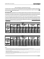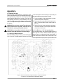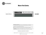
1
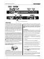
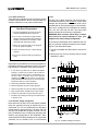
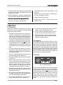
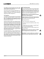
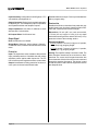
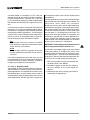
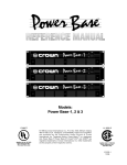
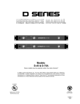
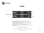
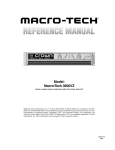
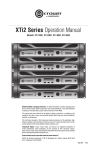
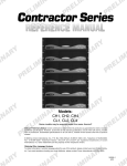
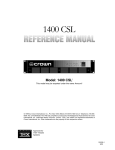
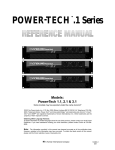
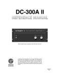
D SEries
30
50
HEADPHONES
CHANNEL 1
20
40
0
OFF
IOC
SIGNAL
ON
20
40
50
10
LEVEL
30
CHANNEL 2
10
LEVEL
0
POWER
Models:
D-45 & D-75A
Some models may be exported under the name Amcron.®
©1999 by Crown International, Inc., P.O. Box 1000, Elkhart, Indiana 46515-1000 U.S.A. Telephone:
219-294-8000. D Series amplifiers are produced by the Professional Audio Division of Crown
International, Inc. Trademark Notice: Amcron,® Crown® and IOC ® are registered trademarks of Crown
International, Inc. Other trademarks are the property of their respective owners.
Printed on
recycled paper.
125243-3
8/99
3
YEAR
THREE YEAR
FULL WARRANTY
3
YEAR
WORLDWIDE
NORTH AMERICA
SUMMARY OF WARRANTY
The Crown Audio Division of Crown International, Inc., 1718 West
Mishawaka Road, Elkhart, Indiana 46517-4095 U.S.A. warrants to you,
the ORIGINAL PURCHASER and ANY SUBSEQUENT OWNER of each
NEW Crown1 product, for a period of three (3) years from the date of
purchase by the original purchaser (the “warranty period”) that the new
Crown product is free of defects in materials and workmanship, and we
further warrant the new Crown product regardless of the reason for failure,
except as excluded in this Crown Warranty.
SUMMARY OF WARRANTY
The Crown Audio Division of Crown International, Inc., 1718 West Mishawaka
Road, Elkhart, Indiana 46517-4095 U.S.A. warrants to you, the ORIGINAL
PURCHASER and ANY SUBSEQUENT OWNER of each NEW Crown product, for a period of three (3) years from the date of purchase by the original
purchaser (the “warranty period”) that the new Crown product is free of defects
in materials and workmanship. We further warrant the new Crown product
regardless of the reason for failure, except as excluded in this Warranty.
1
Note: If your unit bears the name “Amcron,” please substitute it for the
name “Crown” in this warranty.
ITEMS EXCLUDED FROM THIS CROWN WARRANTY
This Crown Warranty is in effect only for failure of a new Crown product
which occurred within the Warranty Period. It does not cover any product
which has been damaged because of any intentional misuse, accident,
negligence, or loss which is covered under any of your insurance
contracts. This Crown Warranty also does not extend to the new Crown
product if the serial number has been defaced, altered, or removed.
ITEMS EXCLUDED FROM THIS CROWN WARRANTY
This Crown Warranty is in effect only for failure of a new Crown product which
occurred within the Warranty Period. It does not cover any product which has
been damaged because of any intentional misuse, accident, negligence, or loss
which is covered under any of your insurance contracts. This Crown Warranty
also does not extend to the new Crown product if the serial number has been
defaced, altered, or removed.
WHAT THE WARRANTOR WILL DO
We will remedy any defect, regardless of the reason for failure (except as
excluded), by repair, replacement, or refund. We may not elect refund
unless you agree, or unless we are unable to provide replacement, and
repair is not practical or cannot be timely made. If a refund is elected, then
you must make the defective or malfunctioning product available to us free
and clear of all liens or other encumbrances. The refund will be equal to
the actual purchase price, not including interest, insurance, closing costs,
and other finance charges less a reasonable depreciation on the product
from the date of original purchase. Warranty work can only be performed
at our authorized service centers. We will remedy the defect and ship the
product from the service center within a reasonable time after receipt of
the defective product at our authorized service center.
WHAT THE WARRANTOR WILL DO
We will remedy any defect, regardless of the reason for failure (except as
excluded), by repair, replacement, or refund. We may not elect refund unless
you agree, or unless we are unable to provide replacement, and repair is not
practical or cannot be timely made. If a refund is elected, then you must make
the defective or malfunctioning product available to us free and clear of all liens
or other encumbrances. The refund will be equal to the actual purchase price,
not including interest, insurance, closing costs, and other finance charges less
a reasonable depreciation on the product from the date of original purchase.
Warranty work can only be performed at our authorized service centers or at
the factory. We will remedy the defect and ship the product from the service
center or our factory within a reasonable time after receipt of the defective
product at our authorized service center or our factory. All expenses in
remedying the defect, including surface shipping costs in the United States, will
be borne by us. (You must bear the expense of shipping the product between
any foreign country and the port of entry in the United States and all taxes,
duties, and other customs fees for such foreign shipments.)
HOW TO OBTAIN WARRANTY SERVICE
You must notify us of your need for warranty service not later than ninety
(90) days after expiration of the warranty period. All components must be
shipped in a factory pack. Corrective action will be taken within a
reasonable time of the date of receipt of the defective product by our
authorized service center. If the repairs made by our authorized service
center are not satisfactory, notify our authorized service center
immediately.
HOW TO OBTAIN WARRANTY SERVICE
You must notify us of your need for warranty service not later than ninety (90)
days after expiration of the warranty period. All components must be shipped
in a factory pack, which, if needed, may be obtained from us free of charge.
Corrective action will be taken within a reasonable time of the date of receipt of
the defective product by us or our authorized service center. If the repairs made
by us or our authorized service center are not satisfactory, notify us or our
authorized service center immediately.
DISCLAIMER OF CONSEQUENTIAL AND INCIDENTAL DAMAGES
YOU ARE NOT ENTITLED TO RECOVER FROM US ANY INCIDENTAL
DAMAGES RESULTING FROM ANY DEFECT IN THE NEW CROWN
PRODUCT. THIS INCLUDES ANY DAMAGE TO ANOTHER PRODUCT
OR PRODUCTS RESULTING FROM SUCH A DEFECT.
DISCLAIMER OF CONSEQUENTIAL AND INCIDENTAL DAMAGES
YOU ARE NOT ENTITLED TO RECOVER FROM US ANY INCIDENTAL
DAMAGES RESULTING FROM ANY DEFECT IN THE NEW CROWN
PRODUCT. THIS INCLUDES ANY DAMAGE TO ANOTHER PRODUCT OR
PRODUCTS RESULTING FROM SUCH A DEFECT. SOME STATES DO
NOT ALLOW THE EXCLUSION OR LIMITATIONS OF INCIDENTAL OR
CONSEQUENTIAL DAMAGES, SO THE ABOVE LIMITATION OR
EXCLUSION MAY NOT APPLY TO YOU.
WARRANTY ALTERATIONS
No person has the authority to enlarge, amend, or modify this Crown
Warranty. This Crown Warranty is not extended by the length of time
which you are deprived of the use of the new Crown product. Repairs and
replacement parts provided under the terms of this Crown Warranty shall
carry only the unexpired portion of this Crown Warranty.
DESIGN CHANGES
We reserve the right to change the design of any product from time to time
without notice and with no obligation to make corresponding changes in
products previously manufactured.
LEGAL REMEDIES OF PURCHASER
No action to enforce this Crown Warranty shall be commenced later than
ninety (90) days after expiration of the warranty period.
THIS STATEMENT OF WARRANTY SUPERSEDES ANY OTHERS
CONTAINED IN THIS MANUAL FOR CROWN PRODUCTS.
9/90
WARRANTY ALTERATIONS
No person has the authority to enlarge, amend, or modify this Crown Warranty.
This Crown Warranty is not extended by the length of time which you are
deprived of the use of the new Crown product. Repairs and replacement parts
provided under the terms of this Crown Warranty shall carry only the unexpired
portion of this Crown Warranty.
DESIGN CHANGES
We reserve the right to change the design of any product from time to time
without notice and with no obligation to make corresponding changes in
products previously manufactured.
LEGAL REMEDIES OF PURCHASER
THIS CROWN WARRANTY GIVES YOU SPECIFIC LEGAL RIGHTS, YOU
MAY ALSO HAVE OTHER RIGHTS WHICH VARY FROM STATE TO STATE.
No action to enforce this Crown Warranty shall be commenced later than ninety
(90) days after expiration of the warranty period.
THIS STATEMENT OF WARRANTY SUPERSEDES ANY OTHERS
CONTAINED IN THIS MANUAL FOR CROWN PRODUCTS.
Telephone: 219-294-8200. Facsimile: 219-294-8301
Telephone: 219-294-8200. Facsimile: 219-294-8301
9/90
The information furnished in this manual does not include all of the details of design, production, or variations of the
equipment. Nor does it cover every possible situation which may arise during installation, operation or maintenance. If you need special assistance beyond the scope of this manual, please contact our Technical Support
Group.
Crown Audio Division Technical Support Group
Plant 2 SW, 1718 W. Mishawaka Rd., Elkhart, Indiana 46517 U.S.A.
Phone: 800-342-6939 (North America, Puerto Rico and Virgin Islands) or 219-294-8200
Fax: 219-294-8301 Fax Back (North America only): 800-294-4094 or 219-293-9200
Fax Back (International): 219-294-8100 Internet: http://www.crownaudio.com
CAUTION
AVIS
RISK OF ELECTRIC SHOCK
DO NOT OPEN
RISQUE DE CHOC ÉLECTRIQUE
N’OUVREZ PAS
TO PREVENT ELECTRIC SHOCK DO
NOT REMOVE TOP OR BOTTOM
COVERS. NO USER SERVICEABLE
PARTS INSIDE. REFER SERVICING
TO QUALIFIED SERVICE PERSONNEL. DISCONNECT POWER CORD
BEFORE REMOVING BACK PANEL
COVER TO ACCESS GAIN SWITCH.
À PRÉVENIR LE CHOC ÉLECTRIQUE
N’ENLEVEZ PAS LES COUVERCLES. IL
N’Y A PAS DES PARTIES SERVICEABLE
À L’INTÉRIEUR. TOUS REPARATIONS
DOIT ETRE FAIRE PAR PERSONNEL
QUALIFIÉ SEULMENT. DÉBRANCHER
LA BORNE AVANT D’ENLEVER LA
COVERTURE EN ARRIÈRE.
Magnetic Field
WARNING
TO REDUCE THE RISK OF ELECTRIC
SHOCK, DO NOT EXPOSE THIS
EQUIPMENT TO RAIN OR MOISTURE!
The lightning bolt
triangle is used to
alert the user to the
risk of electric shock.
CAUTION! Do not locate sensitive high-gain equipment such as preamplifiers or tape decks directly
above or below the unit. Because this amplifier has
a high power density, it has a strong magnetic field
which can induce hum into unshielded devices that
are located nearby. The field is strongest just above
and below the unit.
If an equipment rack is used, we recommend locating the amplifier(s) in the bottom of the rack and the
preamplifier or other sensitive equipment at the top.
The exclamation point
triangle is used to alert the
user to important operating
or maintenance instructions.
D-45 / D-75A Power Amplifiers
Important Safety Instructions
1) Read these instructions.
2) Keep these instructions.
3) Heed all warnings.
4) Follow all instructions.
5) Do not use this apparatus near water.
6) Clean only with a dry cloth.
7) Do not block any ventilation openings. Install in accordance with the
manufacturer’s instructions.
8) Do not install near any heat sources such as radiators, heat registers, stoves,
or other apparatus that produce heat.
9) Do not defeat the safety purpose of the polarized or grounding-type plug. A
polarized plug has two blades with one wider than the other. A groundingtype plug has two blades and a third grounding prong. The wide blade or the
third prong is provided for your safety. If the provided plug does not fit into
your outlet, consult an electrician for replacement of the obsolete outlet.
10) Protect the power cord from being walked on or pinched, particularly at
plugs, convenience receptacles, and the point where they exit from the apparatus.
11) Only use attachments/accessories specified by the manufacturer.
12) Unplug this apparatus during lightning storms or when unused for long periods of time.
13) Refer all servicing to qualified service personnel. Servicing is required when
the apparatus has been damaged in any way, such as power-supply cord or
plug is damaged, liquid has been spilled or objects have fallen into the apparatus, the apparatus has been exposed to rain or moisture, does not operate
normally, or has been dropped.
Page 4
D-45 / D-75A Power Amplifiers
Fig. 1.1 Front and Back Views
1 Welcome
Reliability is the first thing you get with your purchase of
a Crown power amplifier. The D-45 and D-75A both deliver dependable operation with a wide variety of loads.
Because of their exceptional reliability, these amplifiers
have become the leading choice of professionals for
use in recording studios, laboratories and public facilities. You can even find them on the road. Their sonic
excellence also makes them a very good choice for
your personal listening pleasure.
The D-45 and D-75A amplifiers are compact and provide ultra-low distortion for medium power applications.
Crown’s advanced AB+B circuitry ensures efficient operation and protects against shorted, open, mismatched or low-impedance loads that can affect any
amplifier’s performance. Crown further protects your investment with the industry’s only three year “No-Fault”
full warranty. After learning about your amplifier’s features, facilities and capabilities, you’ll understand why
Crown power amplifiers have long been recognized as
the worldwide standard for audio excellence.
For your protection, please send in your warranty registration card today and save your bill of sale as it is your
official proof of purchase.
shipping damage. Even if the unit arrived in perfect
condition, as most do, save all packing materials so
you will have them if you ever need to transport the unit.
NEVER SHIP THE UNIT WITHOUT THE FACTORY
PACK.
1.2 Features
Your dual-channel (stereo) amplifier can optionally be
configured to deliver double the power from a single
(mono) channel. It also provides the following features:
❏ Powerful AB+B class circuitry yields maximum efficiency
with minimum crossover “notch” distortion.
❏ IOC ® (Input/Output Comparator) alerts of any distortion
that exceeds 0.05% to provide proof of distortion-free
performance.
❏ Signal presence indicators verify the presence of amplifier output.
❏ Detented level controls for precise repeatability.
❏ Ultra-low harmonic and intermodulation distortion result
in the best dynamic transfer function in the industry.
❏ Very low noise and wide dynamic range exceed the audio specifications for digital compact discs (CDs).
❏ High damping factor provides exceptional loudspeaker
motion control.
1.1 Unpacking
Please unpack and inspect your new amplifier for any
damage that may have occurred during transit. If damage is found, notify the transportation company immediately. Only you, the consignee, may initiate a claim for
❏ Convection cooling system dissipates heat through the
heat sinks and chassis for optimal cooling and maintenance-free operation.
❏ Mounts in a standard 19-inch (48.3-cm) rack.
❏ Three year “No-Fault” full warranty protects your investment and guarantees the specifications of units in North
America and other select countries.
Page 5
D-45 / D-75A Power Amplifiers
2 Installation
D-45 and D-75A amplifiers are designed for standard
19 inch (48.3 cm) rack mounting, or they can be
stacked without a cabinet. Before mounting your amplifier, determine whether you need to change the
amplifier’s internal settings for your application.
tors are located on the back panel. If you are making
changes to a unit that is already installed, make sure
the power is disconnected and the level controls are
turned down. Following these precautions will reduce
the chance of loud blasts and loudspeaker damage.
The amplifier’s internal settings make it possible for you
to operate the unit in bridge-mono mode and to change
the unit’s input sensitivity to 0.775 volts. If you need
maximum power from a single channel, you will probably want to use the bridge-mono mode. In contrast,
few applications will require you to change the input
sensitivity. If you need to configure the amplifier for
bridge-mono mode, or if you want more specific information on your amplifier’s input sensitivity, please refer
to Appendix A before proceeding.
Please use care when making connections, selecting
signal sources and controlling the output level. The load
you save may be your own! Crown is not liable for damage to other system components due to careless amplifier use or overpowering.
2.1 Mounting
Your amplifier should be mounted in a standard 19 inch
(48.3 cm) equipment rack. It occupies only 1.75 inches
(4.45 cm) of vertical rack space. Mounting screws and
washers are provided with the amplifier. Although units
can be stacked, this practice is not recommended. Instead, mount multiple units in a rack leaving air space
between them. Also, before mounting the amplifier,
please read about the amplifier’s cooling requirements
in the section that follows.
CAUTION: Be careful using headphones. Too much
power can cause permanent hearing loss.
2.3.1 Mode of Operation
Your amplifier may be operated in either dual or bridgemono mode. Configuration of the dual/mono jumper is
described in Appendix A. Dual and bridge-mono
modes have important wiring differences, so be sure to
note the requirements for the mode you select.
DUAL
Dual mode installation is very intuitive. The channel 1
input feeds the channel 1 output, and the channel 2
input feeds the channel 2 output. Use two-conductor
cable to connect loudspeakers to the amplifier’s output
terminals. Be careful not to short the outputs together,
and observe correct loudspeaker polarity.
CAUTION: Do not tie the two outputs together. Never
tie an output to another amplifier’s output.
Fig. 2.1 Mounting Dimensions
2.2 Cooling
Your amplifier does not have a cooling fan. To prevent
overheating, sufficient ventilation is required. Equipment
racks or cabinets should have perforated top and bottom panels. This is very important if more than one unit
will be mounted in a rack. We recommend allowing a
1.75 inch (4.45 cm) space above and below the unit if it
will be operated continuously at high output levels.
2.3 Wiring
Figure 2.2 shows two of the most common ways to install your amplifier in a sound system. Except for the
stereo headphone jack, all input and output connecPage 6
MONO
Installation in bridge-mono mode is very different from
dual mode. First, only the channel 1 input should be
used. Do not use the channel 2 input. For best results,
disconnect all input sources to channel 2 and turn off
the channel 2 level control (fully counterclockwise).
Note: The channel 2 input and level control are not defeated in bridge-mono mode. A signal feeding channel
2 will work against the signal feeding channel 1.
Connect loudspeaker cables to the positive (+) output
terminals as shown in Figure 2.2 in the bottom illustration. Do not use or short the negative (–) terminals. The
bridge-mono output is balanced, and should remain
isolated from the chassis and input signal grounds.
CAUTION: Only connect balanced loads to a bridgemono output. Output lines must be isolated from
ground or severe oscillations may occur.
If your loudspeakers don’t need the additional voltage,
and you only have one input signal to drive multiple
D-45 / D-75A Power Amplifiers
Fig. 2.2 System Connection
loudspeakers, you can use bridge-mono mode without
actually bridging the outputs. Bridge-mono mode is like
dual mode except the channel 1 input feeds both outputs, and the channel 2 output is inverted. To use
bridge-mono mode without bridging the outputs, wire
your loudspeakers as you would for dual mode, but
invert the polarity of the channel 2 output wiring (positive goes to negative, and negative goes to positive).
2.3.2 Input Connection
The balanced combination XLR/phone inputs have a
typical impedance of 20 K ohms. With unbalanced wiring, input impedance is typically 10 K ohms. The line
level output from most devices is sufficient to drive the
inputs. The XLR connectors are wired with pin 1 as
ground, pin 2 as positive (+) and pin 3 as negative (–);
the phone connectors are wired with tip as positive (+),
ring as negative (–) and sleeve as ground. Be sure to
use shielded cables with unbalanced sources.
Input Wiring Tips
1. Use only shielded cable.
2. Avoid unbalanced lines longer than
10 feet (3 meters).
3. Keep signal and power wiring apart.
4. Turn off the unit before making connections. Crown is not liable for injury or
damage due to overdriven components.
CAUTION: Never connect input and output grounds
together.
Page 7
D-45 / D-75A Power Amplifiers
2.3.3 Output Connection
There are many methods that can be used to prevent
potential output problems, but the most important preventative measure is to use good common sense.
Use Good Connectors
1. To prevent possible short circuits, do not expose the loudspeaker cable connectors.
2. Do not use connectors that might accidentally tie conductors together when making or
breaking connections (for example, a standard three-wire stereo phone plug).
3. Never use connectors that can be plugged
into an AC power receptacle.
codes.
120 VAC, 60 Hz North American units do not have a
convertible transformer, and cannot be used at other
voltages and frequencies. International units can be
operated with an AC mains frequency of 50 to 400 Hz,
and can be configured for five different line voltages:
100, 120, 200, 220 and 240 VAC. The back panel
sticker indicates the unit’s factory configuration.
WARNING: Risk of electric shock! Only a competent technician should attempt to alter your
amplifier’s AC mains voltage configuration.
To operate an international unit at a different line voltage, you will need a phillips screwdriver and a soldering iron. Then follow these steps:
4. Avoid connectors with low current-carrying
capacity.
1. Turn off the amplifier and disconnect it from the AC
mains.
5. Do not use connectors with any tendency to
short.
2. Remove the top cover by removing the six screws
that hold it in place.
High-frequency oscillations can cause your amplifier to
prematurely activate its protection circuitry. To prevent
high-frequency oscillations, follow these guidelines:
1. If you have long cable runs or different amplifiers
sharing a common tray or jacket, use tie-wraps to
bundle together loose pairs of loudspeaker conductors. (Do not bundle wires from different
amplifiers.) This reduces the chance of conductors
acting like antennas to transmit or receive the high
frequencies that can cause oscillation.
2. Avoid using shielded loudspeaker cable.
3. Never tie together input and output grounds.
4. Never tie together the output of different amplifiers.
5. Keep output cables separated from input cables.
6. Install a low-pass filter in series with each input.
7. Install the input wiring according to the instructions
in Section 2.3.2.
2.3.4 AC Mains Voltage Configuration
North American 120 VAC, 60 Hz units have a standard
three wire, grounded AC plug as specified by UL requirements. The 120 volt models and the European
models have the appropriate plug. The other 200, 220
and 240 volt models have a North American 120 volt
plug. The installer must cut off the plug and supply and
install a plug appropriate for the installation. Note:
Crown assumes no liability whatsoever for ungrounded
operation, nor for violation of UL or local electrical
Page 8
Fig. 2.3 AC Mains Voltage Conversion
D-45 / D-75A Power Amplifiers
3. With the unit’s top side up and the front panel toward
you, locate the terminal strip toward the front of the
amplifier on your right.
4. Using a soldering iron, change the appropriate jumpers for the desired operating voltage (see Figure 2.3).
e to only install the appr
opriate fuse:
5. Be sur
sure
appropriate
100 or 120 volt mains: 2 Amp type 3AG.
North American 200, 220 and 240 volt mains: 1 Amp
type 3AG.
European 220 or 240 volt mains: 1 Amp IEC type T,
time lag, low breaking capacity.
6. Carefully check all connections.
7. Repeat steps 1 and 2 in reverse order to reassemble the unit.
3 Operation
3.1 Precautions
Although your amplifier is well-protected from any external faults, we recommend that you take the following
precautions for safe operation:
1. When the level of an input source is uncertain, or
an audio component has not previously been
used with your amplifier, always begin with the
level controls at a minimum and gradually increase them while monitoring the output level.
This helps to avoid possible loudspeaker blasts.
2. Don’t forget, your amplifier does not have a turnon delay. Beware of turn-on transients from other
equipment ahead of the amplifier—always turn
the amplifier on after other equipment has stabilized.
10. Never short an output ground lead to the input
signal ground or oscillations may result.
11. The D-45 and D-75A amplifiers are not recommended for use at frequencies above 30 kHz.
12. Tampering with the circuitry or making unauthorized circuit changes may be hazardous and invalidates all agency listings.
3.2 Indicators
3. Turn off the amplifier and unplug it from the AC
mains before replacing the fuse, installing an input sensitivity jumper or changing the position of
the dual/mono jumper.
Your amplifier has five front panel indicators. First, a
power indicator behind the front panel becomes visible
when the unit is turned on and has power. A signal indicator for each channel flashes when there is output from
the amplifier. The IOC (Input/Output Comparator) indicators work like sensitive distortion meters and flash
when the amplifier causes any distortion of 0.05% or
more. The IOC indicators typically glow for about one
minute after the AC power is turned off.
4. There are important differences between dual
and mono wiring. Refer to Section 2.3.
3.3 Controls
5. Operate the amplifier with the correct fuse. Refer
to Section 3.5.
6. When driving transformer-coupled devices
(such as electrostatic loudspeakers) or other
loads of less than 3 ohms, install an isolating capacitor in series with the positive (+) output.
Such operation may damage the load and
needlessly activate the amplifier’s V-I limiting.
7. Operate the amplifier with AC mains of no more
than 10% above the rated line voltage and at the
specified line frequency.
8. Never connect the output to a power supply output, battery or power main. This can cause electric shock and damage to the amplifier.
9. Do not expose the amplifier to corrosive chemicals such as soft drinks, lye, salt water, etc.
Fig. 3.1 Visible Indicators
A power switch and detented level controls are located
on the front panel. When you power up the amplifier,
remember that the unit does not have a turn-on delay.
Each channel has its own level control which is used to
adjust the desired output level. Both level controls are
used in dual mode, but only the channel 1 control
should be used in bridge-mono mode. Channel 2 control should be fully counter-clockwise in bridge-mono
mode.
Page 9
D-45 / D-75A Power Amplifiers
The amplifier is switched between dual and bridgemono operation with the dual/mono jumper located inside the amplifier (see Appendix A).
3.5 Fuse Replacement
The unit’s input gain is 26 dB as determined by 1%
precision resistors in the feedback loop. This can be
changed to a sensitivity of 0.775 volts by following the
instructions provided in Appendix A.
The AC mains fuse is located on the back panel beside
the power cord. This fuse will not blow unless something is wrong. Before replacing the unit’s fuse, you
should be sure to fix the source of the problem. If the
problem is not immediately apparent, the unit probably
needs to be serviced by a qualified technician.
3.4 Protection
WARNING: Always unplug the amplifier from the AC
mains before removing the fuse.
Your amplifier is protected against all common hazards
that plague high-power amplifiers, including shorted,
open or mismatched loads; overloaded power supplies, chain destruction phenomena, input overload
and high-frequency blowups.
Protection against shorted and mismatched loads is
provided by an instantaneous limiter that automatically
limits current to the maximum safe value for the output
transistors. With a loudspeaker, you can tell the amplifier has activated load protection because it causes
audible distortion. The noise might be compared to
crossover notch distortion or a snapping sound, depending on the load characteristics. Loudspeaker systems with impedances of 4 ohms or higher should not
activate the protection system.
All voltage amplification circuitry is designed to limit
current. So in the extremely unlikely event of a device
failure, the amplifier will prevent further damage. The
input stages are protected from overload damage by
series resistors. The unit also features a controlled slew
rate and a V-I limiter that protect the amplifier from highfrequency (RF) blowups.
Page 10
To replace the fuse, turn off the power switch and disconnect the power plug from the AC mains. Unscrew
the fuse holder cap and remove the fuse.
Install appropriate fuse:
100 or 120 volt mains: 2 Amp type 3AG.
North American 200, 220 and 240 volt mains: 1 Amp
type 3AG.
European 220 or 240 volt mains: 1 Amp IEC type T,
time lag, low breaking capacity.
Then, simply resecure the fuse holder cap and reconnect the AC mains.
IMPORTANT: Never install a fuse that has a higher
current rating than the recommended value.
IMPORTANT: The 3AG and IEC fuses are different
physical sizes and require different holder caps.
D-45 / D-75A Power Amplifiers
4 Specifications
Note: The following specifications apply to all units in dual
mode with both channels driven into 8 ohm loads and an
input sensitivity of 26 dB gain unless otherwise specified.
Standard 1 kHz Power: This term refers to maximum average power in watts at 1 kHz with 0.1% THD.
Full Bandwidth FTC Power: This term refers to standard FTC
power in watts from 20 Hz to 20 kHz with 0.1% THD.
120 VAC, 60 Hz Units: These North American units have
dedicated transformers for 120 VAC, 60 Hz power mains.
Bridge-Mono mode:
70 watts into 8 ohms.
50 watts into 16 ohms.
D-75A:
Dual mode (both channels driven):
55 watts into 4 ohms.
40 watts into 8 ohms.
25 watts into 16 ohms.
Bridge-Mono mode:
110 watts into 8 ohms.
80 watts into 16 ohms.
International Units: These units have a convertible transformer for 100, 120, 200, 220 and 240 VAC, 50 to 400 Hz
power mains.
Load Impedance: Safe with all types of loads. Rated
for 4 to 16 ohms in dual mode, and 8 to 16 ohms in
bridge-mono mode.
Performance
Required AC Mains: 100, 120, 200, 220 and 240 VAC
(±10%), 50 to 400 Hz for international units (depending
on the transformer configuration). North American
120 VAC, 60 Hz units are not convertible and can only
be used at the specified voltage and frequency. All units
draw 15 watts or less when idle. Maximum AC power
consumption is 150 watts.
Frequency Response: ±0.1 dB from 20 Hz to 20 kHz
at 1 watt.
Phase Response: +10 to –15 degrees from 20 Hz to
20 kHz at 1 watt.
Signal-to-Noise: 106 dB from 20 Hz to 20 kHz at full
bandwidth FTC power.
Total Harmonic Distortion (THD): Less than 0.001%
at full bandwidth FTC power from 20 Hz to 400 Hz increasing linearly to 0.05% at 20 kHz.
Intermodulation Distortion (IMD): (60 Hz and 7 kHz
4:1) Less than 0.01% from 0.25 watts to full bandwidth
FTC power, and less than 0.05% from 0.01 to 0.25 watts.
Crosstalk: Greater than 100 dB below full bandwidth
FTC power from 100 Hz to 1 kHz decreasing linearly to
80 dB at 20 kHz.
Damping Factor: Greater than 400 from DC to 400 Hz.
Controlled Slew Rate: 6 volts per ms. (Slew rates are
limited to useful levels for ultrasonic/RF protection.)
Voltage Gain: (At the maximum level setting) 20.6:1
±3% or 26.3 dB ±0.3 dB. Refer to Appendix A for information on the 0.775 volt sensitivity setting.
Power
Output Power:
Note: Maximum average power per channel at 1 kHz
with 0.1% or less THD.
D-45:
Dual mode (both channels driven):
35 watts into 4 ohms.
25 watts into 8 ohms.
20 watts into 16 ohms.
Controls
Power: A two-position front panel rotary on/off switch.
Level: An independent 31-position detented front panel
level control for each channel.
Dual/Mono: The dual/mono jumper is located inside
the amplifier (refer to Appendix A).
Ground Lift: To prevent ground loops, the chassis and
signal grounds are separated (or “lifted”) by a permanent impedance installed between them. There is no
control for this feature.
Indicators
Signal Presence: The green front panel indicator for
each channel flashes synchronously with the channel’s
output signal to indicate its presence.
Input/Output Comparator: The red Input/Output Comparator (IOC ) indicator for each channel flashes if any
type of distortion reaches 0.05%.
Input/Output
Input Connector: A balanced 3-pin female Neutrik®
combination XLR and ¼-inch phone connector for each
channel.
Input Impedance: Nominally 20 K ohms, balanced.
Nominally 10 K ohms, unbalanced.
Page 11
D-45 / D-75A Power Amplifiers
Input Sensitivity: Configurable for 26 dB gain or 0.775
volt sensitivity (see Appendix A).
Turn-On: Minimum thumps. Power-up is instantaneous
with no program delay.
Output Connector: Barrier block terminals and stereo
headphone jack. The headphone output is unpadded,
and in parallel with the main amplifier outputs.
Construction
Output Impedance: Less than 15 milliohms in series
with less than 3 microhenries.
DC Output Offset: 10 millivolts or less.
Output Signal
Dual: Unbalanced, two channel.
Bridge-Mono: Balanced, single channel. Channel 1
controls are active; channel 2 controls should be turned
down.
Protection
Input: The inputs have series resistance that provides
input overload protection. Controlled slew rate voltage
amplifiers protect against radio frequencies. The AC
line is fused to protect against excessive current draw.
Output: Instantaneous limiting protection for short circuits, open circuits and mismatched loads.
Page 12
Durable black finish on aluminum front panel with gray
suede Lexan insert. Aluminum chassis provides maximum heat conduction and minimum weight.
Dimensions: 19 inch (48.3 cm) rack mount width,
1.75 inch (4.5 cm) height, 8.5 inch (21.6 cm) depth
behind the mounting surface, and a 0.625 inch (1.6 cm)
protrusion in front of the mounting surface
Approximate Weight:
D-45: 8 pounds, 11 ounces (3.9 kg) net; 10 pounds,
9 ounces (4.8 kg) shipping weight.
D-75A: 9 pounds, 7 ounces (4.3 kg) net; 11 pounds,
4 ounces (5.1 kg) shipping weight.
Cooling: The amplifier is totally convection cooled. The
entire aluminum chassis acts as a conductor to dissipate heat. The covers and front panel extrusion also
act as heat sinks. Much of the unit’s heat is conducted
through the extruded front panel. This design is used
so that front panel contact with the equipment rack will
also dissipate heat.
D-45 / D-75A Power Amplifiers
Crown specifications are guaranteed for three years.
In an effort to provide you with as much information as possible about the power-producing capabilities of your amplifier, we have created the
following power matrix. The specifications found in these tables are for 120 VAC, 60 Hz North American units and are guaranteed for three
years. Some spaces in the matrix are left blank because we do not provide this same guarantee for those conditions—however, your amplifier
will perform well under all conditions listed in the table.
Power Specifications
When measuring power, 0.1% THD appears to be the industry standard for distortion. The maximum average power shown in the power
matrix is measured when THD rises to 0.1% so you can easily compare Crown specifications to those of other manufacturers. But this high
level of distortion actually allows for some clipping which is undesirable. The burst power specifications in the power matrix are measured at
0.05% THD which is not a clipped condition. Crown has chosen to provide these specifications with the hope that other manufacturers will
also start providing specifications that correspond to the way amplifiers should be used in the real world—without clipped output.
Many manufacturers publish power specifications with a tolerance of ±1 dB or worse. That means their amplifier can deviate more than 20%
in output! A 100 watt amplifier would meet their specification if it only produced 79.4 watts. Other manufacturers qualify their specs by saying
they are “typical,” “subject to manufacturing tolerances,” “single channel driven” or that they are specified with “fuses bypassed.” Each of these
statements effectively removes any performance guarantee. We take a different approach at Crown—our published specifications are guaranteed for three years. Further, because our “in-house” specs are more stringent than our published specs, every Crown amplifier will exceed
its published specs. We believe you should get what you pay for.
Fig. 4.1 D-45 Power Matrix
Fig. 4.2 D-75A Power Matrix
Notes:
All power matrix specifications are based on a 0.1% regulated 120 VAC, 60 Hz power mains and an ambient room temperature of 70° F (21° C).
1. Continuous power in the context of Federal Trade Commission testing is understood to be a minimum of five minutes of operation. Harmonic distortion is measured at the RMS
sum total as a percentage of the fundamental output voltage. This applies for all wattages greater than 0.25 watts.
2. A 1 kHz sine wave is presented to the amplifier and the output monitored for nonlinear distortion. The level is increased until the THD reaches 0.1%. At this level the average
power per channel is reported.
3. A single cycle sine wave is presented to the amplifier and monitored for nonlinear distortion. The average power during the burst is reported. Loudspeakers must be able to
withstand this level if they are to be safely used with this amplifier.
4. A 40 millisecond burst or a two cycle sine wave (whichever is of greater duration) is used and the power computed as the average power during the burst. The duty cycle of
this test is 10 percent. This power level is a measure of how loud an amplifier is as perceived by the human ear.
5. EIA standard RS-490 (both channels driven).
Page 13
D-45 / D-75A Power Amplifiers
6 Service
This unit has very sophisticated circuitry which should
only be serviced by a fully trained technician. This is
one reason why each unit bears the following label:
Your repaired unit will be returned via UPS ground.
Please contact us if other arrangements are required.
CAUTION: To prevent electric shock, do not remove
covers. No user serviceable parts inside. Refer servicing to a qualified technician.
6.1 Worldwide Service
Service may be obtained from an authorized service
center. (Contact your local Crown/Amcron representative or our office for a list of authorized service centers.)
To obtain service, simply present the bill of sale as proof
of purchase along with the defective unit to an authorized service center. They will handle the necessary
paperwork and repair.
Remember to transport your unit in the original factory
pack.
6.2 North American Service
Service may be obtained in one of two ways: from an
authorized service center or from the factory. You may
choose either. It is important that you have your copy of
the bill of sale as your proof of purchase.
6.2.1 Service at a North American Service Center
This method usually saves the most time and effort.
Simply present your bill of sale along with the defective
unit to an authorized service center to obtain service.
They will handle the necessary paperwork and repair.
Remember to transport the unit in the original factory
pack. A list of authorized service centers in your area
can be obtained from our Technical Support Group.
6.2.2 Factory Service
To obtain factory service, fill out the service information page found in the back of this manual and send it
along with your proof of purchase and the defective
unit to the Crown factory.
For warranty service, we will pay for ground shipping
both ways in the United States. Contact Crown Factory
Service or Technical Support to obtain prepaid shipping labels prior to sending the unit. Or, if you prefer,
you may prepay the cost of shipping, and Crown will
reimburse you. Send copies of the shipping receipts to
Crown to receive reimbursement.
Page 14
Always use the
original factory pack
to transport the unit.
Factory Service Shipping Instructions:
1. When sending a Crown product to the factory for
service, be sure to fill out the service information
form that follows and enclose it inside your unit’s
shipping pack. Do not send the service information form separately.
2. To ensure the safe transportation of your unit to
the factory, ship it in an original factory packing
container. If you don’t have one, call or write
Crown’s Parts Department. With the exception of
polyurethane or wooden crates, any other packing material will not be sufficient to withstand the
stress of shipping. Do not use loose, small size
packing materials.
3. Do not ship the unit in any kind of cabinet (wood
or metal). Ignoring this warning may result in extensive damage to the unit and the cabinet. Accessories are not needed—do not send the
instruction manual, cables and other hardware.
If you have any questions, please call or write the Crown
Technical Support Group.
Crown Audio Division
Technical Support / Factory Service
Plant 2 SW, 1718 W. Mishawaka Rd., Elkhart,
Indiana 46517 U.S.A.
Telephone: 219-294-8200
800-342-6939 (North America,
Puerto Rico, and Virgin Islands only)
Facsimile: 219-294-8301 (Technical Support)
219-294-8124 (Factory Service)
Fax Back:
Internet:
219-293-9200 (North America only)
800-294-4094 (North America only)
219-294-8100 (International)
http://www.crownaudio.com
D-45 / D-75A Power Amplifiers
Crown Factory Service Information
Shipping Address: Crown International, Inc., Factory Service, Plant 2 SW, 1718 W. Mishawaka Rd., Elkhart, IN 46517
Phone: 1-800-342-6939 or 1-219-294-8200 Fax: 1-219-294-8124
Owner’s Name: _________________________________________________________________________
Shipping Address: ______________________________________________________________________
Phone Number: _____________________________
Fax Number: _____________________________
Model: ________________________ Serial Number: ______________ Purchase Date: ___________
NATURE OF PROBLEM
(Be sure to describe the conditions that existed when the problem occurred and what attempts were made to correct it.)
______________________________________________________________________________
______________________________________________________________________________
______________________________________________________________________________
______________________________________________________________________________
______________________________________________________________________________
Detach and send with unit.
______________________________________________________________________________
______________________________________________________________________________
______________________________________________________________________________
______________________________________________________________________________
______________________________________________________________________________
______________________________________________________________________________
______________________________________________________________________________
______________________________________________________________________________
______________________________________________________________________________
______________________________________________________________________________
Other equipment in your system: _________________________________________________________
______________________________________________________________________________
______________________________________________________________________________
______________________________________________________________________________
______________________________________________________________________________
______________________________________________________________________________
______________________________________________________________________________
If warranty has expired, payment will be: ❏ Cash/Check
❏ VISA
❏ MasterCard
❏ C.O.D.
Card Number:___________________________ Exp. Date:_______ Signature:____________________________
ENCLOSE THIS PORTION WITH THE UNIT. DO NOT MAIL SEPARATELY.
Page 15
D-45 / D-75A Power Amplifiers
Page 16
D-45 / D-75A Power Amplifiers
Appendix A
A.1 Internal Settings
From the factory, your amplifier is configured for dual
(stereo) operation and an input sensitivity of 26 dB gain.
You may optionally configure the unit for higher-power,
single-channel, bridge-mono operation. Also, the unit
can optionally be set for an input sensitivity of 0.775
volts. To configure the unit for bridge-mono operation
or 0.775 volt input sensitivity, the chassis of the unit must
be opened.
to alter the amplifier’s internal settings, and whether you
want to handle these procedures yourself.
WARNING: Risk of electric shock! Turn off the amplifier and disconnect its power cord from the AC
mains before opening the amplifier chassis.
3. Remove the nine screws that fasten the bottom
cover to the chassis. This will expose both sides
of the main circuit board.
CAUTION: Only a qualified technician should attempt to change the amplifier’s internal settings.
A.1.2 26 dB Gain vs. 0.775 Volt Input Sensitivity
For most applications, the amplifier’s default setting of
26 dB gain will be ideal. With this default setting, full
output power is achieved with an input signal of
0.632 volts for the D-45, and 0.837 volts for the D-75A.
A.1.1 Opening the Amplifier Chassis
Before undertaking this procedure, please read Appendix A.1.2 and A.1.3 to help determine whether you need
1. Turn the amplifier off and disconnect its power
cord from the power receptacle.
2. Remove the six screws that hold the top cover in
place. (There are three screws on each side of
the unit.)
Some applications may require the gain structure to be
Fig. A.1 Main Circuit Board (Component Side)—Jumper and Resistor
Locations for Input Sensitivity and Dual/Mono Modes
Page 17
D-45 / D-75A Power Amplifiers
calculated based on a sensitivity of 0.775 volts. And
although the 26 dB gain setting provides a sensitivity
for each amplifier that is very near 0.775 volts, the
0.775 volt sensitivity setting is provided for applications
that demand this sensitivity with a high level of precision.
A Crown Service Center or a technician in the field can
activate the 0.775 volt input sensitivity without voiding
the warranty. To change the input sensitivity, follow the
instructions provided in Appendix A.1.1 for opening the
chassis. Then, use the instructions that follow specifically for a D-45 or D-75A amplifier. Refer to Figure A.1
for help finding the jumper and resistor locations.
D-45
Desolder and remove the resistors in locations
R103 and R203. In place of the old resistors, solder
¼-watt, 665-ohm (1%) resistors.
D-75A
Solder 22 AWG (0.3255 mm2 ) jumper wires at the
locations marked R152 and R252 on the main circuit board.
If you will be operating the unit in dual mode, you can
now reassemble the unit in reverse order of disassembly and reconnect the power. Otherwise, proceed to
configure your amplifier for mono operation.
A.1.3 Dual vs. Bridge-Mono Mode
Your amplifier is configured at the factory for dual operation because it is commonly used in two-channel or
stereo applications. Your amplifier has excellent crosstalk characteristics, so each channel can be used as
an independent, single-channel amplifier. For common
stereo applications, left and right source signals can
Page 18
be connected to inputs 1 and 2 to drive a pair of stereo
loudspeakers.
For other applications, it may be more desirable to have
higher power output from a single (mono) channel. The
bridge-mono mode makes this convenient.
Bridge-mono mode can be used in single-channel applications such as paging. It also lets you get the absolute maximum power out of the amplifier, like with the
D-75A which delivers 80 watts (2 x 40) in dual mode
and 110 watts (1 x 110) bridge-mono into 8 ohms. The
bridge-mono mode also provides an easy power and
performance upgrade path for stereo applications. A
single amplifier with adequate power in dual mode
might be used until a second amplifier can be added
for use in a true “dual mono” configuration.
IMPORTANT: Critical differences between dual and
mono wiring are described in Section 2.3.1.
A technician can activate bridge-mono mode without
voiding the warranty. To configure your unit for mono
operation, follow the instructions for opening the chassis in Appendix A.1.1. (The top cover does not need to
be removed.) Then use the instructions that follow. Refer to Figure A.1 for help locating the jumper pins.
1. Remove the jumper from the pins marked with
the words “DUAL” and “MONO.”
2. Reinstall the jumper so the two pins closest to
the word “MONO” on the circuit board are
shorted.
3. Reassemble the unit by reversing the steps for
disassembly in Appendix A.1.1.