1
DIGITAL MultiSwitch 300
Installation and User’s Guide
Part Number: EK-DLMFE-IN. A01
February 1997
This guide describes how to install and configure a DIGITAL MultiSwitch
300.
Revision/Update Information:
This is a new document.
Digital Equipment Corporation makes no representations that the use of its products in the manner
described in this publication will not infringe on existing or future patent rights, nor do the descriptions
contained in this publication imply the granting of licenses to make, use, or sell equipment or software in
accordance with the description.
Possession, use, or copying of the software described in this publication is authorized only pursuant to a valid written
license from Digital or an authorized sublicensor.
© Digital Equipment Corporation 1997. All rights reserved. Printed in U.S.A.
The following are trademarks of Digital Equipment Corporation:
DEC, DEChub, clearVISN, ThinWire, and the DIGITAL logo.
Novell and NetWare are registered trademarks of Novell, Inc.
All other trademarks and registered trademarks are the property of their respective holders.
FCC Notice — Class A Computing Device:
This equipment generates, uses, and may emit radio frequency energy. The equipment has been type
tested and found to comply with the limits for a Class A digital device pursuant to Part 15 of FCC rules,
which are designed to provide reasonable protection against such radio frequency interference.
Operation of this equipment in a residential area may cause interference in which case the user at his own
expense will be required to take whatever measures may be required to correct the interference. Any
modifications to this device - unless expressly approved by the manufacturer - can void the user's
authority to operate this equipment under part 15 of the FCC rules.
VCCI Notice — Class 1 Computing Device:
This equipment is in the 1st Class category (information equipment to be used in commercial and/or
industrial areas) and conforms to the standards set by the Voluntary Control Council for Interference by
Data Processing Equipment and Electronic Office Machines aimed at preventing radio interference in
commercial and/or industrial areas. Consequently, when used in a residential area or in an adjacent area
thereto, radio interference may be caused to radios and TV receivers. Read the instructions for correct
handling.
CE Notice — Class A Computing Device:
Warning!
This is a Class A product. In a domestic environment, this product may cause radio interference, in which
case the user may be required to take adequate measures.
Achtung!
Dieses ist ein Gerät der Funkstörgrenzwertklasse A. In Wohnbereichen können bei Betrieb dieses Gerätes
Rundfunkstörungen auftreten, in welchen Fällen der Benutzer für entsprechende Gegenmaßnahmen
verantwortlich ist.
Avertissement!
Cet appareil est un appareil de Classe A. Dans un environnement résidentiel cet appareil peut provoquer
des brouillages radioélectriques. Dans ce cas, il peut être demandé à l’utilisateur de prendre les mesures
appropriées.
Contents
Preface
Overview . . . . . . . . . . . . . . . . . . . . . . . . . . . . . . . . . . . . . . . . . . . . . . . . . . . . . . . . . . . . . . . . . . . . . xi
About This Guide . . . . . . . . . . . . . . . . . . . . . . . . . . . . . . . . . . . . . . . . . . . . . . . . . . . . . . . . . . . xi
Intended Audience . . . . . . . . . . . . . . . . . . . . . . . . . . . . . . . . . . . . . . . . . . . . . . . . . . . . . . . . . . xi
Organization. . . . . . . . . . . . . . . . . . . . . . . . . . . . . . . . . . . . . . . . . . . . . . . . . . . . . . . . . . . . . . . . . . .xii
Conventions . . . . . . . . . . . . . . . . . . . . . . . . . . . . . . . . . . . . . . . . . . . . . . . . . . . . . . . . . . . . . . . . . . xiii
Safety . . . . . . . . . . . . . . . . . . . . . . . . . . . . . . . . . . . . . . . . . . . . . . . . . . . . . . . . . . . . . . . . . . . . . . . xiv
1 Introduction
Product Description . . . . . . . . . . . . . . . . . . . . . . . . . . . . . . . . . . . . . . . . . . . . . . . . . . . . . . . . . . . . 1-1
Features . . . . . . . . . . . . . . . . . . . . . . . . . . . . . . . . . . . . . . . . . . . . . . . . . . . . . . . . . . . . . . . . . . . . . 1-3
Switch and Network Management Systems. . . . . . . . . . . . . . . . . . . . . . . . . . . . . . . . . . . . . . . . . . 1-4
2 Typical Configurations
Configuring Your Network . . . . . . . . . . . . . . . . . . . . . . . . . . . . . . . . . . . . . . . . . . . . . . . . . . . . . . 2-1
Links to a File Server . . . . . . . . . . . . . . . . . . . . . . . . . . . . . . . . . . . . . . . . . . . . . . . . . . . . . . . 2-1
Links Between Switches . . . . . . . . . . . . . . . . . . . . . . . . . . . . . . . . . . . . . . . . . . . . . . . . . . . . . 2-1
Configuration Examples . . . . . . . . . . . . . . . . . . . . . . . . . . . . . . . . . . . . . . . . . . . . . . . . . . . . . . . . 2-3
Single Server Environment . . . . . . . . . . . . . . . . . . . . . . . . . . . . . . . . . . . . . . . . . . . . . . . . . . . 2-3
Multiple Server Environment . . . . . . . . . . . . . . . . . . . . . . . . . . . . . . . . . . . . . . . . . . . . . . . . . 2-4
100 Mb/s Environment . . . . . . . . . . . . . . . . . . . . . . . . . . . . . . . . . . . . . . . . . . . . . . . . . . . . . . 2-5
Multiple Server/WAN Environment. . . . . . . . . . . . . . . . . . . . . . . . . . . . . . . . . . . . . . . . . . . . 2-6
Excessive Flow Control . . . . . . . . . . . . . . . . . . . . . . . . . . . . . . . . . . . . . . . . . . . . . . . . . . . . . . . . . 2-7
Full-Duplex Flow Control . . . . . . . . . . . . . . . . . . . . . . . . . . . . . . . . . . . . . . . . . . . . . . . . . . . . . . . 2-8
Repeater Count Limits . . . . . . . . . . . . . . . . . . . . . . . . . . . . . . . . . . . . . . . . . . . . . . . . . . . . . . . . . . 2-9
iii
3 Installation and Setup
Installing the MultiSwitch 300 . . . . . . . . . . . . . . . . . . . . . . . . . . . . . . . . . . . . . . . . . . . . . . . . . . .
Using the MultiSwitch 300 . . . . . . . . . . . . . . . . . . . . . . . . . . . . . . . . . . . . . . . . . . . . . . . . . . . . . .
Understanding the LEDs . . . . . . . . . . . . . . . . . . . . . . . . . . . . . . . . . . . . . . . . . . . . . . . . . . . .
FX Cabling . . . . . . . . . . . . . . . . . . . . . . . . . . . . . . . . . . . . . . . . . . . . . . . . . . . . . . . . . . . . . . .
TX Cabling. . . . . . . . . . . . . . . . . . . . . . . . . . . . . . . . . . . . . . . . . . . . . . . . . . . . . . . . . . . . . . .
3-1
3-3
3-3
3-3
3-4
4 Troubleshooting the MultiSwitch 300
Procedure for Troubleshooting . . . . . . . . . . . . . . . . . . . . . . . . . . . . . . . . . . . . . . . . . . . . . . . . . . . 4-1
5 The SNMP Agent
Overview . . . . . . . . . . . . . . . . . . . . . . . . . . . . . . . . . . . . . . . . . . . . . . . . . . . . . . . . . . . . . . . . . . . . 5-1
6 Accessing the SNMP Agent
Connecting to the Administrative Interface . . . . . . . . . . . . . . . . . . . . . . . . . . . . . . . . . . . . . . . . .
Cabling . . . . . . . . . . . . . . . . . . . . . . . . . . . . . . . . . . . . . . . . . . . . . . . . . . . . . . . . . . . . . . . . . .
Communication Parameters . . . . . . . . . . . . . . . . . . . . . . . . . . . . . . . . . . . . . . . . . . . . . . . . . .
Configuring the SNMP Agent. . . . . . . . . . . . . . . . . . . . . . . . . . . . . . . . . . . . . . . . . . . . . . . . . . . .
Logging In to the Administrative Interface . . . . . . . . . . . . . . . . . . . . . . . . . . . . . . . . . . . . . .
Setting the IP Address . . . . . . . . . . . . . . . . . . . . . . . . . . . . . . . . . . . . . . . . . . . . . . . . . . . . . .
Testing the Installation. . . . . . . . . . . . . . . . . . . . . . . . . . . . . . . . . . . . . . . . . . . . . . . . . . . . . .
Accessing the Administrative Interface Remotely. . . . . . . . . . . . . . . . . . . . . . . . . . . . . . . . .
6-1
6-1
6-1
6-2
6-2
6-2
6-3
6-3
7 Using the Administrative Interface
Features of the Administrative Interface . . . . . . . . . . . . . . . . . . . . . . . . . . . . . . . . . . . . . . . . . . . .
Entering Commands. . . . . . . . . . . . . . . . . . . . . . . . . . . . . . . . . . . . . . . . . . . . . . . . . . . . . . . .
Administrative Interface Command Structure . . . . . . . . . . . . . . . . . . . . . . . . . . . . . . . . . . . .
Console Commands. . . . . . . . . . . . . . . . . . . . . . . . . . . . . . . . . . . . . . . . . . . . . . . . . . . . . . . . . . . .
? . . . . . . . . . . . . . . . . . . . . . . . . . . . . . . . . . . . . . . . . . . . . . . . . . . . . . . . . . . . . . . . .. . . . . . .
help-kbd . . . . . . . . . . . . . . . . . . . . . . . . . . . . . . . . . . . . . . . . . . . . . . . . . . . . . . . . . . . . . . . . .
banner. . . . . . . . . . . . . . . . . . . . . . . . . . . . . . . . . . . . . . . . . . . . . . . . . . . . . . . . . . . . . . . . . . .
clear . . . . . . . . . . . . . . . . . . . . . . . . . . . . . . . . . . . . . . . . . . . . . . . . . . . . . . . . . . . . . . . . . . . .
login . . . . . . . . . . . . . . . . . . . . . . . . . . . . . . . . . . . . . . . . . . . . . . . . . . . . . . . . . . . . . . . . . . . .
logout . . . . . . . . . . . . . . . . . . . . . . . . . . . . . . . . . . . . . . . . . . . . . . . . . . . . . . . . . . . . . . . . . . .
set-prompt . . . . . . . . . . . . . . . . . . . . . . . . . . . . . . . . . . . . . . . . . . . . . . . . . . . . . . . . . . . . . . .
iv
7-1
7-1
7-3
7-5
7-5
7-5
7-5
7-5
7-6
7-6
7-6
set-passwd . . . . . . . . . . . . . . . . . . . . . . . . . . . . . . . . . . . . . . . . . . . . . . . . . . . . . . . . . . . . . . . .7-6
System Commands. . . . . . . . . . . . . . . . . . . . . . . . . . . . . . . . . . . . . . . . . . . . . . . . . . . . . . . . . . . . . 7-8
sys-stat . . . . . . . . . . . . . . . . . . . . . . . . . . . . . . . . . . . . . . . . . . . . . . . . . . . . . . . . . . . . . . . . . . 7-8
warm-reset . . . . . . . . . . . . . . . . . . . . . . . . . . . . . . . . . . . . . . . . . . . . . . . . . . . . . . . . . . . . . . .7-9
cold-reset. . . . . . . . . . . . . . . . . . . . . . . . . . . . . . . . . . . . . . . . . . . . . . . . . . . . . . . . . . . . . . . . . 7-9
get-last-err . . . . . . . . . . . . . . . . . . . . . . . . . . . . . . . . . . . . . . . . . . . . . . . . . . . . . . . . . . . . . . . .7-9
init-nvram . . . . . . . . . . . . . . . . . . . . . . . . . . . . . . . . . . . . . . . . . . . . . . . . . . . . . . . . . . . . . . . .7-9
set-line-slip . . . . . . . . . . . . . . . . . . . . . . . . . . . . . . . . . . . . . . . . . . . . . . . . . . . . . . . . . . . . . . .7-9
get-sw-file . . . . . . . . . . . . . . . . . . . . . . . . . . . . . . . . . . . . . . . . . . . . . . . . . . . . . . . . . . . . . . . .7-9
set-sw-file . . . . . . . . . . . . . . . . . . . . . . . . . . . . . . . . . . . . . . . . . . . . . . . . . . . . . . . . . . . . . . . .7-9
get-rsw-file . . . . . . . . . . . . . . . . . . . . . . . . . . . . . . . . . . . . . . . . . . . . . . . . . . . . . . . . . . . . . . 7-10
set-rsw-file . . . . . . . . . . . . . . . . . . . . . . . . . . . . . . . . . . . . . . . . . . . . . . . . . . . . . . . . . . . . . . 7-10
get-tftp-srvr . . . . . . . . . . . . . . . . . . . . . . . . . . . . . . . . . . . . . . . . . . . . . . . . . . . . . . . . . . . . . . 7-10
set-tftp-srvr . . . . . . . . . . . . . . . . . . . . . . . . . . . . . . . . . . . . . . . . . . . . . . . . . . . . . . . . . . . . . . 7-10
sw-dnld . . . . . . . . . . . . . . . . . . . . . . . . . . . . . . . . . . . . . . . . . . . . . . . . . . . . . . . . . . . . . . . . . 7-10
get-par-file . . . . . . . . . . . . . . . . . . . . . . . . . . . . . . . . . . . . . . . . . . . . . . . . . . . . . . . . . . . . . . 7-10
set-par-file . . . . . . . . . . . . . . . . . . . . . . . . . . . . . . . . . . . . . . . . . . . . . . . . . . . . . . . . . . . . . . .7-10
set-fg-parm . . . . . . . . . . . . . . . . . . . . . . . . . . . . . . . . . . . . . . . . . . . . . . . . . . . . . . . . . . . . . . 7-11
start-fg . . . . . . . . . . . . . . . . . . . . . . . . . . . . . . . . . . . . . . . . . . . . . . . . . . . . . . . . . . . . . . . . . . 7-11
stop-fg . . . . . . . . . . . . . . . . . . . . . . . . . . . . . . . . . . . . . . . . . . . . . . . . . . . . . . . . . . . . . . . . . . 7-11
get-stst-level . . . . . . . . . . . . . . . . . . . . . . . . . . . . . . . . . . . . . . . . . . . . . . . . . . . . . . . . . . . . . 7-11
set-stst-level . . . . . . . . . . . . . . . . . . . . . . . . . . . . . . . . . . . . . . . . . . . . . . . . . . . . . . . . . . . . . 7-11
IP Configuration Commands . . . . . . . . . . . . . . . . . . . . . . . . . . . . . . . . . . . . . . . . . . . . . . . . . . . . 7-13
get-ip . . . . . . . . . . . . . . . . . . . . . . . . . . . . . . . . . . . . . . . . . . . . . . . . . . . . . . . . . . . . . . . . . . . 7-13
get-ip-cfg. . . . . . . . . . . . . . . . . . . . . . . . . . . . . . . . . . . . . . . . . . . . . . . . . . . . . . . . . . . . . . . .7-13
set-ip . . . . . . . . . . . . . . . . . . . . . . . . . . . . . . . . . . . . . . . . . . . . . . . . . . . . . . . . . . . . . . . . . . . 7-13
set-ip-cfg . . . . . . . . . . . . . . . . . . . . . . . . . . . . . . . . . . . . . . . . . . . . . . . . . . . . . . . . . . . . . . . .7-14
clear-ip-cfg . . . . . . . . . . . . . . . . . . . . . . . . . . . . . . . . . . . . . . . . . . . . . . . . . . . . . . . . . . . . . . 7-14
get-bootp . . . . . . . . . . . . . . . . . . . . . . . . . . . . . . . . . . . . . . . . . . . . . . . . . . . . . . . . . . . . . . . .7-14
set-bootp . . . . . . . . . . . . . . . . . . . . . . . . . . . . . . . . . . . . . . . . . . . . . . . . . . . . . . . . . . . . . . . .7-15
get-slip . . . . . . . . . . . . . . . . . . . . . . . . . . . . . . . . . . . . . . . . . . . . . . . . . . . . . . . . . . . . . . . . . 7-15
get-slip-cfg . . . . . . . . . . . . . . . . . . . . . . . . . . . . . . . . . . . . . . . . . . . . . . . . . . . . . . . . . . . . . . 7-15
set-slip . . . . . . . . . . . . . . . . . . . . . . . . . . . . . . . . . . . . . . . . . . . . . . . . . . . . . . . . . . . . . . . . . . 7-15
set-slip-cfg . . . . . . . . . . . . . . . . . . . . . . . . . . . . . . . . . . . . . . . . . . . . . . . . . . . . . . . . . . . . . . 7-15
get-gatew. . . . . . . . . . . . . . . . . . . . . . . . . . . . . . . . . . . . . . . . . . . . . . . . . . . . . . . . . . . . . . . .7-15
set-gatew . . . . . . . . . . . . . . . . . . . . . . . . . . . . . . . . . . . . . . . . . . . . . . . . . . . . . . . . . . . . . . . .7-15
get-def-ttl . . . . . . . . . . . . . . . . . . . . . . . . . . . . . . . . . . . . . . . . . . . . . . . . . . . . . . . . . . . . . . .7-16
set-def-ttl . . . . . . . . . . . . . . . . . . . . . . . . . . . . . . . . . . . . . . . . . . . . . . . . . . . . . . . . . . . . . . . .7-16
Ping Commands . . . . . . . . . . . . . . . . . . . . . . . . . . . . . . . . . . . . . . . . . . . . . . . . . . . . . . . . . . . . . . 7-17
ping . . . . . . . . . . . . . . . . . . . . . . . . . . . . . . . . . . . . . . . . . . . . . . . . . . . . . . . . . . . . . . . . . . . . 7-17
ping-stop . . . . . . . . . . . . . . . . . . . . . . . . . . . . . . . . . . . . . . . . . . . . . . . . . . . . . . . . . . . . . . . .7-18
Address Resolution Protocol Commands . . . . . . . . . . . . . . . . . . . . . . . . . . . . . . . . . . . . . . . . . . 7-19
get-arp-tbl . . . . . . . . . . . . . . . . . . . . . . . . . . . . . . . . . . . . . . . . . . . . . . . . . . . . . . . . . . . . . . .7-19
add-arp-entry. . . . . . . . . . . . . . . . . . . . . . . . . . . . . . . . . . . . . . . . . . . . . . . . . . . . . . . . . . . . . 7-19
del-arp-entry . . . . . . . . . . . . . . . . . . . . . . . . . . . . . . . . . . . . . . . . . . . . . . . . . . . . . . . . . . . . . 7-19
v
SNMP Commands. . . . . . . . . . . . . . . . . . . . . . . . . . . . . . . . . . . . . . . . . . . . . . . . . . . . . . . . . . . . 7-20
SNMP Community Strings . . . . . . . . . . . . . . . . . . . . . . . . . . . . . . . . . . . . . . . . . . . . . . . . . 7-20
get-comm . . . . . . . . . . . . . . . . . . . . . . . . . . . . . . . . . . . . . . . . . . . . . . . . . . . . . . . . . . . . . . . 7-20
set-comm . . . . . . . . . . . . . . . . . . . . . . . . . . . . . . . . . . . . . . . . . . . . . . . . . . . . . . . . . . . . . . . 7-20
SNMP Trap Message Commands . . . . . . . . . . . . . . . . . . . . . . . . . . . . . . . . . . . . . . . . . . . . 7-21
get-auth. . . . . . . . . . . . . . . . . . . . . . . . . . . . . . . . . . . . . . . . . . . . . . . . . . . . . . . . . . . . . . . . . 7-21
set-auth . . . . . . . . . . . . . . . . . . . . . . . . . . . . . . . . . . . . . . . . . . . . . . . . . . . . . . . . . . . . . . . . . 7-21
get-trap . . . . . . . . . . . . . . . . . . . . . . . . . . . . . . . . . . . . . . . . . . . . . . . . . . . . . . . . . . . . . . . . . 7-21
add-trap . . . . . . . . . . . . . . . . . . . . . . . . . . . . . . . . . . . . . . . . . . . . . . . . . . . . . . . . . . . . . . . . 7-21
del-trap . . . . . . . . . . . . . . . . . . . . . . . . . . . . . . . . . . . . . . . . . . . . . . . . . . . . . . . . . . . . . . . . . 7-22
Switching Database Commands . . . . . . . . . . . . . . . . . . . . . . . . . . . . . . . . . . . . . . . . . . . . . . . . . 7-23
Virtual Addresses . . . . . . . . . . . . . . . . . . . . . . . . . . . . . . . . . . . . . . . . . . . . . . . . . . . . . . . . . 7-23
get-lt-entry . . . . . . . . . . . . . . . . . . . . . . . . . . . . . . . . . . . . . . . . . . . . . . . . . . . . . . . . . . . . . . 7-23
get-lt-16 . . . . . . . . . . . . . . . . . . . . . . . . . . . . . . . . . . . . . . . . . . . . . . . . . . . . . . . . . . . . . . . . 7-24
find-lt-addr . . . . . . . . . . . . . . . . . . . . . . . . . . . . . . . . . . . . . . . . . . . . . . . . . . . . . . . . . . . . . . 7-25
del-lt-entry . . . . . . . . . . . . . . . . . . . . . . . . . . . . . . . . . . . . . . . . . . . . . . . . . . . . . . . . . . . . . . 7-26
del-lt-addr. . . . . . . . . . . . . . . . . . . . . . . . . . . . . . . . . . . . . . . . . . . . . . . . . . . . . . . . . . . . . . . 7-26
add-lt-addr . . . . . . . . . . . . . . . . . . . . . . . . . . . . . . . . . . . . . . . . . . . . . . . . . . . . . . . . . . . . . . 7-27
get-lt-age . . . . . . . . . . . . . . . . . . . . . . . . . . . . . . . . . . . . . . . . . . . . . . . . . . . . . . . . . . . . . . . 7-27
set-lt-age. . . . . . . . . . . . . . . . . . . . . . . . . . . . . . . . . . . . . . . . . . . . . . . . . . . . . . . . . . . . . . . . 7-27
Custom Filtering Commands . . . . . . . . . . . . . . . . . . . . . . . . . . . . . . . . . . . . . . . . . . . . . . . . 7-28
get-lt-filter . . . . . . . . . . . . . . . . . . . . . . . . . . . . . . . . . . . . . . . . . . . . . . . . . . . . . . . . . . . . . . 7-28
add-cf-entry . . . . . . . . . . . . . . . . . . . . . . . . . . . . . . . . . . . . . . . . . . . . . . . . . . . . . . . . . . . . . 7-28
del-cf-entry. . . . . . . . . . . . . . . . . . . . . . . . . . . . . . . . . . . . . . . . . . . . . . . . . . . . . . . . . . . . . . 7-29
get-nv-cftbl. . . . . . . . . . . . . . . . . . . . . . . . . . . . . . . . . . . . . . . . . . . . . . . . . . . . . . . . . . . . . . 7-30
get-nv-cfilt . . . . . . . . . . . . . . . . . . . . . . . . . . . . . . . . . . . . . . . . . . . . . . . . . . . . . . . . . . . . . . 7-30
get-sport-hex . . . . . . . . . . . . . . . . . . . . . . . . . . . . . . . . . . . . . . . . . . . . . . . . . . . . . . . . . . . . 7-30
get-dport-hex . . . . . . . . . . . . . . . . . . . . . . . . . . . . . . . . . . . . . . . . . . . . . . . . . . . . . . . . . . . . 7-31
Virtual LAN Commands . . . . . . . . . . . . . . . . . . . . . . . . . . . . . . . . . . . . . . . . . . . . . . . . . . . . . . . 7-32
get-con-matrix . . . . . . . . . . . . . . . . . . . . . . . . . . . . . . . . . . . . . . . . . . . . . . . . . . . . . . . . . . . 7-32
get-vbc-matrix . . . . . . . . . . . . . . . . . . . . . . . . . . . . . . . . . . . . . . . . . . . . . . . . . . . . . . . . . . . 7-33
set-vbc-domain. . . . . . . . . . . . . . . . . . . . . . . . . . . . . . . . . . . . . . . . . . . . . . . . . . . . . . . . . . . 7-33
del-vbc-domain . . . . . . . . . . . . . . . . . . . . . . . . . . . . . . . . . . . . . . . . . . . . . . . . . . . . . . . . . . 7-33
get-vbc-tbl . . . . . . . . . . . . . . . . . . . . . . . . . . . . . . . . . . . . . . . . . . . . . . . . . . . . . . . . . . . . . . 7-33
set-sec-vlan. . . . . . . . . . . . . . . . . . . . . . . . . . . . . . . . . . . . . . . . . . . . . . . . . . . . . . . . . . . . . . 7-34
del-sec-vlan . . . . . . . . . . . . . . . . . . . . . . . . . . . . . . . . . . . . . . . . . . . . . . . . . . . . . . . . . . . . . 7-34
get-svlan-tbl . . . . . . . . . . . . . . . . . . . . . . . . . . . . . . . . . . . . . . . . . . . . . . . . . . . . . . . . . . . . . 7-34
set-mon-port . . . . . . . . . . . . . . . . . . . . . . . . . . . . . . . . . . . . . . . . . . . . . . . . . . . . . . . . . . . . . 7-35
monitor . . . . . . . . . . . . . . . . . . . . . . . . . . . . . . . . . . . . . . . . . . . . . . . . . . . . . . . . . . . . . . . . . 7-35
stop-mon. . . . . . . . . . . . . . . . . . . . . . . . . . . . . . . . . . . . . . . . . . . . . . . . . . . . . . . . . . . . . . . . 7-35
get-nv-mon . . . . . . . . . . . . . . . . . . . . . . . . . . . . . . . . . . . . . . . . . . . . . . . . . . . . . . . . . . . . . . 7-35
save-mon . . . . . . . . . . . . . . . . . . . . . . . . . . . . . . . . . . . . . . . . . . . . . . . . . . . . . . . . . . . . . . . 7-35
clear-nv-mon . . . . . . . . . . . . . . . . . . . . . . . . . . . . . . . . . . . . . . . . . . . . . . . . . . . . . . . . . . . . 7-35
Spanning Tree Commands . . . . . . . . . . . . . . . . . . . . . . . . . . . . . . . . . . . . . . . . . . . . . . . . . . . . . 7-36
get-stp. . . . . . . . . . . . . . . . . . . . . . . . . . . . . . . . . . . . . . . . . . . . . . . . . . . . . . . . . . . . . . . . . . 7-36
vi
set-stp . . . . . . . . . . . . . . . . . . . . . . . . . . . . . . . . . . . . . . . . . . . . . . . . . . . . . . . . . . . . . . . . . . 7-36
get-st-bcfg . . . . . . . . . . . . . . . . . . . . . . . . . . . . . . . . . . . . . . . . . . . . . . . . . . . . . . . . . . . . . . .7-36
get-st-pcfg . . . . . . . . . . . . . . . . . . . . . . . . . . . . . . . . . . . . . . . . . . . . . . . . . . . . . . . . . . . . . . .7-36
get-st-syscfg . . . . . . . . . . . . . . . . . . . . . . . . . . . . . . . . . . . . . . . . . . . . . . . . . . . . . . . . . . . . . 7-36
set-br-prio . . . . . . . . . . . . . . . . . . . . . . . . . . . . . . . . . . . . . . . . . . . . . . . . . . . . . . . . . . . . . . .7-36
set-br-maxage . . . . . . . . . . . . . . . . . . . . . . . . . . . . . . . . . . . . . . . . . . . . . . . . . . . . . . . . . . . . 7-37
set-br-hellot . . . . . . . . . . . . . . . . . . . . . . . . . . . . . . . . . . . . . . . . . . . . . . . . . . . . . . . . . . . . . . 7-37
set-br-fwdel . . . . . . . . . . . . . . . . . . . . . . . . . . . . . . . . . . . . . . . . . . . . . . . . . . . . . . . . . . . . . . 7-37
set-br-prio . . . . . . . . . . . . . . . . . . . . . . . . . . . . . . . . . . . . . . . . . . . . . . . . . . . . . . . . . . . . . . .7-37
set-prt-enb . . . . . . . . . . . . . . . . . . . . . . . . . . . . . . . . . . . . . . . . . . . . . . . . . . . . . . . . . . . . . . .7-38
set-prt-pcost . . . . . . . . . . . . . . . . . . . . . . . . . . . . . . . . . . . . . . . . . . . . . . . . . . . . . . . . . . . . . 7-38
Port Configuration Commands . . . . . . . . . . . . . . . . . . . . . . . . . . . . . . . . . . . . . . . . . . . . . . . . . . 7-39
get-port-cfg . . . . . . . . . . . . . . . . . . . . . . . . . . . . . . . . . . . . . . . . . . . . . . . . . . . . . . . . . . . . . . 7-39
set-port-dplex . . . . . . . . . . . . . . . . . . . . . . . . . . . . . . . . . . . . . . . . . . . . . . . . . . . . . . . . . . . . 7-40
set-speed-sel . . . . . . . . . . . . . . . . . . . . . . . . . . . . . . . . . . . . . . . . . . . . . . . . . . . . . . . . . . . . . 7-40
set-port-fctrl . . . . . . . . . . . . . . . . . . . . . . . . . . . . . . . . . . . . . . . . . . . . . . . . . . . . . . . . . . . . . 7-40
Switching Statistics Commands. . . . . . . . . . . . . . . . . . . . . . . . . . . . . . . . . . . . . . . . . . . . . . . . . . 7-42
clr-cnt . . . . . . . . . . . . . . . . . . . . . . . . . . . . . . . . . . . . . . . . . . . . . . . . . . . . . . . . . . . . . . . . . . 7-42
get-eth-cnt . . . . . . . . . . . . . . . . . . . . . . . . . . . . . . . . . . . . . . . . . . . . . . . . . . . . . . . . . . . . . . .7-42
get-colls-cnt . . . . . . . . . . . . . . . . . . . . . . . . . . . . . . . . . . . . . . . . . . . . . . . . . . . . . . . . . . . . . 7-42
get-rmon-cnt . . . . . . . . . . . . . . . . . . . . . . . . . . . . . . . . . . . . . . . . . . . . . . . . . . . . . . . . . . . . . 7-43
get-sdist-cnt. . . . . . . . . . . . . . . . . . . . . . . . . . . . . . . . . . . . . . . . . . . . . . . . . . . . . . . . . . . . . . 7-43
get-br-cnt. . . . . . . . . . . . . . . . . . . . . . . . . . . . . . . . . . . . . . . . . . . . . . . . . . . . . . . . . . . . . . . .7-43
get-mgm-brcnt . . . . . . . . . . . . . . . . . . . . . . . . . . . . . . . . . . . . . . . . . . . . . . . . . . . . . . . . . . . 7-45
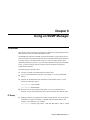
8 Using an SNMP Manager
Overview . . . . . . . . . . . . . . . . . . . . . . . . . . . . . . . . . . . . . . . . . . . . . . . . . . . . . . . . . . . . . . . . . . . . 8-1
IP Setup. . . . . . . . . . . . . . . . . . . . . . . . . . . . . . . . . . . . . . . . . . . . . . . . . . . . . . . . . . . . . . . . . . 8-1
SNMP Setup . . . . . . . . . . . . . . . . . . . . . . . . . . . . . . . . . . . . . . . . . . . . . . . . . . . . . . . . . . . . . . 8-2
9 Troubleshooting the SNMP Manager
Procedure for Troubleshooting . . . . . . . . . . . . . . . . . . . . . . . . . . . . . . . . . . . . . . . . . . . . . . . . . . . 9-1
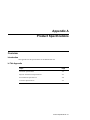
A Product Specifications
Overview . . . . . . . . . . . . . . . . . . . . . . . . . . . . . . . . . . . . . . . . . . . . . . . . . . . . . . . . . . . . . . . . . . . .A-1
Introduction. . . . . . . . . . . . . . . . . . . . . . . . . . . . . . . . . . . . . . . . . . . . . . . . . . . . . . . . . . . . . . .A-1
In This Appendix . . . . . . . . . . . . . . . . . . . . . . . . . . . . . . . . . . . . . . . . . . . . . . . . . . . . . . . . . .A-1
vii
B Console Command Line Reference
Overview . . . . . . . . . . . . . . . . . . . . . . . . . . . . . . . . . . . . . . . . . . . . . . . . . . . . . . . . . . . . . . . . . . . . B-1
Introduction . . . . . . . . . . . . . . . . . . . . . . . . . . . . . . . . . . . . . . . . . . . . . . . . . . . . . . . . . . . . . . B-1
In This Appendix . . . . . . . . . . . . . . . . . . . . . . . . . . . . . . . . . . . . . . . . . . . . . . . . . . . . . . . . . . B-1
Console Commands. . . . . . . . . . . . . . . . . . . . . . . . . . . . . . . . . . . . . . . . . . . . . . . . . . . . . . . . . . . . B-2
System Commands . . . . . . . . . . . . . . . . . . . . . . . . . . . . . . . . . . . . . . . . . . . . . . . . . . . . . . . . . . . . B-3
IP Commands . . . . . . . . . . . . . . . . . . . . . . . . . . . . . . . . . . . . . . . . . . . . . . . . . . . . . . . . . . . . . . . . B-4
SNMP Commands. . . . . . . . . . . . . . . . . . . . . . . . . . . . . . . . . . . . . . . . . . . . . . . . . . . . . . . . . . . . . B-5
Switching Database Commands . . . . . . . . . . . . . . . . . . . . . . . . . . . . . . . . . . . . . . . . . . . . . . . . . . B-6
Virtual LAN Commands . . . . . . . . . . . . . . . . . . . . . . . . . . . . . . . . . . . . . . . . . . . . . . . . . . . . . . . . B-7
Spanning Tree Commands . . . . . . . . . . . . . . . . . . . . . . . . . . . . . . . . . . . . . . . . . . . . . . . . . . . . . . B-8
Port Configuration Commands . . . . . . . . . . . . . . . . . . . . . . . . . . . . . . . . . . . . . . . . . . . . . . . . . . . B-9
Switching Statistics Commands . . . . . . . . . . . . . . . . . . . . . . . . . . . . . . . . . . . . . . . . . . . . . . . . . B-10
C System Default Values
Overview . . . . . . . . . . . . . . . . . . . . . . . . . . . . . . . . . . . . . . . . . . . . . . . . . . . . . . . . . . . . . . . . . . . . C-1
Introduction . . . . . . . . . . . . . . . . . . . . . . . . . . . . . . . . . . . . . . . . . . . . . . . . . . . . . . . . . . . . . . C-1
In This Appendix . . . . . . . . . . . . . . . . . . . . . . . . . . . . . . . . . . . . . . . . . . . . . . . . . . . . . . . . . . C-1
D Associated Documents
Overview . . . . . . . . . . . . . . . . . . . . . . . . . . . . . . . . . . . . . . . . . . . . . . . . . . . . . . . . . . . . . . . . . . . . D-1
Introduction . . . . . . . . . . . . . . . . . . . . . . . . . . . . . . . . . . . . . . . . . . . . . . . . . . . . . . . . . . . . . .D-1
In This Appendix . . . . . . . . . . . . . . . . . . . . . . . . . . . . . . . . . . . . . . . . . . . . . . . . . . . . . . . . . . D-1
Documents. . . . . . . . . . . . . . . . . . . . . . . . . . . . . . . . . . . . . . . . . . . . . . . . . . . . . . . . . . . . . . . . . . . D-2
How to Order Additional Documentation. . . . . . . . . . . . . . . . . . . . . . . . . . . . . . . . . . . . . . . . . . . D-3
Correspondence. . . . . . . . . . . . . . . . . . . . . . . . . . . . . . . . . . . . . . . . . . . . . . . . . . . . . . . . . . . . . . .D-4
Documentation Comments. . . . . . . . . . . . . . . . . . . . . . . . . . . . . . . . . . . . . . . . . . . . . . . . . . . D-4
Online Services . . . . . . . . . . . . . . . . . . . . . . . . . . . . . . . . . . . . . . . . . . . . . . . . . . . . . . . . . . . D-4
E Service Information and Support
Overview . . . . . . . . . . . . . . . . . . . . . . . . . . . . . . . . . . . . . . . . . . . . . . . . . . . . . . . . . . . . . . . . . . . . E-1
Introduction . . . . . . . . . . . . . . . . . . . . . . . . . . . . . . . . . . . . . . . . . . . . . . . . . . . . . . . . . . . . . . E-1
In This Appendix . . . . . . . . . . . . . . . . . . . . . . . . . . . . . . . . . . . . . . . . . . . . . . . . . . . . . . . . . . E-1
Warranty Service. . . . . . . . . . . . . . . . . . . . . . . . . . . . . . . . . . . . . . . . . . . . . . . . . . . . . . . . . . . . . . E-2
viii
Figures
2-1
2-2
2-3
2-4
3-1
3-2
3-3
Typical Configuration in a Single Server Environment . . . . . . . . . . . . . . . . . . . . . . . . . . . . . . . . 2-3
Typical Configuration in a Multiple Server Environment . . . . . . . . . . . . . . . . . . . . . . . . . . . . . . 2-4
Typical Configuration in a 100Mbps Environment . . . . . . . . . . . . . . . . . . . . . . . . . . . . . . . . . . . 2-5
Typical Configuration in a Multiple Server/WAN Environment. . . . . . . . . . . . . . . . . . . . . . . . . 2-6
Status LEDs on a 10/100 Port. . . . . . . . . . . . . . . . . . . . . . . . . . . . . . . . . . . . . . . . . . . . . . . . . . . . 3-3
RJ45 Connector Pinouts . . . . . . . . . . . . . . . . . . . . . . . . . . . . . . . . . . . . . . . . . . . . . . . . . . . . . . . . 3-4
Crossed Cable Pinout . . . . . . . . . . . . . . . . . . . . . . . . . . . . . . . . . . . . . . . . . . . . . . . . . . . . . . . . . . 3-4
Tables
A-1
A-2
A-3
A-4
A-5
B-1
B-2
B-3
B-4
B-5
B-6
B-7
B-8
B-9
C-1
Technical Specifications. . . . . . . . . . . . . . . . . . . . . . . . . . . . . . . . . . . . . . . . . . . . . . . . . . . . . . . A-2
Physical and Electrical Specifications . . . . . . . . . . . . . . . . . . . . . . . . . . . . . . . . . . . . . . . . . . . . A-3
Environmental Specifications. . . . . . . . . . . . . . . . . . . . . . . . . . . . . . . . . . . . . . . . . . . . . . . . . . . A-4
Acoustics . . . . . . . . . . . . . . . . . . . . . . . . . . . . . . . . . . . . . . . . . . . . . . . . . . . . . . . . . . . . . . . . . . A-5
German Acoustical Specifications . . . . . . . . . . . . . . . . . . . . . . . . . . . . . . . . . . . . . . . . . . . . . . . A-6
Console Commands . . . . . . . . . . . . . . . . . . . . . . . . . . . . . . . . . . . . . . . . . . . . . . . . . . . . . . . . . . B-2
System Commands . . . . . . . . . . . . . . . . . . . . . . . . . . . . . . . . . . . . . . . . . . . . . . . . . . . . . . . . . . . B-3
IP Commands . . . . . . . . . . . . . . . . . . . . . . . . . . . . . . . . . . . . . . . . . . . . . . . . . . . . . . . . . . . . . . . B-4
SNMP Commands . . . . . . . . . . . . . . . . . . . . . . . . . . . . . . . . . . . . . . . . . . . . . . . . . . . . . . . . . . . B-5
Switching Database Commands . . . . . . . . . . . . . . . . . . . . . . . . . . . . . . . . . . . . . . . . . . . . . . . . . B-6
Virtual LAN Commands . . . . . . . . . . . . . . . . . . . . . . . . . . . . . . . . . . . . . . . . . . . . . . . . . . . . . . B-7
Spanning Tree Commands . . . . . . . . . . . . . . . . . . . . . . . . . . . . . . . . . . . . . . . . . . . . . . . . . . . . . B-8
Port Configuration Commands . . . . . . . . . . . . . . . . . . . . . . . . . . . . . . . . . . . . . . . . . . . . . . . . . . B-9
Switching Statistics Commands . . . . . . . . . . . . . . . . . . . . . . . . . . . . . . . . . . . . . . . . . . . . . . . . B-10
System Default Values . . . . . . . . . . . . . . . . . . . . . . . . . . . . . . . . . . . . . . . . . . . . . . . . . . . . . . . . C-2
ix
Preface
Overview
About This Guide
This guide describes the DIGITAL MultiSwitch 300 and procedures for installing and
configuring it.
Intended Audience
This guide is intended for use by personnel who install and configure the DIGITAL
MultiSwitch 300 system.
xi
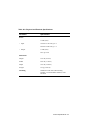
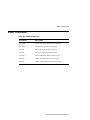
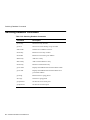
Organization
Organization
This guide is organized as follows:
xii
Chapter/
Appendix
Description
1
Provides an overview of and describes the features of the
MultiSwitch 300.
2
Describes typical configurations of networks using the
MultiSwitch 300.
3
Details the installation and setup of the MultiSwitch 300.
4
Identifies the process for troubleshooting problems with the
MultiSwitch 300.
5
Provides an overview of and describes the features of the SNMP
Agent.
6
Describes how to access the Administrative Interface.
7
Details the use of the Administrative Interface and identifies the
commands available at the console.
8
Describes how to use an SNMP Manager with the MultiSwitch
300.
9
Identifies the process for troubleshooting problems with the
SNMP Manager.
A
Provides product specifications for the MultiSwitch 300.
B
Lists and describes all the command line console commands
available through the Administrative Interface.
C
Identifies the system default values.
D
Provides a list of associated documents and ordering information.
E
Service Information and Support
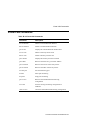
Conventions
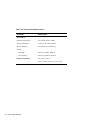
Conventions
This guide uses the following conventions:
Convention
Description
Special Type
This special type in examples indicates system output.
boldface
Indicate user input at the console.
<Italics>
Italic type in examples indicates variable user input.
<Return>
Indicates that you should press the Return key.
xiii
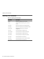
Safety
Safety
Any warning or caution that appears in this guide is defined as follows:
xiv
WARNING
Contains information to prevent personal injury.
CAUTION
Contains information to prevent damage to
equipment.
VORSICHT
Enthält Informationen, die beachtet werden müssen
um den Benutzer vor Schaden zu bewahren.
ACHTUNG
Enthält Informationen, die beachtet werden müssen
um die Gerate vor Schaden zu bewahren
DANGER
Signale les informations destinées à prévenir les
accidents corporels.
ATTENTION
Signale les informations destinées à prévenir la
détérioration du matériel.
AVISO
Contiene información para evitar daños personales.
PRECAUCIÓN
Contiene información para evitar daños al equipo.
Chapter 1
Introduction
Product Description
The DIGITAL MultiSwitch 300 is a 12-port Fast Ethernet switch featuring eight
autonegotiating 10/100BaseTX ports and up to four additional 10/100BaseTX/FX
uplink ports. The MultiSwitch 300 provides a cost-effective solution for increasing the
available bandwidth and distance of Fast Ethernet installations by dividing the network
into segments and insulating each from the others’ local traffic. Since each port
autonegotiates either a 10 Mb/s or a 100 Mb/s connection, the MultiSwitch 300 allows
you to upgrade your existing 10 Mb/s network devices to 100 Mb/s as needed.
Each switch supports up to 4096 addresses. Up to four additional ports are available
by using 10/100BaseTX/FX plug-in modules (two ports per module are added).
Delays in data transfer are eliminated through the MultiSwitch 300 parallel store-andforward architecture with direct port-to-port transfer. Its proprietary hardware enables
the switch to handle wire speed reception, including broadcast and multicast frames,
through a filtering and forwarding rate of 700,000 packets per second. Unique
selective flow control improves performance by preventing lost packets due to buffer
overload. This feature is critical for sliding window network operating systems (NOSs)
such as TCP/IP and Novell NetWare 4.2, and is available on 10/100 Mb/s half-duplex
ports and 100 Mb/s full-duplex ports.
Up to 200 Mb/s point-to-point connections over standard Fast Ethernet cabling can be
achieved with full-duplex adapter cards made for supporting high-end workstations
and applications. Furthermore, full-duplex operation eliminates the Fast Ethernet
distance limitation of 200 to 400 m (depending on the media type), enabling
transmission distances up to 18 km over fiber optic cable.
Broadcast and security domains may be defined, creating virtual networks that allow
secure workgroups and better manage network traffic. Any filter can be defined based
on multicast/broadcast, source port, destination port, and destination address.
Additional VLAN features include the ability to set virtual broadcast domains and
virtual security LANs. Further reliability is provided through complete runt and CRC
filtering.
Introduction 1-1
The MultiSwitch 300 can operate as a standalone unit or with any other Ethernet
offering from Digital Equipment Corporation. The unit does not require an NMS
agent; however, it can be monitored and controlled through any SNMP-based NMS, if
desired.
1-2 Introduction
Features
Features
•
8 RJ45 STP autonegotiating 10/100 ports
•
Two expansion slots supporting up to 2 TX, 2 FX
•
Standard 19-inch rack-mount chassis (rack-mount kit included)
•
Auto-ranging power supply (automatically adjusts to any voltage between 90 Vac
and 264 Vac at 50/60 Hz)
•
Half/full duplex selectable on each port via management
•
Flow control selectable on each port
•
4096 address cache entries
•
Extensive custom filtering table
•
Serial console port with password protection
•
Downloadable flash firmware (serial or TFTP)
•
SNMP support
•
Spanning Tree
•
RMON support built in for statistics, history, alarms, and events (Group 1, 2, 3,
and 9)
•
Port-based VLAN
•
Port mirroring
•
Telnet
Introduction 1-3
Switch and Network Management Systems
Switch and Network Management Systems
The MultiSwitch 300 can be monitored and controlled through the DIGITAL
MultiSwitch 300 Manager application, or through a generic SNMP NMS. See the
DIGITAL MultiSwitch 300 Manager User’s Guide for information about how the
DIGITAL NMS works.
The MultiSwitch 300 does not require an NMS; however, network management
functions greatly assist monitoring and controlling your network. For example,
through SNMP you can monitor port statistics, configure individual ports, and view
bridging information.
1-4 Introduction
Chapter 2
Typical Configurations
Configuring Your Network
Links to a file server and links between switches often create bandwidth bottlenecks.
When a dedicated 10 Mb/s link is not fast enough, or when a network-wide upgrade
path is planned, Fast Ethernet is a viable solution.
Links to a File Server
Intense client/server traffic on the LAN may limit the overall performance of a
network. Fast Ethernet allows the file server to communicate at 100 Mb/s to a 10/100
switch such as the MultiSwitch 300, which then distributes the traffic to several 100
Mb/s or 10 Mb/s ports.
Links Between Switches
Links that run at more than 10 Mb/s are essential between switches. If the link between
two switches is at 10 Mb/s, then only one full-speed Ethernet stream can be handled at
any given time. With the 100 Mb/s connection of Fast Ethernet, 10 full-speed Ethernet
streams may be handled simultaneously using half-duplex mode. With full-duplex
mode, 20 full-speed symmetrical streams may be handled simultaneously.
An Ethernet to Fast Ethernet switch presents the network administrator with a possible
upgrade path. At first, the switch can be used simply to segment the existing network,
immediately boosting performance. Next, with the addition of a single 100 Mb/s
network interface card (NIC), a file server can be migrated to Fast Ethernet, increasing
its availability. As needed, additional file servers or individual users can be moved to
Fast Ethernet while leaving all other parts of the network running as usual. If some of
the shared Ethernet segments are still congested, but don’t warrant a full 100 Mb/s
connection, additional switches may be added to further divide the shared segments,
creating a small collapsed 100 Mb/s backbone and small switched 10 Mb/s segments.
The MultiSwitch 300s autonegotiating 10/100 ports provide unmatched flexibility
because they allow the network administrator to upgrade the network devices to 100
Mb/s as needed; existing 10 Mb/s hardware is fully compatible with the MultiSwitch
300.
Typical Configurations 2-1
Finally, if a network’s bandwidth needs outstrip even 100 Mb/s shared workgroups,
the MultiSwitch 300 can be used with the DIGITAL MultiSwitch 600 family of
products to create a fully switched Fast Ethernet network.
2-2 Typical Configurations
Configuration Examples
Configuration Examples
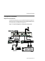
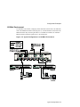
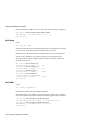
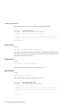
Single Server Environment
In a network with a single server, or even in a collapsed backbone with a single server,
a good way to achieve bandwidth improvement is to use a dedicated 100 Mb/s Fast
Ethernet link to the server. Both the 10 Mb/s workgroups and the 100 Mb/s server can
be connected directly to the MultiSwitch 300 (Figure 2-1).
Figure 2-1: Typical Configuration in a Single Server Environment
Typical Configurations 2-3
Configuration Examples
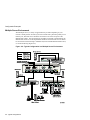
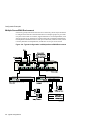
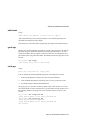
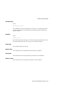
Multiple Server Environment
With multiple servers, a variety of approaches may be taken depending on your
network’s traffic patterns. If each of your network users has a particular primary server
that they use, then that server should be connected to one of the fast ports of the
MultiSwitch 612EX. The second fast port should be connected to the backbone; the
MultiSwitch 300 serves as the departmental backbone switch and the servers should
be connected to it either through a 100 Mb/s hub, such as the MultiSwitch Hub 612TX,
or connected directly (Figure 2-2).
Figure 2-2: Typical Configuration in a Multiple Server Environment
2-4 Typical Configurations
Configuration Examples
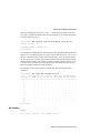
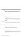
100 Mb/s Environment
In a 100 Mb/s environment, workgroup clients should be connected to a 100 Mb/s hub
such as the MultiSwitch Hub 612TX (Figure 2-3). All hubs should be connected to the
MultiSwitch 300. By connecting the hubs to a switched environment, the 100 Mb/s
BaseTX distance limitation applies only to the workgroups.
Figure 2-3: Typical Configuration in a 100 Mb/s Environment
Typical Configurations 2-5
Configuration Examples
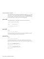
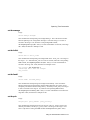
Multiple Server/WAN Environment
If the users typically utilize more than one server extensively, then it may be beneficial
to configure their network so that machines that serve multiple groups are given their
own port on the switch. For instance, suppose that there are several departments, each
with its own file server, and there is a single firewall router connected to the backbone.
Each department should then have its own port on the switch, while the router, which
is used by members of all departments, should have its own port on the switch.
Figure 2-4: Typical Configuration in a Multiple Server/WAN Environment
2-6 Typical Configurations
Excessive Flow Control
Excessive Flow Control
During times of peak network usage, you may occasionally see the flow control
indicator (Fc) flash. This is normal. However, either of the following conditions could
indicate a problem with your network configuration: if the indicator stays lit for more
than a few seconds at a time, or there is an excessive number of flow controls reported
by the NMS. A port’s flow control indicator flashes whenever a packet is received that
needs to be forwarded to a port that already has too many packets queued for it. This
indicates a temporary over-bandwidth situation on one port; that is, the total traffic
attempting to be forwarded to the port was in excess of 100 Mb/s, and the switch’s
buffers were full. This typically occurs when there are several fast machines on
different ports trying to access a machine across the switch. If this occurrence was due
to an unusual event, then no further action is necessary. If this is part of the normal
usage pattern for the network, then the station(s) causing the flow control to activate
should be identified and moved to the same segment as the machine it is
communicating with.
When a situation arises where Ethernet bandwidth is insufficient for the traffic, there
are only two possible actions: drop packets or use flow control. Buffering packets
works for a time period, but an extended over-bandwidth situation will eventually
overflow buffers and cause dropped packets. Flow control is an alternative solution,
since it relies on Ethernet’s inherent collision detection mechanism to relieve
temporary over-bandwidth situations (half-duplex mode only).
Typical Configurations 2-7
Full-Duplex Flow Control
Full-Duplex Flow Control
Normally, flow control is not available on full-duplex ports. This is because the switch
generates flow controls by sending a JAM signal whenever it is unable to forward a
frame. When the host NIC receives the JAM, it will retransmit the packet from
hardware buffers. This is faster than relying on higher level software transport layers,
which must first detect the dropped packet via a time-out mechanism, then regenerate
and re-queue it. Since there are no collisions in full-duplex mode, the traditional
method of generating a flow control will not work. However, the MultiSwitch 300
implements a proprietary flow control protocol on full-duplex ports by sending a
special frame that another MultiSwitch 300 interprets as a signal to briefly halt
transmission to the overloaded port; this will alleviate the over-bandwidth situation.
To gain the advantages of flow control when using full-duplex, both switches must be
MultiSwitch 300’s.
NOTE
Full-duplex MultiSwitch 300 flow control works only between MultiSwitch 300s.
Full-duplex flow control should NOT be enabled on a MultiSwitch 300 port if the
device on the other end is not a MultiSwitch 300 (that is, MultiSwitch 6xx,
VNswitch, other vendors’ switches).
2-8 Typical Configurations
Repeater Count Limits
Repeater Count Limits
A switch does not count as a repeater. Each of the segments connected to a switch port
can support a full Ethernet LAN; there can be up to two Class II hubs or one Class I
hub between the switch and any station(s).
If you have specific questions about your network configuration, or have a particularly
difficult network, please call your DIGITAL Service Representative. (See Chapter 4,
MultiSwitch 300 Troubleshooting.)
NOTE
The MultiSwitch 300 can handle a sustained load of 530 Mb/s or 700 Kp/s.
Exceeding these capabilities for an extended period of time will result in excessive
flow control. If this happens, the network should be reconfigured to decrease the
load.
Typical Configurations 2-9
Chapter 3
Installation and Setup
Installing the MultiSwitch 300
The following instructions will enable you to successfully install the MultiSwitch 300
in your network.
Step 1:
Determine the Best Location for the Switch
Install the unit in a 19-inch rack using the enclosed rackmount ears, or place the unit
on a secure, flat surface after attaching the enclosed rubber feet. Ensure that the switch
is within reach of the necessary connections (power outlet, Ethernet connections, and,
if the unit will be monitored through the serial port, a PC, UNIX workstation, or
modem).
Step 2:
Plug in the Switch
Simply connect the power cord to the switch and an outlet. Turn the power switch to
the ON position. The power supply automatically adjusts to any outlet providing
between 90 Vac and 264 Vac at 50/60 Hz.
Step 3:
Connect the Ethernet Devices
For optimum performance, the Ethernet segments connected to the MultiSwitch 300
must be configured so that machines on a given port communicate primarily among
themselves; most traffic does not need to cross the switch.
NOTE
The default configuration of all ports is half-duplex mode. To change this default,
you must use the Administrative Interface or an SNMP manager.
To connect an Ethernet device to a MultiSwitch 300 port:
•
The autonegotiating ports on the MultiSwitch 300 are designed to be connected
directly to a hub, using a crossed patch cable. To connect a workstation to the
switch, you must use either a hub between them, or a straight cable.
Installation and Setup 3-1
To use full-duplex mode:
•
Step 4:
Full-duplex mode may be selected via management. Consult Chapter 6,
Accessing the SNMP Agent, or the DIGITAL MultiSwitch 300 Manager User’s
Guide for port configuration.
What to Do Next
If you are using the MultiSwitch 300 as a standalone device (not under NMS control),
you have completed the installation and setup of the Switch.
3-2 Installation and Setup
Using the MultiSwitch 300
Using the MultiSwitch 300
Operation of the switch requires minimal user intervention. The unit automatically
learns the addresses of new stations as they appear, and will relearn addresses (up to
a limit of 4096) of new stations dynamically, if the network is reconfigured.
Understanding the LEDs
Each of the 10/100 ports has six status LEDs, as shown in Figure 3-1.
Xmt
Lights when this port transmits packets.
Rcv
Lights when this port receives packets, even if they are not forwarded.
Link
Lights whenever a link signal is received. This indicates that a
connection has been established.
Speed
Lights when the link is at 100 Mb/s, off when it is at 10 Mb/s.
Col/Fdx
Is a multipurpose indicator. It lights continuously when full-duplex
mode is enabled; otherwise, it is off, indicating half-duplex operation. It
blinks whenever a collision is detected.
Fc
If flow control is enabled on this port, this LED blinks whenever
flow control is activated.
Figure 3-1: Status LEDs on a 10/100 Port
FX Cabling
Fiber optic cabling is rapidly becoming a cost-effective alternative to Category 5 UTP.
Fiber’s falling cost, along with greater longevity, immunity to electrical interference,
greater transmission distance, and higher bandwidth capability make it a strong
alternative for new installations. The combination of fiber optics, Fast Ethernet, and
full-duplex operation yields a compelling solution for LAN congestion. The
MultiSwitch 300 supports up to 18 km over a single mode fiber optic cable, without a
repeater. However, this is not possible in half-duplex, since the maximum diameter of
a Fast Ethernet network is ~500 m. Full-duplex mode overcomes this limitation by
Installation and Setup 3-3
Using the MultiSwitch 300
allowing simultaneous transmission and reception, eliminating collisions. With this
combination, a 200 Mb/s link can be established between two switches separated by
any supported distance. This should be more than sufficient for most LAN
applications.
TX Cabling
The MultiSwitch 300 is an MDI-X device. Connections to other MDI-X devices, such
as another MultiSwitch 300 or a hub, should be made with a crossed Category 5 patch
cable (DIGITAL BN25G). The maximum cable length from a 100 Mb/s port is 100 m.
For a connection to an MDI device, such as a workstation, a straight Category 5 patch
cable should be used. The pinouts of the connectors are diagrammed in Figure 3-2
below. A crossed cable pinout is shown in Figure 3-3.
Figure 3-2: RJ45 Connector Pinouts
FEMALE RJ45 (MDI-X), INCLUDES MOST HUBS
1 RX+
5
Unused
2 RX-
6
TX-
3 TX+
7
Unused
4 Unused
8
Unused
Figure 3-3: Crossed Cable Pinout
FEMALE RJ45 (MDI), INCLUDES MOST NICS
3-4 Installation and Setup
1
TX+
5
Unused
2
TX-
6
RX-
3
RX+
7
Unused
4
Unused
8
Unused
Chapter 4
Troubleshooting the MultiSwitch 300
Procedure for Troubleshooting
If there are any operating problems with the MultiSwitch 300, follow the
troubleshooting steps below (in order). If you find that the switch is still not
functioning correctly, please contact your DIGITAL Service Representative.
1) Ensure that the unit is plugged into a grounded, functioning ac outlet providing
between 90 Vac and 264 Vac at 50/60 Hz. Check the power fuse and replace it if
blown.
CAUTION
For continued protection against fire, replace the power fuse with one that is the
same type and rating.
2) Review all link LEDs to ensure that those ports you believe should be functioning
are properly attached to a cable.
3) Verify that your cables are wired correctly; for example, use a UTP crossover
cable to connect another MDI-X device (such as a hub or switch) directly to a port.
Use a straight cable to directly connect a workstation. Refer to Figure 3-2 for the
proper connector pinouts.
4) Ensure that you are using Category 5 cabling if you are running at 100 Mb/s.
5) Review all link LEDs to ensure that those ports you believe should be functioning
are properly configured, and not disabled or partitioned. If the suspect ports are
disabled or do not seem configured properly, reconfigure the port through the
Administrative Interface or your SNMP managment software.
6) Review all full-duplex LEDs to ensure that those ports you believe should be
functioning are in the correct mode of operation.
7) If the flow control LED shows excessive activity, refer to Chapter 2 for a
discussion of how to best configure your network for operation with a switch.
Troubleshooting the MultiSwitch 300 4-1
8) Ensure that the equipment attached to the switch is properly configured.
If you encounter any situations or problems you cannot solve, obtain, if possible, the
following information, then contact your DIGITAL Service Representative:
•
The serial number of your switch and its hardware address.
•
The hardware version number from the label on the unit.
•
The firmware version number from the console screen or MultiSwitch 300
Manager application.
•
The configuration of the equipment that is being interfaced with the switch.
•
The sequence of events leading up to your problem.
•
Actions you have already taken.
4-2 Troubleshooting the MultiSwitch 300
Chapter 5
The SNMP Agent
Overview
The MultiSwitch 300 contains a built-in SNMP agent running on the SNMP
processor board. This allows each MultiSwitch 300 to be managed from a
centralized management station with any SNMP-compliant NMS.
The SNMP agent software complies with the following standards:
•
RFC 1155 - The Structure of Management Information (SMI) for TCP/IP Based
Internets, May 1990
•
RFC 1556 - Management Information Base (MIB) for Network Managers of TCP/
IP Based Internets, May 1990
•
RFC 1557 - The Simple Network Management Protocol (SNMP), May 1990
•
RFC 1213 - The Management Information Base II (MIB II), March 1991
•
RFC 1643 - Definitions of Managed Objects for the Ethernet-like Interface Types
•
RFC 1573 - Evolution of the Interfaces Group of MIB-II, January 1994
•
RFC 1493 - Definitions of Managed Objects for Bridges, July 1993
•
RFC 793 - Transmission Control Protocol
•
RFC 854 - Telnet Protocol Specification
•
RFC 1055 - Non-standard for transmission of IP datagrams over serial lines: SLIP,
January 1988
The SNMP agent utilizes UDP/IP (RFC 768, RFC 950, RFC 1071 and RFC 791) as
OSI layers 3 and 4 protocols, ICMP(RFC 792) and ARP(RFC 826) to complete the
UDP/IP protocol suite.
The UDP/IP stack implementation is conformant to:
•
RFC 1122 - Requirements for Internet hosts - communication layers
•
RFC 1123 - Requirements for Internet hosts - application and support
The SNMP Agent 5-1
The MultiSwitch 300 may be managed by any SNMP manager that conforms to the
above standards. It may be fully managed by the DIGITAL MultiSwitch 300 Manager
application.
5-2 The SNMP Agent
Chapter 6
Accessing the SNMP Agent
Connecting to the Administrative Interface
This section provides instructions for connecting a terminal to the console port on the
right-hand side of the front panel of the switch. The terminal must be used for the initial
setup of the SNMP Agent software and may be used to test the connection to the
network management station.
Cabling
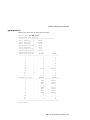
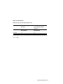
The console port is a serial port with a male DB-9 connector and a DTE-type pinout.
To connect this to another DTE-type serial port (as found on most computers and
terminals) a null modem cable is required.
MultiSwitch 300 (DTE) to Computer (DTE)
DB9 pin
DB9 pin
DB25 pin
2 (RX)
3 (TX)
2 (TX)
3 (TX)
2 (RX)
3 (RX)
5 (GND)
5
7
Communication Parameters
The Administrative Interface port is configured at the factory with the following
communication parameters:
•
9600 baud
•
No parity
•
Eight data bits
•
One stop bit
Accessing the SNMP Agent 6-1
Configuring the SNMP Agent
Configuring the SNMP Agent
Logging In to the Administrative Interface
The Administrative Interface is protected against usage by inappropriate personnel. To
access the Administrative Interface, the Network Administrator has to provide a name
and a password.
Please Login
username: userseven
password: (not echoed)
As configured at the factory, the password consists of a null string. To enter the first
time, just press <Return>. Once you have logged in to the Administrative Interface,
you may change the password to avoid undesired access.
Setting the IP Address
To manage the MultiSwitch 300 using an SNMP network management application or
to use the ping command to test the switch, you must assign an IP address, a netmask,
and a broadcast address. The IP address should be assigned by the Network
Administrator in accordance with the existing IP network.
Set the IP configuration with the set-ip-cfg command:
set-ip-cfg 192.1.1.64 255.255.255.0 192.1.1.255
NOTE
If the switch has no IP address, then the provided IP configuration will change the
running parameters as well as the NVRAM based database. If the switch was
already configured for the actual session, the parameters will change only the
NVRAM database. To use these new parameters, reset the switch using the warmreset command.
You may also use the set-ip command:
set-ip 192.1.1.64
In this case, the Agent will automatically determine the netmask and broadcast
address. See Chapter 7 for more information about SNMP configuration commands.
6-2 Accessing the SNMP Agent
Configuring the SNMP Agent
Testing the Installation
After you have completed the installation and configured the IP address, use the
Administrative Interface ping command to test for connectivity.
The ping command sends an echo request to the host specified in the command line.
For example, to test connectivity from the switch to a workstation with an IP address
of 192.168.1.2, use the following command:
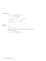
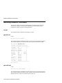
SYS_console> ping 192.168.1.2 2
SYS_console>
Use CTRL-C or ping-stop to stop the ping process
192.168.001.002 Alive. echo reply: id 8495, seq 1, echo-data-len 0
192.168.001.002 Alive. echo reply: id 8495, seq 2, echo-data-len 0
PING process stopped - statistics :
ICMP echo requests
:
2
ICMP echo responses :
2
PING process - press <CR> for prompt
SYS_console>
For more information on the ping command, see Chapter 7.
Accessing the Administrative Interface Remotely
After configuring the IP address of the switch, the Administrative Interface can be
accessed remotely through Telnet. All commands work exactly as if the serial interface
were being used. Please note that only one console session may be active at any given
time. This means that after the first Telnet session is established, all other Telnet
connections will be refused until the current session is closed. From the serial interface,
you can end the remote console session by pressing <Return> three times.
Accessing the SNMP Agent 6-3
Chapter 7
Using the Administrative Interface
Features of the Administrative Interface
The Administrative Interface provides the following:
•
Configuration of system parameters, including the serial line and/or the console’s
parameters
•
Configuration of the switch’s SNMP Agent parameters
•
Configuration of the ports’ physical and bridging parameters
•
Network performance monitoring
•
A fail-safe backup for in-band management
Entering Commands
Enter commands by typing the command name followed by zero or more parameters
and <Return>. For example, typing banner <Return> at the command prompt displays
the Administrative Interface logo.
Italicized command items are variables and represent values. For example,
<IPaddress> represents an IP address in dotted decimal notation as 123.1.2.3.
Command items in { }’s and separated by |’s represent alternatives for the command
argument. For example:
get-comm {read|write|*}
means you can type one of:
get-comm read
get-comm write
get-comm *
Using the Administrative Interface 7-1
If you enter a command incorrectly, a message is displayed indicating the type of error
that occurred. For example, typing a nonexistent command gives the following
message:
SYS_console> pin
command <pin> not found
If the command exists but the number of parameters is incorrect, the following
message is displayed:
SYS_console> ping
too few arguments
To get an explanation of the command’s parameters, add a question mark (?) after the
command name:
SYS_console> ping ?
ping
IP traffic generator
[arg #0] destination IP address
[arg #1] number of packets to send or 0 for endless ping
SYS_console> ping _
Note that the command is reprinted after the prompt, and you have only to add the
necessary parameters. If a question mark is added after the first parameter, then the
same explanation is provided and the previous command, including the provided
parameters, is re-displayed:
SYS_console> ping 129.1.1.7 ?
ping
IP traffic generator
[arg #0] destination IP address
[arg #1] number of packets to send or 0 for endless ping
SYS_console> ping 129.1.1.7 _
The Administrative Interface provides a history of the last commands. To obtain the
last command in the command history, press <!> or Ctrl-P at the prompt.
To correct a command line, you may use the following special keys (see the help-kbd
command):
•
<!> or Ctrl-P
For the previous command
•
Ctrl-W
To delete the previous word
•
Ctrl-U
To erase the entire line
7-2 Using the Administrative Interface
When, as a result of a command, more than one screen-full of text is to be printed, you
may continue to scroll or stop the process:
SYS_console> ip
IP related commands
-------------------------------------------------------------get-ip
show current IP address
set-ip
set IP address
get-ip-cfg
show current IP configuration
set-ip-cfg
set IP address , netmask and broadcast
clear-ip-cfg
clears the NVRAM based IP configuration
set-slip
set slip IP address
get-slip
get slip IP address
get-slip-cfg
show current IP configuration
set-slip-cfg
set IP address , netmask and broadcast
get-gatew
show default gateway
set-gatew
define default gateway
get-arp-tbl
display the ARP table
del-arp-entry deletes an entry/all entries(*) of the ARP table
add-arp-entry add an entry to the ARP table
get-bootp
retrieves the state of the BOOTP process
set-bootp
enables or disables the BOOTP process
ping
IP traffic generator
ping-stop
stop the ping process
Hit any key for more...
(type 'q' to quit)
SYS_console> _
Finally, you may press <Tab> to see the list of commands that start with the text you
already typed, for example:
SYS_console> get-c
Commands matching <get-c>
-------------------------------------------------------------get-comm
show current read or/and write community
get-con-matrix retrieves the VLAN connectivity matrix
get-colls-cnt gets the collision dist. counters per port
SYS_console>
Administrative Interface Command Structure
The Administrative Interface has several categories of commands:
•
Console commands: help, banner, serial line setup, console parameters setup
•
System commands: system status, reset commands, download commands, system
debug commands, initialize the NVRAM with defaults
•
IP commands: parameter setup, parameter and information display
•
SNMP agent commands: parameter setup, management and traps options
Using the Administrative Interface 7-3
•
Switching database commands: aging time management and switching database
entry management
•
Spanning Tree commands
•
Virtual LAN commands
•
Port configuration commands
•
Switching statistics command
7-4 Using the Administrative Interface
Console Commands
Console Commands
The console commands contain a set of commands that allows you to configure the
Administrative Interface parameters and user interface.
?
Typing ? at the Administrative Interface prompt displays a list of all the available
command topics and a short explanation about each. Typing one of the names on this
list will yield a list of the commands under that topic.
SYS_console> ?
Commands groups are:
-------------------console
Console related commands
system
System related commands
ip
IP related commands
snmp
SNMP related commands
switch-db
Switching Database related commands
vlan
Virtual LANS related commands
port-cfg
Port Configuration related commands
statistics
Switching Statistics related commands
sp-tree
Spanning Tree related commands
-----------------------------------------------------------use ! for prev. cmd, ^U to clr line, ^W to clr previous word
-----------------------------------------------------------SYS_console> _
help-kbd
This command lists the console function keys.
SYS_console>
? or TAB ! or ^P TAB
^U
^W
SYS_console>
help-kbd
for a list of the categories
for previous command
for command completion
to clear the line
to clear the previous word
_
banner
The banner command displays the MultiSwitch 300 Administrative Interface logo.
clear
The clear command clears the screen and displays the prompt.
Using the Administrative Interface 7-5
Console Commands
login
The login command exits the Administrative Interface, but does not disconnect a
Telnet session. This allows you to test a password (or other activity) without
reconnecting.
logout
The logout command finishes the actual Administrative Interface session. Any further
access requires that you log in again.
set-prompt
Usage:
set-prompt <new_prompt>
The set-prompt command allows you to set a new command line prompt for the
Administrative Interface. With the set-prompt command, you can set a more
meaningful prompt, such as a location of the switch, or the name of a workgroup. The
default prompt is SYS_console> _
SYS_console> set-prompt R&D_grp>
CLI prompt change in the NVRAM OK
R&D_grp>
set-passwd
The console requires you to enter a password to log in, preventing unauthorized access.
The set-passwd command allows you to change the console password. The system first
prompts you for the original password. Then you are asked to input a new password,
and then type it again for verification. At no time are any of the passwords echoed
back.
If you enter the old password incorrectly or fail to verify the new password correctly,
the password will not be changed:
SYS_console> set-passwd
Enter old password:
Enter new password:
Enter new password again:
New password not verified - password not changed!
SYS_console> _
7-6 Using the Administrative Interface
Console Commands
If the password change succeeds, the system responds accordingly:
SYS_console> set-passwd
Enter old password:
Enter new password:
Enter new password again:
CLI running password changed
CLI password change in NVRAM OK
Password changed!
SYS_console> _
Using the Administrative Interface 7-7
System Commands
System Commands
The system commands allow you to display and set the system-related parameters.
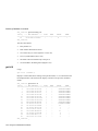
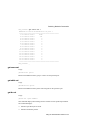
sys-stat
The sys-stat command displays general status information about the Ethernet switch
and its SNMP Agent hardware and software:
SYS_console> sys-stat
MultiSwitch 300
SNMP Agent Software - Version V0.1x Feb 8 1997 01:27:29
SNMP Object ID is : < 1.3.6.1.4.1.36.2.15.3.19 >
System MAC Address : 00-00-F8-00-0A-5C
Switching Data Base Size:
4096
Total uptime(hundredths of seconds ):
68840
Total uptime(days, hh:mm:ss format): 0 days, 0:11:28.40
i/f 1 -- description [Port 1
i/f 2 -- description [Port 2
i/f 3 -- description [Port 3
i/f 4 -- description [Port 4
i/f 5 -- description [Port 5
i/f 6 -- description [Port 6
i/f 7 -- description [Port 7
i/f 8 -- description [Port 8
i/f 9 -- description [Port
i/f 10 -- description [Port
i/f 11 -- description [Port
i/f 12 -- description [Port
SYS_console> _
- 10/100 BaseTX Ethernet Port] -- 10/100 BaseTX Ethernet Port] -- 10/100 BaseTX Ethernet Port] -- 10/100 BaseTX Ethernet Port] -- 10/100 BaseTX Ethernet Port] -- 10/100 BaseTX Ethernet Port] -- 10/100 BaseTX Ethernet Port] -- 10/100 BaseTX Ethernet Port] -9 - missing ] -- status [DOWN]
10 - missing ] -- status [DOWN]
11 - missing ] -- status [DOWN]
12 - missing ] -- status [DOWN]
status
status
status
status
status
status
status
status
[up]
[up]
[up]
[up]
[up]
[up]
[up]
[up]
The screen displays the following information:
•
Device name and type
•
SNMP Agent software version and release date
•
Device SNMP object ID
•
Device MAC address
•
System uptime in 1/100 seconds as well as in days, hours, minutes, and seconds
•
Interface description and status
7-8 Using the Administrative Interface
System Commands
warm-reset
The warm-reset command resets the SNMP Agent software without resetting the
switch. Nevertheless, the switch configuration is changed according to the values
stored in the NVRAM. This command permits you to refresh the switch configuration
after a change of the NVRAM parameters. The statistics counters are also reset by the
warm-reset command.
cold-reset
This command causes the switch to cold-reset. Cold reset is equivalent to power
cycling the switch.
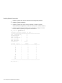
get-last-err
This command retrieves the most recent system failure for diagnostic purposes.
SYS_console> get-last-err
System information since the last hardware reset
-----------------------------------------------Software resets number : 0
The system never encountered a fatal error
SYS_console>
init-nvram
This command resets the nonvolatile RAM on the SNMP Agent to default values.
set-line-slip
Usage:
set-line-slip {9600|19200|38400}
This command changes the console serial port to SLIP mode for out of band SNMP
management. The argument to the command is the new baud rate for the interface.
The SLIP interface can be configured using the set-slip-cfg console command. You
can return the serial port to console mode by pressing <Return> three times in a row.
get-sw-file
This command retrieves the SNMP Agent software file name.
set-sw-file
Usage:
set-sw-file <filename>
Using the Administrative Interface 7-9
System Commands
Sets the name of the file downloaded by TFTP. This name must match the name of the
agent software file on the TFTP server. When TFTP is used, the per-packet
retransmission timeout value on the server must be increased to 10 seconds because
the SNMP Agent must first erase its flash EEPROM, which takes about 30 seconds.
get-rsw-file
This command retrieves the SNMP Agent software’s remote filename.
set-rsw-file
Usage:
set-rsw-file <remote_filename>
This command sets the SNMP Agent software’s remote filename for download. The
download is initiated with the sw-dnld command.
get-tftp-srvr
This command retrieves the TFTP download server’s IP address.
set-tftp-srvr
Usage:
set-tftp-srvr <ip_address>
This command sets the TFTP download server’s IP address.
sw-dnld
This command starts the SNMP software download from the predefined server.
get-par-file
This command retrieves the SNMP Agent parameters filename.
set-par-file
Usage:
set-par-file <filename>
Sets the name of the SNMP Agent parameters file downloaded by BootP. This
filename must match the name of the parameters file on the BootP server. The format
of the parameters file is:
<switch_hardware_address> : <read_comm> : <write_comm>
7-10 Using the Administrative Interface
System Commands
For example:
00-00-F8-00-01-23 : public : private
set-fg-parm
Usage:
set-fg-param <dest> <source> <fill_byte> <length>
This command sets the frame generator parameters. The dest and source parameters
are dash-separated hardware addresses in hexadecimal. The fill_byte parameter is a
single byte used to fill the entire packet except for the first 12 bytes. The length
parameter is the total length of the packet excluding CRC.
start-fg
Usage:
start-fg <dport> <count> <rate>
This command starts frame generation. The dport parameter is a hexadecimal bitmap
of which ports to generate traffic on. For example, a dport of 3E will send frames to
ports 2, 3, 4, 5, 6. The count parameter specifies the number of frames to send on each
interface. A count of 0 specifies an infinite number of packets. The rate parameter
specifies the number of packets per second to generate.
stop-fg
This command stops the Ethernet frame generator.
get-stst-level
This command shows the self-test level of the switch.
set-stst-level
Usage:
set-stst-level <level>
This command sets the self-test level of the switch. There are four levels of self-test:
none, short, long, and diagnostics. The self-test level is stored in NVRAM.
The default self-test level is short. In this mode, this power-up sequence is followed:
The OS/bootloader boots out of the ROM bank. The checksum of the SNMP software
flash bank is verified for consistency. The bootloader prints a # character to the serial
console. It then waits 5 seconds for a download command from a PC running the
Using the Administrative Interface 7-11
System Commands
firmware download software on the serial port. If, after 5 seconds, no download
request is detected, the bootloader will run the self-test out of ROM space. The selftest then runs in 10-Mbit loopback mode and performs these three tests:
1) Loopback test. This tests the basic send/receive functionality of each port with
varying frame sizes.
2) Broadcast test. This tests the basic forwarding capabilities of the bus by sending
broadcast frames from each port with varying frame sizes.
3) Bus B test. This tests the secondary bus.
If the self-test succeeds, the SNMP software is copied from the Flash into main
memory and is executed. If any part of the test fails, the systems halts.
In short mode, the switch wakes up after 30 to 40 seconds (depending on the number
of ports installed).
If the test level is none, no self-test is performed and the SNMP software is loaded
immediately after the download timeout expires.
If the test level is long, a RAM check is run on reset, and the self-test performs many
other tests. In this mode, the switch wakes up after about 2 minutes.
NOTE
The switch should be disconnected from the network while the long test is
executing.
If the test level is diagnostics, the self-test runs in interactive mode. INTERACTIVE
SELF-TEST SHOULD BE USED ONLY BY A QUALIFIED SWITCH ENGINEER.
Typing "quit" at the debugger prompt exits the tester and resumes the boot sequence.
The interactive mode can also be entered by typing three escapes (<Esc> <Esc>
<Esc>) in quick succession after the # character appears.
If, during boot, the boot ROM determines that the flash checksum is bad, it does NOT
time out during the download sequence. Instead, it waits there until a valid download
request is received on the console. As before, press the escape key quickly three times
to bring up the interactive self-test.
During the self-tests, you can skip individual tests by pressing any key during the test.
7-12 Using the Administrative Interface
IP Configuration Commands
IP Configuration Commands
This section lists general IP configuration commands available to the command line
interface. Sections that follow cover additonal IP commands including commands
pertaining to the ping ability of the SNMP Agent and pertinent features of the Address
Resolution Protocol.
get-ip
Shows the device’s current IP address, if any.
SYS_console> get-ip
The device has no IP Address defined
SYS_console> _
SYS_console> get-ip
The device IP address is: 129.001.001.064
SYS_console> _
get-ip-cfg
Shows the complete current IP configuration: address, network mask, and broadcast
address.
SYS_console> get-ip-cfg
The device has no IP Address defined
SYS_console>
SYS_console> get-ip-cfg
The device IP address, netmask and broadcast are:
IP address
: 129.001.001.064
IP netmask
: 255.255.255.000
IP broadcast : 129.001.001.255
set-ip
Usage:
set-ip <IP address>
Sets the IP address of the SNMP Agent. If no IP address was previously set (as is the
default factory configuration), the new value will be used immediately and saved into
NVRAM. Otherwise, the new value will only be stored in the NVRAM, and you must
execute a warm-reset to effect the change.
Using the Administrative Interface 7-13
IP Configuration Commands
set-ip-cfg
Usage:
set-ip-cfg <IPaddress> <netmask> <broadcast>
Sets IP address, network IP address, and broadcast IP address. If no IP configuration
was previously set (as is the default factory configuration), the new values are used
immediately and saved into NVRAM. If a previous IP configuration was being used,
the new configuration is saved in NVRAM for the next session. To use the newly
defined values immediately, reset the system using the warm-reset command.
NOTE
If the IP configuration is not specified, the agent will not respond to any in-band
requests, including ping messages.
SYS_console> set-ip-cfg 129.1.1.64 255.255.255.0 129.1.1.255
Device IP Address set for this session
Device IP Address change in the NVRAM OK
The device IP configuration in the next session will be:
IP address
: 129.001.001.064
IP netmask
: 255.255.255.000
IP broadcast : 129.001.001.255
SYS_console> set-ip-cfg 129.1.1.67 255.255.255.0 129.1.1.255
Device IP Address unchanged for this session
Device IP Address change in the NVRAM OK
The device IP configuration in the next session will be:
IP address
: 129.001.001.067
IP netmask
: 255.255.255.000
IP broadcast : 129.001.001.255
SYS_console> _
clear-ip-cfg
This command clears the NVRAM based IP configuration.
get-bootp
This command retrieves the current state of the BootP process.
7-14 Using the Administrative Interface
IP Configuration Commands
set-bootp
Usage:
set-bootp {enable|disable}
This command enables or disables BootP.
get-slip
This command retrieves the current SLIP address.
get-slip-cfg
This command retrieves the current SLIP configuration.
set-slip
Usage:
set-slip <IPaddress>
This command sets the SLIP address, see set-ip above for more information.
set-slip-cfg
Usage:
set-slip-cfg <IPaddress> <netmask> <broadcast>
This command sets the SLIP configuration. The arguments are similar to the set-ipcfg arguments.
get-gatew
Shows the default gateway. This command shows which default route will be used to
access a different IP network.
set-gatew
Usage:
set-gatew <IPaddress>
Sets the default gateway IP address. This command lets you specify the address of the
router used to access a different IP network . The default value for the default gateway
IP address is 0.0.0.0.
Using the Administrative Interface 7-15
IP Configuration Commands
SYS_console> set-gatew 129.1.1.1
Device Default Gateway change in the NVRAM OK
Device Default Gateway changed to : 129.1.1.1
SYS_console> get-gatew
Device default gateway address is : 129.001.001.001
SYS_console> _
get-def-ttl
This command returns the running default IP Time To Live value. This value (between
1 and 255) is the number of seconds this frame will be kept alive by routers along its
path.
set-def-ttl
Usage:
set-def-ttl <number>
This command modifies the default Time To Live value. The number parameter
(between 1 and 255) will be used as the new value.
7-16 Using the Administrative Interface
Ping Commands
Ping Commands
The ping command sends an ICMP echo request packet to a station. The ping process
is independent of the process that serves the Administrative Interface console. Thus,
the ping result (if any) printouts will be interleaved with the Administrative Interface
input/output.
Issuing further commands while the ping process is active is not recommended.
Starting a new ping session while another one is active is not supported and an error
message will be displayed.
ping
Usage:
ping <IPaddress> {<number>|0}
Pings the specified IP address a defined number of times, or for endless ping (0). The
ping process starts sending one datagram per second until the desired number of
datagrams are sent. It prints one line of output for every response that it receives. The
ping command does not return any output if there is no response. Normal response time
is 1 to 10 seconds.
The ping command is intended for testing the connectivity between the switch and an
IP station. It is not intended as a traffic generator. Thus, using the endless ping option
is not recommended.
If you started a long ping, stop it with Ctrl-C or issue a ping-stop command to stop it.
SYS_console> ping 192.168.1.2 4
SYS_console>
Use CTRL-C or ping-stop to stop the ping process
192.168.001.002 Alive. echo reply: id 2652, seq 1, echo-data-len 0
192.168.001.002 Alive. echo reply: id 2652, seq 2, echo-data-len 0
192.168.001.002 Alive. echo reply: id 2652, seq 3, echo-data-len 0
PING process stopped - statistics :
ICMP echo requests
:
3
ICMP echo responses :
3
PING process - press <CR> for prompt
This is an example of an unsuccessful ping:
SYS_console>
SYS_console> ping 129.1.1.88 4
SYS_console> _
Using the Administrative Interface 7-17
Ping Commands
If the host does not respond, the console prompt is printed and no output is added.
Failure to get an echo response from a host may be due to:
•
A bad physical connection.
•
A non-existent or inactive host.
•
Network Unreachable no corresponding entry in the routing table.
•
Destination Unreachable the default gateway failed to route the datagram.
•
Outdated ARP table information which requires flushing the ARP table with the
del-arp-entry command.
If there is an active ping process due to a previous long ping command and you try to
start a new ping, the command fails and an error message is displayed.
For example, start an endless ping to an unreachable host. No response will be
received. Now try to ping an existing host. The second ping will fail because the first
one is still active. The solution is to use the ping-stop command to stop the first active
ping process.
SYS_console> ping 129.1.1.1 1
SYS_console>
Use CTRL-C or ping-stop to stop the ping process
129.001.001.001 Alive. echo reply: id 297, seq 1, echo-data-len 8
PING process stopped - press <CR> for prompt
SYS_console> ping 129.1.1.88 0
SYS_console> ping 129.1.1.1 1
A ping process is active - can’t start another one
SYS_console> ping-stop
SYS_console> ping 129.1.1.1 1
SYS_console>
Use CTRL-C or ping-stop to stop the ping process
129.001.001.001 Alive. echo reply: id 297, seq 1, echo-data-len 8
PING process stopped - press <CR> for prompt
SYS_console> _
ping-stop
Stops the active ping process. Similar to Ctrl-C.
7-18 Using the Administrative Interface
Address Resolution Protocol Commands
Address Resolution Protocol Commands
get-arp-tbl
Shows the ARP table. The ARP table contains information relating IP addresses to
MAC addresses and interface numbers.
SYS_console> get-arp-tbl
IfIndex
IpAddress
MAC Address
====================================================
1
129.001.001.001
00-00-F8-2D-73-9C
SYS_console> add-arp-entry 129.1.1.200 00-00-F8-2b-59-ea 1
ARP Table Entry successfully added
SYS_console> get-arp-tbl
IfIndex
IpAddress
MAC Address
====================================================
1
129.001.001.001
00-00-F8-2D-73-9C
1
129.001.001.200
00-00-F8-2B-59-EA
SYS_console> del-arp-entry 129.1.1.200
ARP Table Entry with IP Address <129.1.1.200> removed
SYS_console> get-arp-tbl
IfIndex
IpAddress
MAC Address
====================================================
1
129.001.001.001
00-00-F8-2D-73-9C
SYS_console> _
add-arp-entry
Usage:
add-arp-entry <IPaddress> <mac_address> <Interface>
Adds an entry to the ARP table.
del-arp-entry
Usage:
del-arp-entry {<IPaddress>|*}
Deletes entries from the ARP table. If an IP address is specified, the matching ARP
entry will be deleted. If * is specified, the entire ARP table will be flushed. This
command should be used if the network topology has physically changed, for example,
if a management station has been moved from one segment to another, changing its
interface number.
Using the Administrative Interface 7-19
SNMP Commands
SNMP Commands
This section lists commands pertinent to configuring the SNMP Agent itself, that is,
access and trap configuration. It is split into two parts: SNMP community strings lists
the access modifications, and the trap section lists SNMP traps configuration
commands.
SNMP Community Strings
SNMP community strings authenticate access to the Management Information Base
(MIB). Community strings function as passwords embedded in every SNMP packet.
The community string must match one of the two community strings configured in the
switch for the message to be processed. There are two community strings, one for each
of the following types of access:
•
Read mode gives read access to all the objects in the MIB, but does not allow
write access.
•
Write mode gives read and write access to all objects in the MIB.
get-comm
Usage:
get-comm {read|write|*}
This command displays the SNMP community string for a given access mode (read
or write). If the access mode is specified as *, both the read and the write community
strings are displayed.
SYS_console> get-comm *
Current read community is: < public >
Current write community is: < private >
set-comm
Usage:
set-comm {read|write} <community-string>
This command lets you specify the SNMP community string for each of the two access
modes: read and write.
SYS_console> set-comm write password
New write community is: < password >
7-20 Using the Administrative Interface
SNMP Commands
SNMP Trap Message Commands
When the switch detects an extraordinary event, it generates a trap. A trap is a
notification message that may be sent to predefined network manager stations. A trap
event may be a reset (cold or warm), detection of a interface link status change, an
SNMP authentication failure due to an incorrect community string, etc.
The SNMP trap commands let you manage:
•
Whether or not the MultiSwitch 300 issues an authentication trap
•
The list of selected network manager stations that the switch-generated traps will
be sent to by the SNMP agent. The list has a maximum capacity of five entries.
get-auth
Displays the authentication trap mode: enabled or disabled.
set-auth
Usage:
set-auth {enable|disable}
This command allows you to modify the authentication trap mode. The default value
is enable, meaning that the switch will generate authentication traps. Changing the
mode to disable causes the switch to avoid sending authentication traps.
get-trap
Displays the list of traps receiving stations: their IP address and trap SNMP community
string.
SYS_console> get-traps
SNMP TRAP TABLE
===============
IPADDR
COMMUNITY
--------------------------------------------------192.168.001.065
----------testing
---------------------------------------------------
add-trap
Usage:
add-trap <IPaddress> <trap-community>
The add-trap command enters the IP address of the receiving station and the trap
community string that will appear in the trap message.
Using the Administrative Interface 7-21
SNMP Commands
SYS_console> add-trap 129.1.1.76 rnd
Entry 129.1.1.76 - rnd added
SNMP TRAP TABLE
===============
IPADDR
COMMUNITY
------------------------------------------129.001.001.065
----public
129.001.001.007
----trapcomm
129.001.001.076
----rnd
-------------------------------------------
del-trap
Usage:
del-trap <IPaddress>
The del-trap command can be used to remove a station from the trap table. The station
IP address must be provided.
SYS_console> del-trap 129.1.1.7
Entry 129.1.1.7 - trap comm deleted
7-22 Using the Administrative Interface
Switching Database Commands
Switching Database Commands
This section contains instructions for managing the switching database with the
Administrative Interface.
The switching database consists of 4096 entries. Each active entry contains the
information relevant to an end station, characterized by its Ethernet MAC address.
Each entry contains the following information:
•
lock
If on (denoted as a +), the entry will not be deleted by the switch aging process
(static entry). If off (denoted as a -), this is a dynamic entry that may be
automatically deleted by the switch aging process if the workstation is not active
during an aging time period.
•
self (not user configurable)
If on (denoted as a +), the entry is a system address. Such addresses are the
switch’s individual and group addresses, as well as other address added by the
management system. If off (denoted as a -), the entry contains the MAC address
of a station on the connected network.
•
dport
The destination port to which frames with the stated address will be forwarded.
Applies only if the address is not a custom filter.
•
The MAC address contained in an entry or given as a parameter is printed as a 6byte, hexadecimal sequence, separated by dashes:
00-00-F8-00-01-29
•
The index contained in the following commands is an integer number between 1
and the maximum size of the switching database table (4096).
The first section, virtual addresses, lists commands relevant to standard MAC
addresses, such as determining the behavior of the switch when presented with a
particular address. The second section, custom filtering, lists commands pertinent to
the custom filtering capabilities of the MultiSwitch 300.
Virtual Addresses
get-lt-entry
Usage:
get-lt-entry <index>
Displays the entry at the specified index in the switching database.
Using the Administrative Interface 7-23
Switching Database Commands
SYS_console> get-lt-entry 19
Entry ---- MAC Address ---- LOCK
SELF
DPORT
MGMT
==============================================================
19
00-00-F8-00-59-E6
8
SYS_console>
The entry described is:
•
Entry number 19
•
MAC address 00-00-F8-00-59-E6
•
Not a static entry (it will be aged out. Lock is off.)
•
Is not a system address (Self is off.)
•
The frame will be forwarded only to the port 8
•
Not forwarded to the management (Mgmt is off.)
get-lt-16
Usage:
get-lt-16 {<index>|*}
Displays 16 learn table entries starting at the specified index, or * to continue from the
last displayed index. The format of the display is similar to the previous command
format.
SYS_console> get-lt-16 6
Entry ---- MAC Address ---- LOCK
SELF
DPORT
MGMT
==============================================================
6
00-00-F8-20-20-D5
+
+
-CUSTOM FILTER7
00-00-F8-20-20-D6
+
+
-CUSTOM FILTER8
00-00-F8-20-20-D7
+
+
-CUSTOM FILTER9
00-00-F8-20-20-D8
+
+
-CUSTOM FILTER10
00-00-F8-20-20-D9
+
+
-CUSTOM FILTER11
00-00-F8-20-20-D10
+
+
-CUSTOM FILTER12
00-00-F8-20-20-D11
+
+
-CUSTOM FILTER13
FF-FF-FF-FF-FF-FF
+
-CUSTOM FILTER14
00-80-C2-00-00-00
+
-CUSTOM FILTER19
00-20-C5-00-59-E6
12
20
00-00-92-94-01-54
1
21
00-C0-1D-01-06-20
1
22
00-00-F8-2B-0A-26
11
23
00-00-F8-29-1E-DE
4
24
00-00-F8-2B-17-37
4
25
08-00-20-76-72-89
2
SYS_console> _
7-24 Using the Administrative Interface
Switching Database Commands
SYS_console> get-lt-16 *
Entry ---- MAC Address ---- LOCK
SELF
DPORT
MGMT
==============================================================
26
00-00-F8-11-06-AD
12
27
00-00-F8-2B-59-EA
3
28
00-00-F8-2D-99-3A
7
29
00-00-F8-16-80-7C
5
30
00-00-C0-60-A7-B9
5
31
00-00-F8-1A-A1-69
5
32
00-00-F8-29-1E-EB
11
33
00-00-F8-2E-DF-15
5
34
00-00-F8-28-B4-1A
7
35
00-00-F8-2F-93-A7
4
36
00-40-33-32-A6-58
12
37
00-00-F8-15-70-5E
5
38
00-00-F8-1A-A1-5F
11
39
00-00-F8-28-B7-2A
5
40
00-00-F8-2B-16-3D
12
41
00-00-F8-15-B6-83
4
SYS_console> _
NOTE
The first few entries belong to the system. These entries contain important
information related to the SNMP Agent and should never be modified or removed.
Entries 18 and onward are self-learned MAC addresses, as indicated by the lock
= OFF and by self = OFF. These entries were each learned from the port stated in
the DPORT field.
find-lt-addr
Usage:
find-lt-addr <mac_address>
Search for a MAC address in the learn table. If the specified mac_address is found in
the switching database, an entry description as in the previous commands is displayed.
SYS_console> find-lt-addr 00-00-F8-2B-16-3D
Entry ---- MAC Address ---- LOCK
SELF
DPORT
MGMT
==============================================================
40
00-00-F8-2B-16-3D
12
SYS_console> _
Using the Administrative Interface 7-25
Switching Database Commands
If the requested MAC address is not in the learn table, an error message is displayed:
SYS_console> find-lt-addr 00-00-F8-2b-59-66
MAC Address - 00-00-F8-2b-59-66 - not in LT
SYS_console> _
del-lt-entry
Usage:
del-lt-entry <index>
Deletes the learn table entry at the specified index. If the entry deletion was successful
or if the entry is not ACTIVE, then the command will be successful.
Deleting entries with the self field set is prohibited since they are system addresses.
The del-lt-entry command is very powerful, allowing you to change the entire
switching database with the exception of the system MAC addresses. Therefore, it
should be used with care.
SYS_console> del-lt-entry 15
Deleting entry at index - 15 - OK
SYS_console> del-lt-entry 16
Deleting entry at index - 16 - OK
SYS_console> del-lt-entry 1
Deleting entry at index - 1 - failed
SYS_console> del-lt-entry 2
Cannot delete a System Address
Deleting entry at index - 2 - failed
SYS_console> _
del-lt-addr
Usage:
del-lt-addr <mac_address>
Deletes the learn table entry that matches mac_address.
The command fails if mac_address is not found in the learn table. Again, as stated in
the previous command, care should be taken when deleting system entries (self=ON).
SYS_console> del-lt-addr 00-00-F8-2b-59-4c
Deleting entry with MAC address - 00-00-F8-2b-59-4c OK
SYS_console> del-lt-addr 00-00-F8-2b-59-4c
MAC Address - 00-00-F8-2b-59-4c - not in LT
SYS_console> _
7-26 Using the Administrative Interface
Switching Database Commands
add-lt-addr
Usage:
add-lt-entry <mac_address> {lock-off|lock-on} <dport>
Adds a learn table entry to the switching database. The command parameters are
described at the beginning of this chapter.
Note that dport is a decimal number representing the number of the destination port.
get-lt-age
Displays the switching database aging time in seconds. The aging time is the timeout
period for aging out dynamically learned forwarding information entries. An entry
whose MAC address does not appear in the source field of an incoming packet for a
period equal to the aging time is discarded. The default value for the aging time is 300
seconds.
SYS_console> get-lt-age
The running aging time is: 300 seconds
set-lt-age
Usage:
set-lt-age {run|nvram|all} <aging_time>
Lets you modify the switching database aging time. The change may be done:
•
In the running database so that the new value is used immediately.
•
In the NVRAM, meaning that the change will occur only in the next session.
•
In both the running and the NVRAM databases.
The aging_time is in seconds. The factory default value is 300 seconds. Use a lower
value if the number of active workstations at a given moment is larger than the size of
the switching database. The aging time can be anywhere between 10 and 11,000
seconds.
SYS_console> set-lt-age
Aging Period update in
SYS_console> set-lt-age
Aging Period update in
Aging Period update in
SYS_console> _
run 280
the running database OK
all 100
NVRAM OK
the running database OK
Using the Administrative Interface 7-27
Switching Database Commands
Custom Filtering Commands
The custom filter entry for an address is shown on the screen as a matrix, in the
following format:
Here, the SRC column lists the available source ports (1 through the number of ports
on the switch). The other columns each represent an available destination port. If a +
mark is encountered, it represents a forwarding path. For example, as displayed below,
each source port (with the exception of port 3) will forward this frame to port 3.
SYS_console> get-lt-filter 00-00-F8-00-0A-5C
2
00-00-F8-00-0A-5C LOCK_ON
SELF_ON - CUSTOM FILTER SRC PORT to : MGMT P1 P2 P3 P4 P5 P6 P7 P8 P9 P10 P11 P12
===============================================================
1
+
2
+
3
+
4
+
5
+
6
+
7
+
8
+
9
+
10
+
11
+
12
+
-
get-lt-filter
Usage:
get-lt-filter <mac_address>
This command retrieves the learn table filter for the specified MAC address. See
above for an example.
add-cf-entry
Usage:
add-cf-entry {lock-on|lock-off|perm} <mac_address> <sport>
<dport>
This command adds a custom filter learn table entry for the hardware address
mac_address. The lock-on parameter indicates that the entry will not be aged out, but
will be lost upon reset. The lock-off parameter indicates that the entry can be aged out
normally. The perm parameter indicates the filter will be written to NVRAM and
restored upon reset. sport value is a hexadecimal bitmask of incoming ports (bit 0 is
port 1, bit 1 is port 2...) , and the dport value is a hexadecimal bitmask of outgoing ports
7-28 Using the Administrative Interface
Switching Database Commands
(bit 0 is the management port, bit 1 is port 1...). Packets arriving at the switch with
mac_address destination address from any port specified in sport will be transmitted
to all ports specified in dport.
SYS_console> add-cf-entry lock-on 00-00-F8-11-11-11 62 108
Add CF LT entry OK
CF Entry Update in NVRAM
SYS_console> _
OK
For example, the command above will send packets with destination MAC address 0000-F8-11-11-11 from source ports 2, 6, and 7 (62 in hexadecimal is 0 1 1 0 0 0 1 0 in
binary) to destination ports 3 and 8 (108 in hexadecimal is 1 0 0 0 0 1 0 0 0 in binary).
All other ports receive a value of 00, meaning that they will filter all frames with this
destination MAC address. For example, a packet with MAC address 00-00-F8-11-1111 with a source port other than sport will be filtered accordingly (but any previous
filters for this MAC address will still be obeyed).
For example, you may check the above custom filter entry with the get-lt-filter
command:
SYS_console> get-lt-filter 00-00-F8-11-11-11
69
00-00-F8-11-11-11 LOCK_ON
SELF_OFF - CUSTOM FILTER SRC PORT to : MGMT P1 P2 P3 P4 P5 P6 P7 P8 P9 P10 P11 P12
===============================================================
1
2
+
+
3
4
5
6
+
+
7
+
+
8
9
10
11
12
SYS_console>
del-cf-entry
Usage:
del-cf-entry {run|all} <mac_address> <sport>
Using the Administrative Interface 7-29
Switching Database Commands
This command deletes the custom filter learn table entry for address mac_address from
source port sport. The run option indicates that the entry will be deleted only from the
current running table. The all option indicates that the entry should be removed from
the non-volatile memory as well as from the current running table.
get-nv-cftbl
This command displays the custom filter table stored in nonvolatile memory.
NVRAM CUSTOM FILTERS TABLE
==============================
Entry ---- MAC Address --------------------------------1
00-00-F8-11-11-11
SYS_console>
get-nv-cfilt
Usage:
get-nv-cfilt <mac_address>
This command retrieves the custom filter associated with the specified mac_address
from the custom filter table stored in nonvolatile memory.
get-sport-hex
Usage:
get-sport-hex <port_number>
This command displays the list of source ports in hexadecimal. One or more port
numbers may be entered for the port_number value, separated by the hyphen symbol
(-).
SYS_console> get-sport-hex 11
Hex for Source Ports <12> is: 800
SYS_console>
SYS_console> get-sport-hex 3-4-5
Hex for Source Ports <3-4-5> is: 1c
SYS_console>
7-30 Using the Administrative Interface
Switching Database Commands
get-dport-hex
Usage:
get-sport-hex <port_number>
This command displays the list of destination ports in hexadecimal. One or more port
numbers may be entered for the port_number value, separated by the hyphen symbol
(-).
SYS_console> get-dport-hex 11
Hex for Dest Ports <12> is: 800
SYS_console>
SYS_console> get-dport-hex 3-4-5
Hex for Dest Ports <3-4-5> is: 1c
SYS_console>
Using the Administrative Interface 7-31
Virtual LAN Commands
Virtual LAN Commands
Virtual LANs can be used to limit the broadcast domain and to establish virtual workgroups.
•
The run option indicates that only the currently running configuration is changed.
Changes are not restored after a reset.
•
The nvram option indicates that only the configuration stored in nonvolatile
memory is changed. Changes do not take effect until a reset.
•
The all option indicates that both the currently running configuration and the
nonvolatile configuration is changed. Changes take effect immediately and are
restored after a reset.
get-con-matrix
Retrieves the current connectivity matrix for the switch. A table similar to the one
displayed earlier (Custom Filters) is displayed. Here, the first column is the source
port. The other columns are destinations to which frames from a given source port
(determined by which row) may be forwarded. Unlearned addresses will be forwarded
to all destinations marked with a + in the source port’s row. Learned addresses will be
forwarded to their destinations only if the destination is marked with a + in the source
port’s row.
SYS_console> get-con-matrix
VLAN CONNECTIVITY MATRIX
==========================
SRC PORT to : P1 P2 P3 P4 P5 P6 P7 P8 P9 P10 P11 P12
===============================================================
1
+
+
+
+
+
+
2
+
+
+
+
+
+
3
+
+
+
+
+
+
4
5
+
+
+
+
+
+
6
+
+
+
+
+
+
7
+
+
+
+
+
+
8
+
+
+
+
+
+
9
10
11
12
SYS_console>
7-32 Using the Administrative Interface
Virtual LAN Commands
get-vbc-matrix
Retrieves the current broadcast domain matrix for the switch. See above for a
description of the resulting table. Here, though, only the broadcast address will be
affected.
SYS_console> get-vbc-matrix
VBC CONNECTIVITY MATRIX
==========================
SRC PORT to : P1 P2 P3 P4 P5 P6 P7 P8 P9 P10 P11 P12
===============================================================
1
+
+
+
+
+
+
2
+
+
+
+
+
+
3
+
+
+
+
+
+
4
5
+
+
+
+
+
+
6
+
+
+
+
+
+
7
+
+
+
+
+
+
8
+
+
+
+
+
+
9
10
11
12
SYS_console>
set-vbc-domain
Usage:
set-vbc-domain {run|nvram|all} <port_list>
This command establishes a virtual broadcast domain. The port_list value is a dash
separated list of ports to group into a broadcast domain. For example, the following
command creates a virtual broadcast domain of ports 2, 5, 6, and 7:
set-vbc-domain all 2-5-6-7
del-vbc-domain
Usage:
del-vbc-domain {run|nvram} <domain_id>
This command deletes a virtual broadcast domain, as identified by get-vbc-tbl.
get-vbc-tbl
Usage:
get-vbc-tbl {run|nvram}
Using the Administrative Interface 7-33
Virtual LAN Commands
This command retrieves the list of defined virtual broadcast domains.
SYS_console> get-vbc-tbl run
RUNTIME
VIRTUAL BROADCAST DOMAIN TABLE
===========================================
VBC ID
P1 P2 P3 P4 P5 P6 P7 P8 P9 P10 P11 P12
===========================================================
1:
+
+
+
SYS_console>
set-sec-vlan
Usage:
set-sec-vlan {run|nvram|all} <port_list>
This command establishes a security virtual LAN. The arguments are identical to setvbc-domain. The ports in a virtual LAN are allowed to send and receive packets from
other ports in the same virtual LAN.
del-sec-vlan
Usage:
del-sec-vlan {run|nvram} <lan_id>
This command deletes the virtual LAN specified by lan_id.
get-svlan-tbl
Usage:
get-svlan-tbl {run|nvram}
This command shows the table of defined virtual LANs.
SYS_console> get-svlan-tbl run
RUNTIME
SECURITY VIRTUAL LANs TABLE
================================
SVLAN ID
P1 P2 P3 P4 P5 P6 P7 P8 P9 P10 P11 P12
===========================================================
1:
+
+
+
2:
+
+
+
SYS_console>
7-34 Using the Administrative Interface
Virtual LAN Commands
set-mon-port
Usage:
set-mon-port <port>
This command sets the port to be monitored. The value port is a decimal port number.
All traffic from this port will be duplicated on the monitoring port specified by the
monitor command.
monitor
Usage:
monitor <port>
This command sets the monitoring port. All traffic from the port specified by set-monport will be duplicated on port. The value port is a decimal port number.
stop-mon
This command ends port monitoring.
get-nv-mon
This command retrieves the NVRAM based monitoring configuration.
save-mon
This command saves the running monitoring configuration to the NVRAM.
clear-nv-mon
This command clears the monitoring configuration from the NVRAM.
Using the Administrative Interface 7-35
Spanning Tree Commands
Spanning Tree Commands
Spanning Tree automatically configures a loop-free topology in a bridged
environment. The Spanning Tree agent is implemented in conformance to the IEEE
802.1d standard. Below are listed the configuration commands pertinent to the
operation of the Spanning Tree algorithm.
get-stp
Retrieves the current state of Spanning Tree. Either enable or disable.
set-stp
Usage:
set-stp {enable|disable}
This command enables or disables the Spanning Tree protocol. Spanning Tree is
enabled by default, in accordance with 802.1d. Enabling or disabling Spanning Tree
will not take effect until the SNMP agent is reset, via warm-reset, cold-reset, or a
power cycle.
get-st-bcfg
This command retrieves the Spanning Tree bridge parameters. If Spanning Tree is
disabled, no parameters will be retrieved.
get-st-pcfg
This command retrieves the Spanning Tree port parameter table. If Spanning Tree is
disabled, no parameters will be retrieved.
get-st-syscfg
This command retrieves the Spanning Tree state of all of the ports.
set-br-prio
Usage:
set-br-prio <priority>
This command sets the Spanning Tree bridge priority of the switch. The priority value
is an integer in the range 0...65535. This is equivalent to setting the MIB variable
dot1dStpPriority (RFC 1493).
7-36 Using the Administrative Interface
Spanning Tree Commands
set-br-maxage
Usage:
set-br-maxage <maxage>
This command sets the Spanning Tree bridge MaxAge. This is the amount of time
between Spanning Tree configuration messages. Note that maxage is in units of
seconds in the range 6...40, while the corresponding MIB variable,
dot1dStpBridgeMaxAge (RFC 1493), is in units of hundreths of a second, in the range
600...4000, and must be a multiple of 100.
set-br-hellot
Usage:
set-br-hellot <hello_time>
This command sets the Spanning Tree bridge Hello Time. hello_time is an integer in
the range 1...10. Note that hello_time is in units of seconds, while the corresponding
MIB variable, dot1dStpBridgeHelloTime (RFC 1493), is in units of hundreths of
seconds in the range 100...1000, and must be a multiple of 100.
SYS_console> set-br-hellot 2
The Bridge Hello Time was changed
SYS_console>
set-br-fwdel
Usage:
set-br-fwdel <forward_delay>
This command sets the Spanning Tree bridge Forward Delay. This controls the
amount of time between the listening and forwarding Spanning Tree states, and is
completely unrelated to the forwarding latency. Note that forward_delay is an integer
in units of seconds in the range 4...30, while the corresponding MIB variable,
dot1dStpBridgeForwardDelay (RFC 1493), is in units of hundreths of seconds in the
range 400...3000, and must be a multiple of 100.
set-br-prio
Usage:
set-prt-prio <port_number> <port_priority>
This command sets the Spanning Tree port priority. The port_number value is the
decimal port number, and the port_priority value is an integer in the range 0...255.
This is equivalent to setting the MIB variable dot1dStpPortPriority (RFC 1493).
Using the Administrative Interface 7-37
Spanning Tree Commands
set-prt-enb
Usage:
set-prt-enb <port_number> {enable|disable}
This command enables or disables a port in the Spanning Tree. The port_number
value is the integer port number. This is equivalent to setting the MIB variable
dot1dStpPortEnable (RFC 1493).
set-prt-pcost
Usage:
set-prt-pcost <port_number> <path_cost>
This command sets the Spanning Tree port path cost. The port_number value is the
integer port number, and the path_cost value is an integer path cost in the range
1...65535. This is equivalent to setting the MIB variable dot1dStpPortPathCost (RFC
1493).
7-38 Using the Administrative Interface
Port Configuration Commands
Port Configuration Commands
This section contains instructions for configuring and displaying the ports’ parameters
with the Administrative Interface.
get-port-cfg
The get-port-cfg command displays the current port configuration.
SYS_console> get-port-cfg
PORT_ID LAN_TYPE LINK IF_TYPE SPEED_SEL LAN_SPEED FDPLX FCTRL
===============================================================
1
ETH10/100 OFF
TPFD
ASENSE
100Mbps
OFF
ON
2
ETH10/100 OFF
TPFD
ASENSE
100Mbps
OFF
ON
3
ETH10/100 OFF
TPFD
ASENSE
100Mbps
OFF
ON
4
ETH10/100 OFF
TPFD
ASENSE
100Mbps
OFF
ON
5
ETH10/100 OFF
TPFD
ASENSE
100Mbps
OFF
ON
6
ETH10/100 OFF
TPFD
ASENSE
100Mbps
OFF
ON
7
ETH10/100 OFF
TPFD
ASENSE
100Mbps
OFF
ON
8
ETH10/100 ON
TPFD
ASENSE
100Mbps
OFF
ON
9
ETH10/100 ON
TPFD
ASENSE
100Mbps
OFF
ON
10
ETH10/100 ON
TPFD
ASENSE
100Mbps
OFF
ON
11
NONE
---- PORT NOT INSTALLED ---12
NONE
---- PORT NOT INSTALLED ---SYS_console>
The information displayed contains:
•
The port identifier
•
LAN type: ETH10 indicates 10 Mb/s Ethernet
•
Link status: ON/OFF
•
Physical interface type: AUI , TP , AUI-TP (AUI & TP), etc.
•
Physical interface selected: AUI or TP (default)
•
Full-duplex mode:
OFF = standard Ethernet (default), ON =full-duplex
•
Flow control: (has no effect if full-duplex mode is enabled)
ON = enabled (default), OFF = disabled
Using the Administrative Interface 7-39
Port Configuration Commands
set-port-dplex
Usage:
set-port-dplex <port_number> {half|full}
The set-port-dplex command specifies if the given port will be active in full-duplex or
in half-duplex (standard Ethernet) mode. The default is half-duplex mode.
SYS_console> set-port-dplex 2 full
Port configured in <full_duplex> mode
Parameter change in NVRAM OK
SYS_console> _
NOTE
The 10 Mb/s, full-duplex, and flow control options are mutually exclusive. Fullduplex flow control operation is available only on 100 Mb/s connections between
two MultiSwitch 300s.
set-speed-sel
Usage:
set-speed-sel <port-number> {asense|100|10}
This command specifies if the specified port number will negotiate a 10 Mb/s or 100
Mb/s connection, or if it will auto-select.
NOTE
If the switch is having difficulty auto-negotiating the wire speed, use this
command to set the correct value. The asense and full-duplex options are mutually
exclusive. You must choose a line speed before selecting full-duplex operation.
set-port-fctrl
Usage:
set-port-fctrl <port-number> {on|off}
This command specifies if the given port will have the flow control feature enabled
(on) or disabled (off). The default is flow control enabled (on).
7-40 Using the Administrative Interface
Port Configuration Commands
If the port is in full-duplex mode, the status of the flow control option has no effect,
unless the connection is 100 Mb/s and both ports are on MultiSwitch 300s.
SYS_console> set-port-fctrl 2 off
Port 2 - flow control <off>
Parameter change in NVRAM OK
Using the Administrative Interface 7-41
Switching Statistics Commands
Switching Statistics Commands
This section contains instructions for displaying the switching statistics using the
Administrative Interface. The following commands provide full physical layer
information as well as inter-port switching statistics.
clr-cnt
This command clears the Ethernet and bridging counters.
get-eth-cnt
Usage:
get-eth-cnt <port-number>
This command displays the Ethernet statistics counters for the specified port number.
This is almost identical to the Ethernet-like statistics group of the Ethernet MIB.
SYS_console> get-eth-cnt 1
Ethernet Statistics for port 1
=================================
Transmit
OK
:
0
Underflow
Errors:
0
Exces Coll Errors:
0
Exces Fctrl Errors:
0
Receive
EOF
:
238559
Receive
OK
:
238558
Overflow
Errors:
0
CRC
Errors:
1
Alignment
Errors:
1
Runt
Errors:
1
Lost/Fctrl Errors:
0
Too Long
Errors:
0
=================================
SYS_console> _
get-colls-cnt
Usage:
get-colls-cnt <port-number>
This command displays the Ethernet collision statistics for the specified port number.
This is almost identical to the Ethernet-like collisions statistics group of the Ethernet
MIB and shows the collision count distribution for this port.
7-42 Using the Administrative Interface
Switching Statistics Commands
SYS_console> get-colls-cnt 1
Ethernet Collision Distribution for port 1
==================================================
1 collision count :
2234
2 collision count :
121
3 collision count :
0
4 collision count :
0
5 collision count :
0
6 collision count :
0
7 collision count :
0
8 collision count :
0
9 collision count :
0
10 collision count :
0
11 collision count :
0
12 collision count :
0
13 collision count :
0
14 collision count :
0
15 collision count :
0
16 collision count :
0
==================================================
SYS_console> _
get-rmon-cnt
Usage:
get-rmon-cnt <port>
Retrieves the RMON statistics group 1 counters for the specified port.
get-sdist-cnt
Usage
get-sdist-cnt <port>
Retrieves the RMON statistics packet size histogram for the specified port.
get-br-cnt
Usage:
get-br-cnt <port-number>
This command displays the switching statistics counters for the specified port number.
The command displays:
•
Number of packets/bytes received.
•
Number of multicast packets.
Using the Administrative Interface 7-43
Switching Statistics Commands
•
Number of packets with unknown destination and subsequently multicast.
•
Number of packets transmitted.
•
Number of packets lost (if flow control is disabled) or number of packets
retransmitted by the originator due to the flow control (if flow control is enabled).
•
Number of packets/bytes forwarded to port n. Note that if n equals port-number
then the number of packets/bytes represents filtered frames.
SYS_console> get-br-cnt 1
Ethernet Switching Counters for port 1
====================================================
Frm
Received OK :
0
Bytes Received
:
0
Frm Filtered
:
0
Frm to all ports :
0
Frm multicast
:
0
Frm lost/fctrl
:
0
Transmit OK
:
22118
Forward to port
:
FRAMES
BYTES
----------------------------------------------------1
:
0
0
2
:
0
0
3
:
0
0
4
:
0
0
5
:
0
0
6
:
0
0
7
:
0
0
8
:
0
0
9
:
0
0
10
:
0
0
11
:
0
0
12
:
0
0
====================================================
SYS_console> _
7-44 Using the Administrative Interface
Switching Statistics Commands
get-mgm-brcnt
Retrieves the counters for the management interface:
SYS_console> get-mgm-brcnt
Management Port Counters
=============================================
Frm
Received
:
24140
Bytes Received
:
2710566
Frm
Filtered
:
12907
Frm Received Bcast:
14205
Frm Transmited
:
29047
Frm Transmit Ucast:
2487
Frm Transmit Mcast:
26560
Frm Transmit Bcast:
9
Received from port:
FRAMES
BYTES
---------------------------------------------------1
:
0
0
2
:
0
0
3
:
0
0
4
:
0
0
5
:
0
0
6
:
0
0
7
:
0
0
8
:
24140
2710566
9
:
0
0
10
:
0
0
11
:
0
0
12
:
0
0
Transmit to port :
FRAMES
BYTES
----------------------------------------------------1
:
3802
228120
2
:
3802
228120
3
:
3802
228120
4
:
0
0
5
:
3802
228120
6
:
3802
228120
7
:
3802
228120
8
:
6289
425219
9
:
0
0
10
:
0
0
11
:
0
0
12
:
0
0
--------------------------------------------------SYS_console> _
Using the Administrative Interface 7-45
Chapter 8
Using an SNMP Manager
Overview
This chapter contains instructions regarding the configuration and management of the
MultiSwitch 300 with an SNMP management system.
The MultiSwitch 300 with an SNMP Agent board installed is a plug and play device.
Once connected to the network and powered ON, the MultiSwitch 300 starts operating
according to factory set default values. However, to ensure proper operation and
maximum performance specific to your network configuration and to provide SNMP
access, you must configure some environment-specific parameters through the
Administrative Interface.
The following steps should be taken:
1) Connect a terminal to the Administrative Interface Port.
2) Log in to the Administrative Interface. (See Chapter 6, Accessing the SNMP
Agent.)
3) Initialize all the MultiSwitch 300 parameters to their default values. Use the
following command sequence:
SYS_console> init-nvram
SYS_console> warm-reset
4) Wait until you see the LOGIN prompt again. Log in to the Administrative
Interface. Now all system parameters have been initialized to their default values.
IP Setup
1) Modify the system IP configuration to match your IP network. Use the set-ip-cfg
command to provide an IP address, a netmask, and a broadcast address. (See
Chapter 7, IP Commands.) For example:
SYS_console> set-ip-cfg 129.1.1.64 255.255.255.0 129.1.1.255
Using an SNMP Manager 8-1
Check that the actual IP configuration matches the desired one:
SYS_console> get-ip-cfg
The device IP address, netmask and broadcast are:
IP address
: 129.001.001.064
IP netmask
: 255.255.255.000
IP broadcast : 129.001.001.255
2) Set the default gateway address using the set-gatew command (For more details,
see Chapter 7, IP Commands.) This should be a station that can route IP packets
to non-local IP networks. For example:
SYS_console> set-gatew 129.1.1.1
Confirm that the default gateway IP address was properly accepted:
SYS_console> get-gatew
Device default gateway address is : 129.001.001.001
SNMP Setup
1) Set up the SNMP communities strings for the two access modes: read and write
(For more details, see Chapter 7, SNMP Commands.) Confirm that the read and
write communities were properly accepted:
SYS_console> set-comm read public
New read community is: < public >
SYS_console> set-comm write private
New read community is: < private >
SYS_console> get-comm *
Current read community is: < public >
Current write community is: < private >
SYS _console> _
2) Setup the trap receiver table: add the Network Manager Station(s) that are to
receive system generated traps:
SYS_console> add-trap 129.1.1.76 public
Entry 129.1.1.76 - public added
SNMP TRAP TABLE
===============
IPADDR
COMMUNITY
-----------------------129.001.001.065
-----public
129.001.001.076
-----public
------------------------
8-2 Using an SNMP Manager
Chapter 9
Troubleshooting the SNMP Manager
Procedure for Troubleshooting
This chapter provides troubleshooting hints for problems you may encounter when
trying to manage the MultiSwitch 300 using an SNMP management system.
•
If your SNMP manager has trouble communicating with the SNMP Agent in the
switch, check your SNMP configuration parameters.
Your Network Administrator can help determine if your IP configuration (IP address.
netmask, and broadcast address) is correct. If the SNMP management workstation is
on a different network, be sure that you defined an appropriate default gateway IP
Address (see Chapter 7, IP Commands).
•
Check the community string configuration by using the get-comm * command.
•
If you are not receiving any traps, check that you entered the network management
workstation address in the trap receiver table correctly. Display the table using the
get-trap-tbl command. Check that both the IP address and the community string
are correct.
•
If the network management station does not receive authentication failure traps,
check for the authentication mode using the get-auth command.
•
Check that you have a correct physical connection to the switch. Test that the
switch port is configured with the desired physical interface: TP or AUI. If you are
using the TP interface, check the LINK status.
•
Test the connection to the network management station by pinging it. Use the
Administrative Interface: ping <IPaddress> <count-number>.
•
If the network’s physical topology has changed recently (for example, a network
management station has been moved from one segment to another), the ARP
cache may be out of date. You can use the del-arp-entry command to flush the
cache.
Troubleshooting the SNMP Manager 9-1
Appendix A
Product Specifications
Overview
Introduction
This appendix lists the specifications for the MultiSwitch 300.
In This Appendix
Topic
Page
Technical Specifications
A-2
Physical and Electrical Specifications
A-3
Environmental Specifications
A-4
Acoustical Specifications
A-5
Product Specifications A-1
Table A-1: Technical Specifications
Parameter
Specification
Buffers
64 Kb per port
Addresses
4096
Addresses Table
Transparent, automatic self-learning at full
wire speed. Cache aging time manageable.
Custom filtering by hardware address and
ports.
Store and Forward Switching
Provides complete runt and error filtering on
all packets. Flow control prevents packet
loss.
Network Management
In-band and out-of-band SNMP w/MIB II,
private MIB, and out-of-band serial console
support
Filter/Forward Rate
700,000/700,000 p/s
Status Indicators
RX, TX, Speed, Link, Coll/FD, Flow Control
General Indicators
Management activity, SNMP presence,
power supply status, device failure detection
Boot and Configuration
NVRAM configuration loaded on power up
and fully downloadable. Firmware local/
remote downloadable.
Interfaces
UTP RJ-45, RS232 DB-9, two slots for dual
plug-in modules
Standards Supported
FDSE (Full Duplex Switched Ethernet),
IEEE 802.3, IEEE 802.3u, IEEE 802.1d
(Bridge/Spanning Tree), SNMP (RFC 1157),
MIB II (RFC 1213), Bridge MIB (RFC
1493), RMON Group 1, 2, 3, and 9 (RFC
1757)
A-2 Product Specifications
Table A-2: Physical and Electrical Specifications
Parameter
Specification
Power
170 W (max)
• Input
100 Vac to 120 Vac @ 2 A
220 Vac to 240 Vac @ 1 A
• Output
110 W (max)
22 A @ 5 Vdc
Dimensions
Height
6.35 cm (2.50 in)
Width
43.9 cm (17.28 in)
Depth
35.6 cm (14.02 in)
Weight
6.5 kg (14.33 lb)
Mounting
Standard 19-inch rack with mounting
brackets. 1-inch minimum clearance, sides
and back.
Product Specifications A-3
Table A-3: Environmental Specifications
Parameter
Specification
Environment
Operating Temperature
0°C to 40°C (32°F to 104°F)
Storage Temperature
-10°C to 65°C (14°F to 149°F)
Relative Humidity
Less than 95% noncondensing
Altitude
• Operating
Sea level to 2400 m (8000 ft)
• Non-operating
Sea level to 4900 m (16000 ft)
Emissions and Safety
FCC Part 15, Class A
ETL (UL-1950), TUV, CSA, CE, C-Tick
A-4 Product Specifications
Table A-4: Acoustics
Declared values per ISO 9296 and ISO 7779
Product
DLMFE
Sound Power Level
LWAd, B
Sound Pressure Level
LpAm, dBA (bystander
positions)
Idle/Operate
Idle/Operate
6.3
49
Current values for specific configurations are available from Digital representatives.
1 B = 10 dBA.
Product Specifications A-5
Table A-5: German Acoustical Specifications
Schallemissionswerte - Werteangaben nach ISO 9296 und ISO 7779/DIN
EN27779
Produkt
DLMFE
LWAd, B
Schalldruckpegel
LpAm, dBA
(Zuschauerpositionen)
Leerlauf/Betrieb
Leerlauf/Betrieb
6,3
49
Schalleistungspegel
Aktuelle Werte für spezielle Ausüstungsstufen sind über die Digital Equipment
Vertretungen erhältlich.
1 B = 10 dBA.
A-6 Product Specifications
Appendix B
Console Command Line Reference
Overview
Introduction
This appendix lists all of the available console commands and a brief description of
each.
In This Appendix
Topic
Page
Console Commands
B-2
System Commands
B-3
IP Commands
B-4
SNMP Commands
B-5
Switching Database Commands
B-6
Virtual LAN Commands
B-7
Spanning Tree Commands
B-8
Port Configuration Commands
B-9
Switching Statistics Commands
B-10
Console Command Line Reference B-1
Console Commands
Console Commands
Table B-1: Console Commands
Command
Description
help-kbd
List the console functional keys
banner
Display banner
clear
Clear screen
login
Exit Admin Interface
logout
Exit Admin Interface and any active Telnet session
set-prompt
Change the console prompt
set-passwd
Change the console password
B-2 Console Command Line Reference
System Commands
System Commands
Table B-2: System Commands
Command
Description
sys-stat
Show system status
get-stst-level
Show the selftest level
set-stst-level
Change the selftest level
warm-reset
Warm reset of the device
cold-reset
Cold reset of the device
get-last-err
Displays information about the last fatal error
init-nvram
Initializes NVRAM to default values
set-line-slip
Transfers the serial line to SLIP mode
get-sw-file
Retreives the SNMP Agent Software filename
set-sw-file
Sets the SNMP Agent Software filename for download
get-rsw-file
Retrieves the SNMP Agent Software remote filename
set-rsw-file
Sets the SNMP Agent Software remote filename - for
download
get-tftp-srvr
Retrieves the TFTP download server IP address
set-tftp-server
Sets the TFTP download server IP address
sw-dnld
Starts the SNMP Software download from the
predefined server
get-par-file
Retrieves the SNMP Agent Parameters filename
set-par-file
Sets the SNMP Agent Parameters filename for
automatic setup
par-upld
Starts the parameter upload to the predefined server
set-fg-param
Sets the Ethernet frame generator parameters
start-fg
Starts the Ethernet frame generator
stop-fg
Stops the Ethernet frame generator
Console Command Line Reference B-3
IP Commands
IP Commands
Table B-3: IP Commands
Command
Description
get-ip
Show current IP address
set-ip
Set IP address
get-ip-cfg
Show current IP configuration
set-ip-cfg
Set IP address, netmask, and broadcast
clear-ip-cfg
Clears the NVRAM based IP configuration
set-slip
Set slip IP address
get-slip
Get slip IP address
get-slip-cfg
Show current IP configuration
set-slip-cfg
Set IP address, netmask, and broadcast
get-gatew
Show default gateway
set-gatew
Define default gateway
get-arp-tbl
Display the ARP table
del-arp-entry
Deletes an entry/all entries of the ARP table
add-arp-entry
Add an entry to the ARP table
get-bootp
Retrieve the state of the BOOTP process
set-bootp
Enables or disables the BOOTP process activation
ping
IP traffic generator
ping-stop
Stop the ping process
get-def-ttl
Retrieves the running default TTL value
set-def-ttl
Modifies the running default TTL value
B-4 Console Command Line Reference
SNMP Commands
SNMP Commands
Table B-4: SNMP Commands
Command
Description
get-comm
Shows current read and/or write community
set-comm
Changes the read or write community
get-auth
Shows the traps authentication mode
set-auth
Shows the traps authentication mode
get-traps
Shows destination stations in the trap list
add-trap
Adds a destination station to the trap list
del-trap
Deletes a destination station from the trap list
Console Command Line Reference B-5
Switching Database Commands
Switching Database Commands
Table B-5: Switching Database Commands
Command
Description
get-lt-entry
Gets an LT entry at index
get-lt-16
Gets 16 LT entries starting at a given index
find-lt-addr
Searches for an address in the LT
del-lt-entry
Removes an LT entry at index
del-lt-addr
Removes an LT with a given address
add-lt-entry
Adds an LT entry
add-cf-entry
Adds a Custom Filter LT entry
del-cf-entry
Deletes a Custom Filter entry
get-nv-cftbl
Displays the NVRAM stored Custom Filters Table
get-nv-cfilt
Displays the NVRAM stored Custom Filters for a
given MAC address
get-lt-age
Retrieves the LT aging period
set-lt-age
Sets the LT aging period
get-sport-hex
Get hex for list of source ports
get-dport-hex
Get hex for list of dest ports
B-6 Console Command Line Reference
Virtual LAN Commands
Virtual LAN Commands
Table B-6: Virtual LAN Commands
Command
Description
set-vbc-domain
Defines a Virtual Broadcast Domain
del-vbc-domain
Deletes a Virtual Broadcast Domain
get-vbc-tbl
Displays the Virtual Broadcast Domain table
set-sec-vlan
Defines a Security Virtual LAN
del-sec-vlan
Deletes a Security Virtual LAN
get-svlan-tbl
Displays the Security Virtual LAN table
get-lt-filter
Retrieves the filter for a given MAC address
get-con-matrix
Retrieves the VLAN connectivity matrix
get-vbc-matrix
Retrieves the VBC connectivity matrix
set-mon-port
Sets the monitoring port
monitor
Starts port monitoring
stop-mon
Stops port monitoring
get-nv-mon
Retrieves the NVRAM based monitoring
configuration
save-mon
Save the running monitoring configuration to
NVRAM
clear-nv-mon
Clears the NVRAM based monitoring configuration
Console Command Line Reference B-7
Spanning Tree Commands
Spanning Tree Commands
Table B-7: Spanning Tree Commands
Command
Description
get-stp
Display the Spanning Tree session state
set-stp
Enables/disables the Spanning Tree for the next
session
get-st-bcfg
Retrieves the Spanning Tree bridge parameters
get-st-pcfg
Retrieves the Spanning Tree port parameters table
get-st-syscfg
Retrieves the Spanning Tree system ports
configuration
set-br-prio
Sets the Spanning Tree bridge priority
set-br-maxage
Sets the Spanning Tree bridge maximum age
set-br-hellot
Sets the Spanning Tree bridge hello time
set-br-fwdel
Sets the Spanning Tree bridge forward delay
set-prt-prio
Sets the Spanning Tree port priority
set-prt-enb
Sets the Spanning Tree port to enable or disable
set-prt-pcost
Sets the Spanning Tree port path cost
B-8 Console Command Line Reference
Port Configuration Commands
Port Configuration Commands
Table B-8: Port Configuration Commands
Cammand
Description
get-port-cfg
Displays the configuration of all the ports
set-port-dplex
Sets the port mode to half or full duplex
set-speed-sel
Selects the port speed of 10Mbps, 100Mbps, or Asense
set-port-fctrl
Sets the port flow control mode to ON or OFF
Console Command Line Reference B-9
Switching Statistics Commands
Switching Statistics Commands
Table B-9: Switching Statistics Commands
Command
Description
clr-cnt
Clears the switch counters: Ethernet and bridging
get-eth-cnt
Gets the Ethernet counters per port
get-colls-cnt
Gets the collision distribution counters per port
get-rmon-cnt
Gets the Ethernet RMON counters per port
get-sdist-cnt
Gets packet size distribution counters per port
get-br-cnt
Gets the switching counters per port
get-mgm-brcnt
Gets the switching counters of the mgmt port
B-10 Console Command Line Reference
Appendix C
System Default Values
Overview
Introduction
This appendix lists the default values for the Administrative Interface of the
MultiSwitch 300.
In This Appendix
Topic
Page
System Default Values
C-2
System Default Values C-1
Table C-1: System Default Values
Command Set
Value
Default
console
Password
NONE
Prompt
SYS_console>
Software Filename
flash12.hex
Parameter Filename
param12.hex
BOOTP
disable
TTL
10 (in range 1...255)
Read Community
public
Write Community
private
Authentication Mode
enable
Traps Manager
NONE
switch-db
Aging Time
300 seconds
port configuration
Port Duplex
HALF
Port Select
AUTO
Port Flow Control
ON
Spanning Tree
enable
Bridge Priority
32768
Bridge Max Age
20 seconds
Bridge Hello Time
2 seconds
Bridge Forward Delay
15 seconds
Port Priority
128
Port Cost
1000/LAN speed in Mb/s
system
ip
snmp
spanning tree
C-2 System Default Values
((0-65535)
(6.0-40.0)
(1.0-10.0)
(4.0-30.0)
(0-255)
Appendix D
Associated Documents
Overview
Introduction
This appendix lists associated documentation and related communication information
for the DIGITAL MultiSwitch 300.
In This Appendix
Topic
Page
Documents
D-2
How to Order Additional Documentation
D-3
Correspondence
D-4
Associated Documents D-1
Documents
Documents
The following documents provide information relating to the MultiSwitch 300. To
order any of the following documents, refer to the section entitled How to Order
Additional Documentation.
Title and Order
Number
Description
DIGITAL MultiSwitch 300
Installation and User’s
Guide
Provides installation, setup, and configuration
information for the MultiSwitch 300.
EK-DLMFE-IN. A01
DIGITAL MultiSwitch 300
Manager User’s Guide
AA-R4D9A-TE
D-2 Associated Documents
Provides information on the setup and use of the
SNMP Manager application for the MultiSwitch
300.
How to Order Additional Documentation
How to Order Additional Documentation
To order additional documentation, use the following information:
To Order:
Contact:
By Telephone
USA (except Alaska, New Hampshire, and Hawaii):
1-800-DIGITAL (1-800-344-4825)
Alaska, New Hampshire, and Hawaii: 1-603-884-6660
Canada: 1-800-267-6215
Electronically
(USA only)
Dial 1-800-DEC-DEMO
(For assistance, call 1-800-DIGITAL)
By Mail
(USA and
Puerto Rico)
DIGITAL EQUIPMENT CORPORATION
P.O. Box CS2008
Nashua, New Hampshire 03061
(Place prepaid orders from Puerto Rico with the local
DIGITAL subsidiary: 809-754-7575)
By Mail
(Canada)
DIGITAL EQUIPMENT of CANADA LTD.
940 Belfast Road
Ottawa, Ontario, Canada K1G 4C2
Attn.: A&SG Business Manager
Internationally
DIGITAL EQUIPMENT CORPORATION
Attn.: A&SG Business Manager
c/o local DIGITAL subsidiary or approved distributor
Internally
U.S. Software Supply Business (SSB)
DIGITAL EQUIPMENT CORPORATION
8 Cotton Road
Nashua, New Hampshire 03063
Associated Documents D-3
Correspondence
Correspondence
Documentation Comments
If you have comments or suggestions about this document, send them to the Network
Products Engineering.
Attn.:
FAX:
E-MAIL:
Documentation Project Manager
(508) 486-6093
[email protected]
Online Services
To locate product-specific information, refer to the following online services:
BBS
To read the Bulletin Board System, set your modem to 8 bits, no parity, 1 stop bit, and
dial 508-486-5777 (U.S.).
WWW
The Digital Equipment Corporation Network Products Business Home Page on the
World Wide Web is located at the following addresses:
North America:
http://www.networks.digital.com
Europe:
http://www.networks.europe.digital.com
Australia:
http://www.digital.com.au/networks
D-4 Associated Documents
Appendix E
Service Information and Support
Overview
Introduction
This appendix provides service and support information for the DIGITAL MultiSwitch
300.
In This Appendix
Topic
Page
Warranty Service
E-2
Service Information and Support E-1
Warranty Service
Warranty Service
This product has a limited one year RETURN TO DIGITAL WARRANTY. Please
refer to the Network Products Warranty and Service Information Notice (EKNETWW-CM) that accompanies the product for more detailed information.
Warranty support services include product advisory assistance available from
DIGITAL’s Customer Support Centers. This support is designed to help customers
who have questions regarding the use and setup of their networking product. This
includes:
•
Assistance in using the product documentation
•
Verifying that correct procedures or comannds are being used
•
Answering general questions on such issues as product compatibility,
configuration rules and guidelines, and software/firmware release levels
•
Assistance in verifying that product hardware is functioning or malfunctioning
E-2 Service Information and Support