1
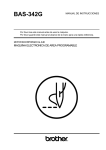
AmPlusTM 100 and AmPlus 50 Business Music Amplifiers
Installer’s Guide
Information You Should Read
English
WARNING: These business music amplifiers are electrical appliances. To reduce the
risk of fire or electric shock, do not expose the amplifier to rain or moisture; do not
disassemble the amplifier. There are no user-serviceable parts inside. Refer servicing
to qualified service personnel.
The caution markings described here appear on the top of the amplifier.
The lightning flash with arrowhead symbol, within an equilateral
triangle, signifies the presence of uninsulated dangerous voltage within
the system enclosure that may be of sufficient magnitude to constitute
a risk of electrical shock.
The exclamation point, within an equilateral triangle, as marked on the
system, signifies the presence of important operating and maintenance
instructions in this guide.
CAUTION
RISK OF ELECTRICAL SHOCK
DO NOT OPEN
CAUTION: TO REDUCE THE RISK OF ELECTRIC SHOCK,
DO NOT REMOVE COVER (OR BACK).
NO USER-SERVICEABLE PARTS INSIDE.
REFER SERVICING TO QUALIFIED PERSONNEL.
1. Read, Follow, and Save All Instructions – Read the complete safety and operating
instructions for all components before using this product. Follow all instructions.
Save the instructions for future reference.
2. Pay Attention to Warnings – Observe all warnings on the product and in this
guide.
3. Do Not Use Near Water or Moisture – Do not use this product near a bathtub,
washbowl, kitchen sink, laundry tub, in a wet basement, near a swimming pool, or
anywhere else that water or moisture is present.
4. Attachments – Do not use attachments not recommended by Bose Corporation
as they may cause hazards.
5. Maintain Proper Ventilation – To ensure reliable operation of the product and to
protect it from overheating, put the product in a position and location that will not
interfere with its proper ventilation. Do not put it in a built-in system, such as a bookcase or a cabinet, that may keep air from flowing through its ventilation openings.
6. Avoid Excessive Heat – Do not put the product near heat sources such as radiators, stoves, or other appliances that produce heat.
7. Use Proper Power Sources – Plug the product into a proper power source, as
described in the operating instructions or as marked on the product.
8. Avoid Overloading – To prevent the risk of fire or electric shock, do not overload
wall outlets, extension cords, or integral convenience receptacles.
9. Be Careful with Accessories – Mount the product only as recommended by Bose Corporation. Do not put this product on an unstable cart, stand, tripod, bracket, or table. The product may fall,
causing serious injury to a person or damage to the product. For
advice on use of a particular cart, stand, tripod, bracket, or table,
contact Bose Corporation.
If you must move your product and cart combination, do so very carefully. Quick
stops, excessive force, and uneven surfaces may cause it to overturn.
®
2
Information You Should Read
General cabling information
Connect high impedance units, such as tape players and CD players, to the amplifier
with shielded single conductor cable. Keep cable lengths shorter than 10 feet (3 m).
For output loudspeaker connections, Class II wiring is suggested. Use standard #16
AWG wire.
To minimize hum pick-up or other unwanted effects:
• Keep loudspeaker cables away from power cables.
• Use twisted shielded pairs on microphone inputs.
• Keep input cables away from:
– Loudspeaker cables to prevent inductive feedback.
– Power lines or transformers.
AWG
Wire
Diameter
(in.)
Wire
Diameter
(mm)
DCR @ 20ºC
(Ω/1000 ft.)
6
8
10
12
14
16
18
.1620
.1285
.1019
.0808
.0641
.0508
.0403
4.1
3.3
2.6
2.1
1.6
1.3
1.0
.41
.65
1.0
1.6
2.6
4.2
6.6
3
English
10. Protect the Power Cord – Route all power supply (mains) cords so that they are
not likely to be walked on or pinched. Pay particular attention to cords at plugs, at
outlets on the product, and at the point where the cord connects to the product.
11. Take Precautions against Lightning and Power Line Surges – To prevent
damage to this product during a lightning storm, or if the product will not be used
for an extended period of time, unplug its power cord from the wall outlet and
disconnect the antenna or cable system.
12. Obtain Service When It Is Indicated – The product should be serviced only by
authorized service personnel when:
A. the power supply cord or the plug has been damaged, or
B. objects have fallen or liquid has spilled into the product, or
C. the product has been exposed to rain or water, or
D. the product does not appear to operate normally or exhibits a marked change in
performance, or
E. the product has been dropped or the cabinet damaged.
13. Do not defeat the safety purpose of the polarized or grounding-type plug – A
polarized plug has two blades with one wider than the other. A grounding-type plug
has two blades and a third grounding prong. The wide blade or the third prong are
provided for your safety. When the provided plug does not fit into your outlet,
consult an electrician for replacement of the obsolete outlet.
Information You Should Read
CAUTIONS:
English
Always turn the amplifier power OFF before:
1. Connecting the speakers.
2. Changing the amplifier mode switch.
3. Installing the equalizer and/or option cards.
Never connect the speaker output channels together.
Do not connect the speaker outputs to the chassis or signal ground.
Bose® recommends installation of the amplifier be performed only by an
experienced and licensed contractor. Familiarity with standard wiring practices,
as recognized by a government agency in your area, is necessary. If you do not have
these qualifications, do not attempt to install this amplifier. Do not wall mount the
amplifier. The amplifier can be desk, shelf, or rack mounted using the rack mount
accessory kit.
Warranty period
The following products are covered by a 5-year transferable limited warranty:
• Bose AmPlusTM 100 amplifier and AmPlus 50 amplifier
• Equalizer cards
• Optional cards: Opti-voice® page and Opti-sourceTM source
Service
If you experience problems with the business music amplifier, contact your authorized Bose Professional Products dealer. The dealer will verify any defects and
arrange for service by a factory authorized Bose service agency, or by Bose Corporation. Consult your warranty card for warranty information. An owner’s registration
card is provided with this manual.
How to use this guide
This guide contains installation information on the AmPlus 100 and AmPlus 50
business music amplifiers. Each amplifier has its own section containing all information about that amplifier. Refer to the table of contents for the location of your
amplifier’s information.
The AmPlus 100 and AmPlus 50 amplifiers are each available in two versions: A 70V
constant voltage audio output version for use with 120V AC mains supply, and a 100V
constant voltage audio output version for use with 220-240V AC mains supply. This
Installer’s Guide includes instructions and specifications for both versions.
Note: Be sure to leave the AmPlus 100 Amplifier and AmPlus 50 Amplifier
Owner’s Guide with the amplifier or with the owner after completing the installation.
4
Table of Contents
Information You Should Read ................................................................................... 2
Warranty period ................................................................................................... 4
Service .................................................................................................................4
How to use this guide ......................................................................................... 4
Getting Started .......................................................................................................... 6
What you bought ................................................................................................. 6
Amplifier comparison .......................................................................................... 6
Installing the amplifier’s feet ............................................................................... 6
Removing the amplifier’s feet ............................................................................. 7
Installing the option cards ................................................................................... 7
Using the quick connectors ................................................................................ 7
Using the loudspeaker output connectors ......................................................... 7
Setting the levels ................................................................................................. 7
Installing the remote control ............................................................................... 7
All About The AmPlusTM 100 Amplifier ....................................................................... 8
AmPlus 100 amplifier controls ............................................................................ 8
AmPlus 100 Amplifier Configurations ...................................................................... 10
AmPlus 100 Amplifier Specifications ...................................................................... 15
All About The AmPlus 50 Business Music Amplifier ............................................... 16
AmPlus 50 amplifier controls ............................................................................ 16
AmPlus 50 Amplifier Configuration ......................................................................... 17
AmPlus 50 Amplifier Specifications ........................................................................18
Bose® Corporation .......................................................................... inside back cover
5
English
General cabling information ................................................................................ 3
Getting Started
The amplifier comes in one box and the accessory kit comes in another.
Figure 1
Amplifier
Declaration of
Conformity
CAUTION
AVIS
TO REDUC
DO
E THE RISK WARNING
NOT
OF FIRE OR
REFER TO EXPOSE THIS
ELECTRICAL
OPERA
YOUR INSTRU EQUIPMENT
TING PROCE
AND/O
TO
RAIN OR SHOCK,
R POOR
CTION
PERFODURES
. INCORMANUA
L FOR PROPEMOISTURE.
RMANC
RECT WIRING
E.
R INSTALLATION
MAY RESULT
IN DAMAGAND
E
Product contents
RISK OF ELECTRIC
DO NOT OPENAL SHOCK
RISQUE DE
CHOC ELECTRIQ
NE PAS
OUVRIR
UE
English
What you bought
Declarati
Bose®
on
We, the of Conformi
acknowle Corporation,
ty
offerer:
The Moun
dge MA
our 017
sole01-9
tain, Fram
Kind of
resp168
II Type designatio
onsibUSA
equipme product:
ility, that ingham,
nt: Loud
n:
in acco
the
speaker
acoustim
speaker
is in com
ce with
andrdan
direct/refass®
Artic
system
EMC Direc
plian
le 10(1
-5 serie
ce with
s
of the tive 89/3 lecting®
the) follo
documen
Technical
Directive, 36/E
EN50
Accredite
t(s): wing
081-1, regulatio
EC
norm(s)
d by Bose
EN50082ns:
or
Corporati
-1
on
ON
AmPlus™
OFF
business
100
music am
plifier
Kind of
Type designa
equipment:
tion:
Loudspeaker
speaker
acoustimass®
system
in accorda
direct/reflecti
Article
nce with
-5
10(1)
is in complia
ng®series II
Directive
of theEMC
docum
Directiv
89/336
ent(s):nce with the
e,
/EEC and
followin
EN50081-1, Technic
g norm(s
Accredited
) or
EN500 al regulations:
by Bose 82-1
Corporatio
Power cord
Remote control
Rubber feet
Warranty
card
Quick connectors
Installer’s Guide
Owner’s Guide
Amplifier comparison
This table shows the major features of the different amplifiers.
AmPlus™
AmPlus
Features
100 Amplifier 50 Amplifier
Outputs
Ch1
Ch2
70/100V (bridged)
65W
65W
100W
70W
None
50W
Inputs (balanced)
2
2
Line Outputs (balanced)
2
None
Option Cards
Paging
A/B Source switching
Yes
Yes
No
No
Installing the amplifier’s feet
The amplifier’s feet are found in the Accessories box. Use these feet if the amplifier is
being placed on a shelf, desk, counter, or any flat surface. The feet elevate the amplifier
so air circulates around and through, keeping the amplifier cool.
Note: If the amplifier is going into a rack, DO NOT mount the feet.
1
2
ON
OFF
6
AmPlus ™ 100
business music
amplifier
Getting Started
Removing the amplifier’s feet
English
Use a screwdriver to loosen the foot and pull it out.
Installing the option cards
Refer to the installation instructions that come with the equalizer card, Opti-voice®
page card, and Opti-sourceTM source card.
Using the quick connectors
The quick connectors are supplied so you can connect the amplifier to sources and
other equipment.
Figure 2
Installing a quick connector
CAUTION
RISK OF
RICAL SHOC
DO ELECT
NOT OPEN
K
RISQUE
DE CHOC
NE PAS
ELECTRIQUE
OUVR
IR
AVIS
TO RED
UCE THE
DO NOT
WARNING
EXPOSE
RISK OF
REFER
THIS EQU
FIRE OR
TO
OPERATI
ELECTRIC
IPMENT
AND/OR
NG YOUR INSTRUC
TO RAIN
AL SHO
POORPRO
CEDURE TION
OR MOIS
CK,
PERF
S. INCO MANUAL
ORMANC
TURE.
FOR PRO
E. RRECT WIRI
NG MAYPER INSTALLA
RESULT
TION AND
IN DAM
AGE
Using the loudspeaker output connectors
2
1
CAUTION
AVIS
RISK OF
DO ELECTRIC
NOT OPENAL SHOCK
RISQUE
CHOC ELECTRIQ
NEDE
PAS
OUVRIR
UE
TO REDUCE
DO
NOT
THE RISK WARNING
OF FIRE
REFER TO EXPOSE THIS
EQUIPM
OR ELECTR
OPERAT
ENT
AND/OR
ING YOUR INSTRU
ICAL SHOCK,
POORPROCED
CTION MANUA TO RAIN OR
PERFORURES.
MOISTURE.
INCORRECT L FOR
MANCE
.
WIRINGPROPER
INSTALLATION
MAY RESULT
IN DAMAGAND
E
3
CAUTION
AVIS
RISK OF
DO ELECTRIC
NOT OPENAL SHOCK
RISQUE
CHOC ELECTRIQ
NEDE
PAS
OUVRIR
UE
TO REDUCE
DO
NOT
THE RISK WARNING
OF FIRE
REFER TO EXPOSE THIS
EQUIPM
OR ELECTR
OPERAT
ENT
AND/OR
ING YOUR INSTRU
ICAL SHOCK,
POORPROCED
CTION MANUA TO RAIN OR
PERFORURES.
MOISTURE.
INCORRECT L FOR
MANCE
.
WIRINGPROPER
INSTALLATION
MAY RESULT
IN DAMAGAND
E
Setting the levels
Each input has its own level control. Use these controls to balance the relative level
of each input source. You control overall volume with the remote volume control.
Installing the remote control
The remote control should be wall mounted in an electrical box (not included) similar
to a light-switch electrical box. Install the remote control where day-to-day adjustments will be easy to make.
7
All About The AmPlusTM 100 Amplifier
English
AmPlus 100 amplifier controls
Figure 3
AmPlus 100 amplifier
controls
INPUTS A
INPUT
MODE
LEVEL
Ch1 Ch2 Zone 2
Ch1
Ch2
-6
2Ch
dual
mono mono
-10
-40 dB
+
-
+
-6
-10
REMOTE
VOLUME
ZONE 1
-6
ZONE 2
LINE OUTPUT
ZONE 1
POWER AMPLIFIER
ZONE 2
70/100V
-10
0 -40 dB 0 -40 dB 0
-
BASS
LEVEL
Ch1 Ch2
ZONE1
4-16 Ω
ZONE 2
4-16 Ω
XFR
CT
MODE
OFF +10 OFF +10
+
-
+
-
+
- +
- +
-
70/100V
2 Ch
BRIDGED
Inputs – The amplifier comes with two balanced inputs. They can be left and right
channels from a stereo source or two distinct monophonic (mono) sources for 2-zone
applications. Two mono sources can also be “mixed” for single zone applications.
Input Mode – This switch determines how the Channel 1/Channel 2 inputs are
presented to the power amplifier section of the AmPlus 100 amplifier. There are three
possible modes.
1. In the 2-Channel/Mix position, the inputs remain separate, not summed. Channel
1 and Channel 2 level potentiometers (pots) are active in this mode. Use this
mode for:
a. Stereo (2-channel).
b. Two distinct sources in a two-zone application (2-channel), one source per zone.
c. Two distinct sources in a single bridged mono zone (Mix).
Note: In Mix mode both sources, Channel 1 and Channel 2, are presented to the
amplifier simultaneously. When the internal source mix switch is in the “mix” position
(Figure 5), the Channel 1 attenuation controls the source connected to the Channel 1
input. The Channel 2 attenuation controls the source connected to the Channel 2
input.
2. Dual Mono – The Channel 1 and Channel 2 inputs are summed to mono and
presented to the amplifiers as one mono signal. This mode may also be used
when driving a 70/100V load from the Channel 1 amplifier outputs and a Bose®
Model 1B Acoustimass® module from the 4Ω Channel 2 amplifier outputs. See
“Zone 2 level adjust”.
3. Mono Mode – Both inputs, Channel 1 and Channel 2, are summed to mono. Only
the Channel 1 level pot is active.
Level – Channel 1 level adjust – In 2-channel (stereo) mode, this pot affects the signal
level at the Channel 1 low impedance (4Ω) outputs. In dual mono mode, it controls
the zone 1 level. In mono mode, it controls the level of all outputs.
Channel 2 level adjust – In 2-channel (stereo) mode, this pot controls the signal level
at the Channel 2 low impedance (4Ω) outputs. This pot is not active in dual mono or
mono modes.
Zone 2 level adjust – This pot is active only when the input mode is dual mono. In this
mode, this pot controls the signal level at the Channel 2 low impedance outputs. This
pot is a slave to the Channel 1 pot; that is, the Channel 1 pot controls the level of both
zones in a 2-zone system. However, the zone 2 pot can be used to fine-tune the level
of the second listening zone without affecting zone 1. This pot may also be used to
fine-tune the bass level when using the AmPlus 100 amplifier to drive a 70/100V load
connected to the 70/100V output and a Model 1B Acoustimass module connected to
the Channel 2 output.
8
All About The AmPlusTM 100 Amplifier
AmPlus 100 amplifier controls (cont’d)
AmPlus 100 amplifier
controls
INPUTS A
INPUT
MODE
LEVEL
Ch1 Ch2 Zone 2
Ch1
Ch2
-6
2Ch
dual
mono mono
-10
-40 dB
+
-
+
-6
-10
BASS
LEVEL
Ch1 Ch2
REMOTE
VOLUME
ZONE 1
-6
ZONE 2
LINE OUTPUT
ZONE 1
POWER AMPLIFIER
ZONE 2
70/100V
-10
0 -40 dB 0 -40 dB 0
ZONE1
4-16 Ω
ZONE 2
4-16 Ω
XFR
CT
MODE
OFF +10 OFF +10
-
+
-
+
-
+
- +
- +
-
70/100V
2 Ch
BRIDGED
Bass Level – Use the bass level potentiometers (pots) to increase the output level
between 50Hz and 150Hz. This is useful for compensating for poor bass cabinet
loading or high levels of low-frequency ambient noise. The Channel 1 and Channel 2
pots are active in all modes of operation.
Remote Volume – When using the amplifier to power one listening zone, connect the
remote control unit to the zone 1 (+) pin and the ground pin. Set the internal remote
volume switch (Figure 4) to 1_REMOTE. When using the AmPlus 100 amplifier for 2zone applications, connect a second remote to the zone 2 (+) pin and ground pin. Set
the internal remote volume switch to 2_REMOTE.
Figure 4
Internal remote volume
switch
High Pass
Filter
Mix
EQ 1
EQ 2
C
1 Remote
2 Remote
Line Outputs – Both line output responses are flat (regardless of whether or not you
have installed active equalizer cards). The remote volume control affects the line
output levels. Both outputs are active in stereo mode. Only zone 1 is active in dual
mono and mono modes.
Power Amplifier Outputs – The 70/100V output becomes active when the amp
mode switch is in the 70/100V position. In this setup, both AmPlus 100 amplifier
channels are bridged and provide up to 100W to the 70/100V speaker(s).
When the amp mode is in the 2-channel position and a jumper is placed across the
XFR CT pins, 50W is available at the 70/100V output and 65W is available at the
channel 2 output.
With the amp mode switch in the 2-channel position, both Channel 1 and Channel 2
supply 65W into a minimum load of 4Ω.
Internal High Pass Switch – When this switch is in the “HPF ON” position, frequencies below 150Hz are attenuated at 18dB/OCT. This low-frequency roll-off occurs on
Channel 1 only. Use this switch for bandlimiting high-frequency speakers connected
to Channel 1 in a bi-amplified system.
9
English
Figure 3 (cont’d)
AmPlusTM 100 Amplifier Configurations
English
AmPlus 100 Amplifier Direct-coupled Model 1B Installation
Source
Left 1
Right 1
Right 2
Left 2
Model 1B
Module
AmPlus™100 Amp
Remote
Volume
Control
INPUTS A
INPUT
MODE
LEVEL
BASS
LEVEL
Ch1 Ch2
Ch1 Ch2 Zone 2
Ch1
-6
Ch2
2Ch
dual
mono
-10
-
+
-6
ZONE 2
ZONE 1
POWER AMPLIFIER
ZONE 2
ZONE 1
4-16 Ω
70/100V
-10
OFF
0 -40 dB 0 -40 dB 0
ZONE 2
4-16 Ω
XFR
CT
MODE
+10 OFF +10
-
+
1. First, adjust Ch. 1 & 2
high frequency speaker
levels here.
L
R
Source
ZONE 1
LINE OUTPUT
mono
-40 dB
+
-6
-10
REMOTE
VOLUME
2. Then use Ch. 1 & 2
Bass pots to adjust
Bass Module level.
-
+
-
+
- +
- +
-
70/100V
BRIDGED
2 Ch.
Remote
Volume
Control
3. Internal Switch Settings
Remote Volume: 1 Remote,
Ch. 1 High Pass Filter: OFF,
2 ch./Mixer Switch: 2 ch.
Model 1B
Module
Ch. 1
Level
VCA 1
Channel 1
Input
Option Card 1
Channel 1
Mono
Dual
Mono
Input Mode Switch
section 1 of 2
2 Ch/
Mixer
Switch
Option Card 2
Channel 1
Line Outputs
EQ Card 1
Mix
Zone 2
Level
2 Ch.
Dual
Mono
ZONE 1
Mono
Input Mode Switch
section 2 of 2
ZONE 2
2 Ch.
2 Ch.
Channel 2
Input
Option Card 1
Channel 2
Option Card 2
Channel 2
EQ Card 2
VCA 2
Ch. 2
Level
70/100V Bridged
High Pass
Filter
High
Pass
Filter
Switch
Bass
Level
Ch. 1
Zone 1
Remote
Dynamic
EQ
Power Amp 2
2 Ch.
Bass Boost
+
70/100V
10
Zone 2
Remote
70/100V Bridged
Dynamic
EQ
Bass
Level
Ch. 2
1 Remote
Remote Switch
Amplifier
Mode
Switch
Bass Boost
VCA
Control 1
2 Ch.
Power Amp 1
+
ZONE 1
Power
Amplifier
Outputs
+
ZONE 2
XFR
CT
VCA
Control 2
2 Remotes
AmPlusTM 100 Amplifier Configurations
AmPlus 100 Amplifier 70/100V/Model 1B Installation
English
Source
AmPlus™ 100
Model 1B
Module
Remote
Volume
Control
INPUTS A
INPUT
MODE
LEVEL
BASS
LEVEL
Ch1 Ch2 Zone 2
Ch1
-6
Ch2
2Ch
dual
mono
-10
-6
-10
-
+
REMOTE
VOLUME
LINE OUTPUT
POWER AMPLIFIER
Ch2
-6
ZONE 1
ZONE 2
ZONE 1
ZONE 2
70/100V
ZONE 1
4-16 Ω
-10
ZONE 2
4-16 Ω
XFR
CT
MODE
mono
-40 dB 0 -40 dB 0 -40 dB
+
Ch1
0
OFF
+10 OFF
+10
-
+
-
+
-
+
- +
- +
-
70/100V
BRIDGED
2-CH
Use jumper
1. First, adjust high
frequency speaker
level here.
Source
L
R
2. Then use Zone 2 and
Ch. 2 Bass pots to adjust
Bass Module level.
Remote
Volume
Control
3. Internal Switch Settings
Remote Volume: 1 Remote,
Ch. 1 High Pass Filter: ON,
2 Ch./Mixer Switch: 2 Ch.
Tap settings,
less than or
equal to 50W
Model 1B
Module
Ch. 1
Level
VCA 1
Channel 1
Input
Option Card 1
Channel 1
Mono
Dual
Mono
Input Mode
Switch section
1 of 2
Channel 2
Input
2 Ch.
2 Ch/
Mixer
Switch
Option Card 2
Channel 1
Line Outputs
EQ Card 1
Mix
Zone 2
Level
2 Ch.
Option Card 1
Channel 2
Dual
Mono
ZONE 1
Mono
Input Mode
Switch Section 2 of 2
ZONE 2
2 Ch.
Option Card 2
Channel 2
EQ Card 2
VCA 2
Ch. 2
Level
High
Pass
Filter
Switch
70/100V Bridged
High Pass
Filter
Zone 1
Remote
Dynamic
EQ
Bass
Level
Ch. 1
Bass Boost
1 Remote
Remote Switch
Amplifier
Mode
Switch
Power Amp 2
Zone 2
Remote
70/100V Bridged
Dynamic
EQ
Bass
Level
Ch. 2
VCA
Control 1
2 Ch.
Power Amp 1
VCA
Control 2
2 Remotes
2 Ch.
Power
Amplifier
Outputs
Bass Boost
+
70/100V
+
ZONE 1
+
ZONE 2
XFR
CT
11
AmPlusTM 100 Amplifier Configurations
English
AmPlus 100 Amplifier Simple Monophonic Installation
Source
AmPlus™ 100
Remote
Volume
Control
INPUTS A
INPUT
MODE
LEVEL
Ch1
Ch1
Ch2
dual
mono
-10
-
+
-6
-10
-6
ZONE 1
ZONE 2
ZONE 1
POWER AMPLIFIER
ZONE 2
70/100V
0 -40 dB
0 -40 dB
0
OFF
+10 OFF
+
-
+ -
Remote
Volume
Control
XFR
CT
MODE
+
- +
- +
-
70/100V
2 Ch.
BRIDGED
Tap settings
less than or
equal to 100W
Note: Both bass pots are active
in this mode. Use both of these
controls to make bass level
adjustments.
R
ZONE 2
4-16 Ω
+10
-
L
ZONE 1
4-16 Ω
-10
Internal Switch Settings
Remote Volume: 1 Remote,
Ch. 1 High Pass Filter: OFF,
2 Ch./Mixer Switch: 2 Ch.
Source
LINE OUTPUT
mono
-40 dB
+
Ch2 Zone 2
-6
2Ch
REMOTE
VOLUME
BASS
LEVEL
Ch1 Ch2
Ch. 1
Level
VCA 1
Channel 1
Input
Option Card 1
Channel 1
Option Card 2
Channel 1
Line Outputs
EQ Card 1
Mono
Dual
Mono
Input Mode Switch
section 1 of 2
2 Ch/
Mixer
Switch
Mix
Zone 2
Level
2 Ch.
Dual
Mono
ZONE 1
Mono
Input Mode Switch
section 2 of 2
ZONE 2
2 Ch.
2 Ch.
Channel 2
Input
Option Card 1
Channel 2
Option Card 2
Channel 2
EQ Card 2
VCA 2
Ch. 2
Level
70/100V Bridged
High Pass
Filter
High
Pass
Filter
Switch
Bass
Level
Ch. 1
Zone 1
Remote
Power Amp 1
Remote Switch
Amplifier
Mode
Switch
Power Amp 2
2 Ch.
Bass Boost
+
70/100V
12
Zone 2
Remote
70/100V Bridged
Dynamic
EQ
Bass
Level
Ch. 2
1 Remote
2 Ch.
Dynamic
EQ
Bass Boost
VCA
Control 1
+
ZONE 1
Power
Amplifier
Outputs
+
ZONE 2
XFR
CT
VCA
Control 2
2 Remotes
AmPlusTM 100 Amplifier Configurations
AmPlus 100 Amplifier Large Monophonic Installation
English
Source 1
Source 2
AmPlus™ 100
Remote
Volume
Control
AmPlus™ 100
INPUTS A
INPUT
MODE
LEVEL
BASS
LEVEL
Ch1 Ch2
Ch1 Ch2 Zone 2
Ch1
Ch2
-6
dual
mono
2Ch
-
+
-10
-6
ZONE 1
LINE OUTPUT
ZONE 2
0 -40 dB
0 -40 dB
OFF
0
+10 OFF
70/100V
ZONE 2
4-16 Ω
ZONE 1
4-16 Ω
XFR
CT
MODE
+10
+
1. Adjust the source 1
level with the ch. 1 pot.
-
+ -
+
- +
- +
-
70/100V 2 Ch.
BRIDGED
Tap settings
less than or
equal to
100W
2. Adjust the source 2
level with the ch. 2 pot.
3. Internal Switch Settings
Remote Volume: 1 Remote,
Ch. 1 High Pass Filter: OFF,
2 Ch./Mixer Switch: Mixer position
Note: Both bass pots are active in
this mode. Use both of these
controls to adjust bass level.
Source 2
ZONE 2
ZONE 1
-10
-
Source 1
POWER AMPLIFIER
mono
-40 dB
+
-6
-10
REMOTE
VOLUME
Tap settings
less than or
equal to
100W
Aux Amp 1
Remote
Volume
Control
Source 1
Level
VCA 1
Mono
Source 1
Input
Option Card 1
Channel 1
Mono
Dual
Mono
Input Mode Switch
section 1 of 2
2 Ch/
Mixer
Switch
Option Card 2
Channel 1
Line Outputs
EQ Card 1
Dual
Mono
Mix
Zone 2
Level
2 Ch.
Mono
ZONE 1
Input Mode Switch
section 2 of 2
ZONE 2
2 Ch.
Mono
Source 2
Input
2 Ch.
Option Card 1
Channel 2
Option Card 2
Channel 2
EQ Card 2
VCA 2
Source 2
Level
70/100V Bridged
High Pass
Filter
High
Pass
Filter
Switch
Bass
Level
Ch. 1
Zone 1
Remote
Power Amp 1
Dynamic
EQ
Bass Boost
1 Remote
Remote Switch
Amplifier
Mode
Switch
Zone 2
Remote
Power Amp 2
VCA
Control 2
2 Remotes
70/100V Bridged
Dynamic
EQ
Bass
Level
Ch. 2
VCA
Control 1
2 Ch.
2 Ch.
Bass Boost
+
70/100V
+
ZONE 1
Power
Amplifier
Outputs
+
ZONE 2
XFR
CT
13
AmPlusTM 100 Amplifier Configurations
English
AmPlus 100 Amplifier With Two 70/100V Zones Installation
Source
Zone 1
Remote
Volume
Control
AmPlus™ 100
Zone 2
Remote
Volume
Control
Accessory 70/100V
Transformer
INPUTS A
INPUT
MODE
LEVEL
Ch1 Ch2 Zone 2
Ch1
Ch2
-6
2Ch
-10
dual
mono mono
-6
-
+
REMOTE
VOLUME
-6
-10
ZONE 1
LINE OUTPUT
ZONE 2
ZONE 1
POWER AMPLIFIER
ZONE 2
70/100V
-10
-40 dB 0 -40 dB 0 -40 dB 0
+
BASS
LEVEL
Ch1 Ch2
ZONE 1
4-16 Ω
ZONE 2
4-16 Ω
XFR
CT
MODE
OFF +10 OFF +10
-
+
-
+
-
+
- +
- +
-
70/100V
2 Ch.
BRIDGED
Use jumper
1. First, adjust the
Zone 1 listening level.
Source
2. Then use the Zone 2
pot to adjust the Zone 2
listening level.
L
R
Zone 1
Remote
Volume
Control
Zone 2
Remote
Volume
Control
Accy.
70/100V
XFR
3. Internal Switch Settings
Remote Volume: 2 Remotes,
Ch. 1 High Pass Filter: OFF,
2 Ch./Mixer Switch: 2 Ch.
Tap settings: less than
or equal to 50 Watts
per channel
Ch. 1
Level
VCA 1
Channel 1
Input
Option Card 1
Channel 1
Mono
Dual
Mono
Input Mode Switch
section 1 of 2
Option Card 2
Channel 1
Dual
Mono
Mix
2 Ch/
Mixer
Switch
Line Outputs
EQ Card 1
Mono
Zone 2
Level
2 Ch.
ZONE 1
Input Mode Switch
section 2 of 2
ZONE 2
2 Ch.
Channel 2
Input
2 Ch.
Option Card 1
Channel 2
Option Card 2
Channel 2
EQ Card 2
VCA 2
Ch. 2
Level
High
Pass
Filter
Switch
Power Amp 1
2 Ch.
Dynamic
EQ
Bass
Level
Ch. 1
Bass Boost
Power Amp 2
Zone 2
Remote
Volume
Control
70/100V Bridged
2 Ch.
Bass Boost
+
70V
14
VCA
Control 1
1 Remote
Remote Switch
Amplifier
Mode
Switch
Dynamic
EQ
Bass
Level
Ch. 2
Zone 1
Remote
Volume
Control
70/100V Bridged
High Pass
Filter
+
ZONE 1
Power
Amplifier
Outputs
+ ZONE
2
XFR
CT
TO ZONE 2
70/100V Accessory
Transformer
VCA
Control 2
2 Remotes
AmPlusTM 100 Amplifier Specifications
Power output
Input sensitivity
315mV required to drive both channels
to full power in any mode
Input attenuation
0dB to off
Input/Output configurations
1. 2-channel (stereo)
2. Mono into 4Ω load
3. Mono into 70/100V load
4. Dual-Mono (1 source/2 zones)
5. 2-channel (70/100V and 4Ω/Ch2)
Input impedance
32kΩ balanced
11kΩ unbalanced
Line output impedance
600Ω
Line output distortion
≤0.1%
Frequency response
(active EQ bypassed)
4Ω outputs: 40Hz – 16kHz, ±1dB
70/100V outputs: 60Hz – 16kHz, ±1dB
THD @ rated power
4Ω outputs: ≤1% THD (40Hz – 16kHz)
70/100V outputs: ≤1% THD
(60Hz – 16kHz)
Hum and noise
Line outputs: 92dB
Pwr amp outputs: 80dB below maximum
output with 4Ω load
Controls
Inputs 1 and 2, input attenuation,
remote volume, bass adjust 1 and 2.
Input mode and amplifier mode switches.
LED indicator
Power: front panel
English
Stereo: 65W per channel into 4Ω
50W into 8Ω
70V bridged mono: 100W into 49Ω
100V bridged mono: 100W into 98Ω
70V/4Ω: 50W @70V output into 98Ω
65W @Ch2 output into 4Ω
100V/4Ω: 50W @70V output into 196Ω
65W @Ch2 output into 4Ω
AC power consumption
120V~AC, 50/60Hz, 350W max
220-240V~AC, 50/60Hz, 350W max
Operating temperature range
(passively cooled, top and
bottom vents)
12º F to 120º F (-10º C to +50º C)
Special features
Remote volume control
Turn on/off muting
Clip detection and limiter
Short circuit protection
DC offset protection
Thermal limiting
Stable into reactive loads
RFI protection
International safety approvals under
UL-6500, CSA-E65, IEC-65
EMC CE compliance
Option card accessories
EQ cards (Model 8 loudspeaker, Model
25 loudspeaker, Model 32 loudspeaker,
and Model 1B Acoustimass® module,
402TM loudspeaker, 502® loudspeaker,
802® loudspeaker)
Opti-SourceTM card
Opti-voice® page card
Terminations
Inputs and outputs are quick
connect terminal blocks
Size
17"W x 10"D x 33⁄4"H
(43.2 x 25.4 x 9.5 cm)
(desk mount)
19"W x 10"D x 33⁄4"H
(48.3 x 25.4 x 9.5 cm)
(rack mount, chassis supported)
Weight
20 lb (9.1 kg)
Associated equipment
Rack mount kit
70/100V transformer
Front panel power switch.
15
All About The AmPlusTM 50 Amplifier
English
AmPlus 50 amplifier controls
Figure 5
INPUTS A
LEVEL
BASS
GAIN
REMOTE
VOLUME
POWER AMPLIFIER
Ch1 Ch2
AmPlus 50 amplifier controls
Ch1
-6
Ch2
-10
-6
70/100V
-40 dB 0 -40 dB 0
+
-
+
4-16 Ω
MODE
-10
OFF +10
-
+
- +
-
70/100V
4-16 Ω
Inputs – The AmPlus 50 amplifier comes with two balanced inputs. They can be left
and right from a stereo source; two mono sources can also be mixed. Since the
AmPlus 50 amplifier is a single channel amplifier, a stereo source is internally summed
to mono.
Level – Channel 1 level adjust – This potentiometer (pot) controls the signal level of the
Channel 1 input source.
Channel 2 level adjust – This pot controls the signal level of the Channel 2 input
source.
Bass Gain – Use the bass gain pot to increase the output level between 50Hz and
150Hz (affects 50Hz – 150Hz only). This is useful for compensating for poor bass
cabinet loading or high levels of low-frequency ambient noise.
Remote Volume – Connect the remote control unit to the zone 1 (+) pin and the
ground pin.
Figure 6
Internal remote volume
switch
High Pass
Filter
EQ 1
C
Power Amplifier Outputs – The 70/100V output is active when the amplifier Mode
Switch is in the 70/100V position. The 4Ω output is active when the amplifier Mode
Switch is in the 4Ω position.
Internal High Pass Switch – When this switch is in the “HPF ON” position, frequencies below 150Hz are attenuated at 18dB/OCT. Use this switch for band-limiting highfrequency speakers in a bi-amplified system.
16
AmPlusTM 50 Amplifier Configuration
AmPlus 50 Amplifier Simple Monophonic Installation
English
Source
AmPlus™ 50
Remote
Volume
Control
INPUTS A
Ch1
LEVEL
-6
Ch2
-10
BASS
GAIN
REMOTE
VOLUME
POWER AMPLIFIER
-6
70/100V
4-16 Ω
MODE
-10
-40 dB
0 -40 dB
0
OFF
+10
Ch1 Ch2
+
-
Source
+
-
+
Internal Switch Settings:
High Pass Filter: OFF
-
70/100V
4-16 Ω
Tap settings:
less than or
equal to 50W
Remote
Volume
Control
L
R
- +
Ch. 1
Level
Channel 1
Input
EQ Card
VCA
Channel 2
Input
Ch. 2
Level
4-16 Ω
High Pass
Filter
High
Pass
Filter
Switch
Remote
70/100V
Power Amp 1
VCA
Control
Dynamic
EQ
Amplifier
Mode
Switch
Bass
Gain
Bass Boost
4-16 Ω
70/100V
Power
Amplifier
Outputs
+
70/100V
+
4-16 Ω
17
AmPlus™ 50 Amplifier Specifications
Power output
English
70V mono: 50W into 98Ω
100V mono: 50W into 196Ω
4Ω mode: 70W into 4Ω
Input sensitivity
315mV required to drive both channels
to full power in any mode
Input attenuation
0dB to -∞
Input/Output configurations
1. Mono into 4Ω load
2. Mono into 70/100V load
3. As an extension to the
AmPlus 100 amplifier
Input impedance
32kΩ balanced
11kΩ unbalanced
Line output impedance
600Ω
Line output distortion
≤0.1%
Frequency response
(active EQ bypassed)
4Ω outputs: 40Hz – 16kHz, ±1dB
70/100V outputs: 60Hz – 16kHz, ±1dB
THD @ rated power
4Ω outputs: ≤1% THD (40Hz – 16kHz)
70/100V outputs: ≤1% THD
(60Hz – 16kHz)
Hum and noise
Power amplifier outputs: 80dB below
maximum output with 4Ω load
Controls
Inputs 1 and 2, input attenuation, remote
volume, bass adjust effects bandwidth of
50Hz – 150Hz by 0 – 10dB.
Amplifier mode switch.
Front panel power switch.
18
LED indicators
Power: front panel
AC power consumption
120V~AC, 50/60Hz, 200W max
220-240V~AC, 50/60Hz, 200W max
Operating temperature range
(passively cooled, top and
bottom vents)
12º F to 120º F (-10º C to +50º C)
Special features
Remote volume control
Turn on/off muting
Clip detection and limiter
Short circuit protection
DC offset protection
Thermal limiting
Stable into reactive loads
RFI protection
International safety approvals under
UL-6500, CSA-E65, IEC-65
EMC CE compliance
Option card accessories
EQ cards: (Model 8 loudspeaker,
Model 25 loudspeaker, Model 32
loudspeaker, Model 1B Acoustimass®
module)
Terminations
Inputs and outputs are quick connect
terminal blocks
Size
17"W x 10"D x 33⁄4"H
(43.2 x 25.4 x 9.5 cm)
(desk mount)
19"W x 10"D x 33⁄4"H
(48.3 x 25.4 x 9.5 cm)
(rack mount, chassis supported)
Weight
20 lb (9.1 kg)
Associated equipment
Rack mount kit
Bose® Corporation
USA
Canada
Bose Ltd., 1-35 East Beaver Creek Road
Richmond Hill, Ontario L4B 1B3
1-800-444-BOSE (1-800-444-2673)
Phone hours – ET (eastern time):
Weekdays 9 a.m. to 5 p.m. ET
European Office
Bose B.V., Nijverheidstraat 8
1135 GE Edam, Nederland
TEL 0299-390139
FAX 0299-390109
Australia
Bose Australia, Inc., 1 Sorrell Street
Parramatta, N.S.W. 2150
TEL 02 204-6111
FAX 02 204-6122
Belgique/België
Bose N.V., Limesweg 2, B-3700 Tongeren
TEL 012-390800
FAX 012-390840
Danmark
Bose A/S, Industrivej 7, 2605 Brøndby
TEL 4343-7777
FAX 4343-7818
Deutschland
Bose GmbH, Max-Planck-Straße 36d
D-61381 Friedrichsdorf
TEL 06172-71040
FAX 06172-710419
France
Bose S.A., 6, rue Saint Vincent
78100 Saint Germain en Laye
TEL 01-3061-6363 FAX 01-3061-4105
India
Bose Corporation India Private Limited
W-16, Greater Kailash-II
New Delhi 110 048
TEL (011) 648-4462 FAX (011) 648-4463
Ireland
Bose Corporation
Carrickmacross, Co Monaghan
TEL 042-61988
FAX 042-61998
Italia
English
Bose Corporation, The Mountain
Framingham, MA 01701-9168
1-800-288-BOSE (1-800-288-2673)
Phone hours – ET (eastern time):
Weekdays 9 a.m. to 8 p.m.
Saturdays 9 a.m. to 3 p.m.
Bose S.p.A., Via Luigi Capucci, 12
00147 Roma
TEL 06-5127641
FAX 06-5115438
Japan
Bose K.K., Shibuya YT Building
28-3 Maruyama-cho
Shibuya-ku, Tokyo 150
TEL 3-5489-1054
FAX 3-5489-0591
Nederland
Bose B.V., Nijverheidstraat 8
1135 GE Edam
TEL 0299-390139
FAX 0299-390109
Norge
Bose A/S, Solheimsgate 11
N-2001, Lillestrøm
TEL 63-817380
FAX 63-810819
Österreich
Bose Ges.m.b.H., Vienna Business Park
Wienerbergstrasse 7 (10.OG)
A-1100 Vienna
TEL 01-60404340
FAX 01-604043423
Schweiz/Suisse
Bose AG, Rünenbergerstrasse 13
4460-Gelterkinden
TEL 061-9815544
FAX 061-9815502
Sverige
Bose A/S, Blandsädsgatan 2D
S-43146 Mölndal
TEL 031-878850
FAX 031-274891
United Kingdom
Bose Limited, Unit G2
Trinity Trading Estate
Sittingbourne, Kent ME10 2PD
TEL 01795-475341 FAX 01795-427227
From other locations
Bose Customer Service, 1 New York Avenue
Framingham, MA 01701-9168 USA
TEL (508)766-1900 FAX (508)766-1919
World Wide Web
www.bose.com
19
©1998 Bose Corporation, The Mountain, Framingham, MA 01701-9168 USA
JN97810 English