1
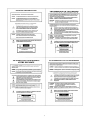
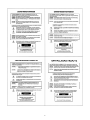
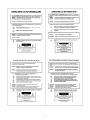
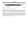
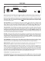
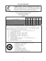
MPA250
Multi-Purpose Amplifier
Operation Manual
Biamp Systems | 9300 S.W. Gemini Drive | Beaverton, OR | 97008 | USA | +1.503.641.7287 | www.biamp.com
MPA250
TABLE OF CONTENTS
Safety Information
INTRODUCTION
pgs. 2~5
Front Panel
pg. 6
Rear Panel
pg. 7
Specifications
pg. 8
Warranty
pg. 9
MPA250 single-channel, multi-purpose amplifiers deliver a full 250 Watts of power into
direct or distributed speaker systems. The MPA250 is designed for reliable service in
permanent installations, and comes complete with short-circuit and thermal protection,
including front/rear panel indicators and automatic reset. Plug-in barrier strip input and
screw terminal outputs provide trouble-free, dependable connections. MPA250
amplifiers are UL listed and carry Biamp's five-year warranty.
MPA250 features include:
♦ 250 watts at all outputs (4 ohm direct & transformer)
♦ internal transformer (8 ohm, 70V, 25V, & 25V-CT outputs)
♦ signal/peak & temp/fault indicators on front & rear panels
♦ balanced/unbalanced input selector on rear panel
♦ level control & input sensitivity selector on rear panel
♦ high-pass filter selector on rear panel (12dB/oct. @ 125Hz)
♦ input on plug-in barrier - outputs on screw terminals
♦ complete speaker, short-circuit, & thermal protection
♦ variable speed fan (quiet, reliable - no filter maintenance)
♦ incorporates AES recommended grounding practices
♦ covered by Biamp Systems' five-year warranty
♦ UL / C-UL listed
1
IMPORTANT SAFETY INSTRUCTIONS
Read these instructions.
Do not install near any heat sources such as
radiators, heat registers, stoves, or other apparatus
(including amplifiers) that produce heat.
Keep these instructions.
Heed all warnings.
Do not defeat the safety purpose of the polarized or
grounding-type plug. A polarized plug has two
blades with one wider than the other. A grounding
type plug has two blades and a third grounding
prong. The wide blade or the third prong are
provided for your safety. When the provided plug
does not fit into your outlet, consult an electrician
for replacement of the obsolete outlet.
Follow all instructions.
Do not use this apparatus near water.
Clean only with a dry cloth.
Do not block any of the ventilation openings.
Protect the power cord from being walked on or
pinched particularly at plugs, convenience
receptacles, and the point where they exit from the
apparatus.
Install in accordance with the manufacturers
instructions.
WARNING - To reduce the risk of electric shock, do
not expose this apparatus to rain or moisture.
Refer all servicing to qualified service personnel.
Servicing is required when the apparatus has been
damaged in any way, such as power-supply cord
or plug is damaged, liquid has been spilled or
objects have fallen into the apparatus, the
apparatus has been exposed to rain or moisture,
does not operate normally, or has been dropped.
The apparatus shall not be exposed to dripping or
splashing and no objects, such as vases, shall be
placed on the apparatus.
Unplug this apparatus during lightning storms or
when unused for long periods of time.
Use only attachments/accessories specified by the manufacturer.
Use only with the cart, stand, tripod, bracket, or table specified by the manufacturer or sold with the apparatus.
When a cart is used, use caution when moving the cart/apparatus combination to avoid injury from tip-over.
Unplug this apparatus during lightning storms or when unused for long periods of time.
The appliance inlet shall be readily operable once installed.
WARNING - Terminals marked with the following symbol are Hazardous. Connections to these teminals must be
made by qualified personnel.
2
3
4
5
FRONT PANEL
On Indicator: This green LED remains lit when AC power is applied to the unit.
Signal / Peak Indicator: This 2-color LED indicates the signal level for the amplifier. When the LED is green, the amplifier has signal
(above -30dB). When the LED is red, the amplifier signal is clipping (max. power). CAUTION: Signal levels should be adjusted to avoid
clipping. Clipping can cause severe distortion, over-temperature conditions, and even loudspeaker damage. NOTE: Signal / Peak
indicators will turn off during Temp / Fault conditions (see Temp / Fault Indicators below). This indicator also appears on the rear panel.
Temp / Fault Indicator: This red LED indicates over-temperature and output fault conditions for the amplifier. When the LED remains lit,
the amplifier has an over-temperature condition. When the LED is flashing, the amplifier has an output fault condition. Either condition will
temporarily de-activate the amplifier, causing the Signal / Peak LED to turn off as well. The amplifier will attempt to self-reset once the
over-temperature or output fault condition is resolved. This indicator also appears on the rear panel. CAUTION: The MPA250 is cooled
by a variable speed fan, which exhausts warm air from the left side panel. To allow proper ventilation, an un-obstructed clearance of at
least 0.75" must be maintained along the left side panel of the MPA250.
6
REAR PANEL
WARNING: SHOCK HAZARD - DO NOT OPEN
NO USER SERVICEABLE PARTS INSIDE. REFER
SERVICING TO QUALIFIED SERVICE PERSONNEL.
TO REDUCE THE RISK OF FIRE OR ELECTRICAL SHOCK,
DO NOT EXPOSE THIS APPLIANCE TO RAIN OR MOISTURE.
52SJ
AVIS: RISQUE DE CHOC ÉLECTRIQUE - NE PAS OUVRIR
US
E215636
MPA250
BIAMP SYSTEMS
Designed in Oregon, U.S.A.
Assembled in India
CAUTION
I
Class 2 Wiring
direct
output
xfmr output
UNBAL
775mV
OFF
CAUTION:
Risk of fire replace fuse only
with same type
T 6.3 A L 250 V
RISK OF ELECTRICAL SHOCK.
DO NOT OPEN.
Use only with a 250V fuse
Employer uniquement avec
un fusible de 250V
~120V 60Hz 900 Watts
signal / peak
R
temp / fault
UL
LISTED
level
O
8Ω
70V
25V
25V
CT
COM
OUT
XFMR
INPUT
4Ω
GND
BAL
300mV
HPF
C
input
Input: This plug-in barrier strip provides the line-level input to the amplifier. For unbalanced input, wire high (+) and ground (d). For
balanced input, wire high (+), low (-), and ground (d). NOTE: The UNBAL / BAL switch must be in the appropriate position (see below).
Level: This screw-driver adjustable control determines the level of input signals allowed into the amplifier. Level provides a gain range
from 'off' (min.) to 'unity' (max.). The Level control is factory set for -20dB of gain, which will produce maximum output power with input
signal peaks of +20dBu. For best performance, first adjust the source signals for optimum (maximum) levels, then adjust the amplifier
Level control for the desired volume.
Signal / Peak Indicator: This 2-color LED indicates the signal level for the amplifier. When the LED is green, the amplifier has signal
(above -30dB). When the LED is red, the amplifier signal is clipping (max. power). CAUTION: Signal levels should be adjusted to avoid
clipping. Clipping can cause severe distortion, over-temperature conditions, and even loudspeaker damage. NOTE: Signal / Peak
indicators will turn off during Temp / Fault conditions (see Temp / Fault Indicators below). This indicator also appears on the front panel.
Temp / Fault Indicator: This red LED indicates over-temperature and output fault conditions for the amplifier. When the LED remains lit,
the amplifier has an over-temperature condition. When the LED is flashing, the amplifier has an output fault condition. Either condition will
temporarily de-activate the amplifier, causing the Signal / Peak LED to turn off as well. The amplifier will attempt to self-reset once the
over-temperature or output fault condition is resolved. This indicator also appears on the front panel. CAUTION: The MPA250 is cooled
by a variable speed fan, which exhausts warm air from the left side panel. To allow proper ventilation, an un-obstructed clearance of at
least 0.75" must be maintained along the left side panel of the MPA250.
HPF Switch: This DIP switch provides a High-Pass Filter for the amplifier input. The High-Pass Filter is used to eliminate unnecessary
lower frequencies (12dB/octave @ 125Hz) for speech and distributed speaker applications. From the factory, the High-Pass Filter is
enabled (switch down). To disable the High-Pass Filter, move the switch to the up position. CAUTION: To avoid output fault conditions,
the High-Pass Filter must be enabled when driving 25/70 Volt speaker systems (see Output below). Also, any other system equalization
affecting frequencies below 125 Hz should remain flat or be used as cut-only.
775mV / 300mV Switch: This DIP switch selects 0.775Vrms (0dBu) or 0.3Vrms (-8dBu) as input sensitivity for the amplifier. From the
factory, input sensitivity is set for 775mV (switch up). Use the 775mV setting for 'professional' line-level input signals (such as from an
audio mixer or processor), or use the 300mV setting for 'consumer' line-level signals (such as from a CD player or tape deck).
UNBAL / BAL Switch: This DIP switch selects unbalanced or balanced input connection. From the factory, input connection is set for
UNBAL (switch up). Use UNBAL for 2-conductor connections, and use BAL for 3-wire connections (see Input above).
Output: These screw terminals provide the speaker outputs from the amplifier. From the factory, a jumper wire is installed from the 4Ω
terminal (direct output) to the XFMR INPUT terminal. For transformer (xfmr) output, connect speaker negative to the COM OUT terminal,
and connect speaker positive to the appropriate transformer output terminal (8Ω for an 8 ohm speaker load; 70V for a 70 Volt distributed
speaker system; 25V for a 25 Volt distributed speaker system). For 'balanced' 25V speaker systems, connections are the same as above,
plus a ground connection (center-tap) made to the 25V CT terminal. For direct output from the amplifier, first remove the factory installed
jumper wire, then connect speaker negative to the GND terminal, and connect speaker positive to the 4Ω terminal.
AC Power Switch: The switch applies AC power to the unit.
AC Fuse & Power Cord: Replace Fuse with same type and value only (6.3 A 250 V). NOTE: If the Fuse continues to blow, the amplifier
may require service. The receptacle accepts the detachable AC Power Cord. The AC Power Cord is for connection to three-prong
grounded AC outlets. CAUTION: Do not remove or defeat the ground prong on the AC Power Cord, as this constitutes a shock hazard.
7
SPECIFICATIONS
Continuous Power (4 ohm direct & transformer outputs):
250 watts
Signal-to-Noise Ratio (20Hz~20kHz):
referenced to 250 watts into 4 ohm direct output
> 90dB
Total Harmonic Distortion:
20Hz~20kHz @ 250 watts into 4 ohm direct output
< 0.2%
100Hz~15kHz @ 250 watts at transformer outputs
< 1.0%
Intermodulation Distortion (SMPTE):
< 0.35%
Frequency Response (20Hz~20kHz):
+0/-1dB
Input Impedance:
balanced
20k ohms
unbalanced
10k ohms
Input Sensitivity (selectable):
775mV / 300mV
Power Requirements:
120VAC @ 60Hz
Power Consumption:
900 watts
Dimensions (H x W x D):
3.5" x 19" x 8.5" (89 x 483 x 216mm)
Weight:
23 lbs. (10.5kg)
8
WARRANTY
BIAMP SYSTEMS IS PLEASED TO EXTEND THE FOLLOWING 5-YEAR LIMITED WARRANTY TO THE
ORIGINAL PURCHASER OF THE PROFESSIONAL SOUND EQUIPMENT DESCRIBED IN THIS MANUAL
1. BIAMP Systems warrants to the original purchaser of new
products that the product will be free from defects in material
and workmanship for a period of 5 YEARS from the date of
purchase from an authorized BIAMP Systems dealer, subject to
the terms and conditions set forth below.
5.
THIS WARRANTY IS IN LIEU OF ALL OTHER
WARRANTIES, EXPRESS OR IMPLIED. BIAMP SYSTEMS
DISCLAIMS ALL OTHER WARRANTIES, EXPRESS OR
IMPLIED, INCLUDING, BUT NOT LIMITED TO, IMPLIED
WARRANTIES OF MERCHANTABILITY AND FITNESS FOR A
PARTICULAR PURPOSE.
2. If you notify BIAMP during the warranty period that a BIAMP
Systems product fails to comply with the warranty, BIAMP
Systems will repair or replace, at BIAMP Systems' option, the
nonconforming product. As a condition to receiving the benefits
of this warranty, you must provide BIAMP Systems with
documentation that establishes that you were the original
purchaser of the products. Such evidence may consist of your
sales receipt from an authorized BIAMP Systems dealer.
Transportation and insurance charges to and from the BIAMP
Systems factory for warranty service shall be your responsibility.
6. The remedies set forth herein shall be the purchaser's sole
and exclusive remedies with respect to any defective product.
7. No agent, employee, distributor or dealer of Biamp Systems
is authorized to modify this warranty or to make additional
warranties on behalf of Biamp Systems.
statements,
representations or warranties made by any dealer do not
constitute warranties by Biamp Systems. Biamp Systems shall
not be responsible or liable for any statement, representation or
warranty made by any dealer or other person.
3. This warranty will be VOID if the serial number has been
removed or defaced; or if the product has been altered,
subjected to damage, abuse or rental usage, repaired by any
person not authorized by BIAMP Systems to make repairs; or
installed in any manner that does not comply with BIAMP
Systems' recommendations.
8. No action for breach of this warranty may be commenced
more than one year after the expiration of this warranty.
9. BIAMP SYSTEMS SHALL NOT BE LIABLE FOR SPECIAL,
INDIRECT, INCIDENTAL, OR CONSEQUENTIAL DAMAGES,
INCLUDING LOST PROFITS OR LOSS OF USE ARISING
OUT OF THE PURCHASE, SALE, OR USE OF THE
PRODUCTS, EVEN IF BIAMP SYSTEMS WAS ADVISED OF
THE POSSIBILITY OF SUCH DAMAGES.
4. Electro-mechanical fans, electrolytic capacitors, and normal
wear and tear of items such as paint, knobs, handles, and
covers are not covered under this warranty.
Biamp Systems
9300 S.W. Gemini Drive
Beaverton, Oregon 97008
(503) 641-7287
585.0174.90A
9
EU RoHS COMPLIANT
This Biamp product, including all attendant cables and accessories
supplied by Biamp, meets all requirements of EU Directives
2002/95/EC of January 27, 2003, and 2005/618/EC of August 18,
2005, the EU RoHS Directives. An EU RoHS Materials Content
Declaration document may be obtained at www.biamp.com
(This information is presented to comply with the requirements of Chinese law SJ/T11363-2006)
有害物质表 (Hazardous Substances Table)
Biamp Systems Corporation
音频放大器 (Audio Amplifier)
MPA250
部件名称 (Part Name)
设备机箱 (Equipment Chassis) 电源线 (Power Cord)
插拔式接线端子 (Plug-in Terminal Blocks)
手册和其他书面文档 (Manual and Paper Documents)
包装箱和所有包装材料 (Box and Packing Materials)
Pb
铅
X
O
O
O
O
有毒有害物质或元素 (Substances)
Hg
Cd
Cr+6
PBB PBDE
汞
镉
六价铬
O
X
O
O
O
O
O
O
O
O
O
O
O
O
O
O
O
O
O
O
O
O
O
O
O
0:表示该部件所有均质材料中的这种有毒有害物质低于 SJ/T11363-2006 的限制要求.
X:表示该部件中至少有一种均质材料所含的这种有毒有害物质高于 SJ/T11363-2006 的限制要求.
在电触头和(或)镀镉所含的均质材料中,镉及其化合物的含量可以超过 0.01%,但欧盟指令 91/338/EEC(根据欧盟指令
76/769/EEC)限制销售和使用某些危险物质和制剂部分中所禁止的用途除外
在以下一种或多种物质所含的均质材料中,铅及其化合物的含量可以超过 0.1%:
1) 电子元器件中玻璃内所含的铅
2) 铅在钢材中是作为一种合金元素,含量可达 0.35%
3) 铅在铝材中是作为一种合金元素,含量可达 0.4%
4) 铅在铜材中是作为一种合金元素,含量可达 4%
5) 高熔点类焊料中的铅(即铅料合金,铅含量超过 85%)
6) 电子陶瓷部件内的铅
7) 由两种以上元素组成的焊料中所含的铅,用于连接针脚和微处理器包装,其中
铅的含量超过 80% 但低于 85%
8) 顺应针连接系统内的铅
9) 倒装芯片封装中半导体芯片及载体之间形成可靠连接所用焊料中的
在正常使用情况下,中国环保使用期限为 10 年,条件是:
• 环境温度为 0-40C (32-104°F)
• 湿度为 0-95%,无凝结
• 海拔高度为 0-10,000 英尺
• 气流不受阻碍
• 没有水或其他液体进入任何部件
• 电源为 115/230V~, 50/60Hz
• 部件没有损坏(损坏部件应立即修理)
• 由工厂授权人员使用批准的材料进行所有维修
10